Article

Experimental Verification for the Graphitization of Inertinite

1
China Coal Technology and Engineering Group Corp., China Coal Research Institute, Beijing 100013, China
2
Earth Science and Surveying Engineering Institute, China University of Mining and Technology (Beijing), Ding 11 XueYuan Road, Beijing 100083, China
*
Authors to whom correspondence should be addressed.
Minerals 2023, 13(7), 888; https://doi.org/10.3390/min13070888
Submission received: 23 May 2023 / Revised: 20 June 2023 / Accepted: 28 June 2023 / Published: 29 June 2023
(This article belongs to the Special Issue Graphite Minerals and Graphene)

Abstract

:
In order to explore the graphitization of inertinite, this paper conducted high-temperature thermal simulation experiments (HTT) and high-temperature high-pressure simulation experiments (HTHP) on isolated samples enriched in inertinite. X-ray diffraction (XRD), Raman spectroscopy, and transmission electron microscopy (TEM) were used to analyze the graphitization process of inertinite. ① Results of HTT: the graphitization of inertinite has a “threshold condition” with the temperature threshold ranging between 2100 °C and 2400 °C. Below this threshold, the d002 value of the samples remains above 0.342 nm. ② Results of HTHP: (i) External forces have a significant positive effect on the graphitization of inertinite. Compared to the HTT, the addition of external forces significantly reduces the temperature required for inertinite graphitization. (ii) Proper combinations of temperature and pressure conditions are crucial for efficiently promoting the graphitization of inertinite. Changes in pressure, either increasing or decreasing from the optimal pressure, have a suppressive effect on the graphitization of inertinite. ③ The mechanism of external forces on the graphitization of inertinite was analyzed. Shear stress promotes the rotation and orientation of aromatic layers, while static hydrostatic pressure contributes to the contraction and reduction of interlayer spacing in carbon layers.

1. Introduction

Coal-derived graphite is a product of the transformation of coal during the transition from the coalification stage to the graphitization stage [1]. It is the main component of natural cryptocrystalline graphite [2] and has gained attention from the academic community due to the demand in the graphite market [3,4]. Currently, compared to the abundant research results on the coalification stage, our understanding of the graphitization stage is relatively weak. Franklin (1951) was the first to explore the possibility of graphitizing anthracite coal [5], and Bonijoly (1982) and others discussed the mechanism of coal graphitization [6]. Various scholars have explored the controlling factors of coal-derived graphite formation from both internal factors and external conditions [7,8,9].
The coal maceral and minerals are internal factors that control the process of coal graphitization. Due to the strong heterogeneity of coal’s composition and structure, diverse forms of graphite components are formed under geological conditions [10,11,12]. Inertinite is one of the main organic components in coal [13], and researchers have recognized that the structure of inertinite differs from that of other components (vitrinite and liptinite) during the coalification stage [14,15], exhibiting inertness compared to other components. Whether inertinite can undergo graphitization during the graphitization stage, its trajectory and mechanism of graphitization remain topics with limited discussion among scholars, hindering a comprehensive understanding of the formation and evolution of coal-derived graphite.
Once coal enters the graphitization stage, the optical properties of its components tend to become unified, making it difficult to distinguish the original structural characteristics of coal components. Therefore, laboratory simulation experiments have become an important means to study the structural changes of coal during high-evolution stages. Temperature and tectonic stress are the main external conditions that promote coal graphitization. Simulation experiments recreate the graphitization process of coal by controlling temperature and pressure conditions. Wilks (1993) and Bustin (1995) were the first to conduct high-temperature and high-pressure simulation experiments on coal [16,17], confirming the significant role of tectonic stress in coal graphitization. The experiments used mixed samples dominated by vitrinite as the precursor, without considering the significant differences between the components of coal itself. The demanding requirements of high-temperature and high-pressure experimental conditions have led subsequent researchers to opt for low-pressure thermal simulations when studying the graphitization process of coal, abandoning the factor of stress [18,19,20].
Currently, there is limited research on high-temperature and high-pressure experiments focusing on a single component (e.g., inertinite). The effects and mechanisms of stress on the graphitization of inertinite are also scientific questions worthy of further exploration. In this study, component separation was performed on a sample with Rmax = 1.7%, obtaining a purified inertinite-rich sample with a purity of 92%. The graphitization process of inertinite was reproduced through high-temperature thermal simulations and high-temperature and high-pressure experiments, and an analysis of the graphitization process of inertinite was conducted, exploring the key role of “stress” in the graphitization process.

2. Samples and Methods

2.1. Samples

The coal samples (vitrinite Rmax = 1.7%) were collected from the Gemudi mining area in Guizhou province. In order to exclude the influence of the vitrinite in the coal on the experiment, the coal samples were hand-selected to obtain inertinite-enriched samples. According to the Chinese standard GB/T 15588-2013 and GB/T 8899-2013, the obtained samples were observed under a microscope, and the samples with 90% or higher inertinite purity were used as the precursor for the simulation experiment. Detailed industrial analysis and elemental analysis can be found in Table 1.
The influence of minerals on the graphitization process of microscopic components is highly complex, and the relative content of minerals in the microscopic components is difficult to control. Therefore, in this study, acid washing was performed to remove the random and uncertain effects of minerals on the coal graphitization process. The acid washing process is as follows:
(1)
The sample was crushed and sieved through a 200-mesh (75 μm) standard sieve.
(2)
Approximately 15 g of coal powder (proportional to the increase in sample weight) was placed in a plastic beaker and mixed with 80 mL of HCl solution (36% mass fraction).
(3)
The mixture was stirred for 4 h at a constant temperature of 60 °C in a water bath.
(4)
The HCl solution was then filtered out, and 80 mL of HF solution (40%) was added to the coal sample.
(5)
The same water bath and acid washing process were repeated.
Finally, the acid-washed coal sample was washed with ultrapure water until no precipitate appeared in the filtrate, filtered using filter paper, and dried in a vacuum oven at 60 °C for 24 h to obtain the mineral-free coal sample.
Powder samples were used for HTT simulation experiments. However, HTHP simulation experiments require solid-state samples of fixed dimensions. Conventional HTHP involves drilling cylindrical samples of a certain size using hollow drill bits. However, coal samples in the high-metamorphism stage are brittle, and it is difficult to obtain enriched samples of a single component (vitrinite or inertinite). This has been a significant obstacle for previous researchers in conducting this type of experiment. In this study, a breakthrough was made by using powder compaction to prepare the required experimental samples (Figure 1). The equipment used includes tungsten carbide molds and a uniaxial hydraulic press. The samples were prepared using powder compaction, resulting in cylindrical samples with dimensions of 7 mm × 12.5 mm and a density of 1.5 g/cm3.
High-temperature thermal simulation experiments (HTT)
(1)
Take a 10 g sample and place it in a crucible, then put it into an induction furnace for graphitization.
(2)
Vacuum is applied to remove gas from graphitization furnace and then maintain an argon gas atmosphere throughout the process.
(3)
Increase the temperature with controlled ventilation. The pressure inside the furnace is maintained at 20–30 KPa above standard atmospheric pressure.
(4)
The temperature is raised from room temperature to 1000 °C at a rate of 5 °C/min. The sample is held at 1000 °C for 60 min.
(5)
The temperature ramp rate is then changed to 10 °C/min until reaching the target temperature point. The sample is held at the target temperature for 90 min.
(6)
Afterward, the furnace is allowed to naturally cool down.
(7)
The graphitization temperature range starts at 1800 °C, with intervals of 300 °C, and the maximum temperature point is set at 3000 °C. A total of five treatment temperature points are used.
High-temperature and high-pressure simulation experiment (HTHP)
A six-faced hydraulic press is used for HTHP simulation experiments [21], which can simulate temperature and pressure conditions of up to 2000 °C and 6 GPa, respectively, meeting the requirements of this study.
The determination of experimental temperature and pressure conditions refers to relevant domestic and international research. For example, Jiang conducted high-temperature and high-pressure experiments with the highest temperature and pressure conditions of 700 °C/0.6 GPa [22,23], and Professor Bustin’s team conducted classic high-temperature and high-pressure experiments with the highest temperature and pressure conditions of 900 °C/1 GPa [17]. In this study, the lower limit of the experimental conditions is set at 600 °C/1 GPa, and the upper limit of temperature and pressure conditions is relaxed to 1200 °C/2 GPa. Eight sets of high-temperature and high-pressure simulation experiments are conducted under the following conditions: 600 °C/1 GPa, 600 °C/1.5 GPa, 600 °C/2 GPa, 900 °C/1 GPa, 900 °C/1.5 GPa, 900 °C/2 GPa, 1200 °C/1.5 GPa, and 1200 °C/2 GPa. The experiment under the 1200 °C/1 GPa condition was not conducted due to equipment limitations at high temperature and low pressure.

2.2. X-ray Diffraction

The XRD instrument selection specifications are: SmartLab-9 kW, copper target, acceleration voltage 45 kV, current 200 mA, scanning range 2θ from 5° to 70°, scanning rate 2°/min, X-ray wavelength 0.15418 nm. Two diffraction peaks on the XRD pattern (2θ ranges of 20° to 30° and 40° to 50°) correspond to the positions of the 002 and 100 peaks in the standard graphite XRD diffraction [24].
MDI Jade 6.0 software was used to process the XRD patterns and calculate the relevant lattice parameters: interlayer spacing d002, crystallite size La, and stacking height Lc, based on the Bragg equation and Scherrer formula.

2.3. Raman Spectroscopy

The experimental instrument used is the Jobin-Yvon Labram HR Evolution high-resolution micro-Raman spectrometer. The experiment measurements employed an argon ion laser as the excitation light source, with an excitation wavelength of 532 nm and laser power of 100 mW. The scanning range was from 800 cm−1 to 3500 cm−1, and the exposure time was 10 s.
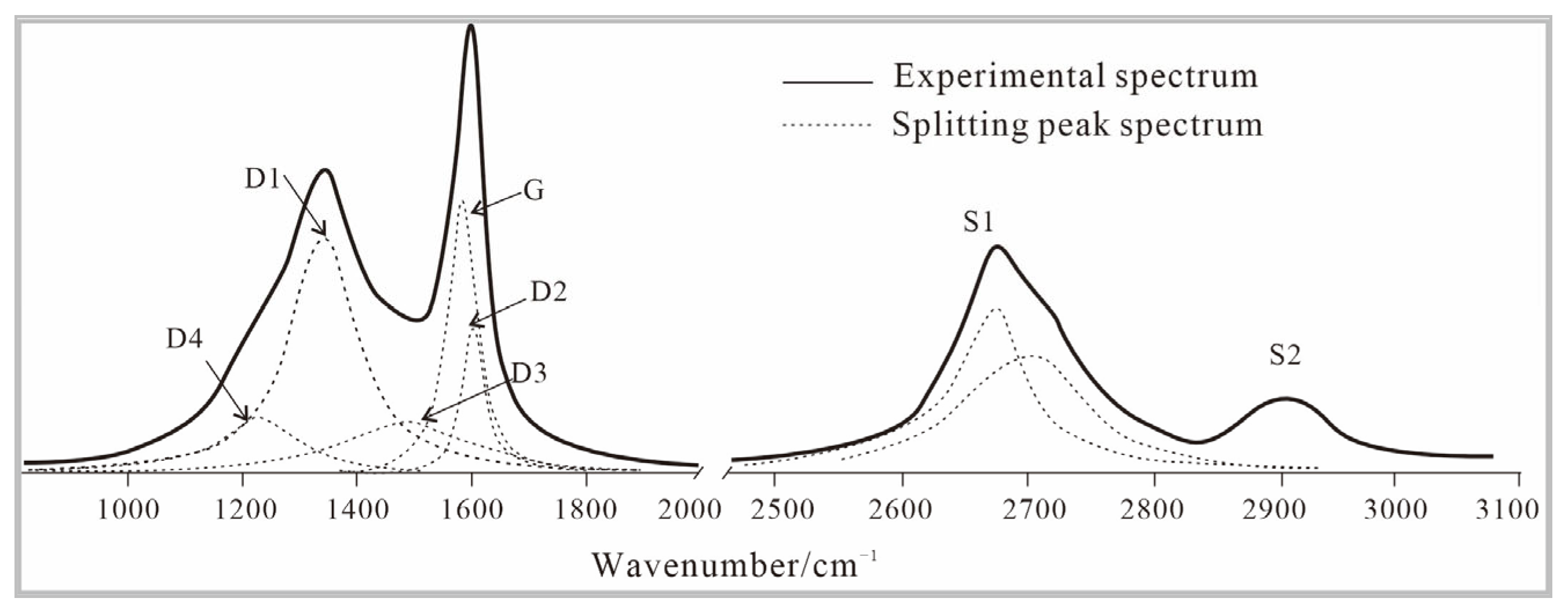
The obtained Raman spectra were analyzed using Origin 8.0 software, utilizing Lorentzian functions for fitting and processing. The Raman spectrum exhibited two bands: the first-order Raman (700 cm−1 to 2000 cm−1) and the second-order Raman (2000 cm−1 to 3000 cm−1). The first-order Raman spectrum showed four types of defect peaks, namely D1 to D4 peaks, and an ordered graphite peak G. D1 represents in-plane defects caused by the incorporation of impurities or imperfect structure, which are difficult to eliminate during graphitization. D2 represents interstitial defects in the graphite lattice [25,26]. D3 and D4 are out-of-plane defects in the carbon layers and belong to active sites, which are released and eliminated during the early stages of graphitization [27]. The second-order Raman spectrum initially showed only two peaks, S1 and S2, in the low evolution stage. As the degree of evolution increased, the S1 peak gradually split into two peaks, and the S2 peak disappeared (Figure 2).
Researchers often use the ratio R2 = AD1/(A(G+D1+D2)), where AD1 represents the area under the D1 peak, to characterize the degree of structural defects or the degree of order in carbon materials [28]. This parameter can effectively represent the development of graphite structure defects in carbon materials with a high degree of evolution and a single type of defect and fewer defects. However, if the sample has a lower degree of evolution, complex defect types, and a higher proportion of defects, this parameter may not adequately evaluate the development of the sample. Therefore, in addition to using the R2 parameter, this paper proposes the R3 parameter, which represents the ratio of the total area under all types of defect peaks in the first-order Raman spectrum to the total area under all peaks (R3 = A(D1+D2+D3+D4)/A(D1+D2+D3+D4+G)).
R2 is referred to as the “in-plane defect parameter” that characterizes the proportion of in-plane defects (D1) and has good evaluation significance for samples with a high degree of evolution, fewer defects, and a dominance of D1-type defects (highly evolved graphite samples), and it can be used for cross-comparison with other relevant studies. R3 is referred to as the “overall defect parameter” that represents the proportion of all types of defects and has significant physical meaning for samples with a lower degree of evolution and more defects.

2.4. Transmission Electron Microscopy

The experiments utilized the Tecnai G2 F30 field emission transmission electron microscope (TEM) with an acceleration voltage of 300 kV. The point resolution was 0.20 nm, the line resolution was 0.10 nm, and the information resolution was 0.14 nm. The magnification ranged from 3000× to 500,000×.
The specific procedure involved grinding the sample to 300 mesh and then dispersing it in ethanol using ultrasonic treatment. The dispersed sample was then dropped onto a copper mesh. Subsequently, the sample was searched for on the holes of the copper mesh, and particles that could represent the majority of the particle characteristics within the sample were selected for multiscale observation. High-resolution images and selected area diffraction (SAD) patterns were captured during the observation process.

3. Results

3.1. X-ray Diffraction

3.1.1. Precursors

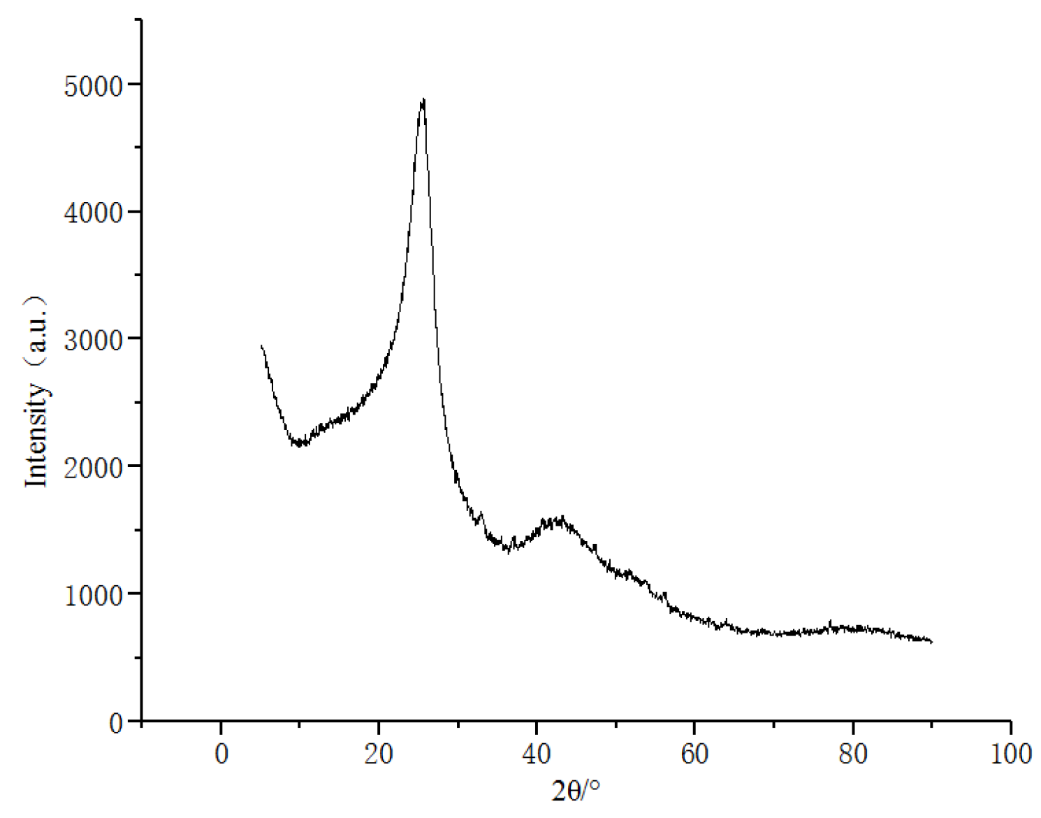
X-ray diffraction (XRD) has been widely utilized in the study of coal structure [29]. When the sample mainly consists of amorphous carbon, sharp silicon peaks can influence the shape of the carbon peaks. Therefore, silicon powder calibration is not applied to such samples. Instead, an estimation is made for the d002, La, and Lc parameters (Figure 3). The estimated values are as follows: d002 = 0.3494 nm, La = 2.822 nm, and Lc = 1.529 nm.

3.1.2. High-Temperature Thermal Simulation Experiments (HTT)

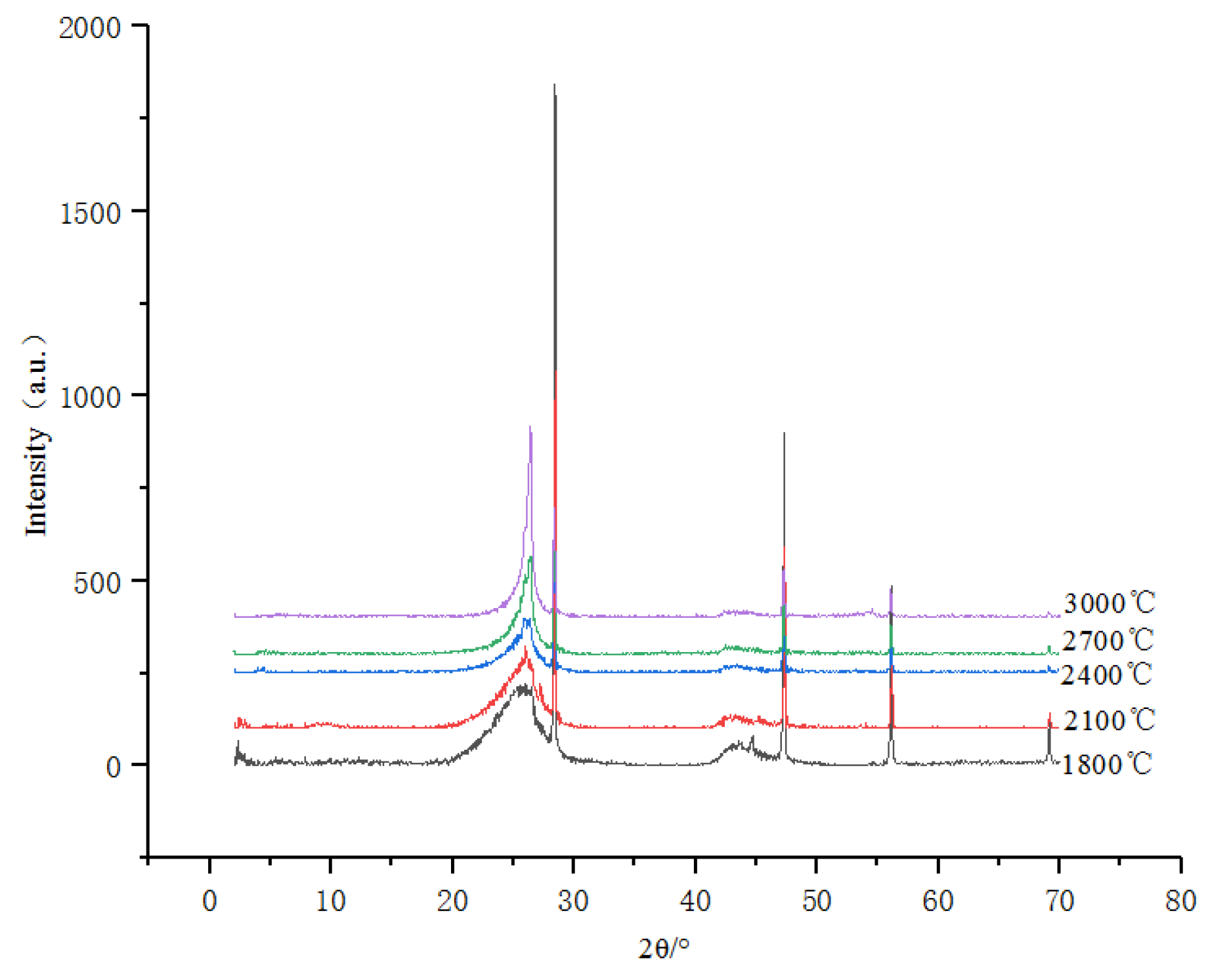
As the processing temperature increases, the carbon peak at 2θ = 26° approaches the position of the standard graphite peak at 2θ = 26.6° (Figure 4). The peak becomes sharper, and at different processing temperatures the peak shape exhibits an asymmetry, with a steeper slope on the right. The largest change in d002 occurs at the temperature intervals of initial state → 1800 °C and 2100 °C → 2400 °C. From 1800 °C to 2100 °C, d002 remains relatively stable with minimal changes (Table 2).

3.1.3. High-Temperature and High-Pressure Simulation Experiments (HTHP)

Under the condition of 600 °C, the peaks around 2θ = 26° exhibit a broad and flat shape (opposite to sharp peak shape). At 900 °C, the full width at half maximum (FWHM) of the peaks near 2θ = 26° significantly decreases. Under the condition of 1200 °C, the (002) peak becomes sharp and symmetrical, indicating the formation of perfect graphite crystals (Figure 5).
Using d002 as a measure of graphitization degree, the involvement of “force” significantly reduces the initiation temperature of sample graphitization. With the assistance of force, under the condition of 1200 °C, the graphitization degree of the inertinite exceeds that of the 3000 °C high-temperature simulated experiment (Table 3). Compared to the corresponding samples in the high-temperature simulated experiment, the symmetry of the peaks around 2θ = 26° is higher, indicating a more uniform evolution of the HTHP experimental samples.

3.2. Raman Spectroscopy

3.2.1. Precursors

The Raman spectrum of the inertinite-rich precursor (Figure 6) indicates the presence of various types of defects. The predominant defects are of D1 and D2 types, while the presence of D3 and D4 defects suggests the presence of reactive structures such as fatty structures or polyene structures [30]. The secondary Raman spectrum does not show any splitting of the S1 peak, indicating the absence of a three-dimensional structure. Peak fitting analysis yields the following values: R2 = 0.65 and R3 = 0.83.

3.2.2. High-Temperature Thermal Simulation (HTT)

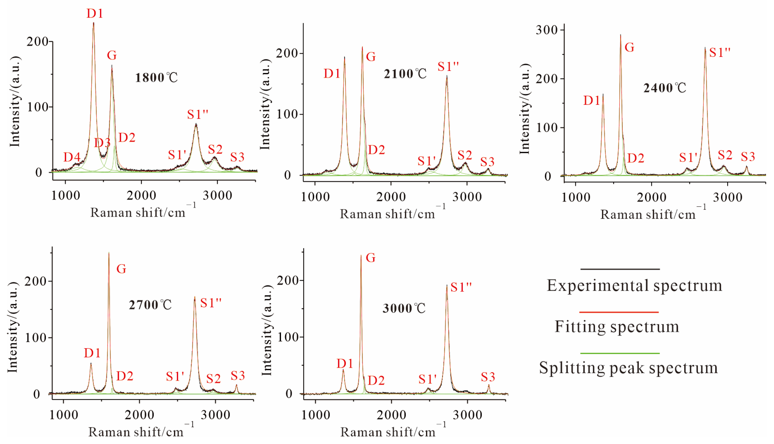
With increasing treatment temperature, the G peak representing the ordered graphite structure gradually intensifies and shifts towards 1580 cm−1, while the intensity of the D peaks representing the disordered structure weakens. Among the defect peaks, the D1 peak is predominantly present, and even in samples with high degrees of graphitization, the D2 peak does not completely disappear. However, other heteroatom-related defect peaks, D3 and D4, disappear completely under high-temperature treatment conditions (Figure 7). Beyond 1800 °C, the D3 defect peak is almost undeveloped (except for a few samples that exhibit weak D4 defect peaks), and beyond 2400 °C, the D4 peak is no longer present.
As the treatment temperature increases, in the second-order Raman spectrum, the S1 peak gradually splits into S1′ and S1″ peaks, while the S2 peak gradually disappears, indicating the progressive formation of a three-dimensional structure.
Quantitative evaluation and comparison of the defect development degree in the products of HTT simulation experiments are performed using the R2 and R3 parameters (Table 4). With increasing treatment temperature, the defect degree (R2 and R3) significantly decreases, but even at a treatment temperature of 3000 °C, it is difficult to reduce the defect degree below 0.1.

3.2.3. High-Temperature and High-Pressure Simulation Experiments (HTHP)

In the HTHP simulation experiment, compared to the high-temperature-treated samples, the HTHP samples exhibit higher defect density under similar d002 conditions (Figure 8; Table 5).
In the HTHP experiment, a clear secondary Raman peak representing the development of a three-dimensional ordered structure is observed only at temperatures above 900 °C. Under the temperature condition of 600 °C, regardless of the variation in pressure, the overall changes in the peak shape of the D and G peaks are minimal.
Similar to the HTT simulation experiments, the Raman characterization parameters of the HTHP samples were calculated (Table 5). We can observe that the HTHP samples exhibit some differences compared to the HTT samples. Under the 600 °C condition, the R2 value of the samples is lower than that of the 900 °C samples. This anomalous phenomenon is caused by the relatively higher proportion of D3 and D4 type defects in the 600 °C samples, resulting in a lower relative proportion of D1 defects, which leads to an abnormal value of the in-plane defect parameter R2.

3.3. Transmission Electron Microscopy

3.3.1. Precursors

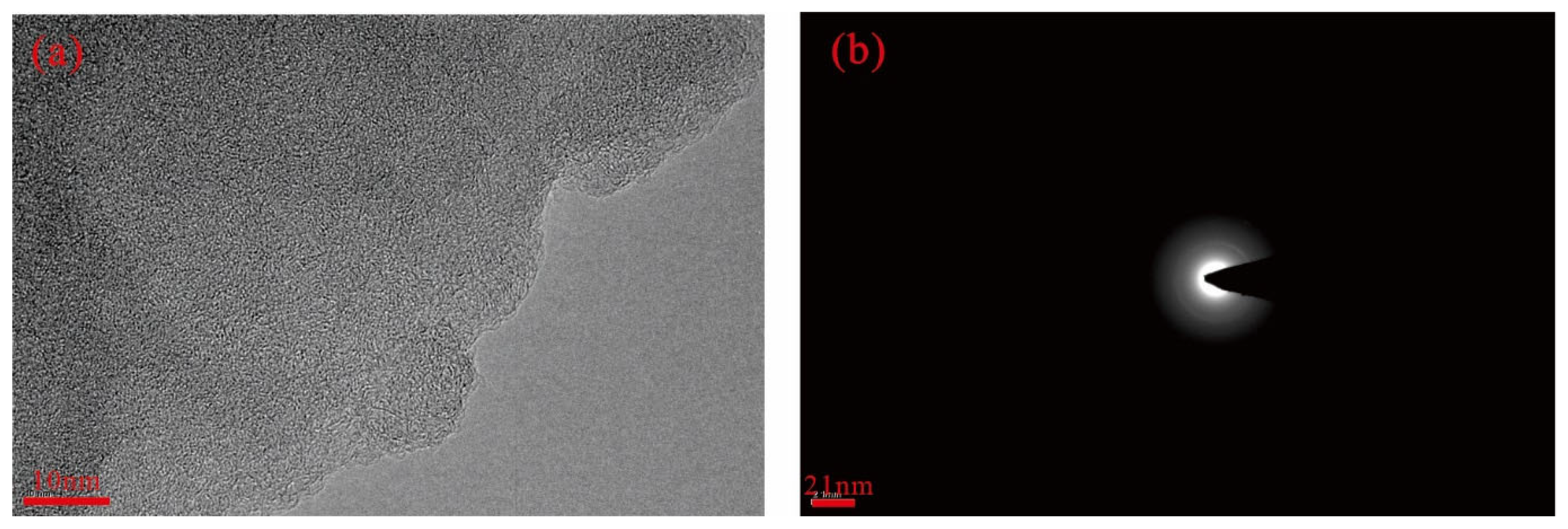
TEM reveals that the basic structural units (BSUs) in the large molecular structure of the precursor are small in size and arranged in a disordered manner (Figure 9a). The Selected Area Diffraction (SAD) pattern exhibits an amorphous diffraction ring (Figure 9b).

3.3.2. High-Temperature Thermal Treatment (HTT)

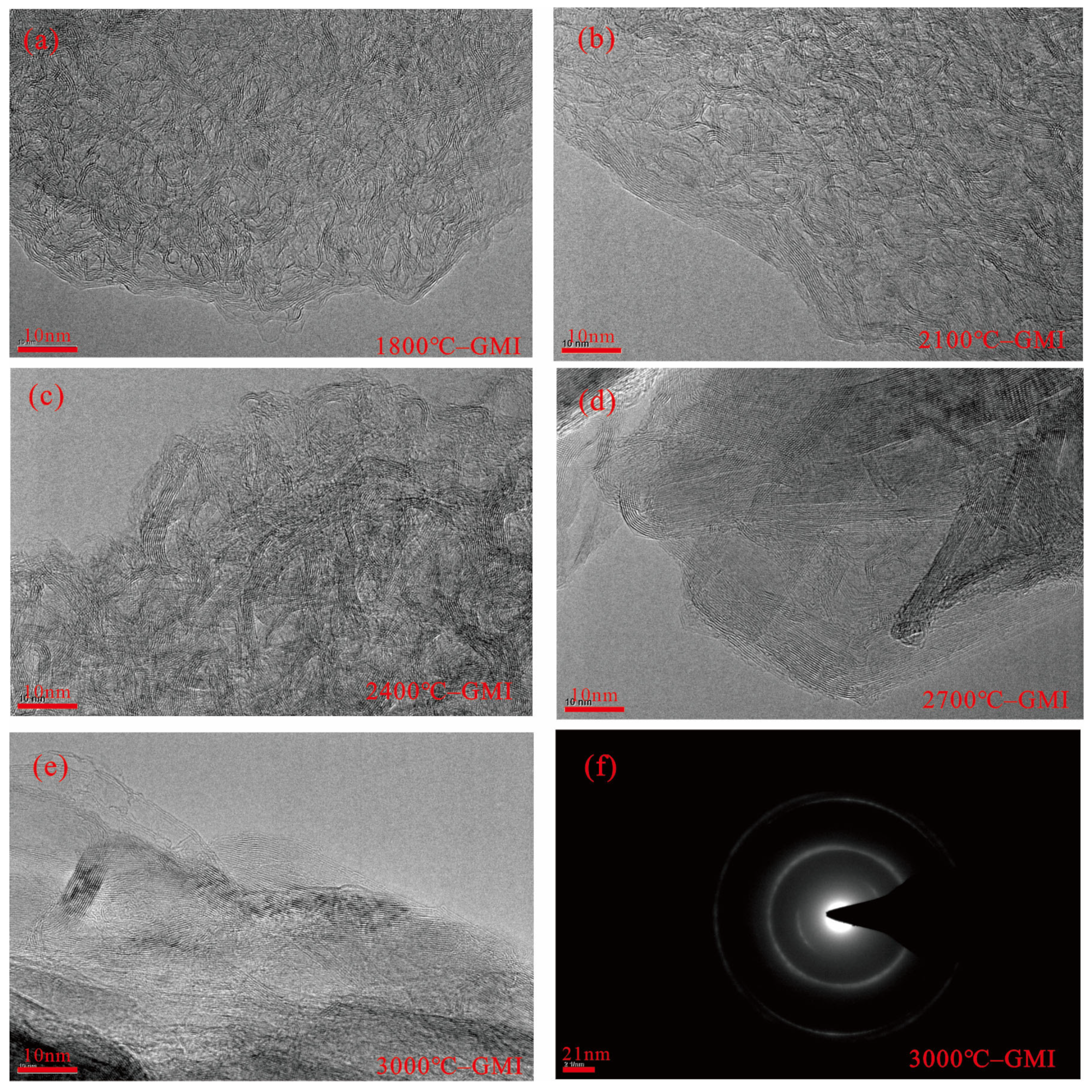
Transmission electron microscopy (TEM) observations of the products at different processing temperatures reveal a gradual increase in lattice expansion and stacking degree (Figure 10a–e). However, the morphology images show that the graphite lattice development direction varies, resulting in polycrystalline graphite (Figure 10c,d). The Selected Area Diffraction (SAD) pattern consists of concentric diffraction rings with different radii, indicating that the measured sample exhibits a polycrystalline structure (Figure 10f).

3.3.3. High-Temperature and High-Pressure Simulation Experiment (HTHP)

At 900 °C, under a pressure of 1.5 GPa/2 GPa, the formation of graphite structure begins, with carbon layers stacking to about five layers and an extended length of up to 10 nm (Figure 11a,b). Under the condition of 900 °C/2 GPa, an onion-ring concentric microtexture is formed, which is a transitional product of large-sized flat graphite structure (Figure 11b).
At 1200 °C, under the combination of 1.5 GPa/2 GPa, graphite flakes are formed (Figure 11c–e), but the graphite exhibits distinct “rough in-plane, flat interlayer” structural features (Figure 11e). At the same time, it can be observed that the stacking of carbon layers in the high-temperature high-pressure product is relatively low, generally concentrated within 10 layers, but with a significant extension and smooth stacking. The in-plane development is rough, indicating a high degree of defects. The SAD pattern shows a regular arrangement of diffraction spots, indicating that the product is mainly single crystal (Figure 11f).

4. Discussion

4.1. Threshold Conditions for Graphitization of Inertinite

The evolution of a graphite lattice involves two aspects: the construction of a three-dimensional lattice and the elimination of lattice defects. High-temperature thermal simulation experiments show that the inertinite exhibits a “inert” state between processing temperatures of 1800 °C and 2100 °C (where d002 remains above 0.3420 nm in a disordered state). Once the processing temperature exceeds 2100 °C, the inertinite undergoes a significant change. There exists a graphitization threshold (Critical Temperature) for the inertinite between 2100 °C and 2400 °C where only temperatures above this threshold can achieve rapid graphitization, and the d002 value decreases to around 0.3380 nm. From 2400 °C to 3000 °C, the rate of decrease in d002 slows down again, approaching the standard graphite lattice value of 0.3354 nm (Figure 12a).
As the processing temperature increases, the defects in the graphite lattice are uniformly eliminated, and the temperature plays an absolute control role in defect elimination. The high-temperature thermal vibration promotes the elimination of defects. At higher processing temperatures, due to the disappearance of D3 and D4 defects, the “in-plane defect parameter” R2 is almost identical to the “total defect parameter” R3 (Figure 12b).

4.2. Catalytic Effect of Structural Stress on Graphitization

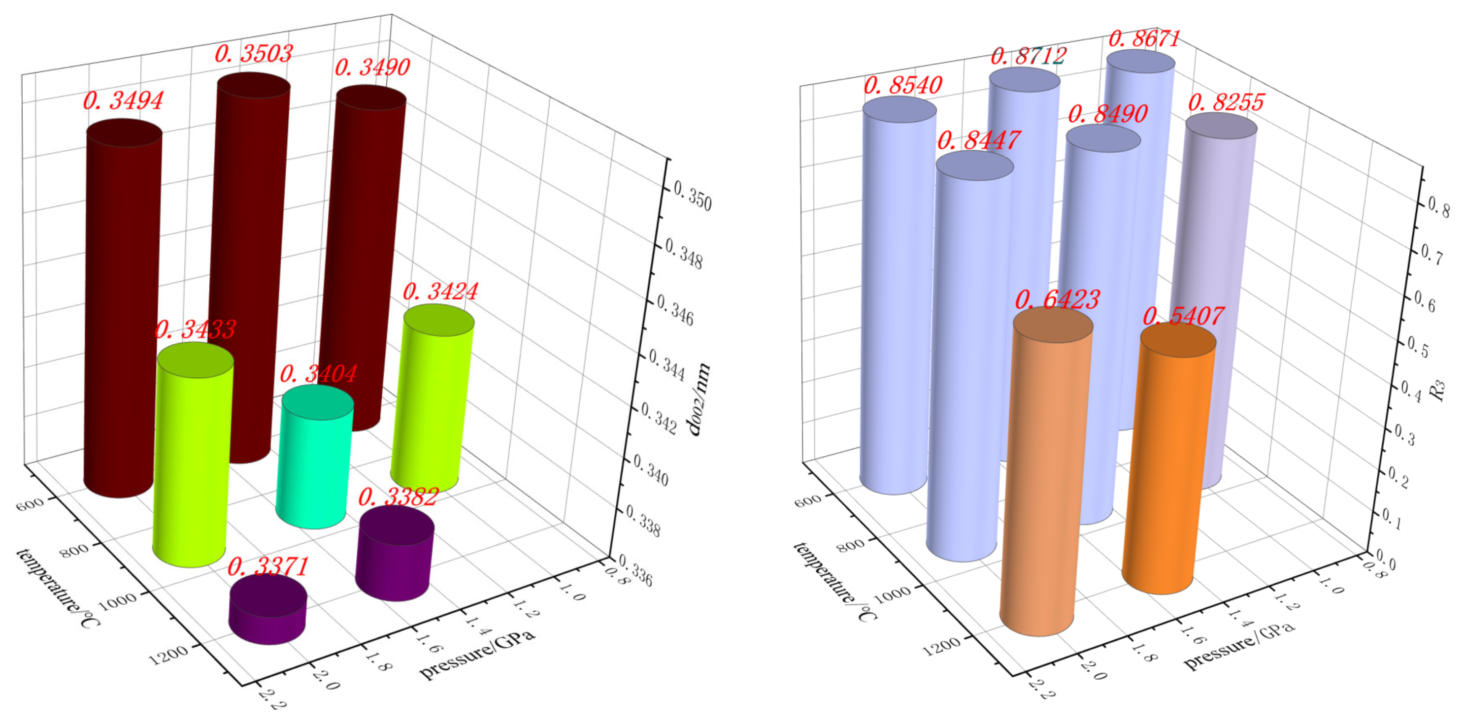
In HTHP simulation experiments, the inertinite showed no significant change in d002 under all pressure conditions at 600 °C. Only at 900 °C did the d002 of the inertinite decrease significantly. Among the different pressure conditions at 900 °C, the product obtained under 900 °C/1.5 GPa exhibited the smallest d002 value, falling below 0.3420 nm (the starting point of carbon material graphitization proposed by Oberlin et al., (1984)) [31]. This indicates that the synergistic combination of suitable pressures is required for the manifestation of the temperature effect, as excessively high or low pressure is unfavorable for structural development (Figure 13).
By comparing HTHP simulation experiments with HTT simulation experiments, the importance of force in the graphitization process is demonstrated. Compared to the pure high-temperature treatment at 3000 °C in the HTT simulation experiments, the sample obtained at 1200 °C/1.5 GPa has a smaller d002 value (Table 6).
The role of stress is mainly to promote the stacking of carbon layers in the three-dimensional direction and the growth in the two-dimensional direction, while its effect on the elimination of in-plane defects is relatively small. The graphite structure formed under high temperature and high pressure conditions (1.5 GPa, 1200 °C) exhibits a better three-dimensional lattice structure (d002, La, Lc) compared to the samples simulated under high temperature (3000 °C). However, its defect level is higher than that of the high-temperature simulation (3000 °C) samples (with higher D peak) but lower than that of the pure high-temperature-treated samples at 1800 °C (Table 6). This indicates that the involvement of stress can indeed reduce the defect level of the samples, but its effect is relatively weak. TEM observations also reveal that the products of HTHP consist of flat graphite layers with significant surface defects (Figure 11d).

4.3. The Mechanism of Stress in the Graphitization Process

In this experiment, hydrostatic pressure was applied, meaning that the sample experienced the same force in all directions. If the sample is highly symmetrical, then any point inside experiences isotropic hydrostatic pressure. However, it should be noted that coal has various types of well-developed pore structures, which inherently exhibit high asymmetry and non-uniformity [32]. In this HTHP experiment, the sample was formed by powder compaction, which also resulted in the formation of numerous pores of different sizes within the sample.
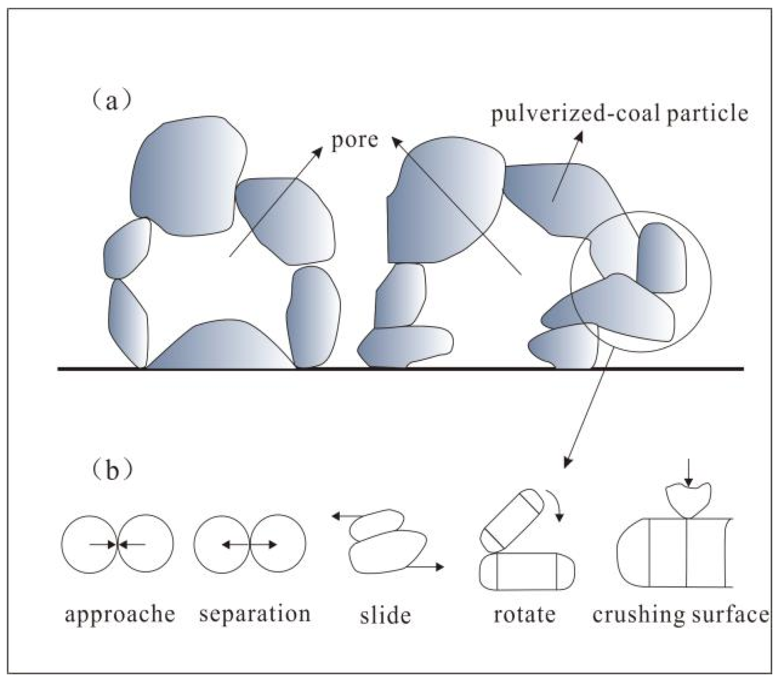
In the HTHP experiment, the introduction of external forces disrupts the arching effect and causes relative movement between particles, resulting in different stress states [33,34] (Figure 14). Although the sample as a whole is subjected to hydrostatic pressure, there still exist differential stresses within the internal structure, and any contact point in the sample may have shear effects [35,36]. The internal structure of the sample responds to external forces by migration or reconstruction in order to release and eliminate shear stress, and this effect of stress can even occur at the nanoscale level [37].
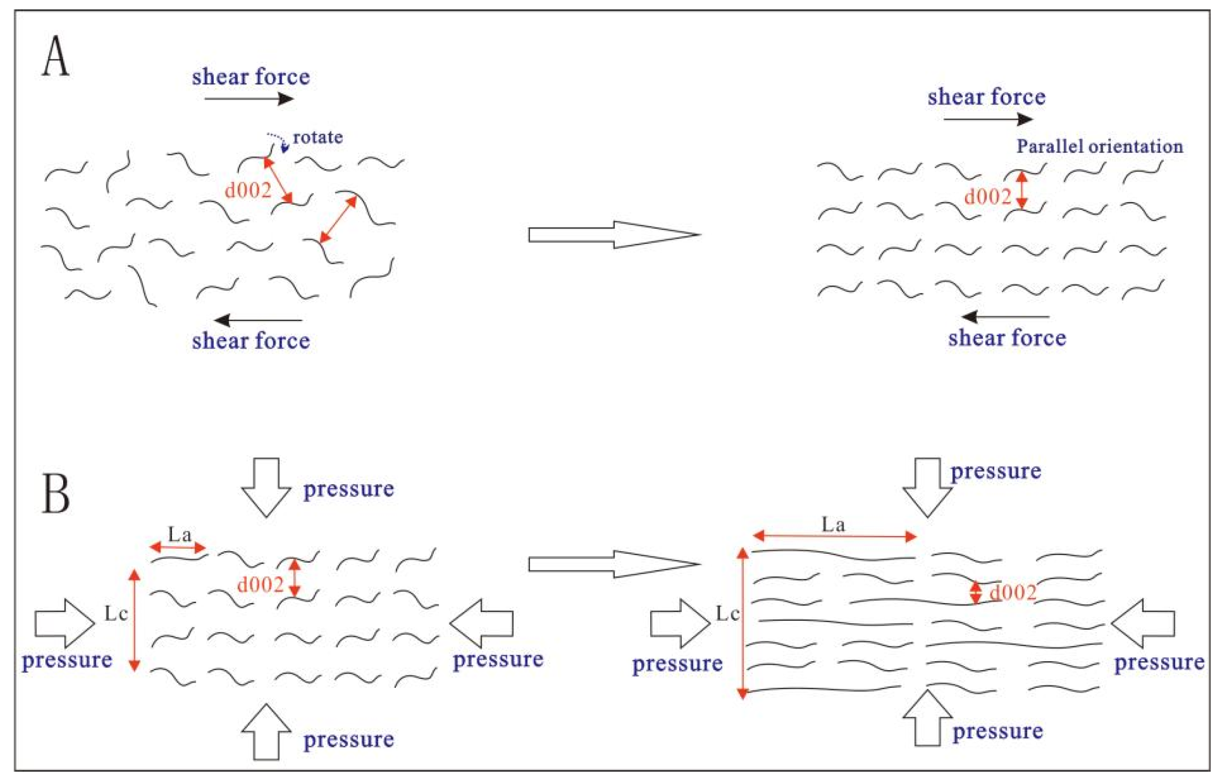
Static hydrostatic pressure and shear stress play different roles in the construction of a graphite structure. Shear stress promotes the rotation and orientation of aromatic layers. Static hydrostatic pressure has a positive effect on the contraction and reduction of interlayer spacing in carbon layers (Figure 15).
It is important to note that the overall effect of applying hydrostatic pressure to the sample is weaker than the effects of axial compression and shear stress. As the asymmetry of the applied force increases, the differences in the effects of these three forces become smaller. In the case of a perfectly symmetrical object, where the force directions at any point within the sample are isotropic with no differential stress, static hydrostatic pressure will not have any positive effect.

5. Conclusions

(1)
Through HTT and HTHP simulation experiments, it has been demonstrated that the inertinite in coal can undergo graphitization, but there exists a structural transformation threshold. In the HTT simulation experiments, the inertinite remains in an “inert” state (with d002 stagnant before reaching 0.3420 nm) within the temperature range of 1800 °C to 2100 °C. However, beyond 2100 °C, the inertinite undergoes transformation.
(2)
The HTHP experiments indicate that at a temperature of 600 °C, the variation in pressure does not lead to any significant structural changes. However, at 900 °C/1.5 GPa, the d002 value decreases to below 0.3420 nm. There exists an optimal pressure for the development of the graphite lattice.
(3)
Force has a significant promoting effect on the construction of the three-dimensional lattice, while its impact on the elimination of lattice defects is relatively minor. Compared to the high-temperature treatment at 3000 °C (atmospheric pressure), the sample obtained at 1200 °C/1.5 GPa exhibits a smaller d002 value but a higher degree of defects (as indicated by the higher D peaks), albeit lower than that of the pure high-temperature treatment at 1800 °C.
(4)
A potential mechanism by which force promotes graphitization is analyzed and summarized. It involves the internal structure of the sample responding to external forces through different modes (migration or reconstruction) to release and eliminate shear and pressure effects, thereby promoting the rotation and orientation of aromatic layers and reducing the interlayer spacing (d002).

Author Contributions

Conceptualization, Z.L.; methodology, Z.L.; software, Q.C.; formal analysis, Z.L.; investigation, Q.C.; resources, D.C. and Z.B.; data curation, G.C.; writing—original draft preparation, Z.L. and G.C.; writing—review and editing, Z.L.; supervision, D.C. and Z.B.; funding acquisition, D.C. All authors have read and agreed to the published version of the manuscript.

Funding

This research was funded by The National Natural Science Foundation of China (42072197, 41772156), and Special project of Science and Technology Innovation and Entrepreneurship Fund of China Coal Science and Industry Group Co., LTD (2019-ZD004).

Data Availability Statement

All relevant data are within the paper.

Acknowledgments

The National Natural Science Foundation of China (42072197, 41772156) financially support this research.

Conflicts of Interest

The authors declare no conflict of interest.

References

  1. Marqués, M.; Suárez-Ruiz, I.; Flores, D.; Guedes, A.; Rodrigues, S. Correlation between optical, chemical and micro-structural parameters of high-rank coals and graphite. Int. J. Coal Geol. 2009, 77, 377–382. [Google Scholar] [CrossRef]
  2. Cao, D.; Zhang, H.; Dong, Y.; Yang, C. Nanoscale Microscopic Features and Evolution Sequence of Coal-Based Graphite. J. Nanosci. Nanotechnol. 2017, 17, 6276–6283. [Google Scholar] [CrossRef]
  3. Rao, J.; Zhang, P.; He, S.; Li, Z.; Ma, H.; Shen, Z.; Miao, S. A review on the utilization of natural graphite and graphite-based materials. Sci. Sin. Technol. 2017, 47, 13–31. [Google Scholar] [CrossRef]
  4. Cao, D.Y.; Zhang, H.; Dong, Y.J.; Wu, G.; Ning, S.; Mo, J.; Li, X. Research status and key directions of geological study on coal-based graphite. Earth Sci. Front. 2017, 24, 317–327. (In Chinese) [Google Scholar]
  5. Franklin, R.E. The structure of graphitic carbon. Acta Crystallogr. 1951, 4, 253–261. [Google Scholar] [CrossRef]
  6. Bonijoly, M.; Oberlin, M.; Oberlin, A. A possible mechanism for natural graphite formation. Int. J. Coal Geol. 1982, 1, 283–312. [Google Scholar] [CrossRef]
  7. Wang, L.; Dong, Y.J.; Zhang, H.; Cao, D.Y. Factors influencing coal graphitization and their experimental verification. J. Mineral. Sci. 2018, 3, 9–19. (In Chinese) [Google Scholar]
  8. Nyathi, M.S.; Clifford, C.B.; Schobert, H.H. Characterization of graphitic materials prepared from different rank Pennsylvania anthracites. Fuel 2013, 114, 244–250. [Google Scholar] [CrossRef]
  9. Beyssac, O.; Rouzaud, J.N.; Goffe, B.; Brunet, F.; Chopin, C. Graphitization in a high-pressure, low-temperature metamorphic gradient: A Raman microspectroscopy and HRTEM study. Contrib. Mineral. Petrol. 2002, 143, 19–31. [Google Scholar] [CrossRef]
  10. Diessel, C.F.K.; Brothers, R.N.; Black, P.M. Coalification and graphitization in high-pressure schists in New Caledonia. Contrib. Mineral. Petrol. 1978, 68, 63–78. [Google Scholar] [CrossRef]
  11. Rodrigues, S.; Suárez-Ruiz, I.; Marques, M.; Flores, D. Catalytic role of mineral matter in structural transformation of anthracites during high temperature treatment. Int. J. Coal Geol. 2012, 93, 49–55. [Google Scholar] [CrossRef]
  12. Li, J.; Qin, Y.; Chen, Y.; Luo, Q.; Deng, R.; Guo, S.; Chen, Q. Differential graphitization of organic matter in coal: Some new understandings from reflectance evolution of meta-anthracite macerals. Int. J. Coal Geol. 2021, 240, 103747. [Google Scholar] [CrossRef]
  13. Dai, S.F.; Bechtel, A.; Eble, C.F.; Flores, R.M.; French, D.; Graham, I.T.; Madison, M.; Hood, M.M.; Hower, J.C.; Korasidis, V.A.; et al. Recognition of peat depositional environments in coal: A review. Int. J. Coal Geol. 2020, 219, 103383. [Google Scholar] [CrossRef]
  14. Niekerk, D.V.; Jonathan, P.; Mathews, J.P. Molecular representations of Permian-aged vitrinite-rich and inertinite-rich South African coals. Fuel 2010, 89, 73–82. [Google Scholar] [CrossRef]
  15. Li, J.; Feng, J.; Wen-Ying, L.I. Thermochemical Reaction Representation of Shenfu Dongshen Inertinite and Vitrinite. Acta Phys. Chim. Sin. 2009, 25, 1311–1319. [Google Scholar]
  16. Wilks, K.R.; Mastalerz, M.; Ross, J.V.; Bustin, R.M. The effect of experimental deformation on the graphitization of Pennsylvania anthracite. Int. J. Coal Geol. 1993, 24, 347–369. [Google Scholar] [CrossRef]
  17. Bustin, R.M.; Ross, J.V.; Rouzaud, J.N. Mechanisms of graphite formation from kerogen: Experimental evidence. Int. J. Coal Geol. 1995, 28, 1–36. [Google Scholar] [CrossRef]
  18. Pappano, P.J. A Mechanism of Pennsylvania Anthracite Graphitization Involving Carbide Formation and Decomposition; The Pennsylvania State University: State College, PA, USA, 2003. [Google Scholar]
  19. Atria, J.V.; Rusinko, F.; Schobert, H.H. Structural Ordering of Pennsylvania Anthracites on Heat Treatment to 2000–2900 °C. Energy Fuels 2002, 16, 1343–1347. [Google Scholar] [CrossRef]
  20. Pappano, P.J.; Schobert, H.H. Effect of Natural Mineral Inclusions on the Graphitizability of a Pennsylvania Anthracite. Energy Fuels 2009, 23, 422–428. [Google Scholar] [CrossRef]
  21. He, Q.; Tang, J.J.; Wang, F.; Liu, X. An assembly of six-face top-pressure machines suitable for extreme high-temperature conditions. Chin. J. High Press. Phys. 2014, 28, 145–151. (In Chinese) [Google Scholar]
  22. Jiang, B.; Qin, Y. Experimental study on coal deformation under high temperature and high pressure. J. China Coal Soc. 1997, 22, 82–86. (In Chinese) [Google Scholar]
  23. Jiang, B.; Qin, Y.; Jin, F.L. Deformation characteristics of coal macerals under high temperature and high pressure. Geol. Sci. 1998, 21, 17–24. (In Chinese) [Google Scholar]
  24. Zhao, F.H. Composition and Structure of Coal—Transmission Electron Microscopy (TEM) and X-ray Diffraction (XRD) Study on Coal Structure; China University of Mining and Technology: Beijing, China, 1994. (In Chinese) [Google Scholar]
  25. Beny-Bassez, C.; Rouzaud, J.N. Characterization of carbonaceous materials by correlated electron and optical microscopy and Raman microspectroscopy. Scanning Electron Microsc. 1985, 1985, 119–132. [Google Scholar]
  26. Beyssac, O.; Goffé, B.; Chopin, C.; Rouzaud, J.N. Raman spectra of carbonaceous material in metasediments: A new geothermometer. J. Metamorph. Geol. 2002, 20, 859–871. [Google Scholar] [CrossRef]
  27. Beyssac, O.; Goffé, B.; Petitet, J.P.; Froigneux, E.; Moreau, M.; Rouzaud, J.N. On the characterization of disordered and heterogeneous carbonaceous materials by Raman spectroscopy. Spectrochim. Acta A Mol. Biomol. Spectrosc. 2003, 59, 2267–2276. [Google Scholar] [CrossRef]
  28. Rantitsch, G.; Lämmerer, W.; Fisslthaler, E.; Mitsche, S.; Kaltenböck, H. On the discrimination of semi-graphite and graphite by Raman spectroscopy. Int. J. Coal Geol. 2016, 159, 48–56. [Google Scholar] [CrossRef]
  29. Harris, L. Quantitative X-ray diffraction analysis and its application to various coals. Carbon 2001, 39, 1821–1833. [Google Scholar]
  30. Su, X.B.; Si, Q.; Song, J.X. Raman spectroscopic characteristics of coal. J. China Coal Soc. 2016, 41, 1197–1202. (In Chinese) [Google Scholar]
  31. Oberlin, A. Carbonization and graphitization. Carbon 1984, 22, 521–541. [Google Scholar] [CrossRef]
  32. Zhou, H. Study on Microcrystal Structure and Pore Structure Characteristics of Organic Microscopic Components in Coal; Henan Polytechnic University: Zhengzhou, China, 2018. (In Chinese) [Google Scholar]
  33. Chen, Y.X.; Du, J.G.; Liu, H. Distribution of boundary stress of mineral particles under high temperature and high static pressure. J. Cent. South Univ. 2010, 41, 286–292. (In Chinese) [Google Scholar]
  34. Ciz, R.; Siggins, A.F.; Gurevich, B.; Dvorkin, J. Influence of microheterogeneity on effective stress law for elastic properties of rocks. Geophysics 2007, 73, 7–14. [Google Scholar] [CrossRef] [Green Version]
  35. Liu, L.M.; Wu, Y.Z. Chemical behavior of crystalline minerals under shear stress and its geological significance. Geol. Explor. 1996, 31, 26–31. (In Chinese) [Google Scholar]
  36. Feng, Z.C.; Zhao, D.; Wang, J.F. Stress distribution characteristics of rocks under static water pressure. In Proceedings of the 11th National Conference on Rock Mechanics and Engineering, Wuhan, China, 19–21 November 2011; Chinese Society for Rock Mechanics and Engineering: Beijing, China, 2011. (In Chinese). [Google Scholar]
  37. Sun, J. In-Situ Transmission Electron Microscopy Study on Structural Evolution of Materials under External Fields; Southeast University: Nanjing, China, 2016. (In Chinese) [Google Scholar]
  38. Wang, M.B. Study on Powder Compaction; Jilin University: Changchun, China, 2007. (In Chinese) [Google Scholar]
Figure 1. High-temperature and high-pressure simulation experimental sample.
Minerals 13 00888 g001
Figure 2. Illustration of peak assignment in Raman spectra of carbon materials.
Minerals 13 00888 g002
Figure 3. XRD pattern of simulated experimental precursor (inertinite-rich sample).
Minerals 13 00888 g003
Figure 4. XRD pattern for the products of HTT simulation experiments.
Minerals 13 00888 g004
Figure 5. XRD pattern for the products of HTHP simulation experiment.
Minerals 13 00888 g005
Figure 6. Raman spectrum of the simulated precursor (inertinite-rich sample).
Minerals 13 00888 g006
Figure 7. Raman spectrum for the products of HTT simulation experiments.
Minerals 13 00888 g007
Figure 8. Raman spectrum for the products of HTHP simulation experiments.
Minerals 13 00888 g008
Figure 9. TEM characteristics of the simulated precursor. (a) Aromatic fringe morphology of samples with high magnification, (b) The selected area diffraction (SAD) pattern.
Minerals 13 00888 g009
Figure 10. TEM characteristics for the products of HTT simulation experiment. (ae) Aromatic fringe morphology of sample GMI treated at different temperatures, (f) The selected area diffraction (SAD) pattern of sample GMI treated at 3000 °C.
Minerals 13 00888 g010
Figure 11. TEM features for the products of HTHP simulation experiments. (a,b) Aromatic fringe morphology of 900 °C–1.5 Gpa–GMI and 900 °C–2 Gpa–GMI with high magnification, (c) Aromatic fringe morphology of 1200 °C–1.5 Gpa–GMI with low magnification, (d) Aromatic fringe morphology of 1200 °C–1.5 Gpa–GMI with high magnification, (e) Aromatic fringe morphology of 1200 °C–2 Gpa–GMI with high magnification, (f) The selected area diffraction (SAD) pattern of 1200 °C–2 Gpa–GMI.
Minerals 13 00888 g011
Figure 12. Evolution of structural parameters during the graphitization of inertinite. (a) The variation characteristics of d002 value with temperature, (b) The variation characteristics of R2 and R3 value with temperature.
Minerals 13 00888 g012
Figure 13. Evolution of structural parameters during the graphitization process of the inertinite.
Minerals 13 00888 g013
Figure 14. Depicts the displacement of powder particles under compressed conditions in the sample [38]. (a) illustrates the formation of arching effect among powder particles, (b) represents the displacement modes of powder particles.
Minerals 13 00888 g014
Figure 15. Illustrates the influence of force on the orientation arrangement of aromatic layers and the reduction of interlayer spacing. (A) Shear force promotes the rotation and orientation of aromatic layers, (B) Pressure has a positive effect on the contraction and reduction of interlayer spacing in carbon layers.
Minerals 13 00888 g015
Table 1. Basic information of the inertinite-rich sample.
SampleMaceralIndustrial AnalysisElemental Analysis
VitriniteInertiniteLiptiniteMadAdVdafFCdStOdafCdafHdafNdaf
GMI8.4%91.6%0.0%0.5% 7.3% 16.0% 81.2% 0.5% 3.2% 91.9% 3.5% 0.8%
M, moisture; A, ash yield; V, volatile matter; FC, fixed carbon; St, total sulfur; C, carbon; H, hydrogen; N, nitrogen; ad, air dry basis; d, dry basis; daf, dry and ash-free basis.
Table 2. XRD lattice parameter calculations for the products of HTT simulation experiments.
Processing Temperature002Lc/nmLa/nmd002/nm
1800 °C25.93 3.18 10.76 0.3433
2100 °C25.92 3.43 12.06 0.3434
2400 °C26.21 7.57 17.88 0.3398
2700 °C26.25 9.12 17.98 0.3393
3000 °C26.29 17.99 19.84 0.3387
Table 3. XRD lattice parameter calculations for the products of HTHP simulation experiment.
Processing Temperature/°CProcessing Pressure/Gpa002Lc/nmLa/nmd002/nm
6001.0 25.499 1.62 3.95 0.3490
1.5 25.405 1.88 1.60 0.3503
2.0 25.483 1.43 2.70 0.3494
9001.0 26.000 2.72 9.74 0.3424
1.5 26.1573.11 10.57 0.3404
2.0 25.932 2.30 6.23 0.3433
12001.5 26.330 17.68 60.79 0.3382
2.0 26.421 20.73 42.33 0.3371
Table 4. Raman parameter values for the products of HTT simulation experiments.
Processing Temperature/°C18002100240027003000
R20.592 0.509 0.409 0.277 0.189
R30.658 0.587 0.473 0.291 0.205
Table 5. Raman parameter values for the products of HTHP simulation experiments.
Processing Temperature/°C6009001200
Processing pressure/Gpa1.0 1.5 2.0 1.0 1.5 2.0 1.5 2.0
R20.712 0.692 0.689 0.745 0.763 0.760 0.472 0.527
R30.867 0.871 0.854 0.826 0.849 0.845 0.541 0.642
Table 6. Comparison of structural parameters between HTT and HTHP samples.
Experimental ConditionsSample IDXRD ParametersRaman
Temperature/°CRessure/Gpad002/nmLc/nmLa/nmR1R2R3
1800Atmospheric1800 °C–GMI0.34333.1810.761.520.5890.663
30003000 °C–GMI0.338717.9919.840.130.190.21
12001.51200 °C–1.5 GPa–GMI–70.338217.6860.790.60.470.54
Disclaimer/Publisher’s Note: The statements, opinions and data contained in all publications are solely those of the individual author(s) and contributor(s) and not of MDPI and/or the editor(s). MDPI and/or the editor(s) disclaim responsibility for any injury to people or property resulting from any ideas, methods, instructions or products referred to in the content.