Abstract
The shear mechanical properties of rock joints are crucial in assessing the stability and safety of rock structures, including slopes, rock dams, and tunnels. The yield stress serves as a pivotal point that distinguishes the linear and non-linear mechanical characteristics of rock joints. Due to its significance in risk monitoring and safety evaluation, this paper first provides an overview of the commonly employed methods for identifying the yield stress. Then, a novel displacement reduction method based on the displacement reduction coefficient is proposed and systemically examined. The comparison between the proposed method and existing methods based on shear experimental data suggests that the former is more adept at accurately determining the yield stress without subjective interference. Finally, this innovative method is employed to estimate the effects of external environmental factors on the yield stress of rock joints.
1. Introduction
Fractured rock masses are often characterized by extensive and intricate rock joints, which exert a significant influence on their mechanical behavior [1,2,3,4,5,6]. Multitudinous geotechnical engineering applications, including, but not limited to, rock foundations, mining operations, bridge piers, and tunnelling projects, have demonstrated that the shear slip along these joints will lead to serious structural instability [7,8,9,10,11]. Numerous extensively- recorded geological calamities, such as landslides, fault-slip rock bursts, and tunnel collapses, are induced by the shear failure of rock joints [12,13,14]. Therefore, extensive and intensive studies on the shear strength characteristics of rock joints perform crucial theoretical and practical significance for ensuring the engineering safety and preventing geological disasters [15,16,17,18,19,20].
Numerous scholars have studied the shear deformation process of rock joints through various approaches and obtained abundant results [21,22,23,24,25,26,27,28,29,30,31]. Currently, there are three main categories of research methods for analyzing the shear mechanical properties of rock joints: physical model experiments (laboratory and field tests), numerical simulations, and theoretical analyses [32,33,34,35,36,37,38,39,40,41,42]. The non-uniform fluctuation of joint surface, uneven contact between two walls, elastic deformation of rough bodies, and progressive deterioration frequently result in the shear mechanical behavior of rock joints exhibiting alternatingly linear and nonlinear characteristics [43,44]. Yield stress, peak strength, and residual strength are the key stress thresholds to classify these characteristics. In terms of peak strength, dozens of models have been introduced successively since Patton incorporated the shear dilatancy effect into the Mohr–Coulomb criterion to establish the bilinear strength model [45,46,47]. The joint roughness coefficient—joint compressive strength (JRC—JCS) model, proposed by Barton and Choubey [48], has gained widespread acceptance among researchers and engineers in the field of rock engineering. Furthermore, it has been explicitly adopted by the International Society for Rock Mechanics (ISRM) Commission [49]. The residual strength, also referred to as the ultimate strength, is an ideal concept that defines the shear stress at an adequate shear displacement. However, shear displacement is finite in laboratory tests, making it difficult to obtain the true residual strength as defined. Therefore, the ISRM commission suggests that once the shear displacement reaches 10% of the joint length, the corresponding shear stress can be regarded as the residual strength. Nevertheless, concerning the yield stress, despite its widely accepted definition, its estimation method is still in its infancy stage since existing prediction methods cannot precisely identify the yield stress. In fact, the safe and optimal design of rock structures (such as slopes and drifts) relies not only on peak strength but also on yield stress [50]. As stress reaches the yield level, interior damage gradually accumulates and considerable plastic deformation occurs along rock joints, resulting in notable non-linear mechanical characteristics, such as the nonlinear shear constitutive curve and smaller-asperity breaking on joint surfaces [51]. A comprehensive examination of the shear stress-shear displacement behavior of rock joints in the past half-century has revealed that relying solely on peak strength is inadequate for assessing the strength properties of such joints [52,53,54,55,56,57]. Instead, greater emphasis should be placed on determining the yield stress, as this can serve as an effective early warning indicator for potential engineering hazards. Therefore, it is imperative to develop a reliable prediction method for estimating yield stress [58].
Notwithstanding the extant research endeavors, the yield stress has not been comprehensively studied. If a correlation between stress levels and yield stress can be identified in either laboratory or field settings, it would enable precise assessment and evaluation of joint stability and damage degree of rock masses. This study aims to propose a novel method to accurately identify the shear yield stress. The paper is structured as follows: Section 2 provides an overview of existing methods for determining yield stress, and critically evaluates their strengths and limitations. In Section 3, a novel method is proposed in a simple and objective manner by introducing a displacement reduction coefficient to process shear stress-shear displacement data, eliminating the dependence on elastic parameters. To validate the efficacy of the proposed method, the results of the new method are compared with those of existing methods. Section 4 investigates the effect of external environmental factors on the determined yield stress. Finally, Section 5 summarizes the findings and outlines future research directions.
2. Literature Review
In direct shear tests, a certain normal stress is applied to the specimen prior to the application of shear stress parallel to the joint plane. Figure 1 illustrates a typical shear stress-shear displacement curve, which comprises two distinct stages: pre-peak and post-peak (stage III). The pre-peak stage can be further divided into two sub-stages: sub-stage I, characterized by linear elasticity, and sub-stage II, marked by yield, with the demarcation point at the yield point [59]. During the stage of linear elasticity, the shear stress exhibits a linear increase in proportion to the shear displacement, and the shear stiffness can be determined by calculating the slope of this line. The asperities between the joint surface perform prominent elasticity during this stage. Subsequently, the shear constitutive curve enters the yield stage, wherein the plastic shear displacement starts to occur, the asperities gradually wear and break, the shear stiffness is noticeably reduced, and the hanging side and heading side slip along the joint. Upon reaching the maximum peak shear stress, the contact plane experiences significant collapse, which in turn results in greater slipping along the joint. The roughness and undulation of the rock joints give rise to normal displacement, ultimately leading to the occurrence of dilation. Once the shear stress surpasses the bearing capacity of the asperities, the cumulative damage will cause a marked drop in shear stress, as displayed in Figure 1. Herein, the present study is centered on the identification of the yield point, which performs a crucial role in determining the shear mechanical behavior variation of rock joints. Over the past few decades, numerous investigations have been conducted to ascertain the yield point of the shear constitutive curve, which can be categorized as follows:
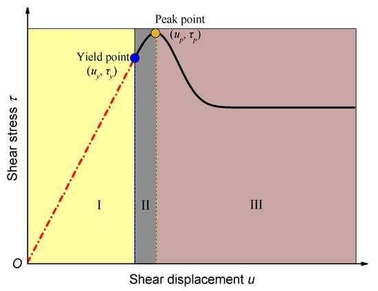
Figure 1.
Schematic diagram of the shear stress–shear displacement curve (uy and up are yield displacement and peak shear displacement, respectively; τy and τp are yield stress and peak shear stress, respectively).
- (1)
- Empirical methods
According to extensive direct shear experimental results conducted on rock joints by Goodman [60], it is typically observed that the yield point occurs within the range of 70% to 90% of the peak shear stress. Using this method, Xiao et al. [61] took a yield point equivalent to 70% of the peak shear stress to analytically derive a shear constitutive model. Similarly, Sun et al. [62] reported that the ratio between yield shear stress and peak shear stress is approximately 0.85. From the perspective of shear displacement, one-third of the peak shear displacement is regarded as the yield displacement by many researchers [52,53,63,64]. Although empirical methods may be convenient for engineering projects, they are highly subjective and do not account for important factors, such as lithology and pre-existing defects.
- (2)
- Shear stiffness method
The pre-peak stage of shear stress–shear displacement curves of rock joints are usually fitted using a hyperbolic function [65]. The following equation was adopted by Kulhawy [66] to replicate the pre-peak curve:
where ui is the shear displacement at a certain shear stress, m represents the reciprocal of the initial shear stiffness (Kst), and n is the reciprocal of the horizontal asymptote to the hyperbolic curve. By using Equation (1) to fit the experimental data, it is possible to readily derive the initial shear stiffness. Subsequently, a line originating from the origin O, with a slope of Kst, intersects with the shear stress-shear displacement curve at point F, which represents the yield point [67], as shown in Figure 2. This method is on the basis of shear test results. However, it is worth noting that determining the initial shear stiffness may be imprecise in situations where the shear stress–shear displacement curve does not exhibit a hyperbolic shape.
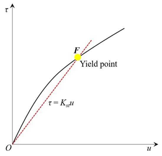
Figure 2.
Schematic diagram of the shear stiffness method.
- (3)
- Inflection point method
The linear fitting method was used by Xie et al. [68] to fit the experimental data in the pre-peak stage, and the resultant slope is the initial shear stiffness (Kst), as shown in Figure 3a. The shear stress difference (△τ) can then be obtained, and its relation versus shear displacement is illustrated in Figure 3b. The inflection point clearly corresponds to the yield point. Nonetheless, accurately pinpointing the inflection point remains a challenging task, as it is susceptible to subjective errors.
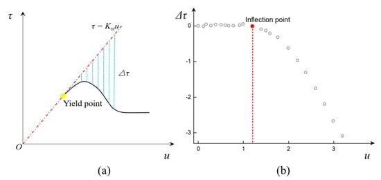
Figure 3.
Schematic diagram of the inflection point method, (a) τ-u curve (b) Δτ-u curve.
3. A New Displacement Reduction Method
Up to now, neither the ISRM nor the American Society for Testing and Materials have put forth any prescribed methods for accurately discerning the yield point [69]. Given the limitations of experience and subjective judgment, more academic approaches that enable a rapid and precise identification of the shear yield point are imperative to be established. To enhance the precision of determination and streamline the mathematical representation, a new method (i.e., displacement reduction method) is proposed herein to identify the yield stress of the shear constitutive curve. Additionally, the superiority of this method is validated by comparing it with existing methods.
3.1. Modeling Process
The displacement reduction method is used to determine the yield point by comparing the normalized shear displacement response (ui/up). The specific steps are as follows:
(1) A direct shear test is first carried out on rock joints to obtain the shear stress−shear displacement curve. Then, a new variable w is defined, which represents the displacement reduction coefficient:
where ui is the displacement data in the pre-peak stage of the shear stress–shear displacement curve, and up is the peak shear displacement. It is evident that w is a scalar quantity.
wi = 1 − ui/up
(2) The relationship between shear stress τ and displacement reduction coefficient w can be acquired, as shown in Figure 4. By applying Equation (2), points A (0, τp) and B (1, 0) can be identified, which correspond to the origin (0,0) and the peak point (up, τp) on the shear–stress displacement curve, respectively. It is obvious that points A (0, τp) and B (1, 0) always lie on the shear stress-w curve. Connecting these two points results in a reference line denoted as AB in Figure 4.
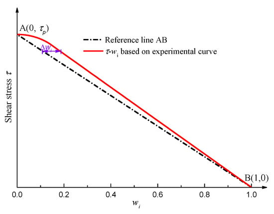
Figure 4.
Schematic diagrams of theoretical and experimental shear stress-w curves.
(3) Consequently, the difference Δw between the experimental shear–stress displacement curve and the reference line AB can be calculated, as plotted in Figure 5. During the linearly elastic stage (stage I), Δw increases proportionally with the increase in shear stress τ. In contrast, during the yield stage (stage II), the shear displacement exhibits non-linear characteristics. Hence, the yield point is the cut-off point between the linearly elastic stage (stage I) and the yield stage (stage II), where Δw reaches the maximum value. Consequently, this method enables easy identification of the yield point while ensuring accuracy and objectivity and eliminating human interference. This method provides a scientific and efficient means of determining the shear yield stress of rock joints.

Figure 5.
Δw-τ curve under direct shear tests.
3.2. Verification and Applications
The experimental data were collected through direct shear tests conducted on cement mortar specimens containing a saw-tooth triangular joint, as displayed in Figure 6. The specimens were composed of a mixture of water, high-strength cement, and fine quartz sand with a mass ratio of 1:2:4 [70]. The dimensional size and the undulating angle of the specimen were 100 × 100 × 100 mm3 and 45°, respectively. The uniaxial compressive strength, indirect tensile strength, Young’s modulus, Poisson′s ratio, cohesion, and internal friction angle of the cement mortar material are 18.97 MPa, 1.637 MPa, 2.202 GPa, 0.2, 1.84 MPa, and 58.47°, respectively. During the test, prior to the application of shear stress, the specimen was subjected to a normal stress of 0.4 MPa. The test was completed once the shear displacement reached or exceeded 10 mm.
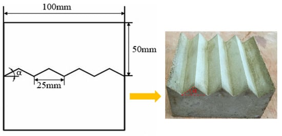
Figure 6.
Schematic diagrams of saw-tooth triangular joint cement mortar specimens (Modified after Xie et al. [70]).
A typical shear stress–shear displacement curve is plotted in Figure 7. It can be observed that the shear stress first rose in a linear way with the increase in shear displacement, and a minor yield stage was present before reaching the peak stress. Subsequently, the shear stress dropped rapidly after its apex and generally leveled off. According to the definitions in Section 2, the peak shear stress τp and the peak shear displacement up were 2.93 MPa and 1.39 mm, respectively. Then, wi can be obtained based on Equation (2), and its relation versus shear stress τ, and the reference line are shown in Figure 8. The w variation between the experimental curve and the reference line exhibited a significant alteration with the increase in w, which is further illustrated in Figure 9. The yield shear stress corresponds to the maximum value of Δw, as shown in Figure 9, where it is determined as 2.42 MPa, accounting for 82.6% of the maximum shear stress.
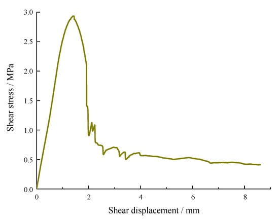
Figure 7.
Shear stress–shear displacement curve from the direct shear test [70].
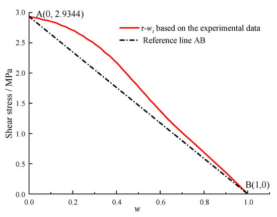
Figure 8.
τ-wi based on the experimental data and the reference line.
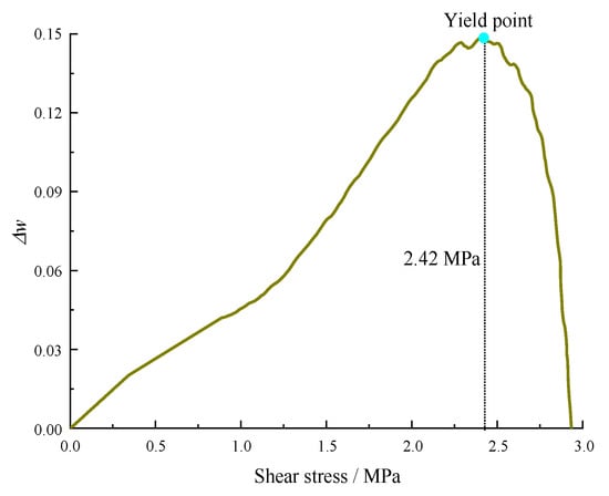
Figure 9.
Determination of the yield point.
Based on the above analysis, the proposed method can better identify the yield shear stress and thus provides a viable approach to characterize the demarcation point between linear elasticity and pre-peak nonelasticity.
3.3. Comparative Analysis
- (1)
- Empirical methods
From the description in Section 2, the ratio of yield stress to peak stress is regarded as 70%–90% [60], 70% [61], and 85% [62], respectively. As the shear displacement occupies one-third of the peak shear displacement, the corresponding stress only accounts for 38.2% of the peak stress. Obviously, the result of the empirical displacement method is far from the true yield point, indicating that this method could produce fairly large errors. The result obtained using our method is close to the approximation ratio (85%) [62].
- (2)
- Shear stiffness method
Figure 10 illustrates the pre-peak stage of the shear stress–shear displacement curve fitted using Equation (1). As described in Section 2, the yield stress can be acquired by the intersection point in Figure 11. However, it can be seen that the two curves only intersect at the original point, indicating that this method cannot identify the yield point of the shear stress–shear displacement curve.
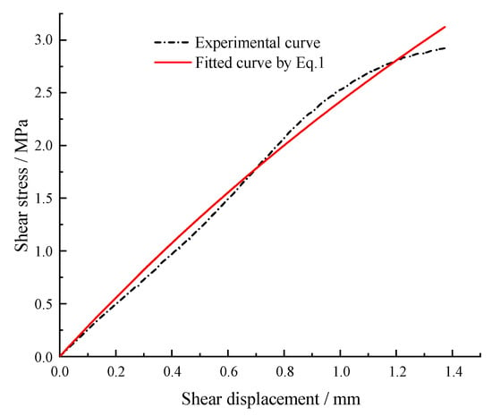
Figure 10.
Pre-peak τ-u curve.
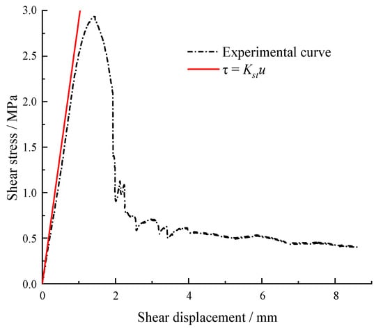
Figure 11.
Determination by the shear stiffness method.
- (3)
- Inflection point method
Figure 12 displays the linear fitting curve of the partial pre-peak stage of the shear–stress displacement curve. As described in Section 2, the yield stress can be determined by the inflection point of the Δτ−u curve in Figure 12b. The yield stress is identified as 2.29 MPa, 78.16% of the peak stress.
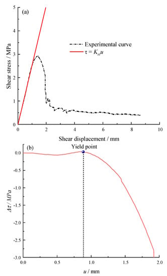
Figure 12.
Determination by the inflection point method, (a) τ-u curve (b) Δτ-u curve.
Based on experimental data from previous publications, Table 1 lists the ratio between the yield stress identified by various methods and the peak stress. It can be noticed that with the implementation of the new method, several ratios of yield stress to peak stress are less than 70%, implying that the empirical stress method may occasionally overestimate the yield stress. With regard to the empirical displacement method, in most cases, the result contradicts the in situ condition. For the shear stiffness method, it is inadequate for predicting the yield stress because the majority of pre-peak stages of experimental shear stress–shear displacement curves do not comply with the hyperbolic distribution. The results determined by the inflection point method exhibit the smallest error (~10%) in comparison to those by the newly proposed method, but it poses a challenge to ascertain the inflection point in an objective manner devoid of any human subjectivity.

Table 1.
Yield point identified by various methods.
4. Discussion
The shear characteristics of rock joints are highly susceptible to external environmental factors, such as the temperature, normal stress, shear velocity, joint roughness coefficient (JRC), etc., which could significantly amplify the non-linear mechanical properties of rocks and thereby lead to the change of the shear yield point. Hence, this section aims to examine the effects of various external environmental factors.
4.1. Effect of the Temperature
The cubic Beishan granite specimens, collected from Gansu Province, China, were axially split to generate an artificial discontinuity. Then, they underwent thermally treatment at temperatures of 100 °C, 200 °C, 300 °C, and 400 °C, respectively [77]. Table 2 and Figure 13 show the detailed stress values and their variation tendency with temperatures, respectively. The yield stress and peak stress overall decrease as the temperature increases from room temperature to 400 ℃, but the proportion of yield stress in peak stress approximately remains relatively constant, as displayed in Figure 13. This manifests that the effect of high temperature (≤400 ℃) on the ratio of yield stress to peak stress of Beishan granite is insignificant. It can also be inferred that very limited micro defects exist in the Beishan granite, thus, this type of rock materials is dense. When subjected to external loads, it is more likely to exhibit elastic−brittle characteristics, which is the reason why τy/τp is larger than 90%.

Table 2.
Yield stress under various temperatures.
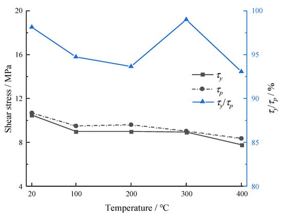
Figure 13.
Yield stresses after thermal treatment (Note: τp data are from Zhao et al. [77]).
4.2. Effect of the Normal Stress
Zhou et al. [78] adopted marble to investigate the effects of undulation and normal stress on shear characteristics. Here, we selected the experimental data at a given dentate height of 3 mm to examine the effect of normal stress on shear mechanical properties, as shown in Table 3 and Figure 14. Both the yield stress and peak stress exhibit an overall increasing variation tendency as the normal stress increases from 10 MPa to 60 MPa, but the proportion of yield stress in peak stress remains relatively constant, with the exception of the condition under a normal stress of 50 MPa, as illustrated in Figure 14. Similarly, the effect of normal stress on the yield point is limited.

Table 3.
Yield stress under various normal stresses.
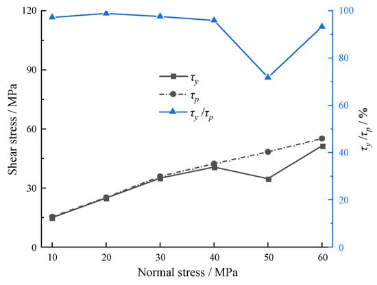
Figure 14.
Yield stresses under different normal stresses (Note: τp data are from Zhou et al. [78]).
4.3. Effect of the Shear Velocity
Marble was chosen by Wang et al. [79] to study the shear behavior subjected to high-velocity impacts. Table 4 and Figure 15 show that both the yield stress and peak stress exhibit an increasing trend with the increasing shear velocity, but the yield point first increases, then decreases within the same shear velocity range. More laboratory tests under high-velocity impacts need to be carried out to systemically examine the relationship between yield stress and shear velocity.

Table 4.
Yield stress under high velocity impact.
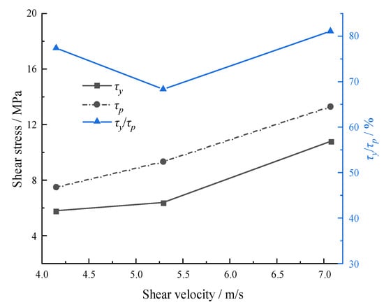
Figure 15.
Yield stresses under high velocity impact (Note: τp data are from Wang et al. [79]).
4.4. Effect of the JRC
Cement mortar was adopted to study the effect of JRC on the shear characteristics of hard−soft interfacial discontinuities [80]. Figure 16 indicates that the yield stress, peak stress, and the ratio of yield stress to peak stress all increase with the increasing JRC, and the corresponding values are listed in Table 5. As the joint surface becomes rougher, the upper and lower parts are more likely to be incorporated together, leading to the enhancement of shear mechanical properties. Hence, the yield point is also increased to resist the external shear stress as the JRC increases.
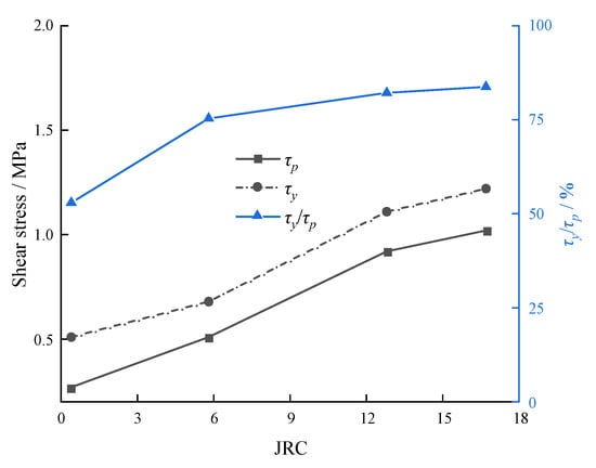
Figure 16.
Yield stresses under the high velocity impact (Note: τp data are from Fan et al. [80]).

Table 5.
Yield stress under various JRC.
4.5. Effect of the Shear Direction
In rock engineering, rock joints are subjected to shear stress along different directions, which can eventually give rise to the anisotropic instability of rock masses. Bao et al. [81] used 3D laser scanning technology to obtain digital information of joint morphology of a tunnel engineering (Figure 17), and a number of rock joints were made by 3D printing. On this basis, the anisotropic shear behavior of rock joints is studied by direct shear tests under a constant normal load. Hence, the resultant data were selected herein to analyze the shear stress variation, as listed in Table 6. The relation between the feature points of shear stress and the shear direction is displayed in Figure 18. It can be observed that both the yield stress and peak stress maximize at the shear direction of 90°, while the percentage of yield stress in peak stress reaches the minimum value at the same direction, indicating that the increasing rate of the yield stress is lower than that of peak stress. When the shear direction exceeds the critical value (90°), the yield stress and peak stress increase first, then decrease, but the percentage of yield stress in peak stress performs an inverse tendency.
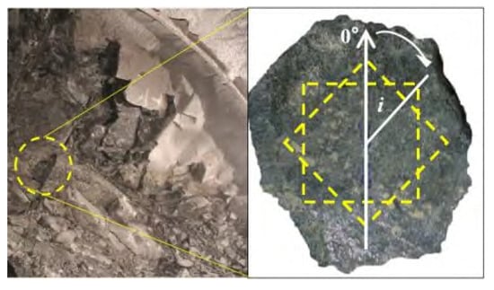
Figure 17.
Schematic diagram of the selected rock joints [81].

Table 6.
Yield stress under different shear directions.
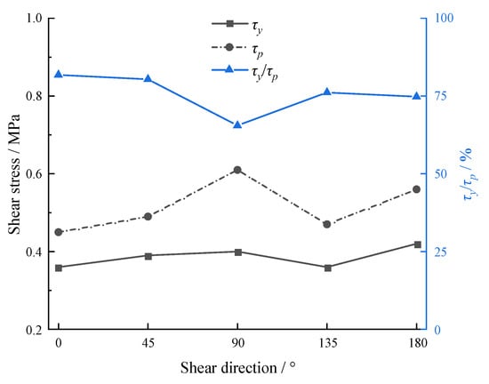
Figure 18.
Yield stresses under different shear directions (Note: τp data are from Bao et al. [81]).
5. Conclusions
Based on the displacement reduction coefficient, a new method is proposed in this paper to accurately identify the yield point of stress–shear displacement curves. In this method, a reference line connected by points A (0, τp) and B (1, 0) is introduced. The yield stress can then be determined as the displacement reduction coefficient difference between the experimental shear–stress displacement curve and the reference line maximizes. The effectiveness and precision are validated by many experimental data from published papers. Compared with previous methods, this method can enhance objectivity and effectively reduce human interference. Furthermore, the effects of external environmental factors except JRC on the yield stress are limited, which demonstrates that the yield stress of rock materials is dependent on in situ lithology to a large extent, and can be significantly affected by the joint surface roughness.
Author Contributions
Z.H.: methodology, data curation, writing and editing, funding acquisition. S.X.: conceptualization, review and editing. H.L.: investigation, funding acquisition. H.D.: investigation. D.L.: supervision. All authors have read and agreed to the published version of the manuscript.
Funding
The authors would like to acknowledge the financial support from the Postgraduate Research and Practice Innovation Program of Jiangsu Province (No. KYCX21_0119), and Project (42277175) supported by National Natural Science Foundation of China.
Data Availability Statement
Not applicable.
Conflicts of Interest
The authors declare no conflict of interest.
References
- Develi, K. Computation of direction dependent joint surface parameters through the algorithm of triangular prism surface area method: A theoretical and experimental study. Int. J. Solids Struct. 2020, 202, 895–911. [Google Scholar] [CrossRef]
- Xie, H.; Zhu, J.; Zhou, T.; Zhang, K.; Zhou, C. Conceptualization and preliminary study of engineering disturbed rock dynamics. Geomech. Geophys. Geo-Energy Geo-Resour. 2020, 6, 34. [Google Scholar] [CrossRef]
- Han, Z.; Li, D.; Li, X. Dynamic mechanical properties and wave propagation of composite rock-mortar specimens based on SHPB tests. Int. J. Min. Sci. Technol. 2022, 32, 793–806. [Google Scholar] [CrossRef]
- Han, Z.; Li, D.; Li, X. Effects of axial pre-force and loading rate on Mode I fracture behavior of granite. Int. J. Rock Mech. Min. Sci. 2022, 157, 105172. [Google Scholar] [CrossRef]
- Xie, S.J.; Han, Z.Y.; Chen, Y.F.; Wang, Y.X.; Zhao, Y.L.; Lin, H. Constitutive modeling of rock materials considering the void compaction characteristics. Arch. Civ. Mech. Eng. 2022, 22, 60. [Google Scholar] [CrossRef]
- Wen, G.P.; Hu, J.H.; Jie, W.; Yang, D.J.; Rui, X. Characteristics of stress, crack evolution, and energy conversion of anchored granite containing two preexisting fissures under uniaxial compression. Bull. Eng. Geol. Environ. 2023, 82, 1–14. [Google Scholar] [CrossRef]
- Xie, H.P.; Sun, H.Q.; Ju, Y.; Feng, Z.G. Study on generation of rock fracture surfaces by using fractal interpolation. Int. J. Solids Struct. 2001, 38, 5765–5787. [Google Scholar] [CrossRef]
- Singh, H.K.; Basu, A. Evaluation of existing criteria in estimating shear strength of natural rock discontinuities. Eng. Geol. 2018, 232, 171–181. [Google Scholar] [CrossRef]
- Elmo, D.; Donati, D.; Stead, D. Challenges in the characterisation of intact rock bridges in rock slopes. Eng. Geol. 2018, 245, 81–96. [Google Scholar] [CrossRef]
- Yu, W.J.; Li, K.; Liu, Z.; An, B.F.; Wang, P.; Wu, H. Mechanical characteristics and deformation control of surrounding rock in weakly cemented siltstone. Environ. Earth Sci. 2021, 80, 1–5. [Google Scholar] [CrossRef]
- Asadizadeh, M.; Hossaini, M.F.; Moosavi, M.; Masoumi, H.; Ranjith, P.G. Mechanical characterisation of jointed rock-like material with non-persistent rough joints subjected to uniaxial compression. Eng. Geol. 2019, 260, 105224. [Google Scholar] [CrossRef]
- Salmi, E.F.; Nazem, M.; Karakus, M. Numerical analysis of a large landslide induced by coal mining subsidence. Eng. Geol. 2017, 217, 141–152. [Google Scholar] [CrossRef]
- Lin, Q.B.; Cao, P.; Wen, G.P.; Meng, J.J.; Cao, R.H.; Zhao, Z.Y. Crack coalescence in rock-like specimens with two dissimilar layers and pre-existing double parallel joints under uniaxial compression. Int. J. Rock Mech. Min. Sci. 2021, 139, 104621. [Google Scholar] [CrossRef]
- Cai, W.Q.; Zhu, H.H.; Liang, W.H. Three-dimensional tunnel face extrusion and reinforcement effects of underground excavations in deep rock masses. Int. J. Rock Mech. Min. Sci. 2022, 150, 104999. [Google Scholar] [CrossRef]
- Liu, J.; Wang, J. Numerical study of crack propagation in an indented rock specimen. Comput. Geotech. 2018, 96, 1–11. [Google Scholar] [CrossRef]
- Han, Z.; Li, D.; Zhou, T.; Zhu, Q.; Ranjith, P.G. Experimental study of stress wave propagation and energy characteristics across rock specimens containing cemented mortar joint with various thicknesses. Int. J. Rock Mech. Min. Sci. 2020, 131, 104352. [Google Scholar] [CrossRef]
- Chen, W.; Wan, W.; Zhao, Y.L.; Peng, W.Q. Experimental study of the crack predominance of rock-like material containing parallel double fissures under uniaxial compression. Sustainability 2020, 12, 5188. [Google Scholar] [CrossRef]
- Zheng, C.S.; Jiang, B.Y.; Xue, S.; Chen, Z.W.; Li, H. Coalbed methane emissions and drainage methods in underground mining for mining safety and environmental benefits: A review. Process. Saf. Environ. 2019, 127, 103–124. [Google Scholar] [CrossRef]
- Sow, D.; Carvajal, C.; Breul, P.; Peyras, L.; Rivard, P.; Bacconnet, C.; Ballivy, G. Modeling the spatial variability of the shear strength of discontinuities of rock masses: Application to a dam rock mass. Eng. Geol. 2017, 220, 133–143. [Google Scholar] [CrossRef]
- Zhou, X.; Xie, Y.J.; Long, G.C.; Li, J.T. Effect of surface characteristics of aggregates on the compressive damage of high-strength concrete based on 3D discrete element method. Constr. Build. Mater. 2021, 301, 124101. [Google Scholar] [CrossRef]
- Xie, S.; Lin, H.; Wang, Y.; Chen, Y.; Xiong, W.; Zhao, Y.; Du, S. A statistical damage constitutive model considering whole joint shear deformation. Int. J. Damage Mech. 2020, 29, 988–1008. [Google Scholar] [CrossRef]
- Babanouri, N.; Asadizadeh, M.; Hasan-Alizade, Z. Modeling shear behavior of rock joints: A focus on interaction of influencing parameters. Int. J. Rock Mech. Min. Sci. 2020, 134, 104449. [Google Scholar] [CrossRef]
- Xie, S.; Lin, H.; Cheng, C.; Chen, Y.; Wang, Y.; Zhao, Y.; Yong, W. Shear strength model of joints based on Gaussian smoothing method and macro-micro roughness. Comput. Geotech. 2022, 143, 104605. [Google Scholar] [CrossRef]
- Xie, S.; Han, Z.; Zhou, T. A semiempirical constitutive relationship for rocks under uniaxial compression considering the initial damage recovery. Fatigue Fract. Eng. Mater. Struct. 2023, 46, 1300–1313. [Google Scholar] [CrossRef]
- Zhu, C.G.; Long, S.C.; Zhang, J.X.; Wu, W.H.; Zhang, L.Y. Time series multi-sensors of interferometry synthetic aperture radar for monitoring ground deformation. Front. Environ. Sci. 2022, 10, 952. [Google Scholar] [CrossRef]
- Pirzada, M.A.; Bahaaddini, M.; Moradian, O.; Roshan, H. Evolution of contact area and aperture during the shearing process of natural rock fractures. Eng. Geol. 2021, 291, 106236. [Google Scholar] [CrossRef]
- Renaud, S.; Bouaanani, N.; Miquel, B. Numerical simulation of experimentally shear-tested contact specimens from existing dam joints. Comput. Geotech. 2020, 125, 103630. [Google Scholar] [CrossRef]
- Singh, H.K.; Basu, A. Shear behaviors of ‘real’ natural un-matching joints of granite with equivalent joint roughness coefficients. Eng. Geol. 2016, 211, 120–134. [Google Scholar] [CrossRef]
- Saadat, M.; Taheri, A. A cohesive discrete element based approach to characterizing the shear behavior of cohesive soil and clay-infilled rock joints. Comput. Geotech. 2019, 114, 103109. [Google Scholar] [CrossRef]
- Xin, J.; Jiang, Q.; Liu, Q.; Zheng, H.; Li, S.J. A shear constitutive model and experimental demonstration considering dual void portion and solid skeleton portion of rock. Eng. Fract. Mech. 2023, 281, 109066. [Google Scholar] [CrossRef]
- Zhou, X.; Xie, Y.J.; Long, G.C.; Zeng, X.H.; Li, J.T.; Yao, L.; Jiang, W.H.; Pan, Z.L. DEM analysis of the effect of interface transition zone on dynamic splitting tensile behavior of high-strength concrete based on multi-phase model. Cem. Concr. Res. 2021, 149, 106577. [Google Scholar] [CrossRef]
- Zhao, Y.L.; Luo, S.L.; Wang, Y.X.; Wang, W.J.; Zhang, L.Y.; Wan, W. Numerical analysis of karst water inrush and a criterion for establishing the width of water-resistant rock pillars. Mine Water Environ. 2017, 36, 508–519. [Google Scholar] [CrossRef]
- Yuan, Z.G.; Zhao, J.T.; Li, S.Q.; Jiang, Z.H.; Huang, F. A unified solution for surrounding rock of roadway considering seepage, dilatancy, strain-softening and intermediate principal stress. Sustainability 2022, 14, 8099. [Google Scholar] [CrossRef]
- Wu, H.; Jia, Q.; Wang, W.J.; Zhang, N.; Zhao, Y.M. Experimental test on nonuniform deformation in the tilted strata of a deep coal mine. Sustainability 2021, 13, 13280. [Google Scholar] [CrossRef]
- Xie, S.; Han, Z.; Hu, H.; Lin, H. Application of a novel constitutive model to evaluate the shear deformation of discontinuity. Eng. Geol. 2022, 304, 106693. [Google Scholar] [CrossRef]
- Zou, S.H.; Li, K.Q.; Han, Q.Y.; Yu, C.W. Numerical simulation of the dynamic formation process of fog-haze and smog in transport tunnels of a hot mine. Indoor Built Environ. 2017, 26, 1062–1069. [Google Scholar] [CrossRef]
- Sun, Z.; Niu, D.T.; Wang, X.Q.; Zhang, L.; Luo, D.M. Bond behavior of coral aggregate concrete and corroded Cr alloy steel bar. J. Build Eng. 2022, 61, 105294. [Google Scholar] [CrossRef]
- Sun, Z.; He, W.D.; Niu, D.T.; Zhang, L.; Su, L.; Wang, X.Q. Resistivity prediction model for basalt-polypropylene fiber-reinforced concrete. Buildings 2023, 13, 84. [Google Scholar] [CrossRef]
- Haghgouei, H.; Kargar, A.R.; Amini, M.; Esmaeili, K. An analytical solution for analysis of toppling-slumping failure in rock slopes. Eng. Geol. 2020, 265, 105396. [Google Scholar] [CrossRef]
- Wu, Y.Q.; Zhou, Y.S. Hybrid machine learning model and Shapley additive explanations for compressive strength of sustainable concrete. Constr. Build. Mater. 2022, 330, 127298. [Google Scholar] [CrossRef]
- Wu, Y.Q.; Zhou, Y.S. Prediction and feature analysis of punching shear strength of two-way reinforced concrete slabs using optimized machine learning algorithm and Shapley additive explanations. Mech. Adv. Mater. Struc. 2022. [Google Scholar] [CrossRef]
- Lin, Q.B.; Cao, P.; Meng, J.J.; Cao, R.H.; Zhao, Z.Y. Strength and failure characteristics of jointed rock mass with double circular holes under uniaxial compression: Insights from discrete element method modelling. Theor. Appl. Fract. Mec. 2020, 109, 102692. [Google Scholar] [CrossRef]
- Thirukumaran, S.; Indraratna, B. A review of shear strength models for rock joints subjected to constant normal stiffness. J. Rock Mech. Geotech. Eng. 2016, 8, 405–414. [Google Scholar] [CrossRef]
- Zhao, Y.L.; Tang, J.Z.; Chen, Y.; Zhang, L.Y.; Wang, W.J.; Wan, W.; Liao, J.P. Hydromechanical coupling tests for mechanical and permeability characteristics of fractured limestone in complete stress-strain process. Environ. Earth Sci. 2017, 76, 1–18. [Google Scholar] [CrossRef]
- Patton, F.D. Multiple modes of shear failure in rock. In Proceedings of the 1st Congress of International Society of Rock Mechanics, Lisbon, Portugal, 25 September–1 October 1966. [Google Scholar]
- Cai, W.; Zhu, H.; Liang, W. Three-dimensional stress rotation and control mechanism of deep tunneling incorporating generalized Zhang–Zhu strength-based forward analysis. Eng. Geol. 2022, 308, 106806. [Google Scholar] [CrossRef]
- Zhao, Y.L.; Zhang, C.S.; Wang, Y.X.; Lin, H. Shear-related roughness classification and strength model of natural rock joint based on fuzzy comprehensive evaluation. Int. J. Rock Mech. Min. Sci. 2021, 137, 104550. [Google Scholar] [CrossRef]
- Barton, N.; Choubey, V. The shear strength of rock joints in theory and practice. Rock Mech. 1977, 10, 1–54. [Google Scholar] [CrossRef]
- Ulusay, R. The ISRM Suggested Methods for Rock Characterization, Testing and Monitoring: 2007–2014; Springer: Berlin/Heidelberg, Germany, 2014. [Google Scholar]
- Xie, S.; Lin, H.; Duan, H. A novel criterion for yield shear displacement of rock discontinuities based on renormalization group theory. Eng. Geol. 2023, 314, 107008. [Google Scholar] [CrossRef]
- Xie, S.; Lin, H.; Chen, Y. New constitutive model based on disturbed state concept for shear deformation of rock joints. Arch. Civ. Mech. Eng. 2022, 23, 26. [Google Scholar] [CrossRef]
- Li, Y.; Oh, J.; Mitra, R.; Hebblewhite, B. A constitutive model for a laboratory rock joint with multi-scale asperity degradation. Comput. Geotech. 2016, 72, 143–151. [Google Scholar] [CrossRef]
- Oh, J.; Cording, E.J.; Moon, T. A joint shear model incorporating small-scale and large-scale irregularities. Int. J. Rock Mech. Min. Sci. 2015, 76, 78–87. [Google Scholar] [CrossRef]
- Zhao, Y.L.; Liu, Q.; Zhang, C.S.; Liao, J.; Lin, H.; Wang, Y.X. Coupled seepage-damage effect in fractured rock masses: Model development and a case study. Int. J. Rock Mech. Min. Sci. 2021, 144, 104822. [Google Scholar] [CrossRef]
- Feng, W.L.; Zou, D.J.; Wang, T.; Qiao, C.S.; Xu, S.F. Study on a nonlinear shear damage constitutive of structural plane and application of discrete element. Comput. Geotech. 2023, 155, 105190. [Google Scholar] [CrossRef]
- Parrinello, F.; Failla, B.; Borino, G. Cohesive–frictional interface constitutive model. Int. J. Solids Struct. 2009, 46, 2680–2692. [Google Scholar] [CrossRef]
- Cai, W.; Zhu, H.; Liang, W.; Wang, X.; Su, C.; Wei, X. A post-peak dilatancy model for soft rock and its application in deep tunnel excavation. J. Rock Mech. Geotech. Eng. 2023, 15, 683–701. [Google Scholar] [CrossRef]
- Tong, D.; Yi, X.-W.; Tan, F.; Jiao, Y.Y.; Liang, J. Three-dimensional numerical manifold method for heat conduction problems with a simplex integral on the boundary. Sci. China Technol. Sci. 2023. [Google Scholar]
- Leong, E.C.; Randolph, M.F. A model for rock interfacial behavior. Rock Mech. Rock Eng. 1992, 25, 187–206. [Google Scholar] [CrossRef]
- Goodman, R. The mechanical properties of joints. In Proceedings of the 3rd Int Congr International Society of Rock Mechanics, Denver, CO, USA, 1–7 September 1974; pp. 1–7. [Google Scholar]
- Xiao, W.; Dui, G.; Chen, T.; Ren, Q. A study of constitutive model coupling dilatancy and degradation for jointed rock. Chin. J. Rock Mech. Eng. 2009, 28, 2535–2543. [Google Scholar]
- Sun, W.; Gao, J.; Zhang, W.; Yang, K. Experimental study on the shear mechanical properties of discontinuities in rock masses. China Water Transp. 2008, 8, 159–160. [Google Scholar]
- Lee, S. Stability around underground Openings in Rock with Dilative, Non-Persistent and Multi-Scale Wavy Joints Using a Discrete Element Method; University of Illinois at Urbana-Champaign: Chicago, IL, USA, 2003. [Google Scholar]
- Xu, L.; Ren, Q. A new constitutive model for rock discontinuities. Rock Soil Mech. 2011, 32, 217–224. [Google Scholar] [CrossRef]
- Gens, A.; Carol, I.; Alonso, E.E. A constitutive model for rock joints formulation and numerical implementation. Comput. Geotech. 1990, 9, 3–20. [Google Scholar] [CrossRef]
- Kulhawy, F.H. Stress deformation properties of rock and rock discontinuities. Eng. Geol. 1975, 9, 327–350. [Google Scholar] [CrossRef]
- Bandis, S.C.; Lumsden, A.C.; Barton, N.R. Fundamentals of rock joint deformation. Int. J. Rock Mech. Min. Sci. 1983, 20, 249–268. [Google Scholar] [CrossRef]
- Xie, S.; Lin, H.; Chen, Y.; Yong, R.; Xiong, W.; Du, S. A damage constitutive model for shear behavior of joints based on determination of the yield point. Int. J. Rock Mech. Min. Sci. 2020, 128, 104269. [Google Scholar] [CrossRef]
- Xie, S.; Han, Z.; Shu, R.; Chen, Y.; Feng, F. A new method to determine the crack closure stress based on stress difference. Theor. Appl. Fract. Mec. 2022, 119, 103337. [Google Scholar] [CrossRef]
- Xie, S.J.; Lin, H.; Wang, Y.X.; Cao, R.H.; Yong, R.; Du, S.G.; Li, J.T. Nonlinear shear constitutive model for peak shear-type joints based on improved Harris damage function. Arch. Civ. Mech. Eng. 2020, 20, 1–14. [Google Scholar] [CrossRef]
- Papaliangas, T.; Hencher, S.R.; Lumsden, A.C.; Manolopoulou, S. The effect of frictional fill thickness on the shear strength of rock discontinuities. Int. J. Rock Mech. Min. Sci. 1993, 30, 81–91. [Google Scholar] [CrossRef]
- Grasselli, G. Manuel Rocha Medal recipient-Shear strength of rock joints based on quantified surface description. Rock Mech. Rock Eng. 2006, 39, 295–314. [Google Scholar] [CrossRef]
- Nasir, O.; Fall, M. Shear behaviour of cemented pastefill-rock interfaces. Eng. Geol. 2008, 101, 146–153. [Google Scholar] [CrossRef]
- Bahaaddini, M. Effect of boundary condition on the shear behaviour of rock joints in the direct shear test. Rock Mech. Rock Eng. 2017, 50, 1141–1155. [Google Scholar] [CrossRef]
- Ge, Y.F.; Tang, H.M.; Eldin, M.; Wang, L.Q.; Wu, Q.; Xiong, C.R. Evolution process of natural rock joint roughness during direct shear tests. Int. J. Geomech. 2017, 17, E4016013. [Google Scholar] [CrossRef]
- Ong, D.E.L.; Choo, C.S. Assessment of non-linear rock strength parameters for the estimation of pipe jacking forces. Part 1. Direct shear testing and backanalysis. Eng. Geol. 2018, 244, 159–172. [Google Scholar] [CrossRef]
- Zhao, Z.H.; Dou, Z.H.; Xu, H.R.; Liu, Z.N. Shear behavior of Beishan granite fractures after thermal treatment. Eng. Fract. Mech. 2019, 213, 223–240. [Google Scholar] [CrossRef]
- Zhou, H.; Cheng, G.T.; Zhu, Y.; Chen, J.; Lu, J.J.; Cui, G.J.; Yang, P.Q. Experimental study of shear deformation characteristics of marble dentate joints. Rock Soil Mech. 2019, 40, 852–860. [Google Scholar] [CrossRef]
- Wang, F.; Xia, K.; Yao, W.; Wang, S.; Wang, C.; Xiu, Z. Slip behavior of rough rock discontinuity under high velocity impact: Experiments and models. Int. J. Rock Mech. Min. Sci. 2021, 144, 104831. [Google Scholar] [CrossRef]
- Fan, X.; Deng, Z.Y.; Cui, Z.M.; He, Z.M.; Lin, H. A new peak shear strength model for soft-hard joint. Rock Soil Mech. 2021, 42, 1861–1870. [Google Scholar] [CrossRef]
- Bao, H.; Xu, X.; Lan, H.; Yan, C.; Xu, J. Stiffness model of rock joint by considering anisotropic morphology. J. Traffic Transp. Eng. 2021, 11, 1–18. (In Chinese) [Google Scholar]
Disclaimer/Publisher’s Note: The statements, opinions and data contained in all publications are solely those of the individual author(s) and contributor(s) and not of MDPI and/or the editor(s). MDPI and/or the editor(s) disclaim responsibility for any injury to people or property resulting from any ideas, methods, instructions or products referred to in the content. |
© 2023 by the authors. Licensee MDPI, Basel, Switzerland. This article is an open access article distributed under the terms and conditions of the Creative Commons Attribution (CC BY) license (https://creativecommons.org/licenses/by/4.0/).