Article

Failure Mechanism and Stability Control of Soft Roof in Advance Support Section of Mining Face

1
School of Energy and Mining Engineering, China University of Mining and Technology (Beijing), Beijing 100083, China
2
CCTEG Wuhan Engineering Company, Wuhan 430064, China
*
Authors to whom correspondence should be addressed.
Minerals 2023, 13(2), 178; https://doi.org/10.3390/min13020178
Submission received: 4 January 2023 / Revised: 20 January 2023 / Accepted: 24 January 2023 / Published: 26 January 2023
(This article belongs to the Topic Mining Safety and Sustainability)

Abstract

:
There is a great risk of roof falls in the advance support section of the mining face (ASSoMF), and it is difficult to control the roof. Based on the soft roof of Lijiahao coal mine, this paper studies the stress distribution of the ASSoMF and the space-time evolution of the surrounding rock plastic zone by using theoretical analysis and numerical simulation, and reveals its failure mechanism. Based on the control effect of support resistance on plastic zone, it is proposed that the advance support should mainly adapt to the roadway deformation. Advance equipment without repeated support for mechanized movement has been developed, and the support timing analysis and strength check have been carried out. Results show that the roadway at ASSoMF is in a non-uniform stress field, the confining pressure ratio reaches 1.5~7, and the surrounding rock forms asymmetric failure; the principal stress direction deflects, the angle between it and the vertical direction is about 10°~25°, and the plastic zone of the surrounding rock also rotates to the roadway roof. The proposed equipment can adapt to the characteristics of an unsymmetrical large deformation of a soft roof, and can effectively bear the roof load and maintain the stability of the roadway.

1. Introduction

The surrounding rock of the roadway in the advance support section of the mining face (ASSoMF) is affected by the superposition of the original rock stress, the side-mining stress, and the advance abutment stress [1,2,3,4]. The surrounding rock deformation and damage extent are large, and the risk of roof fall is high [5,6,7]. At the same time, this area is also the throat of transportation, pedestrians, and ventilation [8,9]. So, it is the key point of roadway-surrounding rock maintenance [10,11,12], but its failure mechanism is not yet clear [13]. At present, a single hydraulic prop and advance hydraulic support are mostly used for ASSoMF [14,15]. The problem of safe and efficient transport of the advance support body and repeatedly supporting the roof and bolt (cable) support system has not been solved.
In view of the above problems, many scholars have studied the failure mechanism and control technology of the surrounding rock of ASSoMF. In terms of active support, Guo et al. [16,17] established a mechanical model of advance support by analyzing the distribution law of abutment stress in the thick and hard roof, and proposed to use the cable to replace the single hydraulic prop. Chai et al. [18,19] established a model of support strength and roof subsidence, and proposed the calculation method of support strength and support body shrinkage, which provided a certain reference for the determination of support parameters of ASSoMF. Yao [20,21], Zhou [22] et al. put forward the one-time active support technology of a cable in the full life cycle of the roadway by establishing the prediction model of surrounding rock deformation affected by mining in a single-side goaf roadway and a solid coal roadway. In terms of passive support, Zhao [23], Lai et al. [24] studied the stress and deformation of the surrounding rock at ASSoMF, and proposed that the advance support should be of non-equal strength, based on the stress distribution and deformation characteristics of the surrounding rock. Zhang et al. [25] studied the mechanical properties of surrounding rock supported by the coupling of an advance hydraulic support group and anchor bolt (cable), and proposed a support strategy of unequal strength. Xu et al. [2,26] put forward the adaptive support theory of advance support and the movement technology of hydraulic support to solve the problem wherein the roof and anchor system of roadway are damaged by repeated support; this improved the ability of the advance support to adapt to the surrounding rock. Wang et al. [27] developed the cross door-type circulating advance support equipment, and proposed the cooperative support principle of active support + advance reinforcement support.
From the above analysis, it can be seen that current research focuses on the coupling between the deformation of the surrounding rock and the support body, but the difference in geological conditions makes the deformation law of the surrounding rock vary greatly [28,29]. The failure shapes of surrounding rock of the roadway at ASSoMF are rarely studied, and the corresponding safe and efficient movement technology of advance support needs to be further studied.

2. Failure Mechanism of Surrounding Rock of Roadway at ASSoMF

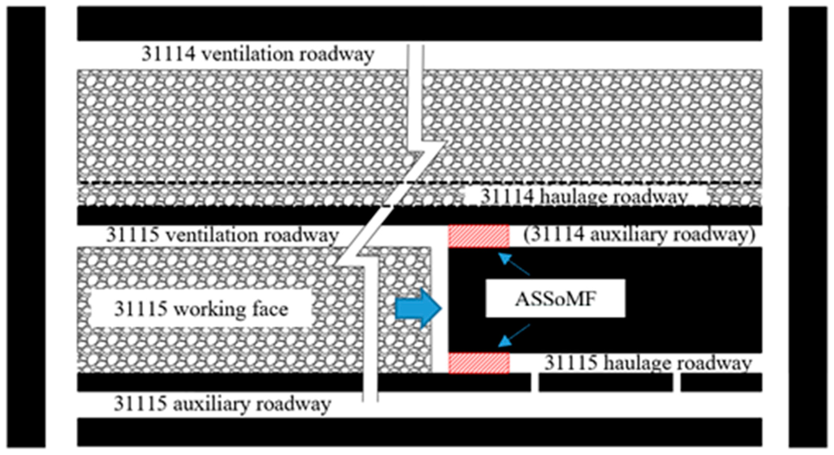
2.1. Background of Lijiahao Coal Mine

Lijiahao coal mine is located at Dongsheng Coalfield, Inner Mongolia, China. The coal seam is shallow, and the bedrock is thick. The roof and floor rocks are mainly sandy mudstone and siltstone, with low rock strength and poor stability. The ratio of horizontal stress to vertical stress in the regional stress field is about 1.2. The geological drilling column is shown in Figure 1 [13]. The 31115 working face of coal seam 31 has an average coal thickness of 6 m. The thickness of the coal seam in the whole working face is relatively stable, with an average buried depth of about 220 m. The working face is arranged with two roadways, that is, two roadways are excavated at the same time while driving, one of which is reserved to serve the next adjacent working face, as shown in Figure 2.

2.2. Construction and Excavation of Numerical Simulation Model

Flac 3D software is used to simulate the mining of the working face of Lijiahao coal mine. The Mohr Coulomb model is used as the constitutive model. The goaf is filled with double-yield model [30], and the relevant mechanical parameters are shown in Table 1. The displacement around the model and the bottom is fixed, and 3.9 MPa equivalent load is applied above the model to compensate for the vertical stress of the overburden. Gravity is applied to the model. The model grid is a 5 m/grid in which the surrounding rock of the roadway at ASSoMF is refined to a 0.5 m/grid; the numerical simulation model is shown in Figure 3, the physical and mechanical parameters of each rock stratum are shown in Table 2, and the lateral pressure coefficient is taken as 1.2.
The excavation process of this numerical simulation is as follows. Step (1): An in situ stress-state is applied, and an initial equilibrium is reached. Step (2): The 31114 working face and haulage roadway are extracted (from 100 m to 900 m) to obtain the stress state at the position of the 31115 ventilation roadway (primary mining influence). Step (3): The 31115 working face is excavated (from 100 m to 600 m) to obtain the stress state at the position of the 31115 ventilation roadway (secondary mining influence) and haulage roadway. Step (4) The initial equilibrium state is restored, the 31114 haulage roadway, 31115 ventilation roadway and haulage roadway are extracted, and the equilibrium state is calculated to. Step (5): The 31114 working face is extracted (from 100 m to 900 m) to obtain the plastic zone status of the 31115 ventilation roadway (primary mining influence). Step (6): The 31115 working face is extracted (from 100 m to 600 m) to obtain the plastic zone status of 31115 ventilation roadway (secondary mining influence) and haulage roadway.
Because the surrounding rock stress will be released after the roadway is excavated, the stress obtained by numerical simulation is often too small. Through the above excavation process, this problem can be avoided, and a more accurate stress state and plastic zone state of the roadway can be obtained.

2.3. Regional Stress Distribution Law of Mining Roadway

After the completion of the previous working face, the stress field at the roadway position of the next working face will be disturbed. After the implementation of Step 2, the distribution characteristics of stress field at the side of goaf are shown in Figure 4. It can be seen that the vertical stress at the goaf is about 0.6 MPa; with the distance away from the goaf, the maximum principal stress (σ1), minimum principal stress (σ3) and intermediate principal stress (σ2) showed a trend of first increasing and then decreasing. About 5 m away from the goaf, each principal stress and vertical stress reach their peak values, of which the maximum principal stress peak value is about 17 MPa and the minimum principal stress peak value is about 7.5 MPa. The stress concentration at this point may be due to the fracture of the side roof of the goaf, and the overburden rock load is carried by the surrounding rock. With the distance away from the goaf, the confining pressure ratio η (σ1/σ3) gradually decreases from a peak value of about 3.7. The confining pressure ratio at the 31115 ventilation roadway is about 1.5, and the confining pressure ratio is reduced to about 1.2 in the area 35 m away from the side of goaf.
Near the goaf, the direction of the regional stress field has also changed, as shown in Figure 5 (purple curve). The maximum principal stress direction is rotated from the horizontal direction in the original rock stress field to the vertical direction. With the distance away from the goaf, the maximum principal stress gradually rotates to the horizontal direction, and the maximum principal stress at the roadway position is about 45° from the vertical direction.
After the implementation of Step 3, the stress distribution characteristics of the 31115 ventilation roadway (gob-side roadway) are obtained by simulation, as shown in Figure 6. The principal stress and vertical stress in front of the working face show a trend of increasing first and then decreasing. The peak stress appears at about 10 m in front of the working face. The maximum principal stress peak is about 15 MPa, and the minimum principal stress peak is about 8 MPa. The peak value of the confining pressure ratio near the working face reaches about 7.5, and the area within 20 m ahead of working face is obviously controlled by the advance abutment stress field. The confining pressure ratio gradually decreases with the distance away from the working face. The confining pressure ratio is about 1.5 at the front of the working face between 20–100 m. This is consistent with the distribution characteristics of the side stress field of the goaf, which indicates that the area 20 m in front of the working face is mainly controlled by the side-mining stress field.
The angle between the maximum principal stress direction and the vertical direction near the working face is about 10~30°. With the distance away from the working face, the angle gradually increases, and returns to the control of the side stress field of the goaf; then, the angle is stable at about 45°, as shown in Figure 5 (orange curve).
After the implementation of Step 4, the axial stress distribution characteristics of the 31115 haulage roadway (a solid coal roadway) are shown in Figure 7. The principal stresses and vertical stresses also show a trend of increasing first and then decreasing. At about 5 m in front of the working face, each stress value reaches the maximum; the maximum principal stress peak value is about 12 MPa, and the minimum principal stress peak value is about 7 MPa, both of which are smaller than the abutment stress peak value of the gob-side roadway. The confining pressure ratio near the working face also reached about 7.5, and in the area 10 m away from the working face dropped to about 1.2, indicating that the influence range of the advance abutment stress of the solid coal roadway is smaller than that of the gob-side roadway.
Near the working face, the direction of the maximum principal stress deflects at an angle of 10° with the vertical direction. As it is far away from the working face, the direction of the maximum principal stress gradually deflects to the horizontal direction and returns to the original rock stress state, as shown in Figure 5 (red curve).

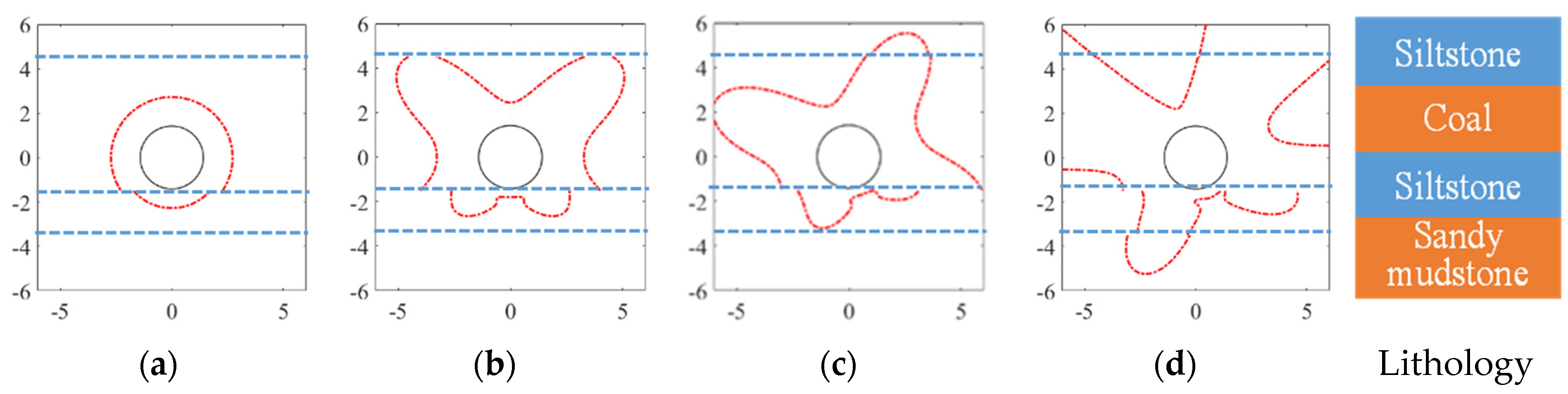
2.4. Space-Time Evolution Law of Surrounding Rock Plastic Zone

After the implementation of Step 5, the distribution characteristics of surrounding rock plastic zones at different locations of the 31115 ventilation roadway are shown in Figure 8. It can be seen that the shape and range of the surrounding rock plastic zone at 200 m and 700 m behind the working face are basically the same. The range of the roof plastic zone at the side of the coal wall (right) is larger than that at the side of the coal pillar (left), both of which are distributed asymmetrically. The extent of the roof plastic zone is about 3 m. The mining of the previous working face caused the stress field of the surrounding rock of the roadway to be disturbed. The confining pressure ratio reached about 1.5, and the direction of the main stress also deflected. Therefore, the plastic zone of the surrounding rock of the roadway presented asymmetry. The surrounding rocks of roadways at different locations are affected by the same mining disturbance, so the plastic zone is basically the same.
After the implementation of Step 6, the distribution of surrounding rock plastic zone at ASSoMF of the 31115 ventilation roadway is shown in Figure 9. The roadway is affected by the side-mining stress of the previous working face and the advance abutment stress of this working face. The plastic zone of the surrounding rock continues to expand on the original basis. The plastic zone extent of the roadway roof and the side of the coal wall near the working face increases sharply. The shape and range of the plastic zone of the surrounding rock do not change much in the area 10 m ahead of the working face and beyond. As a whole, the plastic zone of roadway-surrounding rock is still distributed asymmetrically, and the plastic zone of roof is mainly distributed on the side of coal wall (right side). This shows that on the basis of side-mining stress disturbance, although the superposition of advance abutment stress has adjusted the direction of principal stress and increased the confining pressure ratio, the failure direction of the plastic zone of the roof-surrounding rock has basically not changed, which only causes an increase in the plastic zone range. In the area beyond the disturbance of advance abutment stress, the plastic zone of the roadway-surrounding rock is still controlled by the side-mining stress field.
Both sides of the 31115 haulage roadway are solid coal which is only affected by mining disturbance of the 31115 working face. After the implementation of Step 6, the direction of principal stress changes from horizontal to vertical, the confining pressure ratio increases sharply, and the surrounding rock plastic zone is also developed, as shown in Figure 10. The surrounding rock plastic zone is still distributed asymmetrically near the working face, within the range of about 10 m ahead of the working face. The roof-surrounding rock plastic zone is mainly developed at the side of the coal pillar (right side), and the side plastic zone is mainly developed at the side of the coal wall (left side). With the distance away from the working face, the surrounding rock plastic zone gradually changes from asymmetric distribution to symmetric distribution. The roof, floor and the two sides’ plastic zone of the roadway are symmetrically distributed, with the center line of the roadway at 20 m ahead of the working face.

2.5. Failure Mechanism of Surrounding Rock in Non-Uniform Stress Field

When the surrounding rock of roadway is in a non-uniform stress field (confining pressure ratio η ≠ 1), the plastic zone of surrounding rock will gradually transform from circular to elliptical and butterfly shape with an increase or decrease in the confining pressure ratio. The plastic zone of butterfly leaf is located in the direction of the bisector of the angle between the maximum principal stress and the minimum principal stress. When the stress direction deflects, the plastic zone of butterfly leaf will also deflect accordingly [31,32].
According to the forementioned simulation results, the η of the 31115 ventilation roadway is about 3 m in front of the working face, the minimum principal stress (σ3) is 5 MPa, and the angle between the maximum principal stress and the vertical direction (α) is 10 °, after the implementation of Step 6. According to the stratum data of Lijiahao coal mine, the boundary of surrounding rock plastic zone under the conditions of different confining pressure ratios and principal stress rotations are drawn through Equation (1) [31], as shown in Figure 11. When the confining pressure ratio increases gradually from 1, the plastic zone of surrounding rock changes from circular to butterfly shape; when the direction of the principal stress deflects, the butterfly leaf in the plastic zone deflects to the roadway roof, showing an asymmetric distribution with the roadway center.
f ( a R ) = K 1 ( a R ) 8 + K 2 ( a R ) 6 + K 3 ( a R ) 4 + K 4 ( a R ) 2 + K 5 > 0
  • where
  • K 1 = 9 ( 1 η ) 2
  • K 2 = 12 ( 1 η ) 2 + 6 ( 1 η 2 ) cos 2 θ
  • K 3 = 10 ( 1 η ) 2 cos 2 2 θ 4 ( 1 η ) 2 sin 2 ( φ ) cos 2 2 θ 2 ( 1 η ) 2 sin 2 2 θ 4 ( 1 η 2 ) cos 2 θ + ( 1 + η ) 2
  • K 4 = 4 ( 1 η ) 2 cos 4 θ + 2 ( 1 η 2 ) cos 2 θ 4 ( 1 η 2 ) sin 2 ( φ ) cos 2 θ 4 P ( 1 λ ) cos ( 2 θ ) sin ( 2 φ ) C
  • K 5 = ( 1 η ) 2 sin 2 ( φ ) ( 1 + η + 2 C P cos ( φ ) sin ( φ ) ) 2
  • where a is the roadway radius, P is the minimum principal stress, C , φ are the cohesive force and friction angle, respectively, and R is the radial plastic zone boundary of the roadway-surrounding rock.
Figure 11. Theoretical calculation of plastic zone boundary of surrounding rock. (a) η = 1, σ3 = 5, α = 0°; (b) η = 2.5, σ3 = 5, α = 0°; (c) η = 2.5, σ3 = 5, α = 10°; (d) η = 3, σ3 = 5, α = 10°.
Minerals 13 00178 g011
The surrounding rock at ASSoMF is in a non-uniform stress field. The confining pressure ratio can reach about 7.5, and the butterfly-shaped plastic zone of roadway-surrounding rock is developed; the direction of the maximum principal stress in the stress field rotates from the horizontal direction to the vertical direction, which causes the butterfly leaf in plastic zone to deflect to the roof of the roadway, causing asymmetric damage to the roadway roof. The ASSoMF at the goaf-side roadway is controlled by the stress field of the side goaf and affected by the advance abutment stress field of the working face. The butterfly plastic zone deflects to the coal wall side, and the roadway roof damage mainly develops at the coal wall side; the ASSoMF at solid coal roadway is only affected by the advance abutment stress field of the working face, and the plastic zone of the butterfly leaf deflects to the side of the coal pillar, so the roadway roof failure is mainly located at the side of the coal pillar.

3. Stability Control of Roof Surrounding Rock at ASSoMF

3.1. Current Situation of Advance Support Technology

In order to study the current situation of advance support, some coal working faces in the Shendong mining area are investigated (see Table 3). At present, self-moving advance hydraulic support and single-prop support are still widely used for advance support at ASSoMF. Some mines have also started to test cable (grouting) reinforcement support, and portable support. The reinforcement cable is mainly applied to the primary mining-affected roadway (i.e., the haulage roadway) with good roof conditions and weak ground pressure behavior, and the secondary mining-affected roadway (i.e., the ventilation roadway) with poor roof conditions and strong ground pressure behavior is mainly dominated by single pillars.

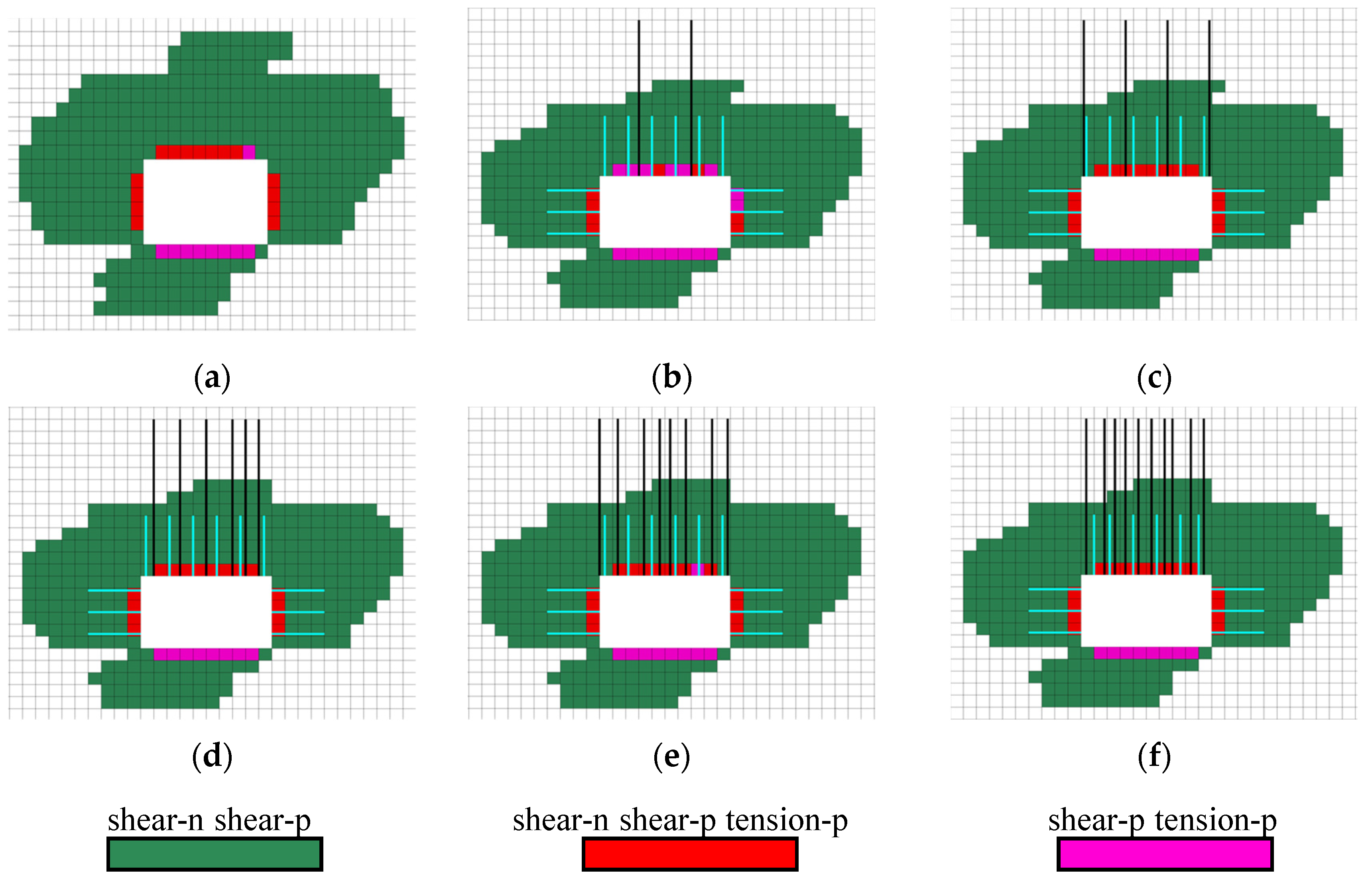
3.2. Control Analysis of Support Resistance on Surrounding Rock Plastic Zone

Taking the stress state of surrounding rock nearly 3 m in front of the working face of the Lijiahao 31115 ventilation roadway (see Section 2.5) as an example, the cable structure element in Flac 3D numerical simulation software is used to simulate the bolt (cable) and analyze the control effect of the bolt (cable) on the plastic zone of the roadway roof. The scheme is shown in Table 4. The anchor bolt (cable) parameters are assigned according to the actual values on site. The anchor bolt (cable) has an anchorage length of 1 m (2 m) and a prestress of 120 kN (300 kN), which are arranged perpendicular to the roadway roof. There are three bolts for each roadway side. The shape and extent of the surrounding rock plastic zone under different support schemes are shown in Figure 12. It can be seen that with the increase in the number of anchor cables, the shape and extent of the surrounding rock plastic zone of the roadway have hardly changed significantly. In order to quantitatively analyze the control effect of the support resistance on the plastic zone, the relationship between the support resistance and the plastic zone volume of the surrounding rock is calculated, as shown in Figure 13. When there is no support, the plastic zone volume of surrounding rock is about 88.1 m3. When the number of anchor cables increases from two to four sets, that is, the support resistance increases from 0.26 MPa to 0.38 MPa, the plastic zone volume decreases from 88.1 m3 to about 80 m3. If the support resistance continues to increase, the plastic zone volume of surrounding rock hardly changes. The volume control rate of support to the surrounding rock plastic zone is about 9%. The above analysis shows that bolt (cable) support has a limited effect on controlling the plastic zone of surrounding rock, and the existing bolt (cable) support technology cannot effectively reduce the plastic zone.

3.3. Advance Support Principle of Mining Face

Under economic conditions, the support resistance provided by the existing support technology has very limited control over the plastic zone, so the support design should mainly adapt to the surrounding rock deformation and prevent roof falls. The elongation of commonly used bolts (cables) in coal mines is 17% (3.5%), that is, the maximum deformation of a 2 m bolt is about 300 mm, and the maximum deformation of a 6.5 m anchor cable is about 220 mm. For the surrounding rock of the roadway roof at ASSoMF, the bolt often fails because the length is not big enough to be anchored in the stable rock stratum. Although the anchor cable can be anchored in the stable rock stratum, its low elongation cannot adapt to the large deformation of the surrounding rock. The active support such as a bolt (cable) may find it difficult to adapt to the large deformation of roadway-surrounding rock due to its material property limitations. Therefore, for the advance support of a large deformation roadway, passive support technology should be considered in order to give full function to the ability of passive support to adapt to the large deformation of the roadway. In addition, the soft roof is repeatedly supported by advance hydraulic support, which may collapse easily. Compared with the larger labor intensity of single pillar, the mechanized movement of support equipment also needs to be considered. The key purpose of passive support shall be to ensure that the support body has sufficient strength and stiffness, can bear the load of broken roof, and avoids repeated support to the roof.

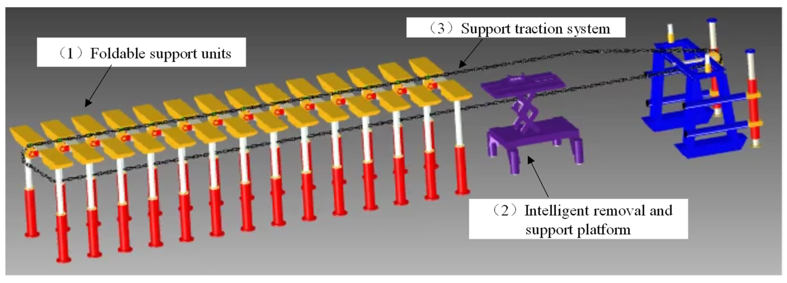
4. Advance Support Equipment without Repeated Support for Mechanized Movement

4.1. Characteristics of the Equipment

Based on the above research, this paper proposes advance support equipment without repeated support for mechanized movement, as shown in Figure 14. The equipment is mainly composed of three parts: (1) foldable support units; (2) an intelligent removal and support platform; and (3) a support traction system. The equipment can mechanically fold support units at the rear through the intelligent operation platform, and then transfer it to the front through the traction system for re-erection so that the support units can avoid repeatedly supporting the roadway roof.
The top beam of the support unit can be folded horizontally, which is conducive to movement automation; The beam can be retracted, which is more applicable to the roadway with serious deformation on both sides. The beam is a double-plane independent support structure which can adapt to various changes in coal seam dip and is more suitable for a broken roof with asymmetric deformation, as shown in Figure 15.
The main technical parameters of the advance support equipment are shown in Table 5. The height of the support is 2500–4200 mm, which means that the support can adapt to the deformation of a roadway roof of about 1700 mm, which is far greater than the extension of the bolt (cable) support, indicating that the equipment can adapt to the large deformation characteristics of the roadway roof.

4.2. Analysis of Support Opportunity

Assuming that the support is fully coupled with the surrounding rock roof of the roadway, the coupling model of the surrounding rock may be established and and supported using flac3d software [33], as shown in Figure 16. The stress of support top beam under different roof subsidence is shown in Table 6. It can be seen that with the increase in the roof subsidence before the support (from 0 to 45 mm), the pressure on the support top beam decreases first, and then increases after the support is balanced (2.5~0.3~0.4 MPa); therefore, there is an optimal support opportunity. When the roof subsidence before the support is 35 mm, the load on the support top beam is the smallest, at about 0.3 MPa.

4.3. Stability Analysis the Equipment

According to the above analysis, the maximum load on the top beam of the support is about 2.5 MPa. The overall material of the support is Q235 steel (elastic modulus: 210 GPa, Poisson’s ratio: 0.28), that is, the yield strength is 235 MPa. In order to check the strength of the support, the support model is established, and some details that do not affect the results are simply processed.
A total of 1.5 times the maximum load (3.75 MPa) is used to load the top beam of the support. The overall stress diagram of the support is shown in Figure 17. It can be seen from the figure that the stress on the top beam of the support is about 43 MPa, and the stress on the support column is the maximum, about 229 MPa. The stress on the support is within the range of material strength, indicating that the support can well bear the load of the roof and maintain the stability of the roadway roof.

5. Conclusions

(1) Due to the influence of mining, the roadway at ASSoMF is in a non-uniform stress field; the maximum confining pressure ratio can reach 7, and the direction of the maximum principal stress also deflects (the angle with vertical direction is about 10–25°). This makes the roof of the roadway produce butterfly asymmetric damage, and the roadway along the goaf side is more damaged than the roadway along the solid coal side.
(2) The support resistance provided by the existing support technology is much smaller than the original rock stress, and the control rate of the plastic zone is only about 9%, which is characterized by “low resistance and small effect”. The advance support should mainly adapt to the surrounding rock deformation of the roadway. Passive support has large adaptability to surrounding rock deformation, and it should be ensured that it has sufficient strength to bear the load of the broken roof.
(3) The advance support equipment without repeated support for mechanized movement is proposed. The strength check results of the support show that the load borne by the support is within the range of material strength. There are inevitable errors between the theoretical analysis and the actual engineering conditions, so this support equipment only provides a reference for roadway support under similar geological and geotechnical circumstances.

Author Contributions

Conceptualization, J.L. and C.L.; methodology, J.L. and C.L.; software, J.L. and W.Z.; writing—original draft preparation, J.L.; writing—review and editing, J.R.; visualization, J.L. and F.T. All authors have read and agreed to the published version of the manuscript.

Funding

This work was partially supported by the National Natural Science Foundation of China (Grant No. U22A20165) and the Fundamental Research Funds for the Central Universities (2022YJSNY10).

Data Availability Statement

The manuscript data used to support the findings of this study are available from the corresponding author upon request.

Conflicts of Interest

The authors declare no conflict of interest.

References

  1. Esterhuizen, G.S.; Gearhart, D.F.; Klemetti, T.; Dougherty, H.; Van Dyke, M. Analysis of gateroad stability at two longwall mines based on field monitoring results and numerical model analysis. Int. J. Min. Sci. Technol. 2019, 29, 37–45. [Google Scholar] [CrossRef]
  2. Xu, Y.J.; Zhang, K.; Li, D.Y.; Zhang, D.S. Theory and application of self-adaptive support for advanced powered support. J. China Coal Soc. 2020, 45, 3615–3624. [Google Scholar] [CrossRef]
  3. Cai, M.F. Key theories and technonogies for surrounding rock stability and ground control in deep mining. J. Min. Strat. Control. Eng. 2020, 2, 5–13. [Google Scholar] [CrossRef]
  4. Esterhuizen, G.S.; Tulu, I.B.; Gearhart, D.F.; Dougherty, H.; Van Dyke, M. Assessing support alternatives for longwall gateroads subject to changing stress. Int. J. Min. Sci. Technol. 2020, 31, 103–110. [Google Scholar] [CrossRef]
  5. Zhu, J.F.; Yin, Q.; Zhang, J.M.; Jing, H.W. Deformation evolution and asymmetric support of deep-buried surrounding rock mass with a gently inclined weak interlayer. J. Min. Strat. Control. Eng. 2022, 4, 47–61. [Google Scholar] [CrossRef]
  6. Liu, H.S.; Luan, H.J.; Qiao, J.L.; Li, G.F.; Zhang, S.H. Failure mechanism and strengthening support technology of gangue-containing coal roadway sidewall. J. Min. Strat. Control. Eng. 2022, 4, 38–49. [Google Scholar] [CrossRef]
  7. Sasaoka, T.; Mao, P.; Shimada, H.; Hamanaka, A.; Oya, J. Numerical analysis of longwall gate-entry stability under weak geological condition: A case study of an indonesian coal mine. Energies 2020, 13, 4710. [Google Scholar] [CrossRef]
  8. Duan, C.R.; Zheng, Q.; Xue, J.H.; Yu, G.F.; Luo, Y. Experimental study on zonal failure discontinuous deformation of deep surrounding rock under different working conditions. J. Min. Strat. Control. Eng. 2021, 3, 76–84. [Google Scholar] [CrossRef]
  9. Kong, H.P. Spatial scale analysis on coal mining and strata control technologies. J. Min. Strat. Control. Eng. 2020, 2, 5–30. [Google Scholar] [CrossRef]
  10. Mao, P.; Shimada, H.; Hamanaka, A.; Wahyudi, S.; Oya, J.; Naung, N. Three-dimensional analysis of gate-entry stability in multiple seams longwall coal mine under weak rock conditions. Earth Sci. Res. J. 2020, 9, 1. [Google Scholar] [CrossRef] [Green Version]
  11. Guo, J.S. Selection design and outlook on advanced hydraulic powered support of gateway in fully-mechanized coal mining face. Coal Sci. Tech. 2016, 44, 30–35. [Google Scholar] [CrossRef]
  12. Zhang, N.; Han, C.L.; Xie, Z.Z. Theory of continuous beam control and high efficiency supporting technologyin coal roadway. J. Min. Strat. Control. Eng. 2019, 1, 48–55. [Google Scholar] [CrossRef]
  13. Li, J.; Lian, X.Y.; Li, C.; Wu, Z.; Wang, J. Failure mechanism and support system of roofs in advance areas affected by mining under the condition of soft rock stratum. Front. Earth Sci. 2022, 10, 1–15. [Google Scholar] [CrossRef]
  14. Kang, H.P.; Jiang, P.F.; Wu, Y.Z.; Gao, F.Q. A combined “ground support-rock modification-destressing” strategy for 1000-m deep roadways in extreme squeezing ground condition. Int. J. Rock Mech. Min. 2021, 142, 1–12. [Google Scholar] [CrossRef]
  15. Pan, Y.S.; Gao, X.P.; Wang, W.; Xiao, Y.H. Research of hydraulic powered supports for entries’ advanced support in fully mechanized working face of rock burst mine. Coal Sci. Tech. 2021, 49, 1–12. [Google Scholar] [CrossRef]
  16. Jiang, L.; Kong, P.; Shu, J.; Fan, K. Numerical analysis of support designs based on a case study of a longwall entry. Rock Mech. Rock. Eng. 2019, 52, 3373–3384. [Google Scholar] [CrossRef]
  17. Pan, Y.S.; Xiao, Y.H.; Li, G.Z. Roadway hydraulic support for rockburst prevention in coal mine and its application. J. China Coal Soc. 2020, 45, 90–99. [Google Scholar] [CrossRef]
  18. Guo, N. Research on Advance Stress Distribution Law of Thick Hard Roof and Optimization of Advance Support Technology. Master’s Thesis, China University of Mining and Technology, Xuzhou, China, 2021. [Google Scholar] [CrossRef]
  19. Cai, L. The Coupling Mechanism and Application of Advanced Support-Anchorage Surrounding Rock in Fully Mechanized Coal Face. Master’s Thesis, China University of Mining and Technology, Xuzhou, China, 2018. [Google Scholar]
  20. Yao, Q.L.; Wang, H.H.; Xia, Z.; Li, L.H.; Zhu, L.; Li, X.H. Key technology and application of active fore poling for longwall coal mining in coal mine. J. Min. Safety Eng. 2020, 37, 289–297. [Google Scholar] [CrossRef]
  21. Yao, Q.L.; Li, Y.H.; Xia, Z.; Li, X.H.; Wang, H.H.; Chao, N. Theory and application of roof superimposed beam support of coal roadway based on effective anchorage layer thickness. J. China Coal Soc. 2022, 47, 672–682. [Google Scholar] [CrossRef]
  22. Zhou, L. Application Study of Active Advanced Support in Longwall Mining. Master’s Thesis, China University of Mining and Technology, Xuzhou, China, 2021. [Google Scholar] [CrossRef]
  23. Zhao, S.R. Study on Non-Isometric Support Characteristics of Advanced Hydraulic Support Bracket Partition. Master’s Thesis, Liaoning Technical University, Fuxing, China, 2021. [Google Scholar] [CrossRef]
  24. Lai, H.C. Research on Supporting Features and Strength of Fully Mechanized Face Advanced Hydraulic Support. Master’s Thesis, Liaoning Technical University, Fuxing, China, 2019. [Google Scholar] [CrossRef]
  25. Ma, M.; Guo, Q.; Pan, J.; Ma, C.; Cai, M. Optimal support solution for a soft rock roadway based on the drucker–prager yield criteria. Minerals 2022, 12, 1. [Google Scholar] [CrossRef]
  26. Wang, F.; Wu, C.; Yao, Q.; Li, X.; Chen, S.; Li, Y.; Li, H.; Zhu, G. Instability mechanism and control method of surrounding rock of water-rich roadway roof. Minerals 2022, 12, 1587. [Google Scholar] [CrossRef]
  27. Zhang, K.; Li, Y.X.; Zhong, D.H.; Meng, X.J.; Huang, Q.X.; Xu, Y.J.; Chen, H.Y.; Ma, Y.; Zhang, D.S.; Huang, L.S.; et al. Research and experimental verification of mechanical characteristics of advanced hydraulic support group-anchor coupling support. Chin. J. Rock Mech. Eng. 2021, 40, 1428–1443. [Google Scholar] [CrossRef]
  28. Xu, Y.J.; Zhang, D.S.; Li, D.Y. Study on advanced powered support with omni-directional walking function. Coal Sci. Tech. 2019, 47, 161–166. [Google Scholar] [CrossRef]
  29. Wang, Q.; Wang, B.K.; Zheng, Y. Research and application of alternate circulation advance support technology for mining entry. J. Min. Safety Eng. 2022, 39, 750–760. [Google Scholar] [CrossRef]
  30. Itasca Consulting Group Inc. Itasca’s FLAC3D Documentation; Itasca Consulting Group Inc.: Minneapolis, MN, USA, 2022. [Google Scholar]
  31. Guo, X.F.; Zhao, Z.Q.; Gao, X.; Wu, X.Y.; Ma, N.J. Analytical solutions for characteristic radii of circular roadway surrounding rock plastic zone and their application. Int. J. Min. Sci. Technol. 2019, 29, 263–272. [Google Scholar] [CrossRef]
  32. Li, C.; Wu, Z.; Zhang, W.L.; Sun, Y.H.; Zhu, C.; Zhang, X.H. A case study on asymmetric deformation mechanism of the reserved roadway under mining influences and its control techniques. Geomech. Eng. 2020, 22, 449–460. [Google Scholar] [CrossRef]
  33. Xue, G.H.; Guan, J.; Cheng, J.J.; Zhang, H.; Ji, W.L.; Jing, X.P.; Wu, M. Design of advance support for deep fully-mechanized heading roadway and its support performance analysis. Coal Sci. Tech. 2018, 46, 15–20. [Google Scholar] [CrossRef]
Figure 1. Geological drilling column.
Minerals 13 00178 g001
Figure 2. Layout of the working face.
Minerals 13 00178 g002
Figure 3. Numerical simulation model.
Minerals 13 00178 g003
Figure 4. Distribution characteristics of stress on the side of goaf.
Minerals 13 00178 g004
Figure 5. Variation of the angle between the maximum principal stress and the vertical direction (the vertical direction is the origin, and the counterclockwise direction is positive).
Minerals 13 00178 g005
Figure 6. Characteristics of axial stress distribution of gob-side roadway.
Minerals 13 00178 g006
Figure 7. Characteristics of axial stress distribution of solid coal roadway.
Minerals 13 00178 g007
Figure 8. Distribution characteristics of surrounding rock plastic zones at different locations at the gob-side roadway (affected by side mining): (a) 200 m behind the previous working face; (b) 700 m behind the previous working face. The gray dotted line represents the center line of the roadway.
Minerals 13 00178 g008
Figure 9. Distribution of surrounding rock plastic zone at different positions in front of the gob-side roadway. (a) 1 m; (b) 2 m; (c) 3 m; (d) 4 m; (e) 10 m; (f) 20 m. The gray dotted line represents the center line of the roadway.
Minerals 13 00178 g009
Figure 10. Distribution of surrounding rock plastic zone at different positions in front of the solid coal roadway. (a) 1 m; (b) 2 m; (c) 3 m; (d) 5 m; (e) 10 m; (f) 20 m. The gray dotted line represents the center line of the roadway.
Minerals 13 00178 g010
Figure 12. Shape and scope of the surrounding rock plastic zone of each support scheme. (a) group 1; (b) group 2; (c) group 3; (d) group 4; (e) group 5; (f) group 6. Blue line: bolts; black line: cables.
Minerals 13 00178 g012
Figure 13. Control effect of support resistance on plastic zone.
Minerals 13 00178 g013
Figure 14. Advance support equipment without repeated support for mechanized movement.
Minerals 13 00178 g014
Figure 15. Structure of support unit.
Minerals 13 00178 g015
Figure 16. Coupling model of surrounding rock and support.
Minerals 13 00178 g016
Figure 17. Stress diagram of the support.
Minerals 13 00178 g017
Table 1. Parameters of double-yield model in goaf.
Density
(kg/m3)
Bulk Modulus
×103 (MPa)
Shear Modulus
×103 (MPa)
Friction Angle (°)Dilation Angle (°)
17505.54.6207
Table 2. Lithology and rock physical and mechanical parameters.
LithologyDensity
(kg/m3)
Bulk Modulus ×103 (MPa)Shear Modulus
×103 (MPa)
Friction
Angle (°)
Cohesion
(MPa)
Tensile Strength (MPa)
Sandy mudstone 222002.71.6291.21.06
Fine-grained sandstone26004.52.8315.62.1
Silt stone 224003.22.6271.41.3
Coal13502.51.2280.90.6
Silt stone 124003.62.6321.61.3
Sandy mudstone 124003.81.8281.61.2
Table 3. Advance support technology for some coal mining in Shendong mining area.
Mine NameWorking FaceMining HeightBurial DepthAdvance Support Technology
Ulan Mulun124052.5~3 m140 mHR: reinforcement cable; VR: advance hydraulic support
Ulan Mulun314113.8 m170 mSingle-prop support
Liuta221023 m110 mHR: single-prop support; VR: advance hydraulic support
Shigetai222011.9 m80 mHR: reinforcement cable; VR: single-prop support
313073.6100 mHR: reinforcement cable; VR: advance hydraulic support
Cuncaota No. 2 Mine312053.6 m310 mHR: single-prop support; VR: advance hydraulic support
Halagou225214.6 m60 mAdvance hydraulic support
Shangwan221046.5 m120 mAdvance hydraulic support
Bulianta224086.5 m250 mHR: reinforcement cable; VR: advance hydraulic support
Daliuta525026.8 m170 mAdvance hydraulic support
Yujialiang522094.2 m100 mSingle-prop support
Baode81308Ming 3.8 m
Caving 2.8 m
350 mHR: advance hydraulic support; VR: portal support
Buertai222043.9 m280Single-prop support
42106Ming 3.6 m
Caving 3 m
350HR: single-prop support; VR: advance hydraulic support
42204Ming 3.7 m
Caving 2.5 m
400 mHR: reinforcement cable; VR: advance hydraulic support
HR: haulage roadway or solid coal roadway; VR: ventilation roadway or gob-side roadway. Data resource: operating procedures for coal mines in the Shendong mining area.
Table 4. Support scheme.
Support Scheme GroupNumber of Bolts/PieceDensity of Anchor Cable/
(Piece m−1)
Support Resistance/MPa
1620.26
2640.38
3660.50
4680.62
56100.74
Table 5. Main technical parameters.
CategoryParameter
Passage width≥3000 mm
Passage height≥2500 mm
Working height2500~4200 mm
Working resistance>5000 KN
Support strength>0.7 MPa
Table 6. Load on support under different roof subsidence.
Subsidence of Roof before
Support/mm
Load on Support Top Beam after
Support Balance/MPa
02.50
100.50
150.45
200.43
250.41
300.37
350.30
400.35
450.40
Disclaimer/Publisher’s Note: The statements, opinions and data contained in all publications are solely those of the individual author(s) and contributor(s) and not of MDPI and/or the editor(s). MDPI and/or the editor(s) disclaim responsibility for any injury to people or property resulting from any ideas, methods, instructions or products referred to in the content.

