1. Introduction
Deep mineral exploration relies on cost-effective geophysical methods to obtain the distribution and geometry of ore bodies or ore-bearing structures at the deposit scale [
1,
2,
3,
4]. Electromagnetic (EM) methods are tools that have proven to be particularly useful for characterizing the subsurface with electrical conductivity (or its reciprocal, resistivity), as the mineralization is often associated with anomalies in the conductivity property [
5,
6,
7,
8]. Time-domain electromagnetic (or transient electromagnetic, TEM) is one of the most commonly used EM methods for minerals due to its high efficiency and high signal–noise ratio compared to other EM methods [
9,
10,
11,
12].
A typical TEM survey turns off the transmitter current in a closed wire loop or in a grounded wire line laid on the surface; the abrupt change of current in the wire induces secondary currents in the subsurface, and such secondary fields decay with time; receivers on the surface measure the EM fields as a function of time; qualitative and quantitative analysis of the decay pattern of EM fields provide information about conductivity distribution—a slower decay may indicate the presence of high-conductivity ore bodies or geological objects, and the early and late-time measurements correspond to shallow and deep structures, respectively. In mineral exploration, every conceivable configuration of transmitter and receiver has been tried for TEM to achieve the optimal coupling with the target. There are two configurations that are more frequently used in practice. The first is the central loop configuration, which utilizes a small transmitter loop and a receiver coil in the center (or close proximity) of the loop; both the transmitter and receiver move together and take measurements at a series of locations [
13]. Such a configuration can illuminate a geological target from multiple locations, yielding datasets with high spatial resolution. However, a small transmitter loop may not carry a sufficient source excitation moment (the product of loop area and current) for deep penetration, and rough topography or thick vegetation can significantly restrict the deployment and movement of the system. As a result, a large and fixed loop configuration has been developed so there would be only one (or a few) stationary transmitter loop(s), yet multiple receivers could measure in or around the loop(s) [
14,
15].
The interpretation method of such large and fixed loop TEM data has evolved. Conventionally, data are only acquired in the central region of the loop, where the primary magnetic field at the exploration depth is supposed to be purely vertical; thus, under the assumption of 1D layered earth, the induced current is purely horizontal and the secondary magnetic field is the strongest in the vertical component on the surface. This assumption significantly simplifies the data interpretation, since the concept of apparent conductivity is well-defined and the time channels can be straightforwardly transformed to the depths [
16,
17]. However, significant lateral variation in geology, as one often encounters in mineral exploration, can violate the assumption and complicate the interpretation. In addition, when the receivers are outside of the source loop, TEM data may have negative responses in the decay curves because of the non-trivial geometric coupling; as a result, the decay rate of the transient signals after source turn-off is no longer indicative of the subsurface conductivity [
18]. A common practice in the mining industry is to utilize plate modeling (or other simple geometric objects) to roughly reproduce the TEM responses in 3D [
19]. This approach is effective in capturing the position, orientation, and geometry of compact ore bodies that are regularly shaped, but cannot properly handle complex objects or multiple objects simultaneously.
Rigorous 3D modeling and inversion that discretize the subsurface space into many small voxels have been developed to simulate arbitrarily complex geology [
20,
21,
22,
23]. The theories for quantitatively interpreting TEM data have been well established, as previous publications in the last decades have proposed a number of numerical approaches to solve both the forward and inverse problems [
24,
25,
26,
27]. Despite the advancements in theoretical studies, unfortunately, 3D modeling and inversion are still mostly absent in industrial production. One of the most obvious reasons is that the computational cost, particularly the time required by running the modeling programs, is often prohibitively high [
28,
29,
30]. 3D inversion is also subject to severer non-uniqueness and convergence problems as a result of the drastically increased number of unknowns compared to 1D or 2D [
31]. Such problems become much more challenging for the large-loop TEM, in which the subsurface is only illuminated in a fixed way [
32]; the negative transient data (sign reversal) because of the out-loop receivers and increased likelihood of complex source–target–receiver coupling relations add the difficulty of fitting zeros-crossing data, which, according to our experiences, requires careful tuning of the initial model and data noise floor to ensure the convergence of inversion. The time cost, stability issue, and few successful know-how cases are all responsible for the slow adoption of 3D-voxel modeling and inversion by the mining industry.
In the present work, we aim to advocate for the application of 3D forward and inverse modeling technology to the practice of mineral exploration by documenting an inspiring case study of large-loop TEM. In particular, we overcome the difficulties in the computing time with a novel parallel solving algorithm called “survey decomposition” [
18]. Then, the accelerated 3D modeling facilitates our investigation into the phenomenon of negative transient TEM data, which are deemed to be the cause of instability in the 3D-voxel inversion, and helps us find a more numerically stable initial conductivity model for the inversion. In the end, we demonstrate how a fine-tuned 3D TEM inversion reveals the mineralizing geology characterized by high lateral inhomogeneity that conventional TEM data interpretation methods cannot properly image.
2. Geological Setting
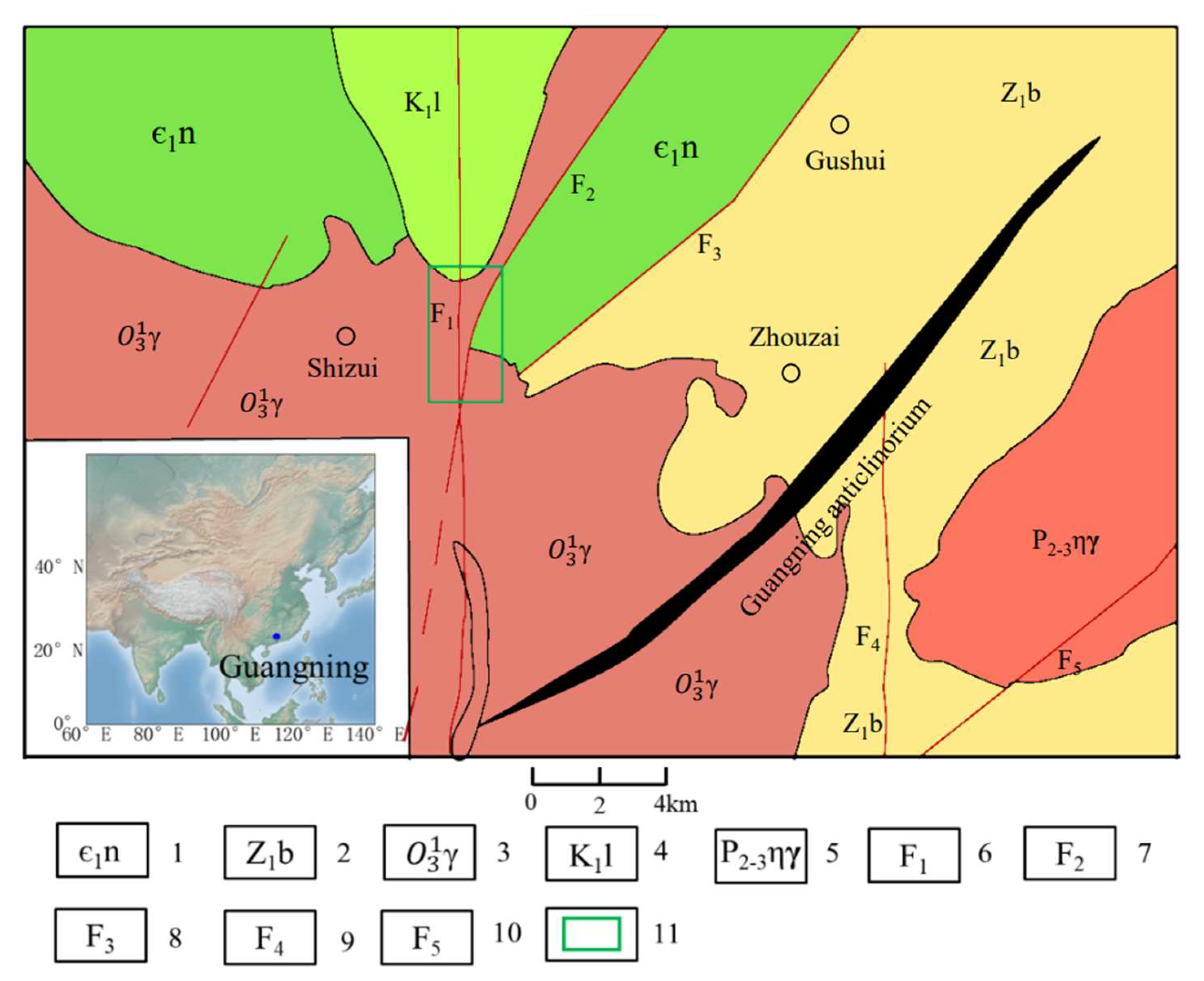
The Shizui polymetallic mining district in Guangning, Guangdong is situated at the southeastern edge of the Guangdong–Guilin Uplift, northwest of the Wuchuan–Sihui Fault Zone, and north of the Guangning Anticlinorium. The area is composed of siliceous rocks, quartz sandstones, and Cambrian black shales, while being intruded by granite at both ends. Two major fault zones have been discovered in the district: the Luoding–Guangning Fault Zone, with strong lithification and silicification, as well as gold and rare earth ore deposits; and the Wuchuan–Sihui Fault Zone, consisting of several north–east-oriented granitic mylonite (
Figure 1).
The north–east-oriented Muge Fault, Gushui Fault, and north–south-oriented Chenhuai Fault manifest the tectonic history in the survey area as the primary faults, while the faults in north–east, north–northeast, northwest, and northeast–east directions are the secondary faults of higher maturity. Faults are the main ore-bearing structures in the region, among which the northeast and north–northeast (nearly north–south) oriented faults are the primary hosts of the polymetallic ores. The north–east oriented faults are composed of silicified rocks, silicified faulted rocks, phyllite, and a small number of broken quartz dikes and carbonaceous breccias. The vital mineral alteration process includes limonitization, and secondly, silicification, pyritization, and chalcopyritization, which all contribute to the formation of the gold deposits in the mining area. The northeast–east (nearly east–west) faults developed in the silicified rock belt and deposited gold and tungsten.
Extensively exposed in the area, the Cambrian Gaotan Formation is made of fine-grained quartz sandstone interbedded with siltstone and slate, and a layer of thick laminated grayish-white sandy quartz sandstone at the bottom. At the bottom lamination’s center is a ‘silica cap’ of low conductivity being developed. The Cambrian Niujiaohe Formation is mostly exposed on the northwestern side, composed of siltstone and metamorphic sandstone with a black slate of high conductivity at the bottom. Rock samples were collected from the area for the measurement of electrical properties. The Gaotan Formation generally has high resistivities, ranging from 8000 Ω·m to 20,000 Ω·m, with an average of about 13,000 Ω·m (8 pieces of Ordovician granites). The Niujiaohe Formation’s conductivity ranges from 46 Ω·m to 200 Ω·m, with an average of about 100 Ω·m (16 sandstones and charcoal-bearing slates).
3. Field Data Acquisition
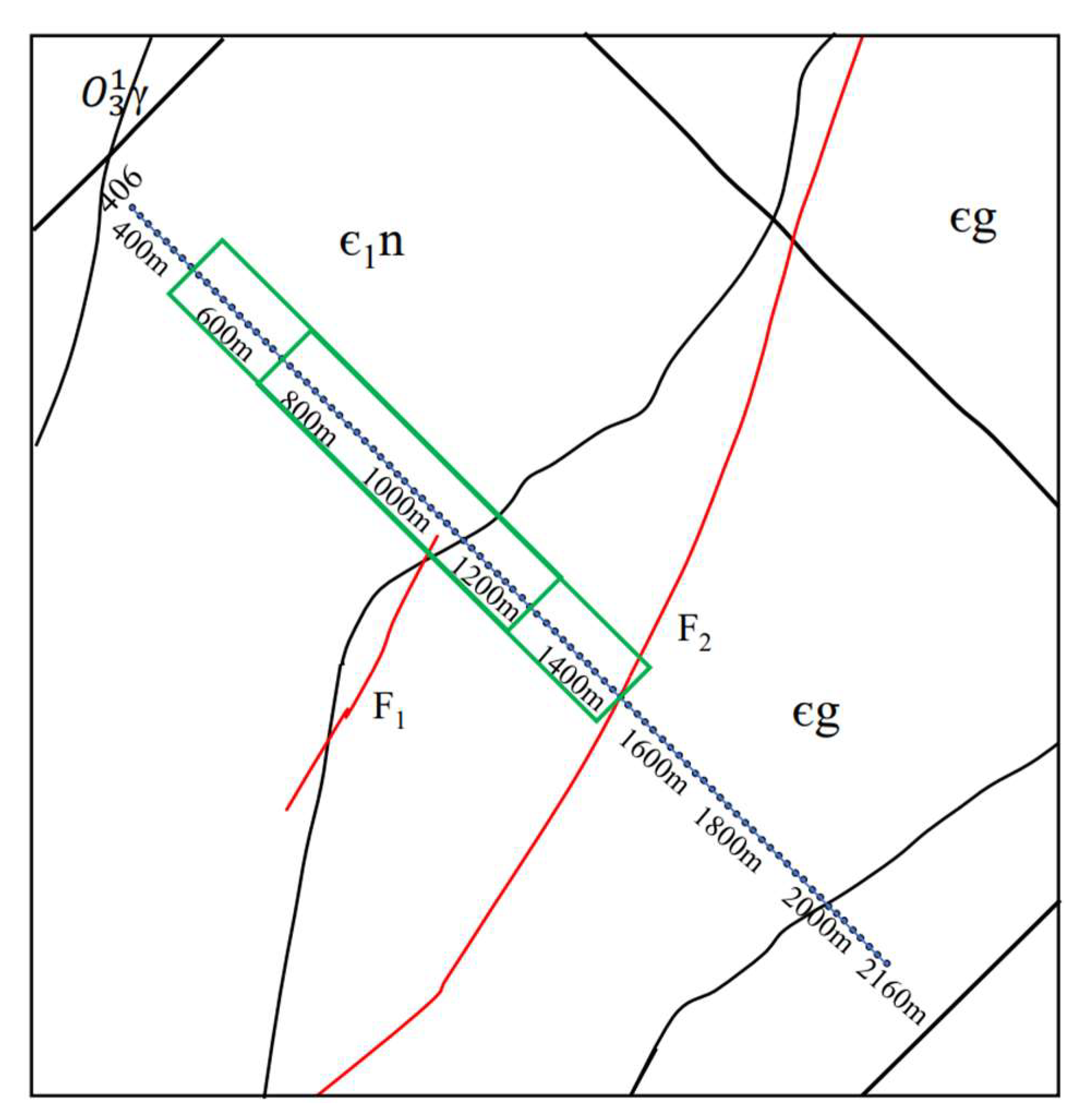
The TEM survey, carried out by the Guangdong Provincial Geophysical Prospecting in 2019, consists of multiple NW–SE parallel lines across the major regional faults and the boundary between the Niujiaohe and Gaotan Formations. The detection area is located in a mountainous area with complex terrain, the available space on both sides of the measurement line is limited, and the field crew implemented a TEM configuration that combines the large fixed loop and moving central loop. The new configuration deploys a rectangular loop (750 m × 150 m) elongated and arranged along the line direction; multiple vertical coil receivers separated by 10 m are placed in the central region of the source loop to measure the time derivative of the vertical magnetic field (dBz/dt) as TEM data; once the measurements are finished at those receiver positions, the rectangular loop moves to the next section until the entire line of 1820 m runs out (
Figure 2). The main reason for having so many receiving points within the transmitting coil is to increase the lateral resolution, provide spatial coverage along the survey line, and avoid errors in the acquisition of observations at some measurement points. The measurement points are at the central region of the loop, where the vertical component of the primary field is mostly constant. Thus, the loop is so long that data are not significantly affected by being close to the wire of the loop.
The instrument used in the survey was a GDP-32II system manufactured by Zonge International in Arizona. The source loop carries a 6-A current in a ramp-off waveform with a ramp length of 0.12 ms. The receiver coil has an effective area of 10
4 m
2, and measures dBz/dt data at 28 time channels from 0.05262 to 24.291 ms. In this paper, we focus on Line 406, for which, six large rectangular loops were consecutively deployed to cover the range from Station 340 to 2160 (in meter). The green long rectangles in
Figure 2 show the second and the third transmitter loops used in the survey. Some stations are repeatedly measured for different source loops to ensure continuity. The raw data are normalized by the receiver’s effective area and current for plotting and analysis.
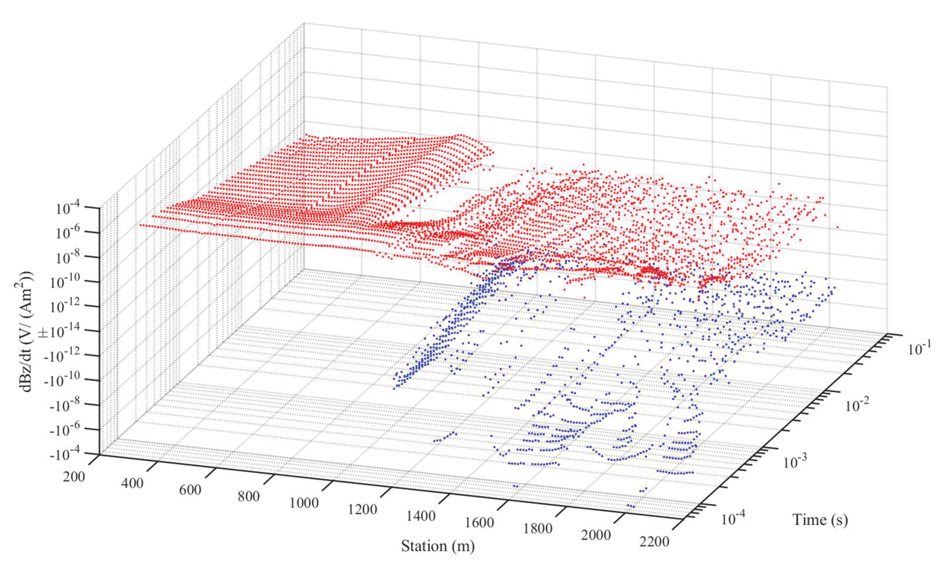
The acquired TEM data along Line 406 are characterized by two distinct patterns of decay curve (
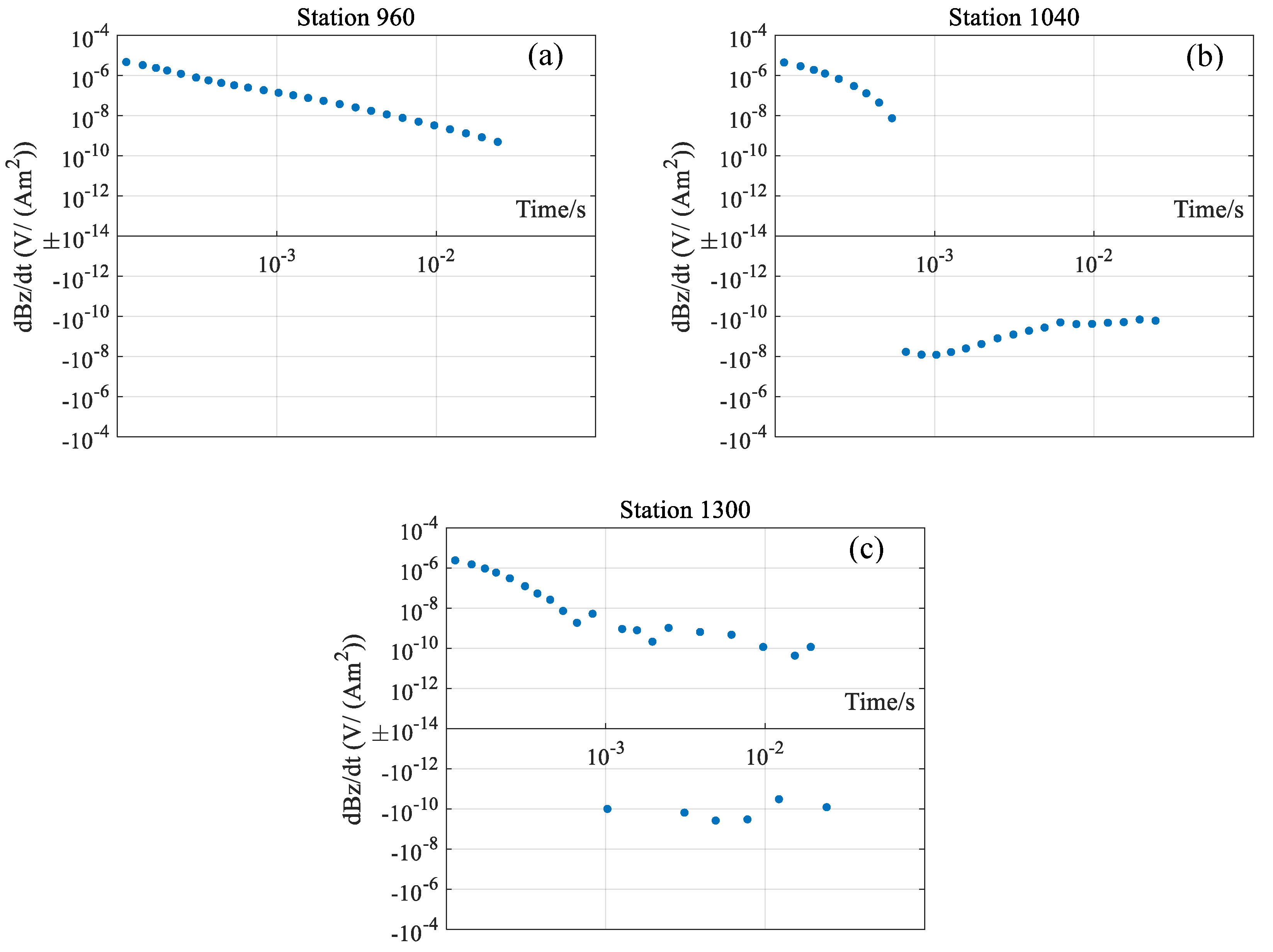
Figure 3). The TEM data at receivers from the beginning of the line to Station 980 on the side of Niujiaohe Formation behave normally with a smooth and relatively slow decay all above the noise level, indicating a more conductive subsurface (
Figure 4a). In contrast, the data from Station 990 to the end of the line on the side of the Gaotan Formation contains a large number of negative transient data and is approximately 7% below the noise level. The negative data generally appear as two types. The first type has a rapid decay to weak signals below the noise level of about 10
−10 V/(Am
2) at the late time channels (
Figure 4c); the second type, as is the most evident near Station 1000, exhibits a transient from positive to negative with reasonably strong signal strengths (
Figure 4b). The study area is in a mountainous area with minimum cultural noise and interference from infrastructures. Repeated measurements have confirmed that the negative transient data of the second type are not caused by instrument malfunctioning or environmental noise, and should have geological significance. The variation of decay rate from slow to fast, as observed in the data plot, is consistent with the change of rock type from the more conductive Niujiaohe Formation to the more resistive Gaotan Formation. Next, we quantitatively interpret the data using rigorous 3D forward modeling and inversion, with an emphasis on the transition zone near Station 1000, where the negative transients are the most prominent.
5. 3D Forward Modeling Analysis
Many studies have shown that central-loop TEM data over a 1D layered conductivity model must not show negative transients or sign reversals, unless a strong induced polarization (IP) effect is present [
36]. In the field data presented in (Marchant et al., 2014) [
37], the central-loop TEM data with the IP effect have two features. First, the data along the survey line may show a symmetrical distribution when crossing the chargeable object. Second, the TEM data above the chargeable object have higher values at early times and lower (even negative) values at late times, sometimes referred to as “shape reversal”. The field data in this paper does not look similar to any of the known IP features. While admitting that mineralization can often be associated with the IP effect, we consider the non-1D effect to be mostly responsible for the negative transients, because of the strong lateral inhomogeneity evidenced by the geological mapping, rock sample resistivity data and the abrupt change in TEM decay patterns. Fast 3D TEM modeling using survey decomposition effectively reduces the computing time to seconds or minutes, so exploration geophysicists can carry out quick modeling tests on such hypophysis, even during the survey operation if connected to the computational resources. In the following, we demonstrate how we advance our understanding about the unusual decays in the TEM data of Shizui with synthetic conceptual models and 3D forward modeling exercises, and how forward analysis can be critical to successful inverse modeling.
5.1. The Infinite Vertical Contact Model
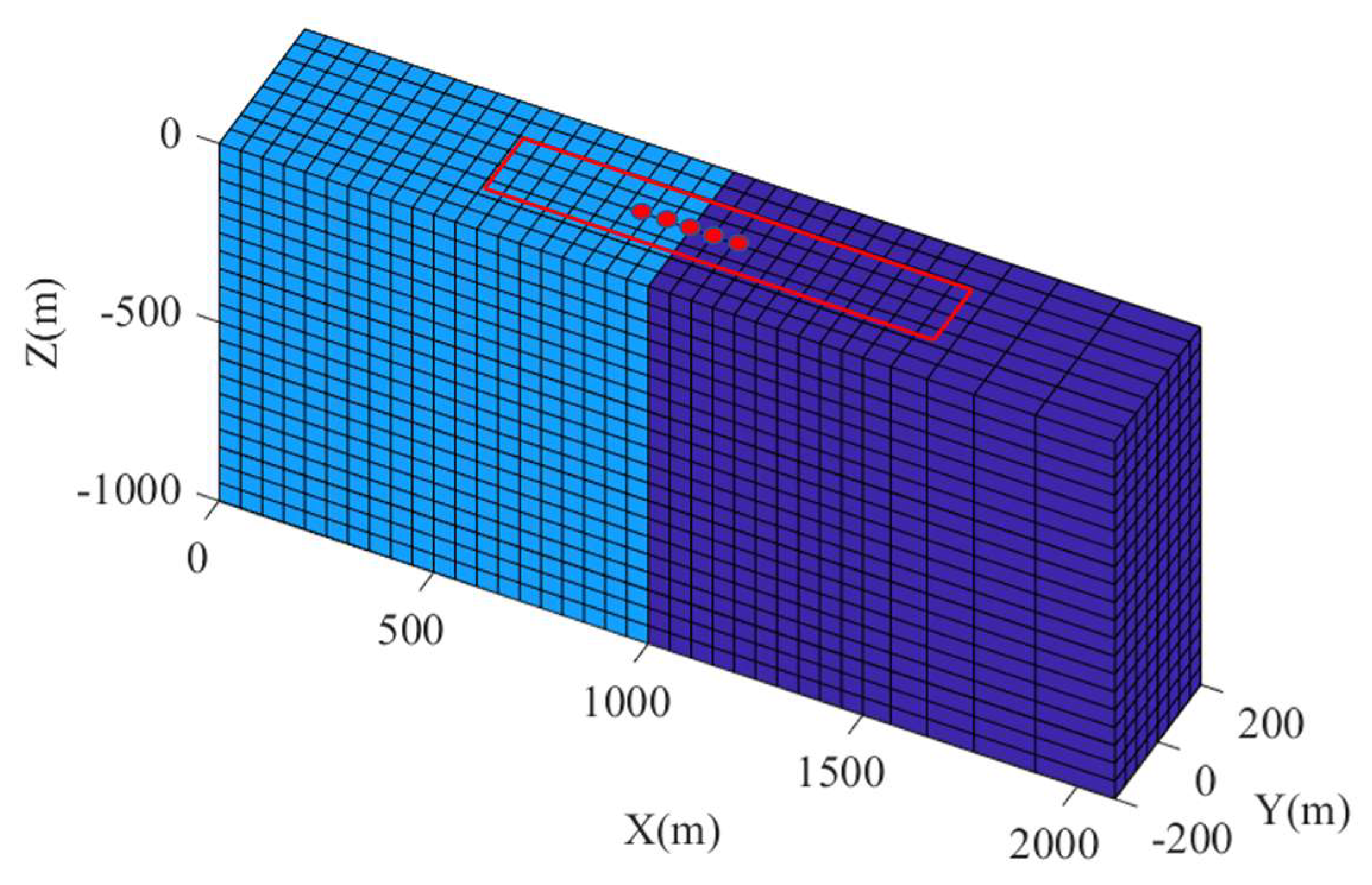
The decay pattern of TEM data changes abruptly at about Station 1000. Thus, as our best initial guess, the first group of synthetic models consists of two quarter-spaces, one conductive and the other resistive, that together make a half-space representing the subsurface, and the geological contact of the quarter-spaces is located at X = 1000 m (
Figure 6). We fix the conductivity of the resistive terrane (Gaotan Formation) to be 10
−4 S/m and alter the conductive terrane (Niujiaohe Formation) to be 10
−2, 10
−1, 10
0, and 10
1 S/m as Models 1, 2, 3, and 4, respectively.
A rectangular source loop of 750 m × 150 m is laid across the geological contact (
Figure 6). Five receivers, distributed symmetrically about the contact, are placed along the central line of the loop at X = 900, 950, 1000, 1050, and 1100 m; the receiver in the middle rides on the contact boundary at X = 1000 m. We adopt the same survey parameters in the field data for our synthetic studies. The 3D global mesh used to contain the model has a refined grid around the source and receiver locations with a smallest cell size of 50 m × 50 m × 50 m; the cell size geometrically expands from the refined grid to about 20,000 m away; a flat surface with no topography is assumed, but the air is modelled by some layers of cells that are assigned a conductivity of 10
−8 S/m.
For the 3D forward modeling, we adopt the framework of survey decomposition (SD) to speed up the computing and return the results in seconds or minutes. For large-loop TEM, the decomposition takes place for both time and space. For example, at the receiver at X = 1000 m, 25 time channels are modelled independently and in parallel with the characteristic time step (Δt) 7.21 × 10
−6 and 6.0728 × 10
−4 s for the earliest and latest time channels, respectively. For the modeling of each time channel, the rectangular source loop is further split to smaller vertical magnetic dipoles in order to minimize the local mesh. The decomposition of the loop is also time-dependent; in this example, the earliest and latest time channels request the 750 m × 150 m loop to be considered as the superposition of 45 and 2 vertical magnetic dipoles respectively. Each magnetic dipole source is then bundled with the receiver and solved for that particular time channel on a local mesh, whose cell and domain size are also optimized for that particular scale of EM induction.
Table 1 summarizes the decomposition of survey data associated with the receiver at X = 1000 m. The entire modeling results in 1755 independent subproblems, each of which requires an average computing time of about 10 s on a 40-core server node. When solved in parallel on 50 nodes of the “Taiyi” HPC platform at SUSTech, the total time is about 3.82 min, fast enough for us to analyze the model and its responses in a trial-and-error manner. Employing more than a thousand nodes, if available, can accelerate the computing of 3D models to near real-time.
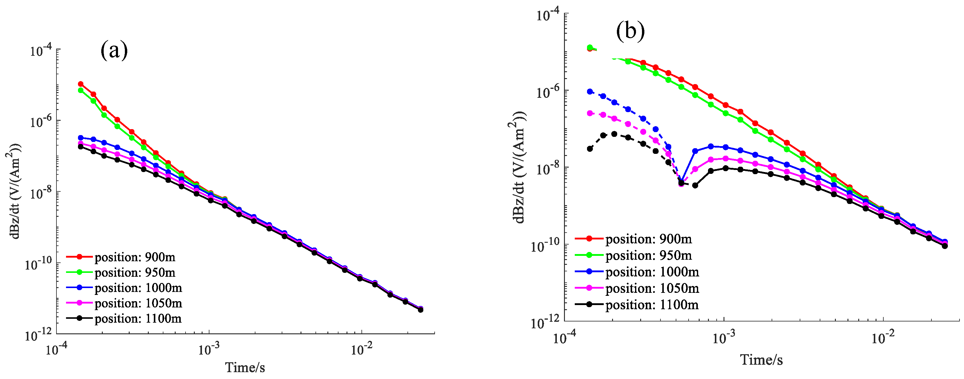
Simulations of the first group of models confirm that the large lateral contrast in conductivity can lead to sign reversals in the observed TEM data when the source loop crosses the contact interface. When the conductive terrane is 10
−2 S/m in Model 1, which has the smallest conductivity contrast, all five receivers observe positive decays (
Figure 7a). However, if the conductivity continues to increase, for example, in Models 2, 3, and 4, we start to see the sign reversals at the receivers not directly over the conductive terrane (
Figure 7b–d). The receivers above the conductive terrane always have positive decays and the decay rates reflect the change of conductivity, as expected.
Further inspection of the decay patterns for different conductivities reveals complex coupling and inductive interaction between the instrument and geological features, which give rise to diverse sign-reversed transients, including negative–positive (Model 2), positive–negative–positive (Model 3) and positive–negative (Model 4), depending on the specific geo-electric conditions (
Figure 7). These numerical simulation experiments powered by fast 3D modeling profoundly imply that the data acquired at the stations off the good conductor can also bear critical information about its conductivity, sometimes not as decay rate, but in the form of sign reversal. Such sensitivity is desirable from the perspective of pursuing high detectability; data change drastically if the model changes, but it brings serious stability issues for recoverability; the inversion may be trapped in local minimum if initiated from a background model not sufficiently close to the true answer, as shown later in this paper.
5.2. The Vertical Contact Model with a Block
Resistivity measurements of the rock samples suggest the relatively conductive Niujiaohe Formation has an average conductivity of about 0.01 S/m. However, our numerical simulations in the previous subsection require the conductive quarter-space to be about 10 S/m to have a positive–negative transient. Such high conductivity is very rare in natural rocks and in large volume. Therefore, we reasonably infer that Niujiaohe Formation may contain isolated spots of high conductivity (10 S/m), while the majority of that formation is still intermediately conductive (0.01 S/m). In order to verify the plausibility of this conceptual model, the second group of synthetic models is set up by adding a very conductive block to the quarter-space of 0.01 S/m representing the conductive terrane. The block, directly touching the resistive terrane and outcropping on the surface, measures 500, 400, and 400 m in the x-, y-, and z-directions, respectively (
Figure 8). The survey configurations and parameters remain the same as in the previous subsection.
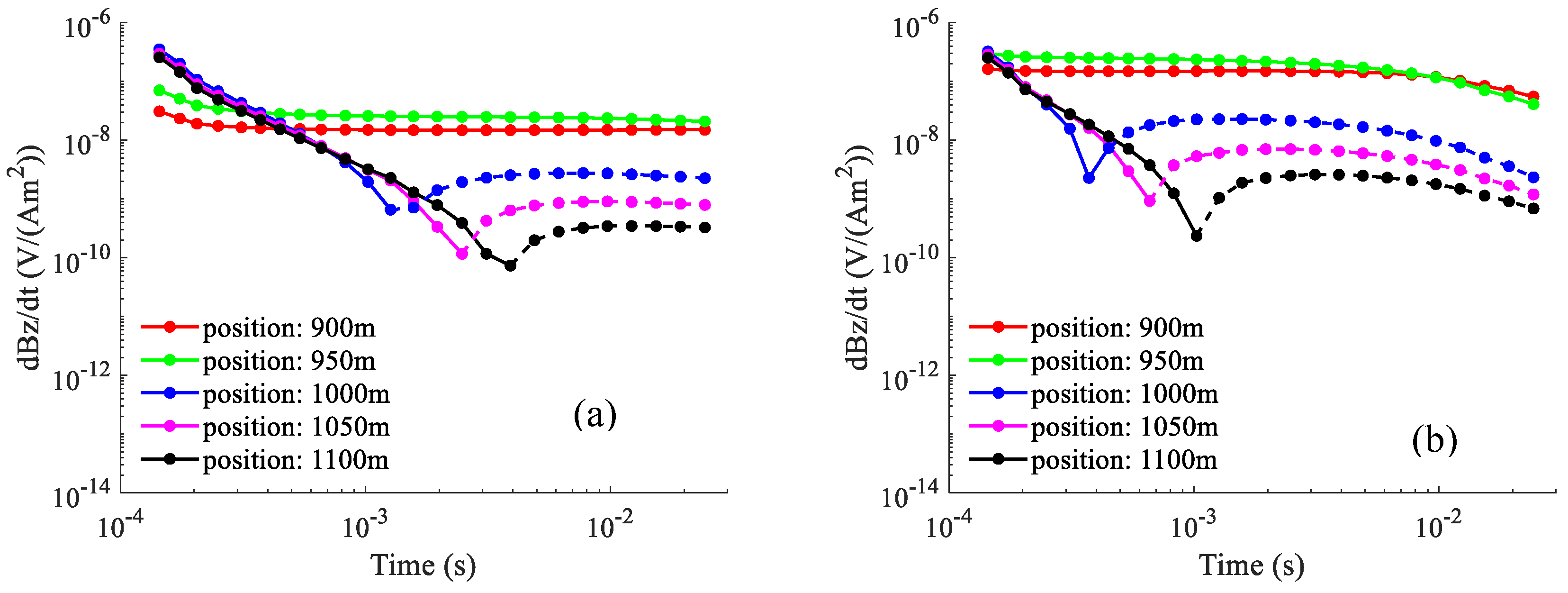
To reproduce the positive–negative transient pattern observed in the field data with a reasonable conductivity model, for the second group of synthetic models, the block’s conductivity is assigned to be 10 and 100 S/m as Models 5 and 6, respectively. The numerical setup and computing times required by these models are similar to those of Models 1 to 4.
The 3D simulation results with a block added to the contact model show positive–negative transients at the off-conductor receiver locations, whereas the data directly above the conductive block have all-positive decay, consistent with the patterns in the field data (
Figure 9). The timing of sign reversal is found to be related to the receiver position and block’s conductivity; the moment of positive–negative transition comes earlier if the receiver is closer to the conductive terrane or if the block is more conductive. In the field data, the sign reversal is usually before 10
−3 s, so Model 6 with a block’s conductivity of 100 S/m can be considered as a more representative model of the reality (
Figure 9b), although the exact boundaries of the rock units must be fine-tuned using inversions.
We acknowledge that the conductivity and the size of the block may be unrealistic. The high-conductivity block is required to qualitatively fit the field data, whereas in reality, the ground truth model can be in moderate conductivities with a complex 3D geometry. Additional simulations with buried, deeper, and smaller conductive blocks all generate positive-only transients at all of the receiver locations, which are inconsistent with the patterns in the field data. For these reasons, we consider Model 6 as the optimal candidate for the purpose of interpreting the sign reversed TEM data.
6. 3D Inversion of Field Data
The numerical simulation analyses using fast 3D forward modeling have revealed the complexity of large-loop TEM data in the presence of strong lateral variation in conductivity. Conventional interpretation techniques using apparent conductivity, decay constant or 1D layered earth inversion will certainly fail in such circumstance. Plate or block modeling can capture the first-order 3D geometric coupling between the instruments and the geological targets, sometimes correctly reproducing the sign reversal, but it lacks the flexibility of adding fine-scale and irregular structure to the model for an acceptable data fit. In this study, we demonstrate how 3D voxel inversions can play a key role in quantitatively interpreting the complex TEM field data, and how the inversion result offers critical information of geological significance.
Here, we concentrate on the data from the second and third rectangular source loops, whose data cover a range from Station 730 to 1300 at a 10-m spacing (
Figure 2). The entire dataset is assumed a 5% relative error due to random noise; the absolute noise floor is 10
−10 V/(Am
2). The TEM data over the resistive terrane decays rapidly to below the noise floor, so some late channel data, even with an accidentally high magnitude, are deemed unreliable and excluded from the inversion. Realistic digital elevation model of the survey area is obtained to build the topography in the 3D model. In general, topographical factors have a relatively significant effect on the electric field data but not so much on the dB/dt data, as the magnetic field is determined by the electric current that is continuous across lateral conductivity interfaces. As such, the topography is approximated by staircasing mesh cells; the cells in the air are assigned a constant 10
−8 S/m and fixed in the inversion.
Our 3D inversion uses a regularization of smoothness constraint based on Gauss–Newton’s method. Following the common procedure and assuming no a prior knowledge about the subsurface, we first carry out the inversion using a resistive homogeneous medium of 1.25 × 10
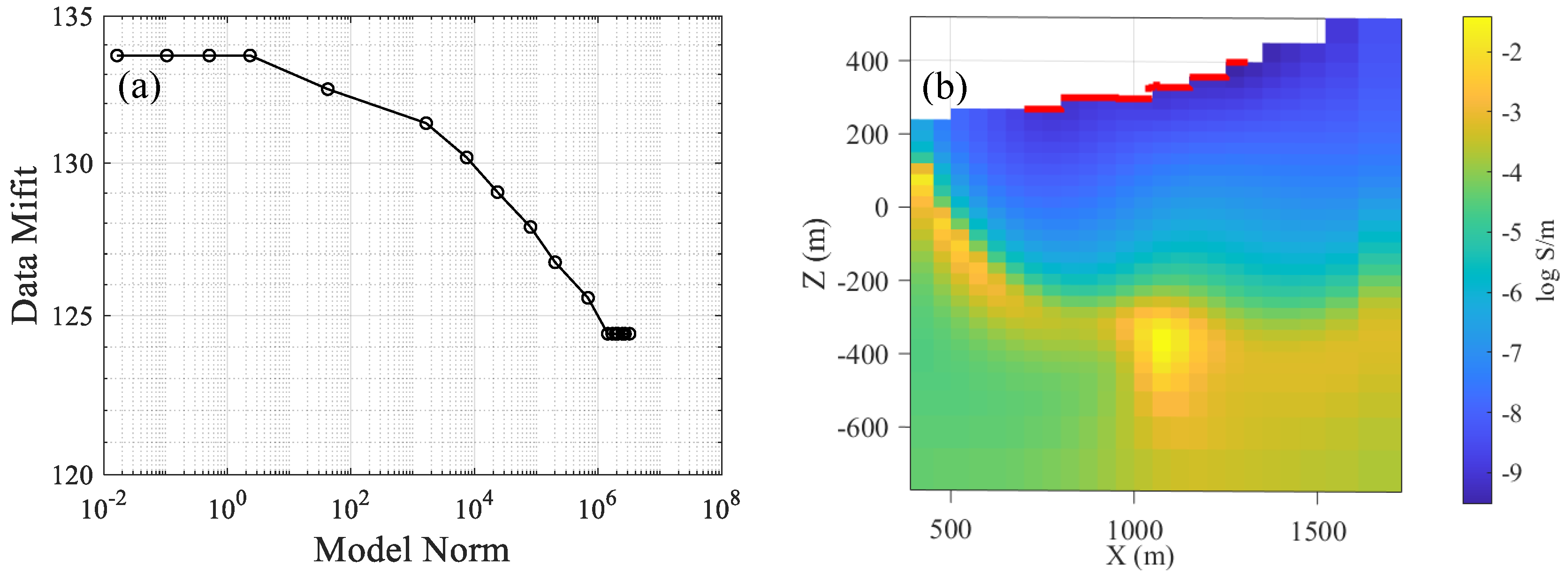
−4 S/m as the initial and reference model. The general expectation on regularized inversions solved iteratively is that the data misfit gradually reduces towards the convergence target with an increase of model complexity (model norm), reflecting a continuous transition from "poor data fit and simple model" to "good data fit and complex model". Ideally, the desired final data misfit should be approximately unity, after normalized by the total number of data. Unfortunately, in our first inversion, the convergence of data misfit stalls after 16 iterations, as the total reduction of data misfit is only 7%, although the model norm has increased from 0 to beyond 10
6 (
Figure 10a). The resultant conductivity model, with an unsatisfactory data fit, depicts a thick resistive formation overlain some conductive bulges at depth, a structure bearing no geological meaning and no indication of consistency with the expected contact between the Niujiaohe and Gaotan Formations (
Figure 10b). At such a high data misfit, the inversion completely fails to fit the decay patterns in the TEM field data. We have also investigated different conductivities (e.g. 0.01 S/m) for the initial model and found that the inversion always tends to fall into local minima.
Initiating an inversion using a homogeneous model is a reasonable and convenient choice in practice. However, we have shown that the combination of large loop and strong lateral contrast significantly complicate the data pattern, as well as the linearity and the numerical stability of the inverse problem. For example, in our first group of synthetic modeling, the time channel of 3 × 10
−3 s at Station 1100 can go from positive to negative, then to positive as the conductivity increases (
Figure 7). A gradient-based inversion does not know that keeping increasing the conductivity can lead to an even better data fit outside of the local minimum, although that means a temporarily worse fit.
Our analysis and previous experiences suggest that 3D EM inversions often need to be warm-started; starting the inversion with some pre-existing structure in the background model so the model search starts somewhere in the correct convergence domain. Such a strategy has been proven necessary and effective in 3D airborne and semi-airborne TEM inversion [
31,
32]. Our experience also shows that the warm-start model does not need to be too sophisticated, and even “about-right” models as simple as a few blocks can work well.
For the TEM field data at Shizui, to start the 3D inversion in the correct convergence domain, Model 6 in
Figure 8 is used as the initial and reference model, because it has the positive–negative transient pattern that is most consistent with that of the field data. The warm-start model consists of a resistive terrane of 10
−4 S/m and a conductive terrane made of a highly conductive block of 100 S/m embedded in an intermediately conductive background of 10
−2 S/m. The second inversion using the warm-start strategy converges after 18 iterations with a reduction of normalized data misfit from 78.56 to 1.06 and an increase of model norm by no more than two orders of magnitude (
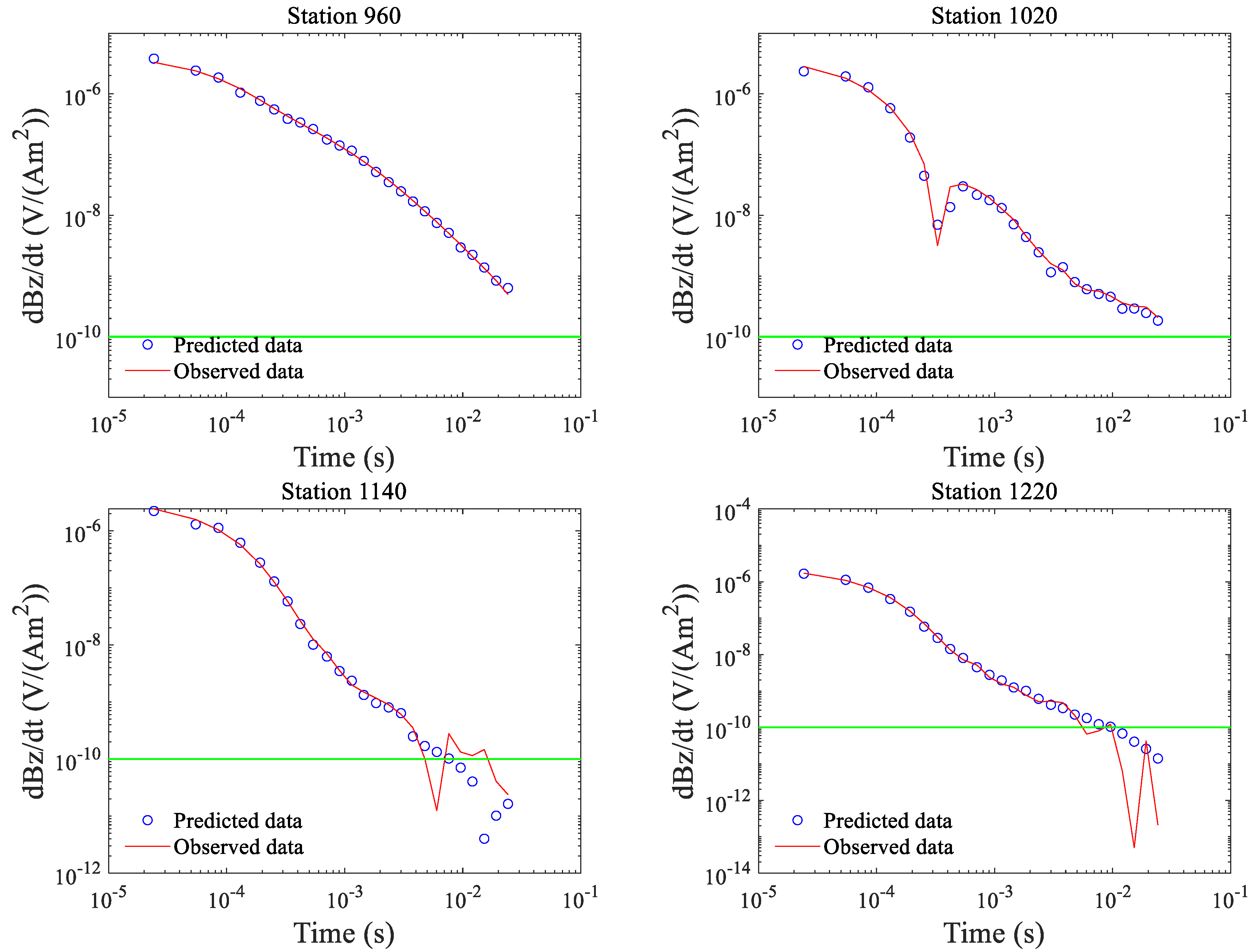
Figure 11a). The data misfit has achieved an acceptable level, as most of the decay patterns from both the conductive and resistive terranes have been well-fitted (
Figure 12). In particular, we note that the positive–negative decay at Station 1020 is precisely reproduced with the correct time of sign reversal. The possibility of inverting the field data with both conductivity and chargeability models will be explored in future.
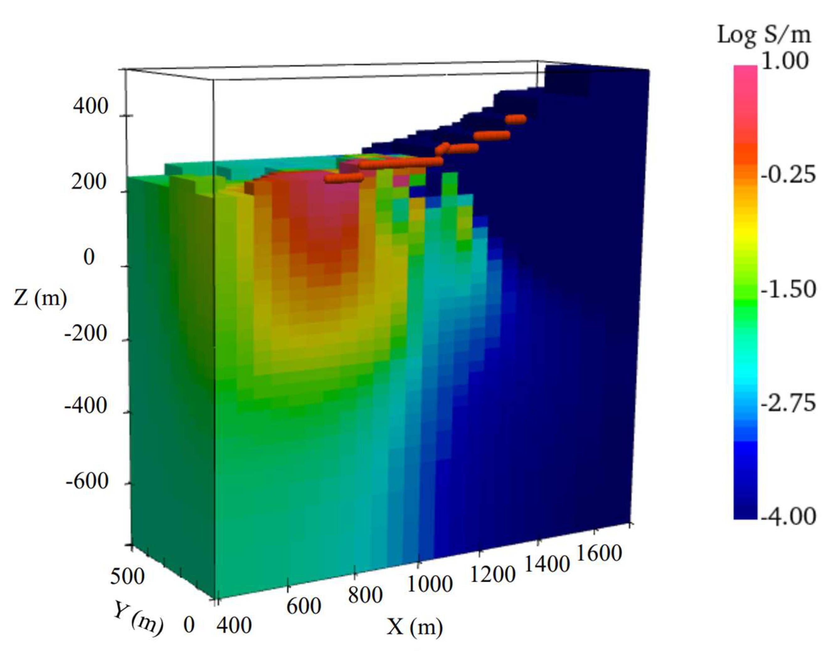
The recovered 3D model, as shown on the cross section below the survey line, clearly distinguishes two stratigraphic units of significantly different conductivities and their contact interfaces (
Figure 11b). The first-order structure of the inversion model is consistent with the warm-starting model, but with local adjustment and smoothing required by fitting the field data and by the L2-norm in the regularization term. The final model, compared with the starting blocky model conceptually constructed, is much more natural and realistic. The geological contact characterized by two conductivities is interpreted as the boundary between the Niujiaohe and Gaotan Formations, and is believed to be associated with the mineralization processes of hydrothermal alteration. The conductivities in our model are sometimes unrealistically high, and do not match the values of rock samples. There can be many possible reasons. For example, the available data are only from a single survey line, so the recovered model can be an equivalent representation of the true model with much more complicated 3D features. Additional survey data and geological constraints can help refine the model in future.
Our delineation of the 3D structure of the contact a few hundred meters below the surface provides critical morphometric information about the alteration for understanding the mineralization and its economic potentials (
Figure 13). As an independent verification, we obtain another geo-electric model reconstructed using CSAMT (controlled source audio magnetotelluric) data (
Figure 14). The CSAMT cross section suggests a similar conductivity structure, since the vertical contact near Station 1000 is clearly shown from near surface to depth, and the vertical and horizontal ranges of the high conductor are close to those in the TEM model. The CSAMT model is relatively rich in small-scale variations in conductivity, partly because CSAMT data involve measuring the electric field data, which is known to be very sensitive to the local near-surface inhomogeneity. But the rectangular-loop TEM generally has higher efficiency in field work. The recovered conductivity contrast is located close to the F1 fault on the geological map (
Figure 2). As far as we know, the F1 fault is mainly inferred from the surface outcropping, and there is no accurate geological information about its geometry and extension. Detailed study on the F1 fault would require additional geophysical and geological information in the future.
7. Conclusions
3D forward modeling and inversion are maturing and ready for use in the practice of mineral exploration. However, the computational costs and the ill-posedness of the inverse problem still make the rigorous 3D interpretation less accessible for practitioners. This paper contributes to the literature of 3D inversion application by presenting an inspiring case study on a large-loop TEM data from Shizui polymetallic mining area in Guangdong Province, China. The TEM data, acquired using large fixed rectangular loops and near-central-loop configuration, have complex and unusual transient decay patterns, including positive–negative sign reversals near the known boundary of two geological formations. Such a decay pattern cannot be fully explained by conventional interpretation methods, so we demonstrate how 3D TEM forward and inversion techniques can be applied here.
In particular, we develop a numerical framework, called survey decomposition, to carry out fast and parallel 3D simulations of arbitrary models and configurations in seconds or minutes. The fast 3D modeling algorithm facilitates our investigation of TEM sign reversal by quickly simulating and analyzing a number of representative synthetic models made based on prior geological and geophysical knowledges. Our 3D modeling finds that when the source loop crosses a contact of drastically different conductivities or encircles a good conductor, the receivers off the conductive terrane can observe the phenomenon of negative transients or sign reversals. In addition, the pattern of sign reversals can be very complex and nonlinear, depending mostly on how conductive the conductive terrane is. Such sensitivity of the off-target data, however, brings significant difficulties in convergence for 3D inversions, as we have shown that starting with a uniform medium subsurface can lead the inversion to a stuck in local minima and erroneous models. Because the gradient-based 3D inversion needs strong a priori information to initiate the inversion in the right convergence domain, we adopt one of the conceptual blocky models built during the forward modeling exercise as the initial and reference model to “warm-start” the inversion. The warm-start model, despite its simplicity, successfully captures the critical structure of the vertical contact between two formations and leads to an inversion with a good performance of convergence and a 3D conductivity model consistent with most known geological and geophysical information, including another conductivity model independently obtained from CSAMT data. The vertical contact structure delineated by our 3D inversion, especially at large depth, provides mineral exploration with critical information about the process and extent of hydrothermal alteration during mineralization. This application shows that 3D forward and inverse modeling, being the state-of-arts, can nowadays effectively and efficiently solve exploration problems in geologically complex areas and offer accurate quantitative evidences for the search of minerals. The workflow described in this paper can also serve as a template to further promote the application of 3D exploration techniques in the mining industry.
