Article

Research on Roof Load Transfer by Passing Coal Pillar of Working Face in Shallow Buried Closely Multiple-Seam

1
College of Safety Science and Engineering, Xi’an University of Science and Technology, Xi’an 710054, China
2
College of Energy Engineering, Xi’an University of Science and Technology, Xi’an 710054, China
3
Key Laboratory of Western Mines and Hazards Prevention, Ministry of Education of China, Xi’an 710054, China
4
Key Laboratory of Mine Geological Hazards Mechanism and Control, Ministry of Natural Resources, Xi’an 710054, China
*
Authors to whom correspondence should be addressed.
Minerals 2023, 13(1), 118; https://doi.org/10.3390/min13010118
Submission received: 29 October 2022 / Revised: 1 January 2023 / Accepted: 9 January 2023 / Published: 12 January 2023
(This article belongs to the Special Issue Green Mining of Coal Mine in China)

Abstract

:
The dynamic load effect of supports is mainly caused by the movement of the roof structure and the load transfer of overburden. In view of the practice issue that the phenomenon of strong ground pressure is easy to happen, when the working face of the lower coal seam passes the inclined coal pillar in shallow buried closely multiple-seam, it will lead to supprot damaged. This paper takes the mining of over-inclined coal pillars in the 22410 working face of the Bulianta Coal Mine as the background, based on the research method combining the field measurement, physical simulation experiment, and numerical calculation, the evolution law of the front abutment pressure (FAP) and roof weighting in mining under the inclined coal pillar is analyzed, and the mechanism of the stress transfer of the inclined coal pillar and the dynamic load of the support is revealed. The research shows that the concentrated stress of the coal pillar is jointly borne by the front coal wall of the working face and the interburden structure above the support. The vertical stress transmitted from the coal pillar to the floor acts on the key blocks of the interburden of the lower coal seam, which causes strong pressure and dynamic load effect, such as roof structure cut-off. The periodic breaking of the key stratum of the interburden leads to the development height and range of the cracks increasing stepwise. The partition characteristics of the mutual transformation of the interburden stress, the FAP, and the working resistance (WR) by passing the coal pillar stage are revealed, which is divided into three stages and four regions. With the working face passing through the inclined coal pillar, the influence area of the concentrated stress of the coal pillar is reduced, and the peak stress of the coal pillar is gradually transferred to the outside of the coal pillar. When the working face is 5 m away from the coal pillar, the peak of FAP and WR reaches the maximum values, the roof is cutting along the peak stress line, and the working face has a strong weighting phenomenon. The research results are consistent with the field measurement results, providing a reference for the mining of working faces under similar conditions.

1. Introduction

Underground mining of shallow coal seams is mainly distributed in China [1,2], the USA [3,4], Poland, Australia, the UK, India, etc [5,6,7,8]. The practice of mining in shallow coal seams shows that the dynamic pressure is obvious during the mining process, and the roof is performed for strong mining such as step sinking. During the mining of shallow multiple-seam, most foreign countries (American, India, etc.) use room and pillar mining methods, but research about the longwall mining method is relatively scarce [9,10,11]. For example, regarding the dynamic load in room and pillar mining, Haycocks et al. [12] study the active interaction results when mining of the lower seam is extensive enough to significantly alter the passive loading of the lower seam. Poulsen [13] described a method for calculating the load acting on a pillar of coal in a roof-and-pillar mine. Singh and Guy et al. [14,15] studied the factors affecting parting or interburden stability, for example the thickness, horizontal stresses, rock mass rating, and the extraction ratio. Das et al. [16] obtained the confining stress in the coal pillar and the corresponding peak stress at the time of its failure using a rock mass failure criterion. Frith [17] and Quang et al. [18] analyzed the stability of the coal pillar and proposed the calculation method for different coal pillar loads. Yang et al. [19] concluded that the rotary instability of the key block easily leads to the impact load in the room and pillar mining. Rashed et al. [20] monitored the stress transfer and load shedding on coal pillars, and quantified the rib deformation due to pillar retreat mining. Tuncay et al. [21] constructed a new equation for the calculation of abutment angle for moderate and deep cover cases and tested for its applicability in retreat room and pillar mines in USA and Australia. Zhu et al. [22] studied the main roof bends resulting in load redistribution among the overlying pillars.
In recent decades, with the exploitation of coal resources in China, it has gradually entered the mining of multiple-seam. The main coal seams are 2~3 layers, the interburden thickness is generally 20~60 m, it belongs to shallow closely distance multiple-seam. Currently, the main problems are the mechanism of support dynamic load and the stress transfer in the process of lower coal seam mining. Huang [23] established the structural models of a “stepped voussoir beam” and put forward the load transfer factor [24,25,26,27,28]. Xu et al. [29,30,31] studied the influence of gully terrain on the dynamic load of shallow coal seam stope, and concluded that the roof cutting and strong dynamic load when passing through the uphill section of gully terrain. Li et al. [32,33,34] investigated the relationship between mine in situ stress and mine geological structure, and the effect of original rock stress on floor water inrush. Dong [35] concluded the elastic deformation of near-field surrounding rock mass was the necessary condition for the load transfer of multiple pillars. Chen et al. [36,37] studied the dynamic load effect of the support when the roof is cut down along the coal wall. Zhu et al. [38] investigated the failure of the chamber coal pillars that causes the sudden break and even rotation of the key strata. Feng et al. [39] studied the structure of the upper and lower thick key stratum roofs. Yu et al. [40] found the causes of the strong ground pressure are the overall large cutting movement of the coal pillar in longwall mining.
Scholars have conducted relevant research on the law of ground pressure, coal pillar stress transfer, the mechanism of dynamic pressure, and the prevention of passing the coal pillar in shallow multiple seams. The authors use refined physical simulation to grasp the law of weighting regularity and the load transfer by passing the coal pillar, and the physical experiment adopts ultra-thin pressure sensors and a wireless pressure sensor to record the stress of the mining process in real time, the numerical calculation to analyze the evolution characteristics of the FAP, it can reveal the mechanism of roof load transfer by passing coal pillar. This research results can explain the mechanism, location, and conditions of the occurrence of strong ground pressure, meantime, in order to further optimize the parameters of strong ground pressure treatment technology, improve the treatment effect, and provide the scientific basis for reducing some safety accidents by passing coal pillar of working face in shallow buried closely multiple-seam.

2. Physical Simulation Experiment

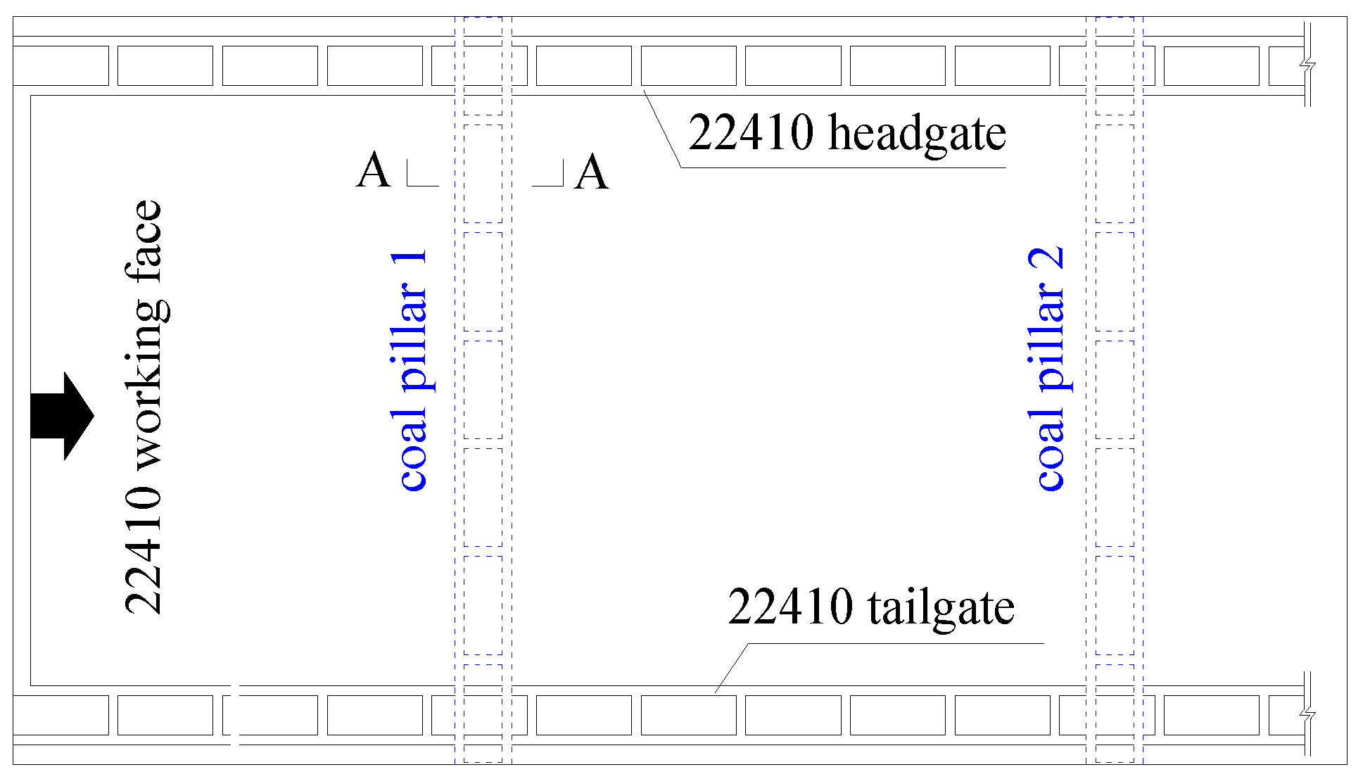
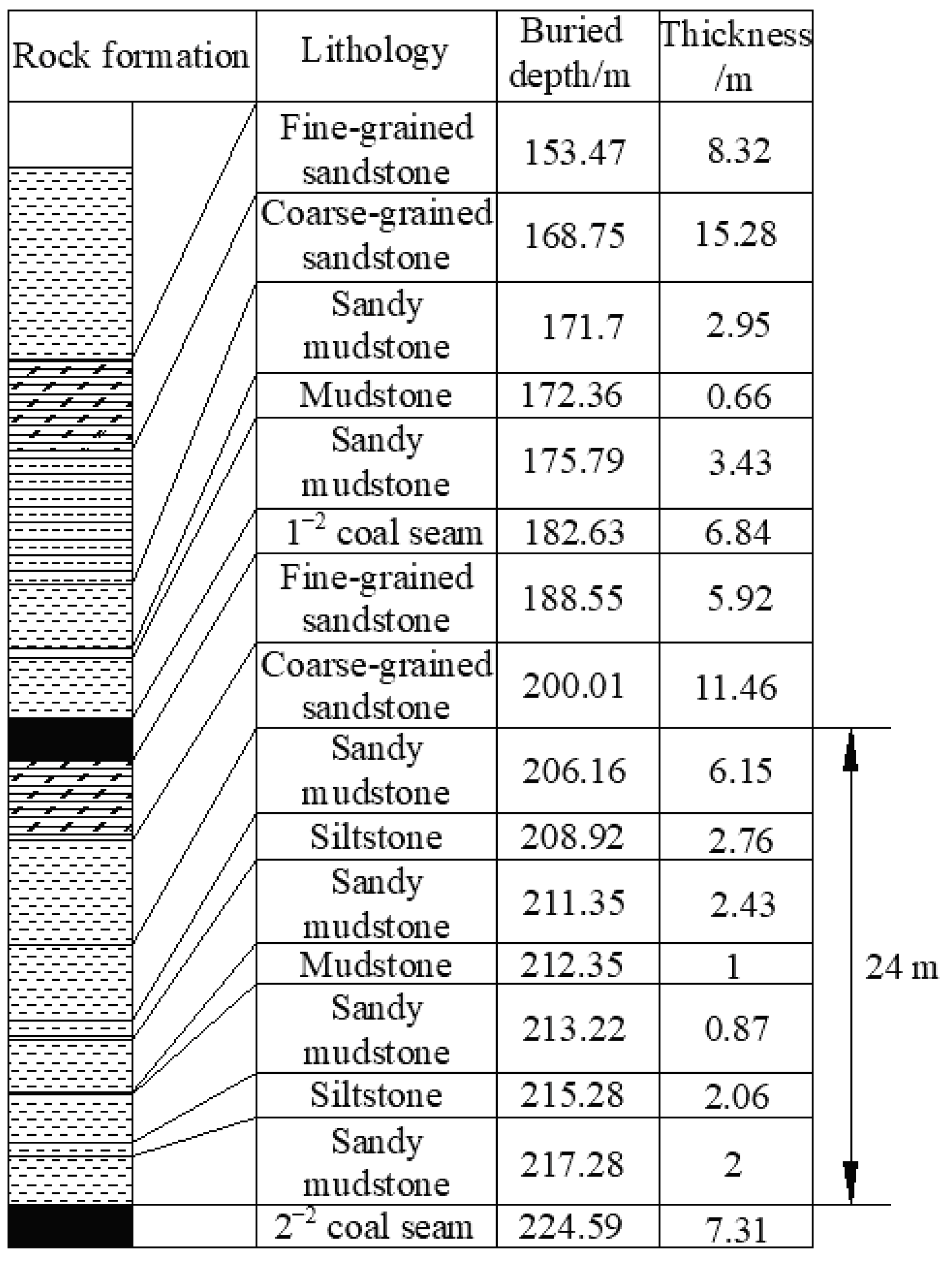
2.1. Overview of the Background

The 22410 working face is located in the 2−2 seam of Bulianta Coal Mine, Ordos, China. The mining height is 6.6 m, the working face length is 301 m (Figure 1), the buried depth is 210 m, and the interburden thickness between the 2−2 coal seam; the 1−2 coal seam is 40 m (Figure 2). The immediate roof of 2−2 coal seam is siltstone, with an average thickness of 6.64 m; the main roof is medium sandstone with a thickness of 1.55~13.27 m. It is calculated that there is a single key stratum in the interburden. The 22410 working face uses ZY21000/33.5/70D support, the rated support resistance is 21,000 kN/frame, and the initial support resistance is 16,544 kN/frame.
According to the geological mining conditions of the 22410 working face, we select the No.b280 borehole in the working face to establish the physical model (Figure 2). Through the physical simulation, we studied the law of interburden structure and the characteristics of dynamic load transfer by passing coal pillars in shallow buried closely multiple-seam.

2.2. Monitoring Methods of Interburden Structure and Load Transfer

The 22410 working face is the geological prototype, the similarity ratio is 1:150, the model size is 3 m (length) × 0.2 m (width) × 1.35 m (height), other bedrocks are used for the equivalent load instead, as shown in Figure 3. The material ratio of the physical experiment is shown in Table 1. Table 1 shows that the coal seam adopts the proportion of 20:20:1:5 (river sand: gypsum: white powder: fly ash), and the consumable of fly ash is 5.09 kg/cm.
The monitoring system in this physical simulation experiment mainly includes: the fracture of overburden, the working resistance, the stress and displacement of interburden, and the stress sensors and instruments for the physical experiment are shown in Figure 4.
(1)
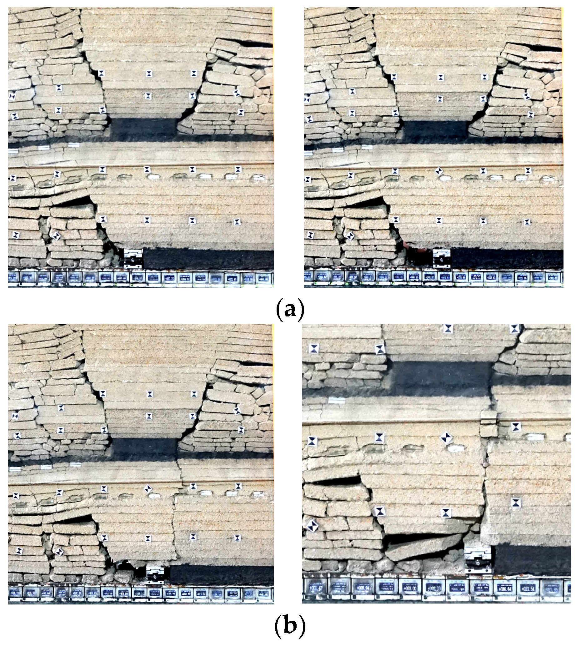
Fractured structure of the overburden: using fixed-point photography to obtain the fracture and structural characteristics of the overburden at different stages in the mining.
(2)
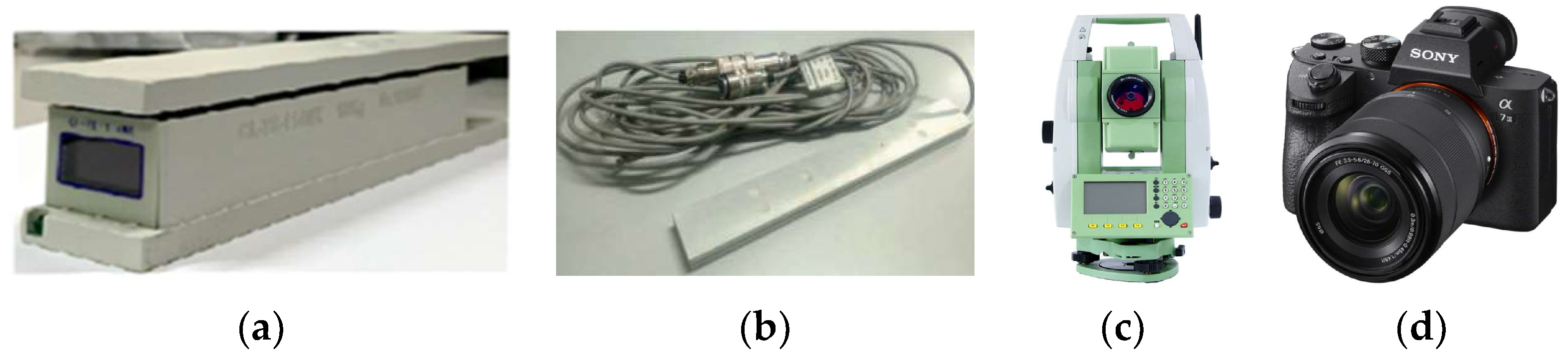
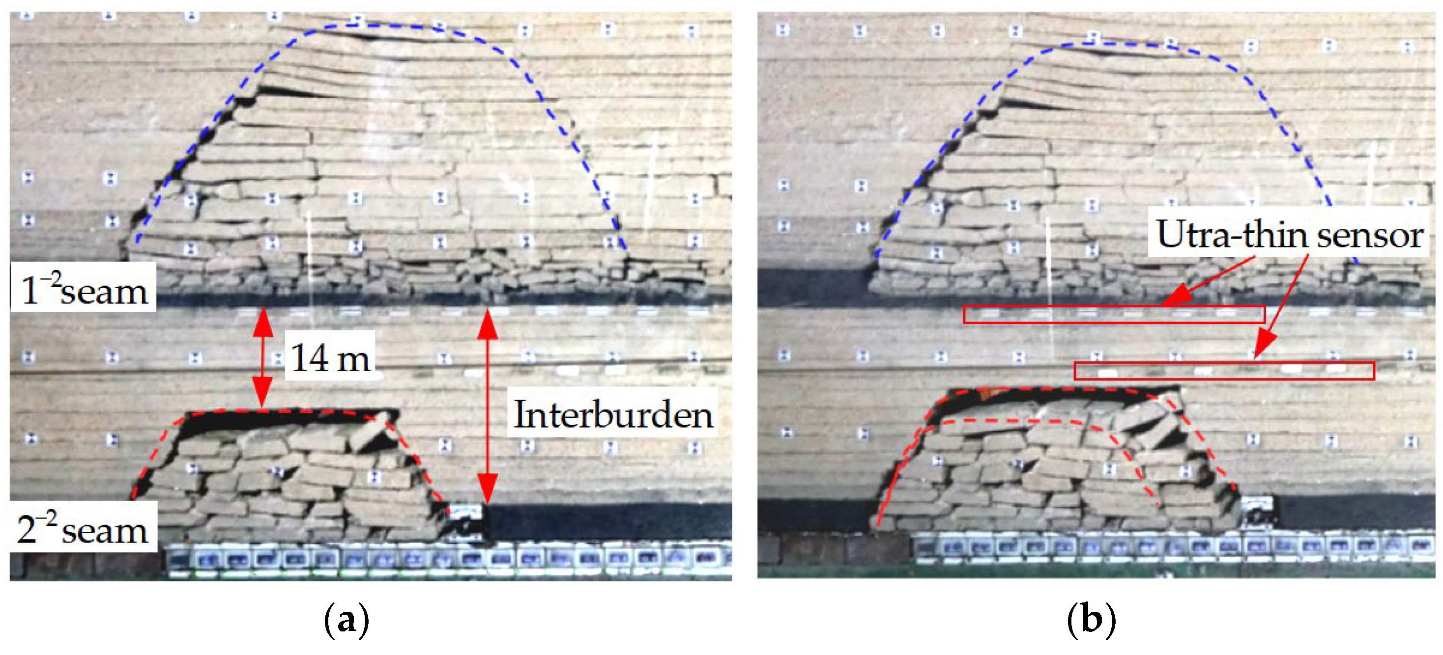
Used the ultra-thin pressure sensors (the thickness of ultra-thin stress sensor is 1 cm), to continuously monitor the law of dynamic load transfer during the mining process. The stress box and ultra-thin pressure sensors on the floor of the 1−2 coal seam every 3 cm to monitor the concentrated stress of the coal pillars in the goaf (Figure 3). The ultra-thin sensors every 3 cm at 5 cm below the 1−2 coal seam, to monitor the stress transfer of the interburden.
(3)
Used the developed wireless pressure sensor and fast data acquisition system, laying wireless pressure sensors on the floor of 2−2 coal seam to monitor the law of the FAP during the mining of the 2−2 coal seam.
(4)
Seven displacement measuring lines are arranged on the surface of the physical experiment model, and the vertical displacement of the overlying rock is monitored by a total station. Arranged from bottom to top as follows A~G, as shown in Figure 3 and Figure 4.

3. Overburden Characteristics of Upper Coal Seam Mining

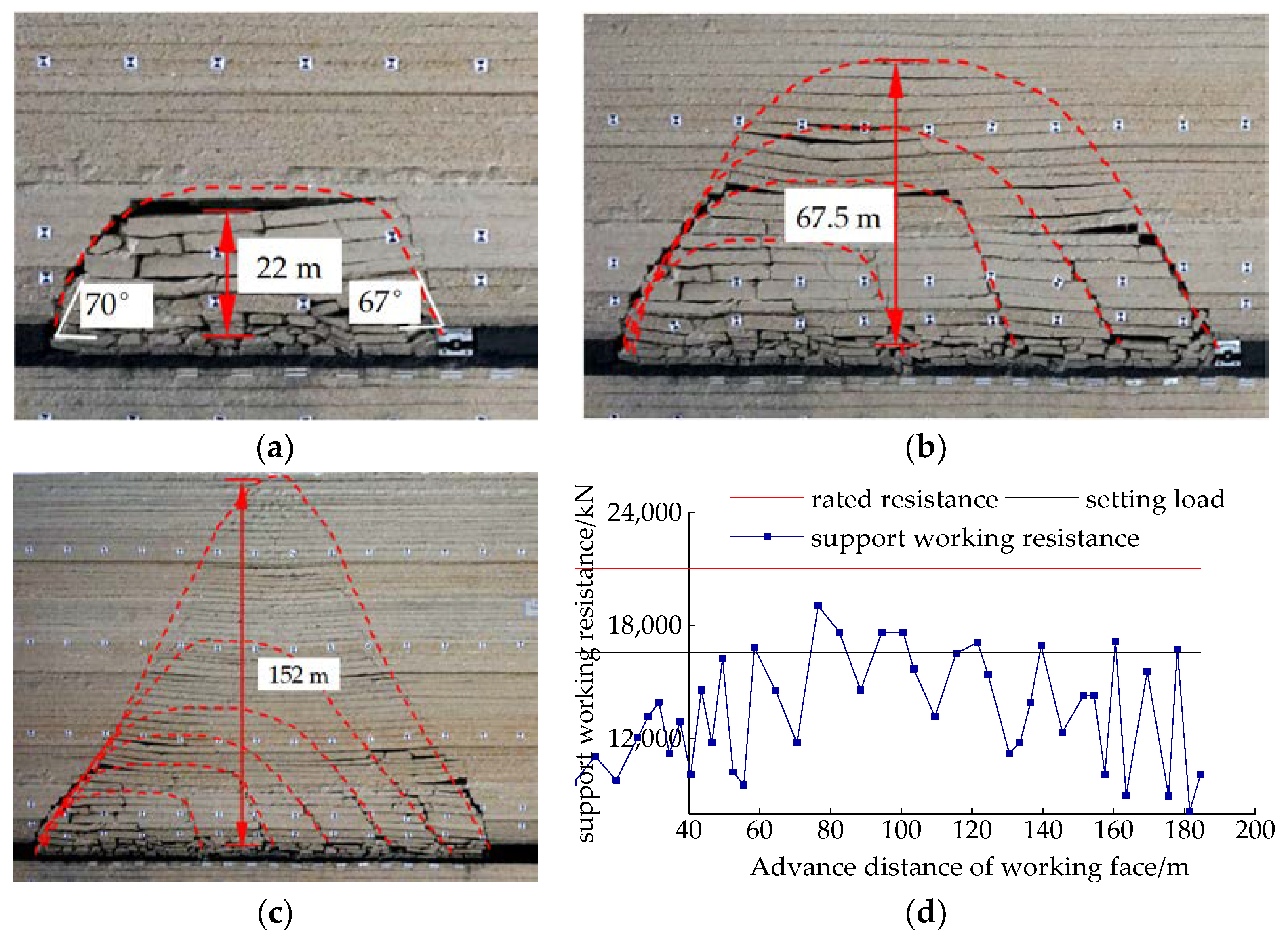
3.1. Characteristics of Roof Caving and Weighting

The physical experiment shows that during the mining stage of the 1−2 coal seams, the law of roof caving and weighting pressure are shown in Figure 5. The first weighting interval is 58 m, the average periodic weighting interval is 19.6 m, and the WR during the roof weighting is 16,730~19,040 kN/frame. Explanation: first weighting (FW), first-period weighting (FPW1), second-period weighting (SPW2), third-period weighting (TPW3), fourth-period weighting(FPW4), fifth-period weighting (FPW5), sixth-period weighting (SPW6).

3.2. Evolution of Stress Distribution in the Goaf and Coal Pillar

The stress concentration of the coal pillar is the main factor that causes the strong weighting by passing the coal pillar. After the excavation of 1−2 coal seam is completed, the stress concentration is analyzed according to the ultra-thin pressure sensors and floor pressure sensors.
By analyzing the changes in the stress concentration coefficient of the ultra-thin pressure sensor, which is in the interburden at the 24 m layer above the roof of the 2−2 coal seam. The stress of the 24 m interburden layer under the goaf is 0.62~0.76 times of the original stress, the stress under the inclined coal pillar is 1.41~1.90 times, and the average is 1.60 times, as shown in Figure 6. The maximum stress of the 24 m interburden layer is located in the middle of the coal pillar, the stress distribution in the working face under the goaf shows the characteristics of “large in the middle and small at both ends”, and the stress at both ends is affected by the coal pillars of the model boundary.

4. Physical Experiment of Characteristics of Interburden

4.1. During Interburden Unbroken Mining Process

As the working face advances to 32 m, the immediately roof caves (IRC). When the working face advances to 66 m, the main roof collapses for the first time, the working face is FW, and the WR reaches 18,800 kN/frame. The interburden collapsed height is 16.5 m. There is still 18.5 m interburden unbroken, the breaking angle of the open cut is 62°, the breaking angle of the coal rib is 65°, as shown in Figure 7a.
As the working face advances to 78 m, the main roof is FPW1. During FPW1, the WR of the support is 17,960 kN/frame, the roof collapsed height is 21 m. The thickness of the interburden unbroken is 14 m, the maximum separation is 4.25 m, and the periodic weighting interval is 12 m, as shown in Figure 7b.

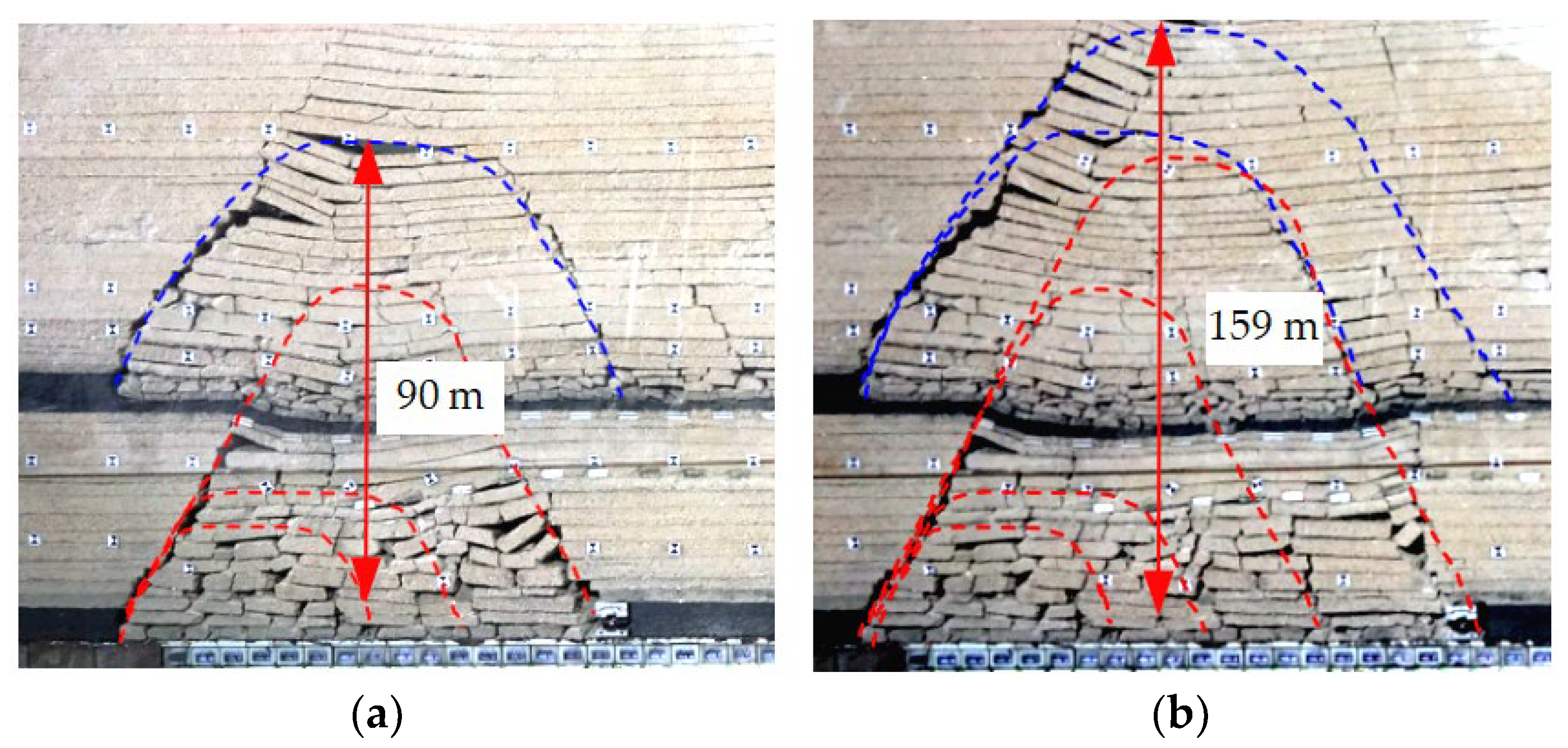
4.2. When the Interburden Is Broken, Upper and Lower Goaf Are Connected

When the working face advances to 96 m, the interburden is broken, the upper and lower goaf are connected, and the main roof is SPW2. The WR is 17,640 kN/frame, and the periodic interval is 18 m. At this time, the “activated” height of the roof in the upper coal seam has developed to 90 m, the maximum separation of the caved roof of the 1−2 coal seam is 3 m, and the roof collapse of the 1−2 coal seam is a hinged structure of “step sinking”, the upper coal seam has mined the span of the loose arch in the area is approximately equal to the mining distance of the lower coal seam, as shown in Figure 8a.
As the working face advances to 115 m, the main roof is TPW3, the WR of the support is 19,160 kN/frame, the weighting interval is 19 m, and vertical cracks appear 1~2 m in front of the support. The “activated” height of the caved roof in the goaf area of the 1−2 coal seam has developed to 159 m, and the maximum separation of the roof is 1.2 m, as shown in Figure 8b.
When the working face advances to 138 m, the main roof is FPW4 and the interburden is broken periodically, the WR is 20,920 kN/frame, and the weighting interval is 22 m, as shown in Figure 9a. As the working face advances to 156 m, the main roof is FPW5, the WR of the support is 19,360 kN/frame, and the weighting interval is 18 m, as shown in Figure 9b.
By analyzing the physical experiment of 22410 working face mining under the goaf of 1−2 coal seam, we concluded that the FW interval is 66 m, the WR at the FW is 18,800 kN/frame; the average period weighting interval is 17 m. The field measured FW interval of 22410 working face is 64.3 m, and the average period weighting interval is 15 m, the WR of the period weighting is 19,537~23,319 kN/frame, and the WR of the non-weighting is 15,756 kN/frame, the dynamic load coefficient is 1.24~1.48, as shown in Figure 10.
It shows that the results of physical simulation experiments are basically consistent with the field results, and these physics experiment results are reliable.

4.3. The Dynamic Load Evolution of the FAP and the 24 m Layer Stress in the Lower Seam Mining

Through a physical simulation experiment, the evolution characteristics of the front abutment pressure coefficient (FAPC) of the coal rib and the 24 m layer above the roof are analyzed in the mining under the goaf. FAPC factor: the ratio of the FAP at different compression moments to the original rock stress of each layer, as shown in Figure 11, the roof stress concentration coefficient (RSCC).
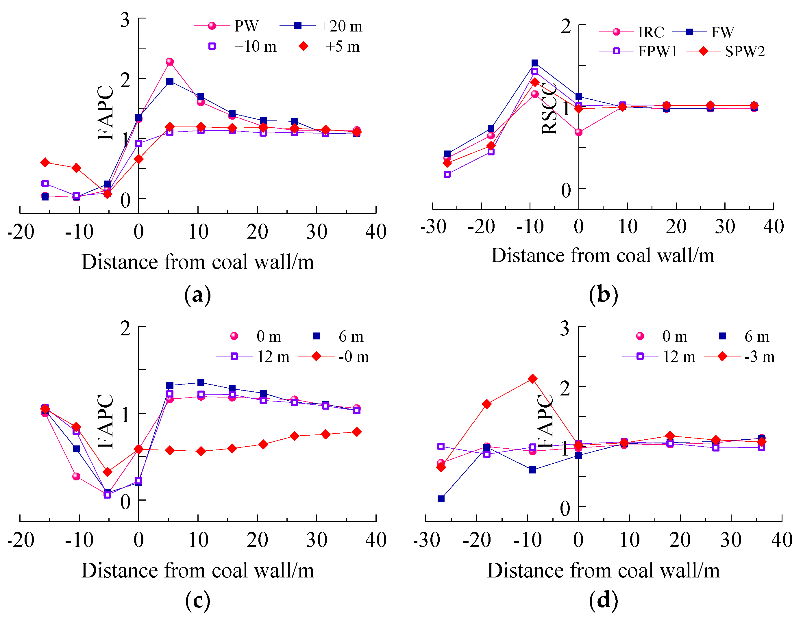
Before the interburden unbroken: during the FW and FPW1 of the lower coal seam, the FAPC increased from 1.24 to 1.56, an increase of 26%, as shown in Figure 11a. The 24 m layer RSCC is basically equal to the original rock stress, indicating that the mining has little disturbance to the interburden. During the FW period, the roof belongs to the unloading damage, and the damage of the roof develops from the low level to the high level. Under the influence of the breaking angle, the movement of high level has a certain hysteresis compared with coal rib, but the change is not significant, as shown in Figure 11b.
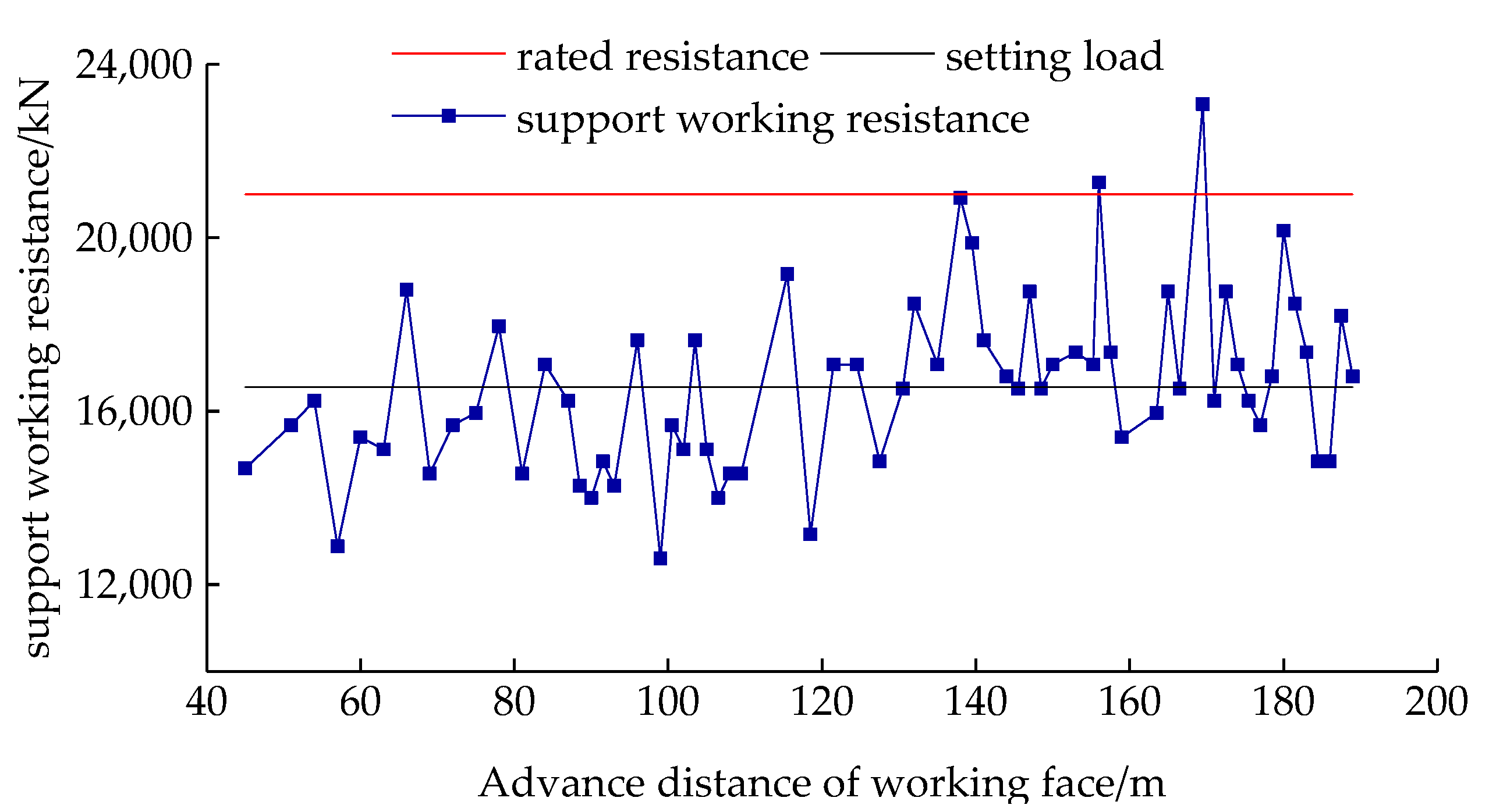
After the interburden collapsed: in the analysis of the results from the SPW2 to FPW5, we found the FAPC increased from 1.45 to 2.47, an increase of 70.3%. The 24 m layer RSCC is increased from 1.05 to 1.80, an increase of 71.4%. It is shown that after the interburden is broken, the upper and lower goaf are connected, and the load of the collapsed roof in the upper goaf will be transmitted to the lower working face, causing the WR increase, as shown in Figure 10. Combined with the physical experiment, the WR during the SPW2 is 17,640 kN/frame, and the average WR during the TPW3 to FPW5 is 19,146 kN/frame, the WR increases by 8.5%.
Experiment shows that during the period of weighting, the breakage of the interburden triggers the “activation” of the caved roof, which causes the FAP and WR of the working face to rise, indicating the “activation” of the roof has a load transfer effect on the lower coal seam mining. In addition, the RSCC of the interburden at the 24 m layer increased by 71.4%, and the FAPC increased by 70.3%, indicating that the load of the weighting is almost 100% transferred to the lower coal seam.

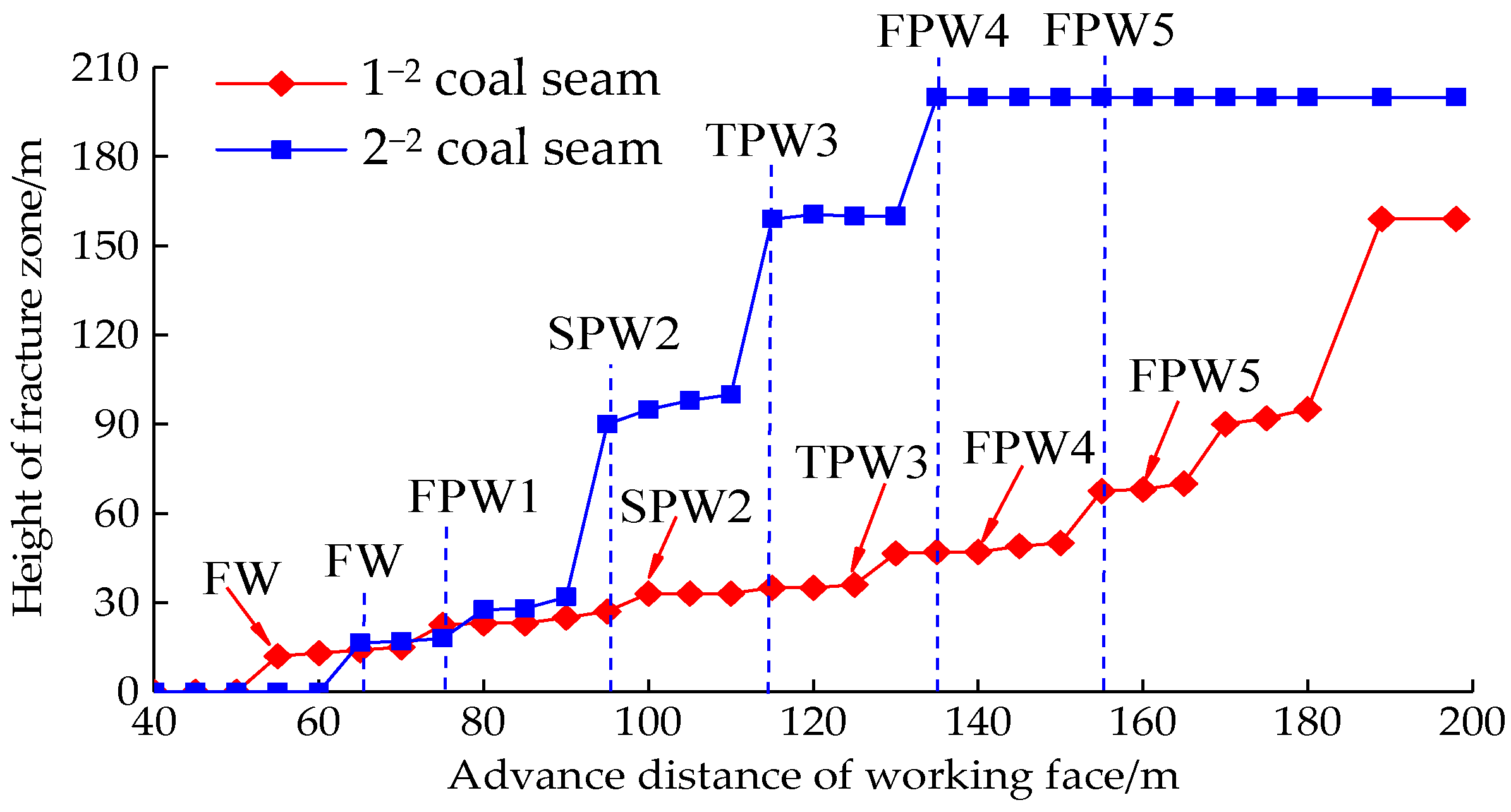
4.4. Development of the Fracture Zone

The results of the physical simulation experiment give the specific situation of the height of the crack development in the lower coal seam.
As the working face is advanced to 66 m, the overburden collapse height is 16.5 m; when the working face advances to 78 m, the overburden collapse height is 21 m; when the working face advances to 96 m, the 35 m interburden layer is completely broken, the goaf of the upper and lower working faces is connected, the “activated” height developed to 90 m. When the working face advanced to 115 m, the collapsed roof was activated, the height of the activated cracks was 159 m, and the separation cracks were widened. When the working face advanced to 138 m, the collapsed roof of the height of the activated cracks reached 200 m, reaching the surface. The development height of cracks result is shown in Figure 12.
From the statistical analysis in Figure 12, with the increase of mining distance, the height of the overburden fractured zone presents increases non-linearly. The regression equation for the height of the overburden cracks in the upper coal seam is y = 5 × 10−5x3 − 0.009x2 + 0.8013x − 12.58, and the correlation coefficient R2 = 0.9416. The developed height of the overburden fractured in the lower coal seam is: y = −0.0002x3 + 0.053x2 − 3.0022x + 33.327, and the correlation coefficient R2 = 0.9719.
After the upper and lower goaf are connected, due to the “activation” effect of the caved structure of the goaf, the development speed of the fractured zone is significantly increased by the mining activation of the working face. When the roof weighting, the development height, and range of activated fractures increase stepwise.

5. Concentrated Stress Transfer of Coal Pillars and Dynamic Load Characteristics of Supports

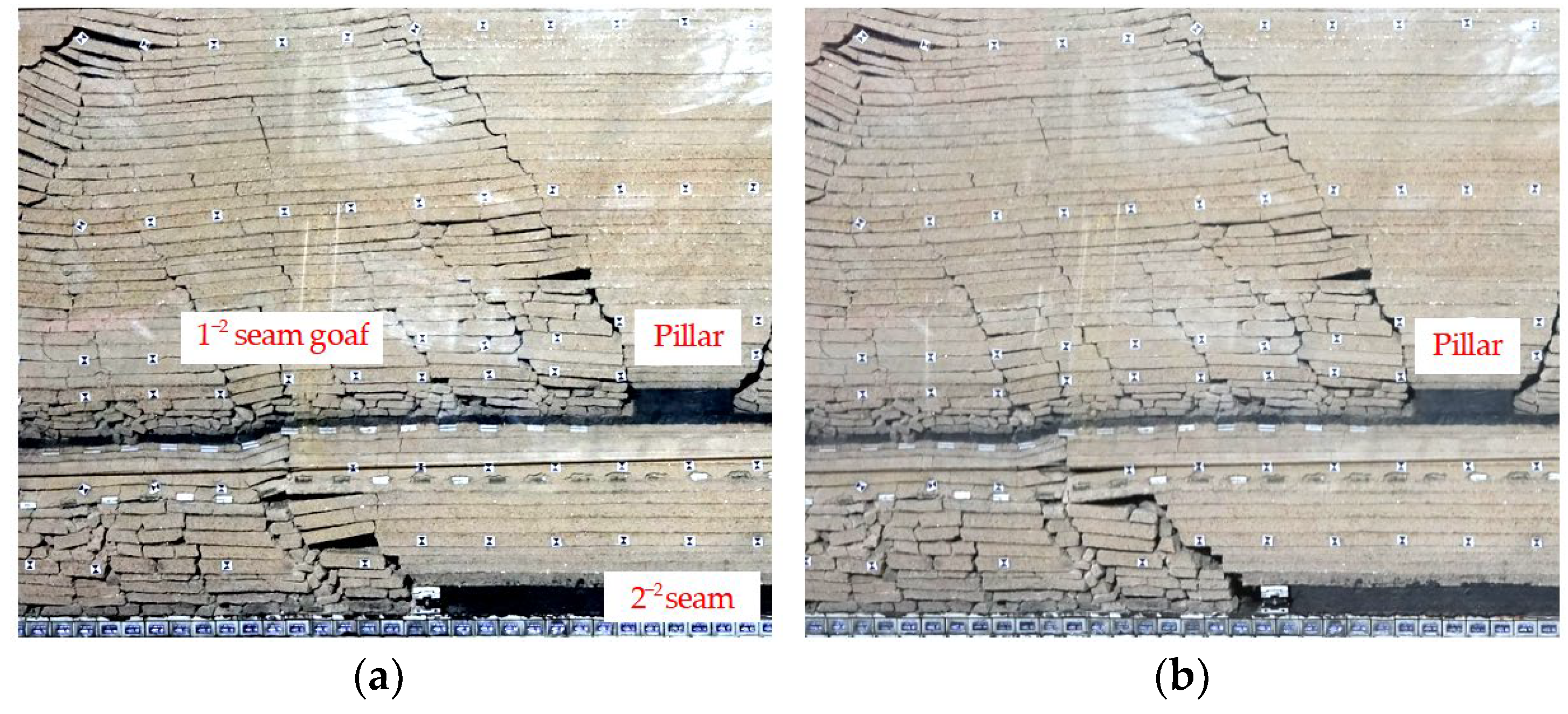
5.1. The Pressure Law of the Support at the Stage of Passing the Coal Pillar

As the working face has advanced to 169 m (15 m before entering the coal pillar), the working face is SPW6 and enters the coal pillar affected area. As the working face advances to 188 m (entering 4 m under the coal pillar), the working face is SPW7, the support resistance is 18,200 kN/frame, the period weighting interval is 19 m. The interburden was step sunk, the width of the crack was increased, and the maximum width is 4.5 m. The goaf on the left side of the coal pillar has collapsed and the caved roof has been activated to sink, as shown in Figure 13.
As the working face advances to 202 m (18 m under the coal pillar and 4 m from the coal pillar boundary), the inverted trapezoidal load above the coal pillar act on the support, and the WR increased to 28,500 kN/frame. With the 8th-period weighting, the roof is cut off vertically along the right side of the coal pillar, the support is crushed, and the roof step sinks up to 2200 mm, as shown in Figure 13b.
When the working face advances to 228 m (after the coal pillar is 22 m), the main roof collapses in the 9th-period weighting, WR is 18,660 kN/frame, and the weighting interval is 26 m. At this time, the roof behind the support collapsed through the interburden and connected to the goaf on the right side. The coal pillar and the inverted trapezoidal roof were cut as a whole, with a vertical cut of 3.3 m, as shown in Figure 14.

5.2. Law of FAPC and the 24 m Layer RSCC at the Stage of Passing the Coal Pillar

Based on the physical experiment, the evolution characteristics of the FAPC and 24 m layer RSCC by passing the coal pillar of the working face in shallow buried closely multiple-seam are analyzed, as shown in Figure 15. Figure 15 shows that −30 m represents the distance before the working face enters the coal pillar; 10 m represents the distance under the working face into the coal pillar; +5 m represents the distance after the working face out of the coal pillar.
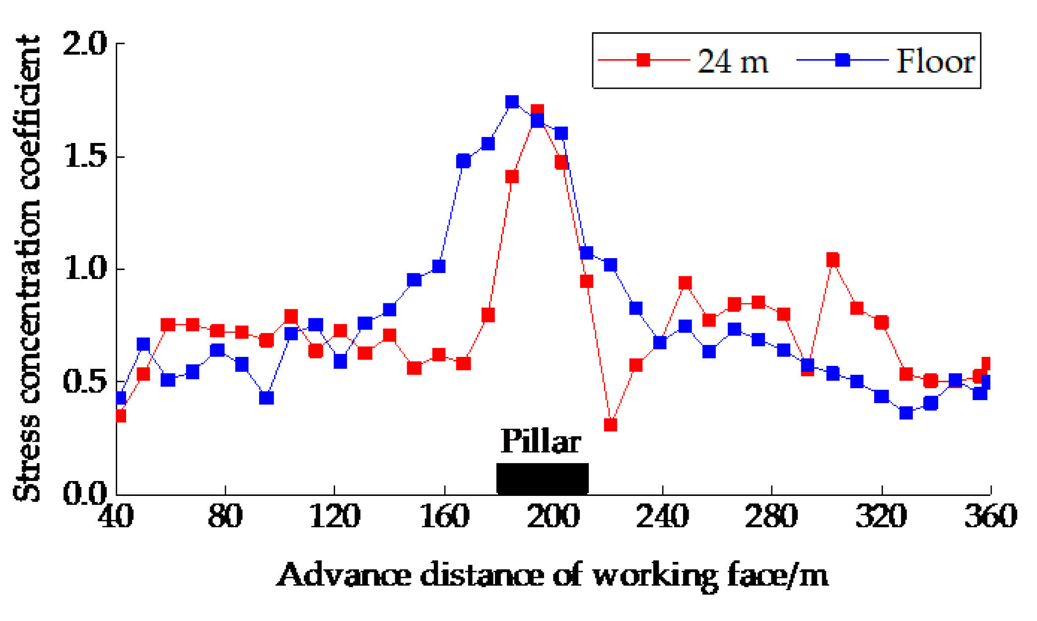
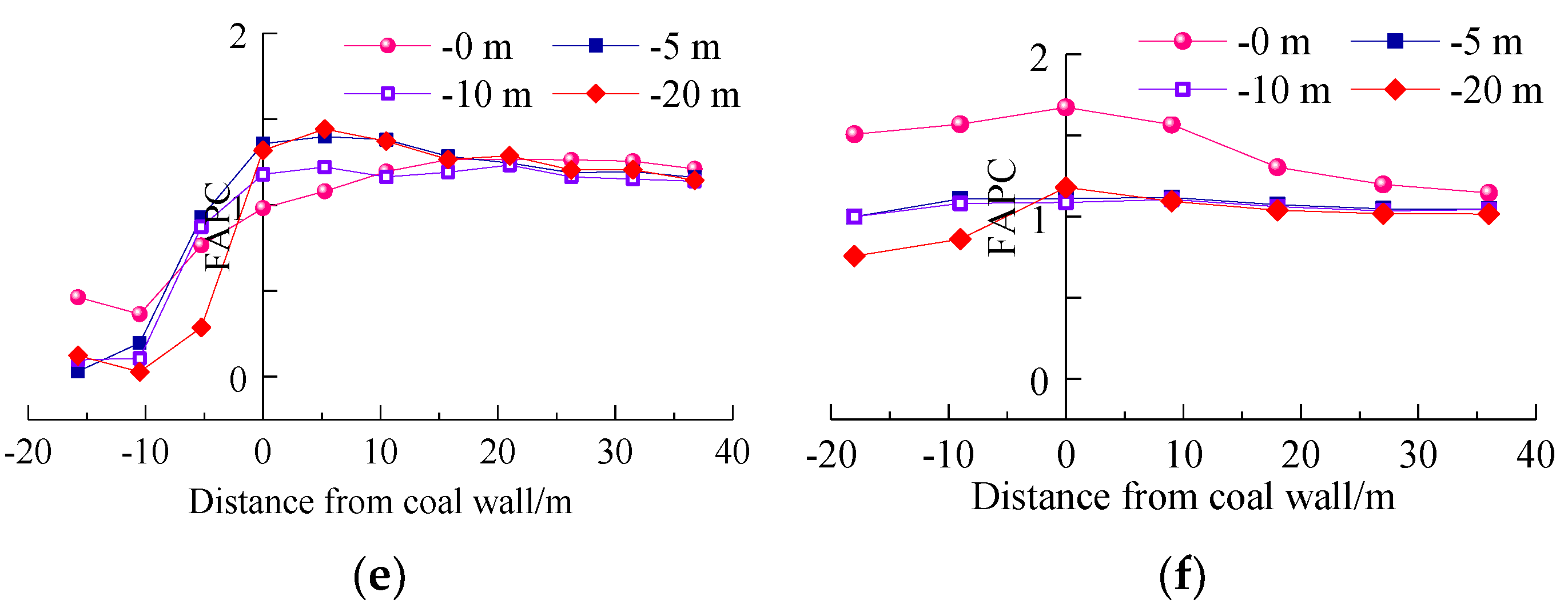
As the working face passes the coal pillar affected area, the WR slowly increases. Comparing the 20 m before entering the coal pillar and 5 m before entering the coal pillar, the peak of FAPC decreases from 1.99 to 1.19, a decrease of 40.2%. In the range of 0~10 m behind the goaf, the 24 m layer RSCC began to increase, and the peak of 24 m layer RSCC increased from 1.15 to 1.53, an increase of 33%, as shown in Figure 15a,b.
During the working face enters 2/3 the width of the coal pillar process, the WR of the support is reduced; comparing the 0 m into the coal pillar and the 3 m before the coal pillar, the FAPC remains basically unchanged. The peak of FAPC at the rear 10 m increased significantly, from 0.27 to 1.19, an increase of 40.2%. In the range of 0~10 m behind the goaf, the 24 m layer RSCC increased from 1.15 to 1.53, an increase of 33%, as shown in Figure 15a–d. At this time, the overall distribution of the FAPC and the RSCC of 24 m layer is increasing.
During the peak area of the WR; comparing the 12 m coal pillar entering and 3 m before the coal pillar, the FAPC decreases from 1.22 to 0.57, a decrease of 53.3%. The peak of 24 m layer RSCC increased from 0.99 to 2.13, an increase of 115%, as shown in Figure 15c–f. It shows that during the coal pillar stage, the FAPC is reduced, the 24 m layer RSCC is increased, and the load of the interburden is increased, which is the main reason for the increase of the WR.
When the working face passes the coal pillar, the WR slowly decreases. Comparing the coal pillar 0~20 m, the FAPC increases from 1.08 to 1.44, an increase of 33.3%, the 24 m layer RSCC is reduced from 1.6 to 1.09, a decrease of 31.9%. We compare past the coal pillar 5 m and 20 m, the FAPC and RSCC basically remain unchanged, as shown in Figure 15e,f. It needs to be dealt with in production practice, we should reduce the sinking space and the weighting interval of key stratum, make better use of the self-supporting capacity of surrounding rock and reduce the pressure of the period weighting.
In order to ensure the safety mining, during the mining process of the lower coal seam, the 10 m range before and pass the coal pillar should be regarded as the key area of dynamic pressure prevention and control. By strengthening the observation of weighting and ensuring the support quality, we can avoid dynamic pressure disaster accidents.

5.3. Load Transfer and Stress Evolution

Based on the above analysis, during the mining of working face passing through the coal pillar, the coal pillar stress has a transformation process to the FAPC, the stress concentration interburden, and the WR, which can be divided into 3 stages and 4 areas, as shown in Figure 16, the details as follows:
(1)
Before the coal pillar (coal pillar affected area to the coal pillar boundary): FAP reduce—WR increase. Before the working face into the coal pillar −htanθ~0 m (h is the thickness of the interburden, h = 35 m; θ is the stress transmission angle, θ = 25°, htanθ = 16, in Figure 16). The stress of the coal pillar is mainly transmitted in FAP, and the FAP begins to rise significantly.
(2)
Entering the stage of the coal pillar (under the coal pillar): FAP increases—WR decreases. The working face enters the coal pillar 0~htanθm (approximately equal to 2/3 the width of the coal pillar). The stress transferred by the coal pillar is concentrated on the coal rib, leading to the FAP increases, and the WR decreases.
The peak of the FAP—WR increase conversion zone (the working face is located from 2/3 of the coal pillar to the boundary), entering the center of the coal pillar affects the area. This is due to the fact that most of the stress transferred by the coal pillar is concentrated on the FAP and support. FAP in the early stage increases to the peak value, and the WR increases significantly in the later stage.
(3)
Out coal pillar stage (from behind the coal pillar boundary to the coal pillar affected area): WR increase—FAP reduce. When the working face is approaching the coal pillar stage, the coal pillar and overlying rotate and sink with the lower working face, and most of the stress is transferred to the roof structure behind the coal rib, resulting in the WR still being larger, and the FAP begins to decrease.
The physical simulation experiment shows the 22410 working face are mined under the goaf, showing large and small periods of pressure; when the working face is mined under the coal pillar, it will have strong weighting, the location of strong weighing is about 4 m away from the coal pillar boundary. In the coal pillar’s influence zone, the interburden will break in advance of the coal rib, when the working face advances to the advanced breaking line, it will cause the roof to cut and fall, and strong ground pressure to appear on the working face.
Field measurement results of coal pillar 1 (as shown in Figure 1): the working face is 5 m away from the coal pillar, the working face is period weighting, and the WR is 20,463 kN/frame. When the working face is 3 m under the coal pillar, the roof was broken, and the WR is 21,415 kN/frame. As the working face enters the coal pillar 8 m, the WR increases 22,843 kN/frame, and the column of the 64# support drops 1200 mm instantly. The physical simulation experiment is basically consistent with the field measurement results.

6. Numerical Simulation of Load Transfer and Stress Evolution

Taking the 22410 working face as the background, the mining height of 1−2 coal seam is 5 m, the mining height of 2−2 coal seam is 6.6 m, the average thickness of the interburden is 35 m, the width of coal pillar is 25 m, the numerical simulation model size is 550 m (width) × 238 m (height), the left and right boundaries are left 80 m boundary. We use the Mohr-Coulomb model, the free boundary is set at the top, the normal horizontal displacement constraint is set on the left and right sides, and the normal vertical displacement constraint is set on the bottom plate. The coal pillar unit division is fine, the division unit cell is 1 m × 1 m, and the interburden division unit cell is 3 m × 3 m, 2−2 coal seam original rock stress is 6 MPa.

6.1. Interburden Stress by Passing the Coal Pillar
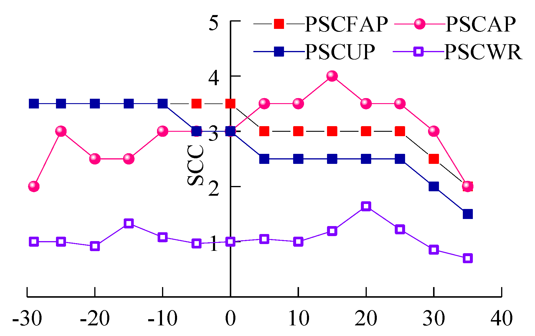
When the working face is 25 m before the coal pillar (Figure 17a): the FAP is 15 MPa, it’s 2.5 times the original rock stress, and the influence range of FAP is about 16 m.
When the working face is 15 m before the coal pillar (Figure 17b): the working face into the coal pillar influence area, the coal pillar stress transfer angle is 25°, the FAP stress increased significantly, and the peak value and influence range of FAP remain unchanged.
When the working face into the coal pillar 0 m (Figure 17c): the FAP increased to 18 MPa, which is 3.0 times the original rock stress; the peak of FAP increased 20%, and the peak influence range increased by 25%.
When the working face into the coal pillar is 10 m (Figure 17d): the peak of FAP increased to 21 MPa, which is 3.5 times the original rock stress, with a stress influence range of 16 m. As the working face into the coal pillar is 20 m (Figure 17e), the peak of FAP is reduced to 16 MPa and the peak stress range is significantly reduced. At this time, the maximum stress concentration of the coal pillar is close to the boundary of the coal pillar.
According to the numerical analysis results, it is concluded that the concentrated stress of the coal pillar will be borne by the advanced coal wall and the roof structure above the support in the process of mining. In different stages of the coal pillar, the concentrated stress of the coal pillar is mainly transferred from the interburden in front of the coal wall and gradually transformed into the roof structure behind the coal wall. That is, there is a dynamic transformation process between FAP and the concentrated stress of the coal pillar, and results are shown in Figure 18.
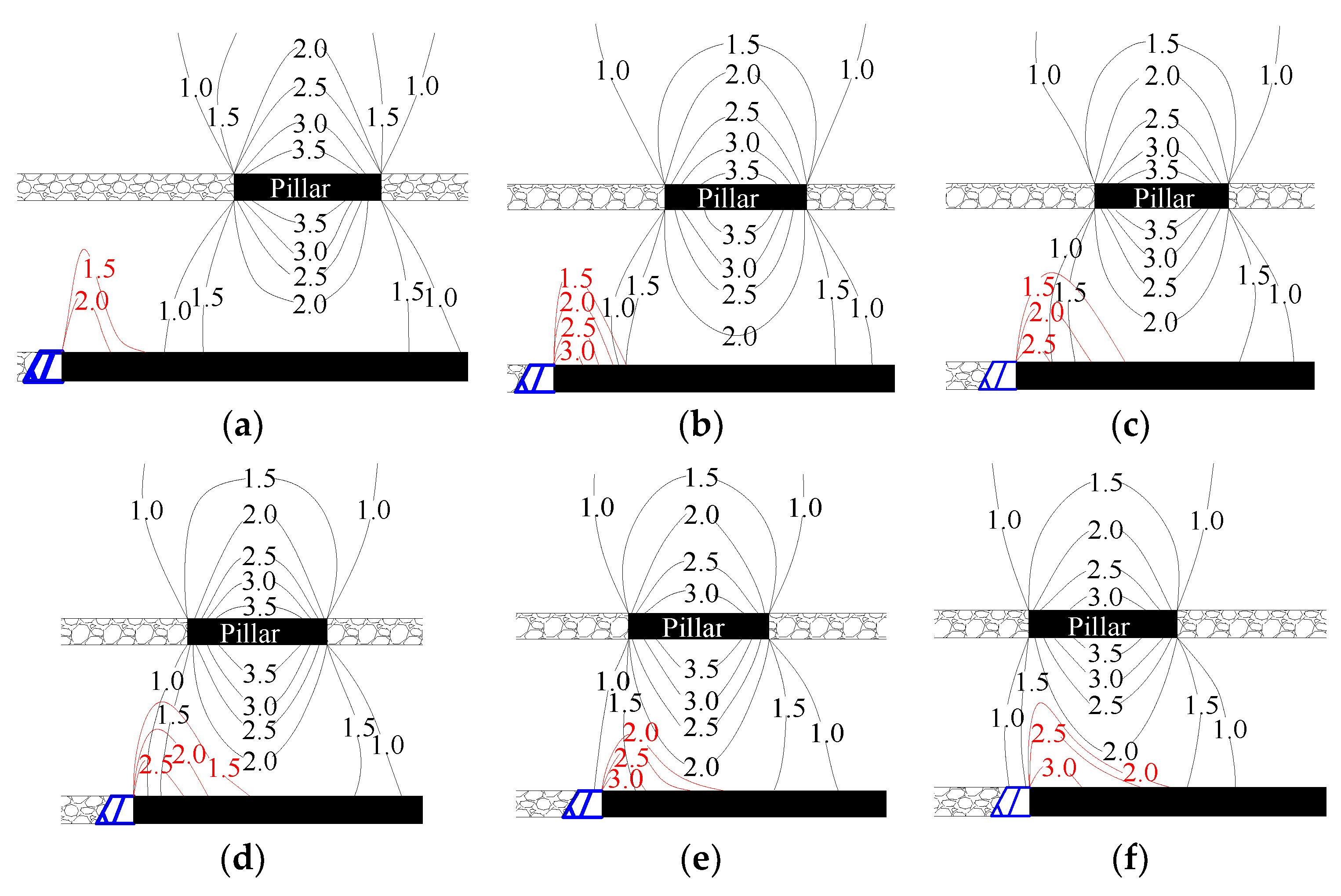
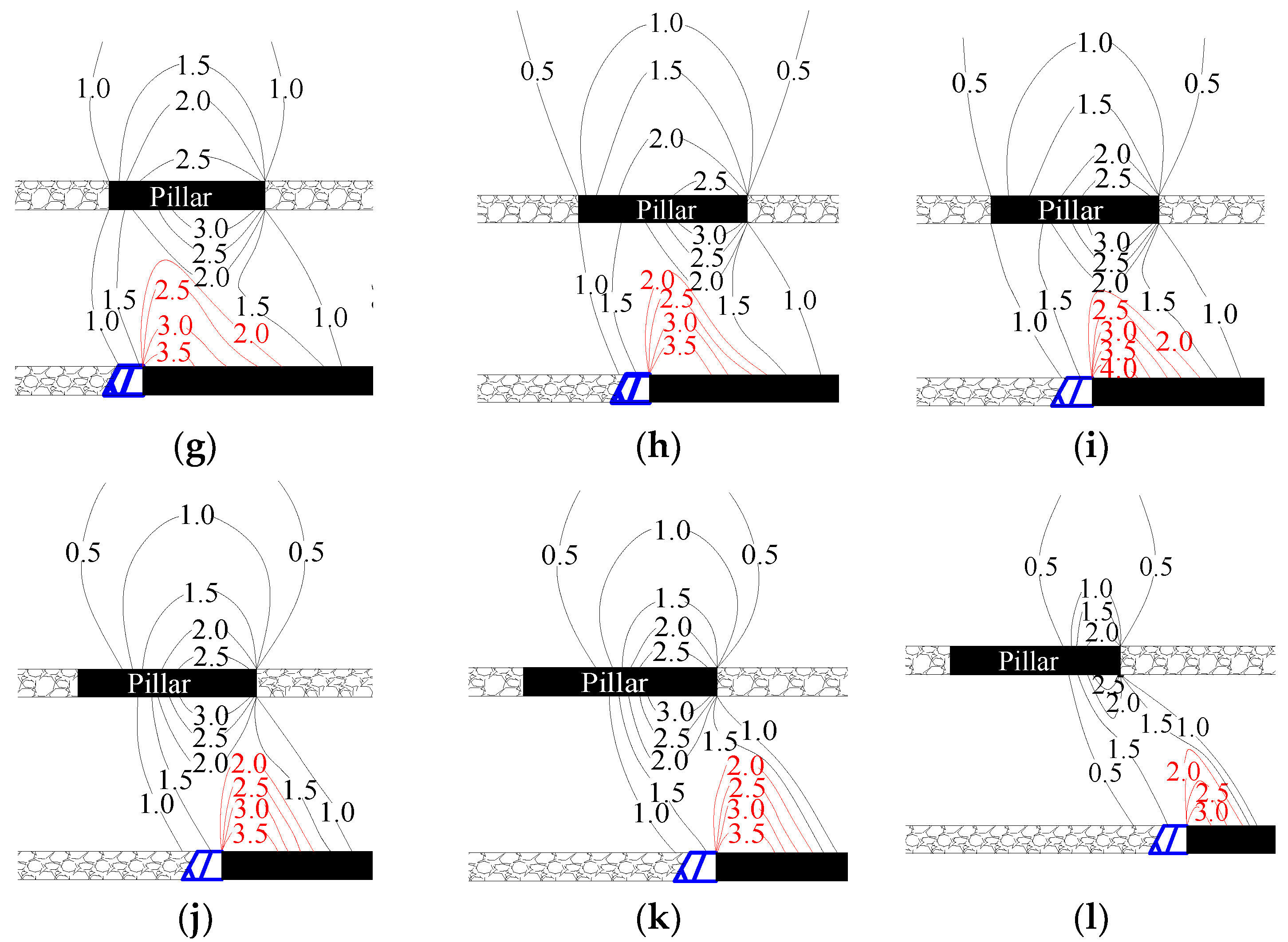
The peak of stress concentration above the pillar (PSCAP) decreases with the advance of the working face, and the PSCAP before the coal pillar is 3.5, the PSCAP after the coal pillar 10 m is 2.0, and after the coal pillar 20 m is 0.5. It shows that in the stage of coal pillar mining, when the structure of the inverted trapezoid above the coal pillar changes, the load distribution has shifted, as shown in Figure 19. Figure 19 shows the peak of stress concentration front abutment pressure is PSCFAP, the peak of stress concentration under the pillar is PSCUP, and the peak of stress concentration of WR is PSCWR.
Before the working face enters the coal pillar, the stress concentration above the pillar is symmetrically distributed, the mining has little effect on the stress of the coal pillar. When the working face enters the mining under the coal pillar, with the working face advances, the influence area of the coal pillar stress decreases, and the PSCAP gradually shifts to the outside of the coal pillar.
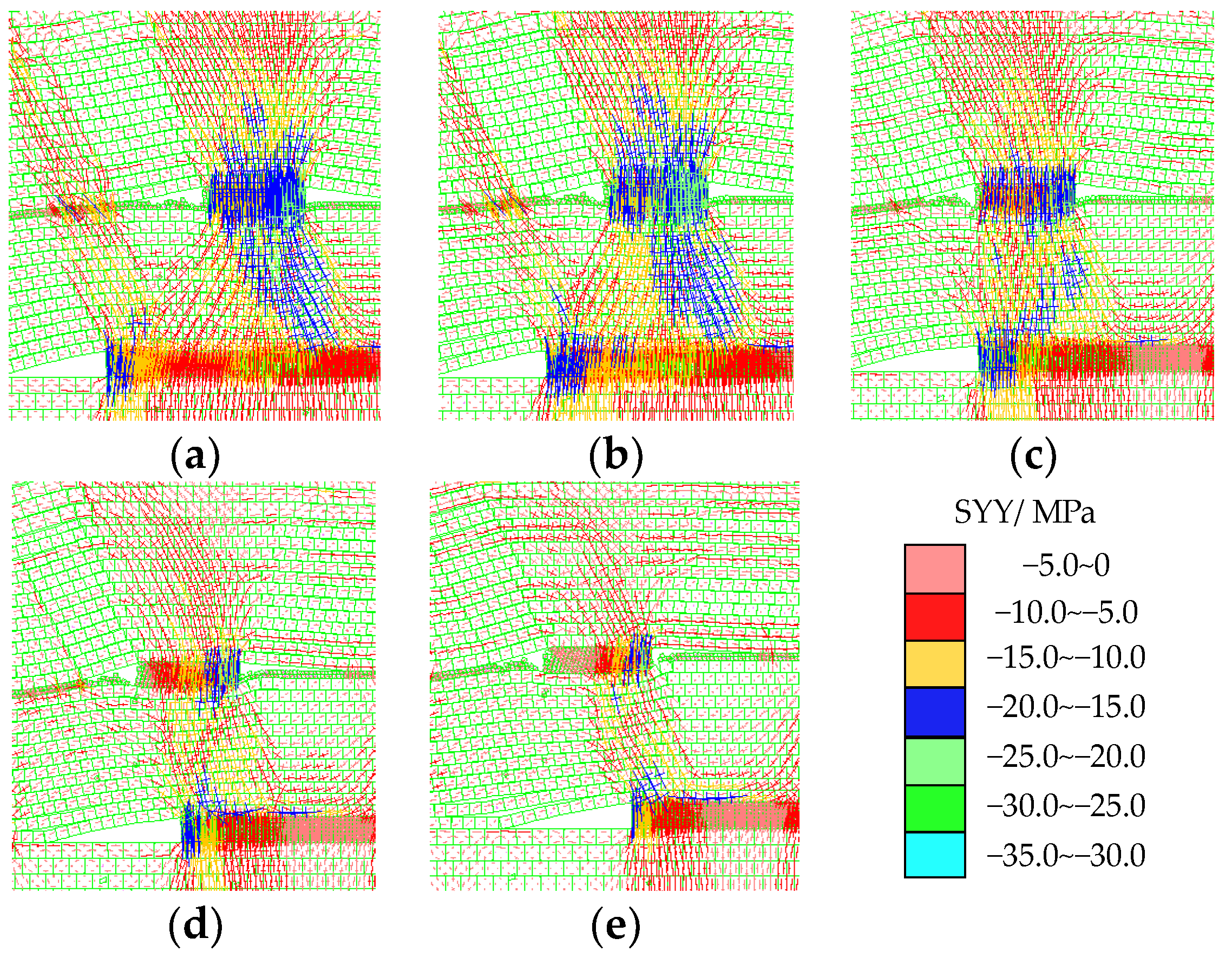
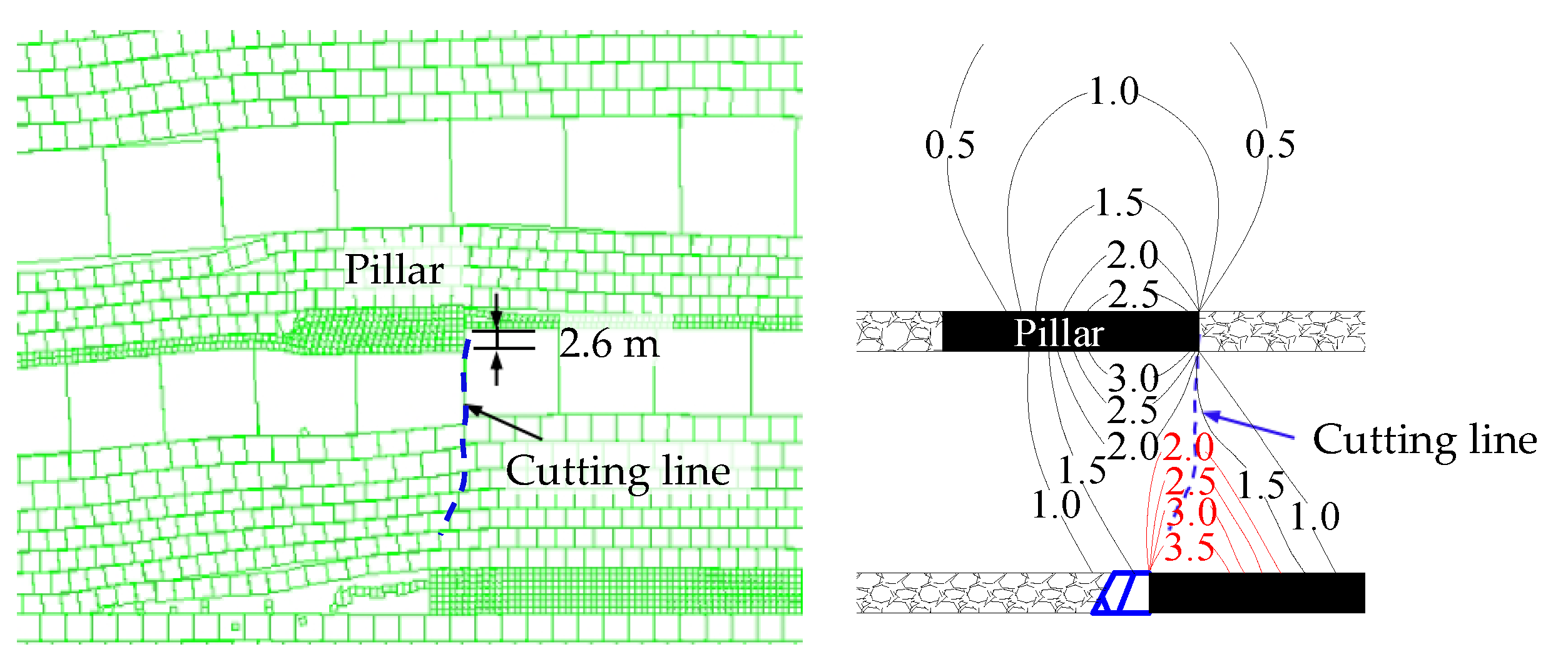
Due to the stress concentration of the inverted trapezoidal structure of the coal pillar, in the stage of passing the coal pillar, the concentrated stress is transferred to the interburden, coal rib, and support. Combined with the characteristics of the three stages and four regions obtained, when the working face is 5 m ahead of the coal pillar, the concentrated stress of the coal pillar is transferred to the boundary of the coal pillar. At this moment, the peak of the WR reaches the maximum, and the working faces is cut by the concentrated stress contour, as shown in Figure 20.

6.2. Results of Numerical Simulation
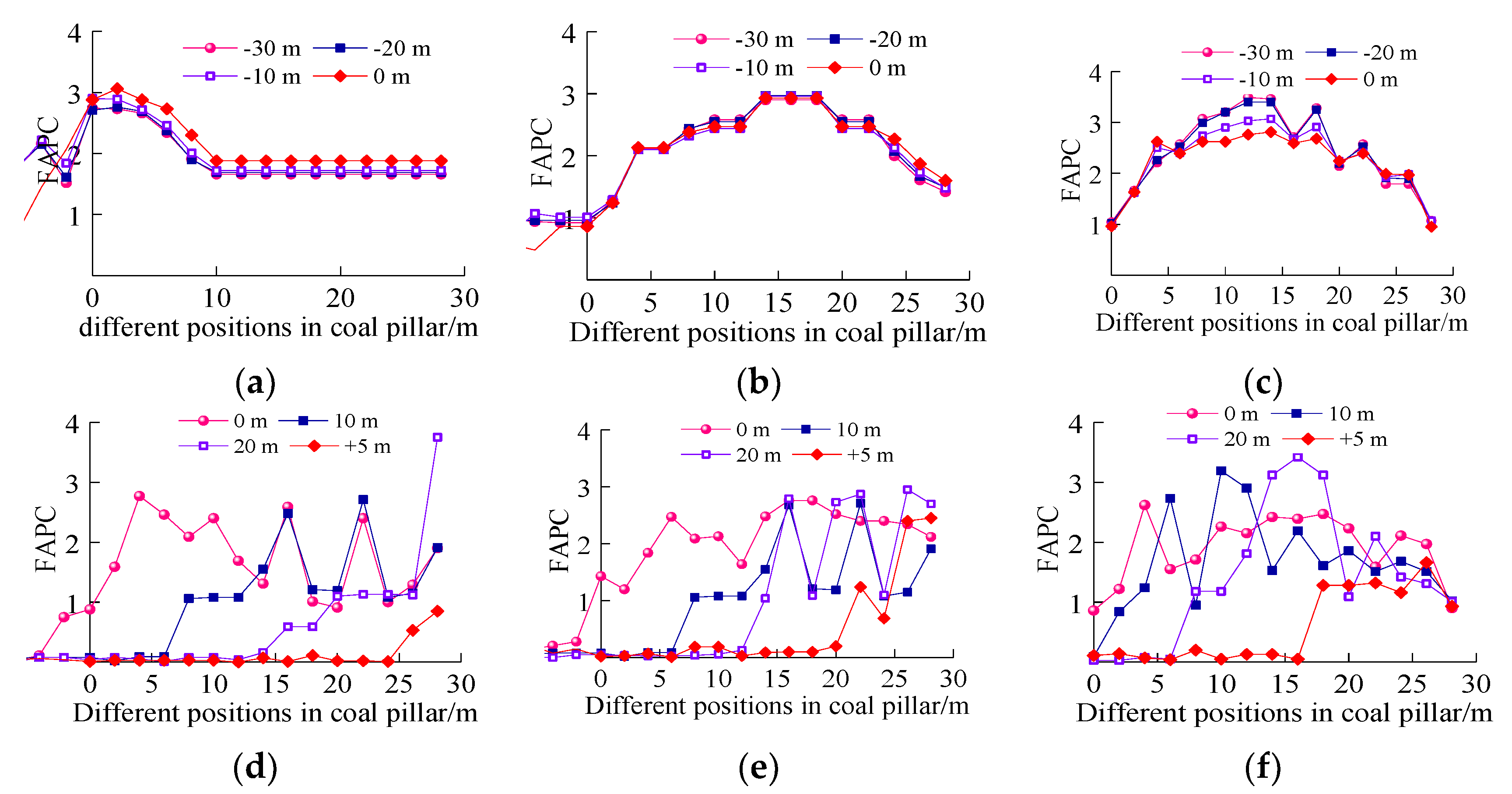
Through the numerical simulation of the pre-arranged measuring lines, the law of stress concentration variation in the lower coal seams of 6 m, 14 m, and 24 m interburden layers are analyzed, the simulation results are shown in Figure 21.
The stress concentration in the 6 m layer mainly affects the FAP, the distribution of 14 m and 24 m layers RSCC are basically symmetrical along the center line of the coal pillar.
Before the working face enters the coal pillar: with the decrease of the distance from the coal pillar boundary, the 6 m layer RSCC increases from 2.73 to 3.06, an increase of 12%; the 14 m layer RSCC remains basically unchanged; the 24 m layer RSCC is obviously reduced from 3.46 to 2.31, which is reduced by about 33%. It shows that before entering the coal pillar, mining will lead to a decrease in stress concentration in the upper layer of the interburden, and an increase in stress concentration in the lower layer.
After the working face enters the coal pillar: with the different distances of the working face entering the coal pillar, the stress concentration of the roof in different layers of the interburden fluctuates greatly, indicating that the roof stress in the interval strata is redistributed. In the working face into the coal pillar 20 m (pass the coal pillar before 5 m), 6 m, and 24 m layers of the roof stress concentration fluctuations, a wide range of pressure.

7. Conclusions

This paper uses physical simulation experimentation and numerical calculation to master the characteristics of overlying strata and the law of roof weighting in shallow buried closely multiple-seam. The zonal characteristics of mutual transformation between the roof weighting and the WR at the stage of passing the coal pillar are revealed, mainly drawing the following conclusions:
(1)
The collapse movement of the interburden is the cause of the “activation” of the collapsed roof structure in the goaf area of the upper coal seam. The simulation found that when the interburden was broken, the FAPC increased from 1.45 to 2.47, an increase of 70.3%. It shows that the load of the collapsed roof in the upper coal seam goaf will be transmitted to the lower coal seam, causing the WR and FAP to increase, and the development height and range of activated cracks in the overlying increase stepwise.
(2)
During the mining of passing the inclined coal pillar, the transfer of the concentrated stress of coal pillars to the roof structure of the working face is the main reason for the strong ground pressure. The coal pillar stress has a transformation process to the FAP, the stress of the interburden, and the WR, it is divided into three stages and four areas: the stage before entering the coal pillar, the FAP reduce—WR increase; entering the stage of the middle stage of the coal pillar, FAP increase—WR reduce, and the peak of FAP—WR rises conversion area; out the coal pillar stage, WR increase—FAP reduce.
(3)
Through numerical calculation and analysis, before entering the coal pillar, the stress contour above the coal pillar is symmetrically distributed; as the working face advances, the area affected by the coal pillar stress decreases, the peak of the coal pillar stress shifts to the outside of the coal pillar, and the peak value of the stress concentration factor above the coal pillar decreases. When the working face is 5 m away from the coal pillar, the peak of the supporting stress in front of the coal rib reaches the maximum, and the peak value of the FAP reaches the maximum. When the working face is cutting along the concentrated stress contour, it has a strong ground pressure appears on the working face.
(4)
Before entering the coal pillar, mining will lead to the reduction of the stress concentration in the higher layer of the interburden formation, and the increase of the stress concentration in the lower layer. After entering the coal pillar: the roof stress of the different layers of the interburden fluctuates greatly. As the working face enters 20 m under the coal pillar (5 m before the coal pillar), the roof stress concentration of the 6 m and 24 m layers fluctuates greatly, and the working face is expected to occur movement in a wide range.

Author Contributions

Conceptualization, Y.H. and Q.H.; methodology, Y.H. and Q.H.; software, Q.H. and Y.W.; validation, Y.H. and Q.H.; formal analysis, Q.H. and Y.W.; investigation, Y.H., Q.H. and J.D.; resources, Y.H., Q.H., and J.D.; data curation, Y.H., Y.W. and J.D.; writing—original draft preparation, Y.H. and Q.H.; writing—review and editing, Y.H. and Q.H.; visualization, Y.H. and Q.H.; project administration, Q.H. and J.D.; funding acquisition, Y.H.; Q.H. and J.D. All authors have read and agreed to the published version of the manuscript.

Funding

This research is supported by the National Natural Science Foundation of China (Nos. 52074211; 52204154), the Natural Science Basic Research Program of Shaanxi (No. 2022JM-300), and Key Laboratory Open Project Fund of Mine Geological Hazards Mechanism and Control, Ministry of Natural Resources, China (No. 2022-6).

Data Availability Statement

The data presented in this study are available on request from the corresponding author.

Acknowledgments

We thank the National Natural Science Foundation of China, the Natural Science Basic Research Program of Shaanxi and the Key Laboratory Open Project Fund of Mine Geological Hazards Mechanism and Control for its support of this study. We thank the academic editors and anonymous reviewers for their kind suggestions and valuable comments.

Conflicts of Interest

The authors declare no conflict of interest concerning the publication of this paper.

References

  1. Huang, Q.; He, Y.; Cao, J. Experimental investigation on Cracks Development Characteristics in Shallow Coal Seam Mining, China. Energies 2019, 12, 1302. [Google Scholar] [CrossRef] [Green Version]
  2. Huang, Q.; Du, J.; Chen, J.; He, Y. Coupling control on pillar stress concentration and surface cracks in shallow multi-seam mining. Int. J. Min. Sci. Technol. 2021, 31, 95–101. [Google Scholar] [CrossRef]
  3. Fiscor, S. 2020 US longwall census. Coal Age 2020, 1, 16–18. [Google Scholar]
  4. Peng, S. Longwall Mining, 3rd ed.; CRC Press: Boca Raton, FL, USA, 2019. [Google Scholar]
  5. Holla, L.; Buizen, M. The ground movement, strata fracturing and changes in permeability due to deep longwall mining. Int. J. Rock Mech. Min. Sci. Geomech. Abstr. 1991, 28, 207–217. [Google Scholar] [CrossRef]
  6. Sadasivam, S.; Thomas, H.; Zagorscak, R.; Davies, T.; Price, N. Baseline geochemical study of the Aberpergwm mining site in the South Wales Coalfield. J. Geo. Exlpor. 2019, 202, 100–112. [Google Scholar] [CrossRef]
  7. Szurgacz, D.; Brodny, J. Analysis of the influence of dynamic load on the work parameters of a powered roof support’s hydraulic leg. Sustainability 2019, 11, 2570. [Google Scholar] [CrossRef] [Green Version]
  8. Ritesh, L.D.; Murthy, V.; Kalendra, S. Semi-empirical model for predicting pot-hole depth in underground coal mining. Curr. Sci. 2018, 115, 1761–1769. [Google Scholar] [CrossRef]
  9. Maleki, H. Coal pillar mechanics of violent failure in U.S. Mines. Int. J. Min. Sci. Technol. 2017, 27, 387–392. [Google Scholar] [CrossRef]
  10. Singh, R.; Mandal, P.K.; Singh, A.K.; Kumar, R.; Maiti, J.; Ghosh, A.K. Upshot of strata movement during underground mining of a thick coal seam below hilly terrain. Int. J. Rock Mech. Min. Sci. 2008, 45, 29–46. [Google Scholar] [CrossRef]
  11. Bryan, A.; Bryan, J.; Fouche, J. Some problems of strata control and support in pillar workings. Min. Eng. 1966, 123, 238–254. [Google Scholar]
  12. Haycocks, C.; Ehgartner, B.; Karmis, M. Pillar Load Transfer Mechanisms in Multiple-Seam Mining; Society for Mining, Metallurgy, and Exploration, Inc.: Littleton, CO, USA, 1982; pp. 69–82. [Google Scholar]
  13. Poulsen, B. Coal pillar load calculation by pressure arch theory and near field extraction ratio. Int. J. Rock Mech. Min. Sci. 2010, 47, 1158–1165. [Google Scholar] [CrossRef]
  14. Singh, R.; Sheorey, P.; Singh, D. Stability of the parting between coal pillar workings in level contiguous seams. Int. J. Rock Mech. Min. Sci. 2002, 39, 9–39. [Google Scholar] [CrossRef]
  15. Guy, R.; Kent, M.; Russell, F. An assessment of coal pillar system stability criteria based on a mechanistic evaluation of the interaction between coal pillars and the overburden. Int. J. Min. Sci. Technol. 2017, 27, 9–15. [Google Scholar]
  16. Das, A.; Mandal, P.; Paul, P.; Sinha, R. Generalised analytical models for the strength of the inclined as well as the flat coal pillars using rock mass failure criterion. Rock Mech. Rock Eng. 2019, 52, 3921–3946. [Google Scholar] [CrossRef]
  17. Frith, R.; Reed, G. Limitations and potential design risks when applying empirically derived coal pillar strength equations to real-life mine stability problems. Int. J. Min. Sci. Technol. 2018, 29, 17–25. [Google Scholar] [CrossRef]
  18. Quang, P.; Zubov, V.; Duc, T. Design a reasonable width of coal pillar using a numerical model. A case study of Khe Cham basin, Vietnam. In Proceedings of the Fifth International Innovative Mining Symposium, Kemerovo, Russia, 19–21 October 2020; Volume 174, p. 01043. [Google Scholar]
  19. Yang, J. Dynamic pressure prevention and control technology of coal mining face with shallow depth and contiguous seams passing through overburden goaf and coal pillars. Coal Sci. Technol. 2015, 43, 9–13+40. [Google Scholar] [CrossRef]
  20. Rashed, G.; Mohamed, K.; Kimutis, R. A coal rib monitoring study in a room-and-pillar retreat mine. Int. J. Min. Sci. Technol. 2021, 31, 127–135. [Google Scholar] [CrossRef]
  21. Tuncay, D.; Tulu, I.; Klemetti, T. Re-analysis of abutment angle method for moderate and deep cover retreat room and pillar mines and investigation of loading mechanics using finite volume modeling. Rock Mech. Rock Eng. 2021, 54, 3447–3468. [Google Scholar] [CrossRef]
  22. Zhu, W.; Chen, L.; Zhou, Z.; Shen, B.; Xu, Y. Failure Propagation of Pillars and Roof in a Room and Pillar Mine Induced by Longwall Mining in the Lower Seam. Rock Mech. Rock Eng. 2019, 52, 1193–1209. [Google Scholar] [CrossRef]
  23. Huang, Q.; Qian, M.; Shi, P. Structural analysis of main roof stability during periodic weighting in longwall face. J. China Coal Soc. 1999, 24, 581–585. [Google Scholar]
  24. Huang, Q. Study on loading distribution law on key roof and its structure upon mining face under thick sandy horizon. J. China Univ. Min. Technol. 2005, 34, 289–293. [Google Scholar]
  25. Huang, Q. Experimental research of overburden movement and subsurface water seeping in shallow seam mining. J. Uni. Sci. Technol. Beijing 2007, 14, 483–489. [Google Scholar] [CrossRef]
  26. Cao, J.; Huang, Q. Roof structure of shallow coal seam group mining in Western China. PLoS ONE 2021, 16, e0255047. [Google Scholar] [CrossRef] [PubMed]
  27. Huang, Q.; Zhou, J.; Cao, J. Key Stratum structure and support working resistance of longwall face with large mining height in the shallow coal Seams, China. Adv. Civ. Eng. 2020, 2020, 8834403. [Google Scholar] [CrossRef]
  28. He, Y.; Huang, Q. Research on roof structure and determination of working resistance of shallow buried single key stratum based on grid-drillhole field method. Lithosphere 2022, 4, 4328618. [Google Scholar] [CrossRef]
  29. Ju, J.; Xu, J. Surface stepped subsidence related to top-coal caving longwall mining of extremely thick coal seam under shallow cover. Int. J. Rock Mech. Min. Sci. 2015, 78, 27–35. [Google Scholar] [CrossRef]
  30. Xu, J.; Zhu, W.; Wang, X.; Zhang, Z. Influencing mechanism of gully terrain on ground pressure behaviors in shallow seam longwall mining. J. China Coal Soc. 2012, 37, 179–185. [Google Scholar]
  31. Xu, J.; Zhu, W.; Ju, J. Supports crushing types in the longwall mining of shallow seams. J. China Coal Soc. 2014, 39, 1625–1634. [Google Scholar]
  32. Li, X.; Chen, S.; Wang, S. Study on in situ stress distribution law of the deep mine taking Linyi Mining area as an example. Adv. Mater. Sci. Eng. 2021, 9, 5594181. [Google Scholar] [CrossRef]
  33. Liu, H.; Zhang, B.; Li, X. Research on roof damage mechanism and control technology of gob-side entry retaining under close distance gob. Eng. Fail. Anal. 2022, 138, 106331. [Google Scholar] [CrossRef]
  34. Wang, S.; Li, X.; Qin, Q. Study on surrounding rock control and support stability of ultra-large height mining face. Energies 2022, 15, 6811. [Google Scholar] [CrossRef]
  35. Dong, H.; Zhu, W.; Hou, C.; Liu, X. Load transfer behavior during cascading pillar failure: An experimental study. Rock Mech. Rock Eng. 2022, 55, 1445–1460. [Google Scholar] [CrossRef]
  36. Chen, Z.; Zhang, L.; Yang, D.; Jiang, B. Dynamic loading effect of support while roof cutting in shallow coal seam mining. J. China Coal Soc. 2017, 42, 322–327. [Google Scholar]
  37. Yang, D.; Chen, Z.; Hong, Q.; Zang, S. Catastrophic analysis of support crushing disasters while roof cutting in shallow seam mining. J. Min. Saf. Eng. 2016, 33, 122–127+133. [Google Scholar]
  38. Zhu, W.B.; Xu, J.M.; Li, Y.C. Mechanism of the dynamic pressure caused by the instability of upper chamber coal pillars in Shendong coalfield, China. Geosci. J. 2017, 21, 729–741. [Google Scholar] [CrossRef]
  39. Feng, J.; Zhou, Y.; Zhang, K.; Xu, Y.; Li, H. Fracture characteristics of thick key stratum and calculation of shield work load under multiple coal seam mining gobs with shallow depth. J. Min. Saf. Eng. 2018, 35, 332–338. [Google Scholar]
  40. Yu, D.; Yi, X.; Liang, Z.; Lou, J.; Zhu, W. Research on Strong Ground Pressure of Multiple-Seam Caused by Remnant Room Pillars Undermining in Shallow Seams. Energies 2021, 14, 5221. [Google Scholar] [CrossRef]
Figure 1. Plan view of the 22410 working face.
Minerals 13 00118 g001
Figure 2. Histogram of No.b280 borehole.
Minerals 13 00118 g002
Figure 3. Schematic diagram of physical simulation experiment.
Minerals 13 00118 g003
Figure 4. Stress sensors and instruments for the experiment: (a) Wireless stress sensor. (b) Ultra-thin pressure sensor. (c) Leica total station. (d) HD camera.
Minerals 13 00118 g004
Figure 5. Law of roof caving during periodic weighting: (a) FPW1. (b) FPW4. (c) SPW6. (d) Law of the WR during the period weighting.
Minerals 13 00118 g005
Figure 6. Stress concentration coefficient law of floor and 24 m layer after mining of 1−2 coal seam.
Minerals 13 00118 g006
Figure 7. Law of weighting during the interburden unbroken: (a) FW. (b) FPW1.
Minerals 13 00118 g007
Figure 8. Law of weighting during interburden broken: (a) SPW2. (b) TPW3.
Minerals 13 00118 g008
Figure 9. Law of period weighting under the goaf: (a) FPW4. (b) FPW5.
Minerals 13 00118 g009
Figure 10. Law of WR in periodic weighting.
Minerals 13 00118 g010
Figure 11. Law of FAPC and 24 m layer RSCC: (a) FAPC and 24 m layer RSCC of interburden unbroken. (b) FAPC and 24 m layer RSCC of interburden broken.
Minerals 13 00118 g011
Figure 12. Height of overburden fractured zone after two coal seams mining.
Minerals 13 00118 g012
Figure 13. Strong ground pressure passing the coal pillar mining: (a) Normal period weighting under the coal pillar. (b) Interburden is cutting, the working face support is crushing.
Minerals 13 00118 g013
Figure 14. Subsidence of coal pillar and upper inverted trapezoidal structure after periodic weighting.
Minerals 13 00118 g014
Figure 15. By passing the coal pillar, the change of FAPC and 24 m layer RSCC: (a) FAPC before coal pillar. (b) 24 m layer RSCC before coal pillar. (c) FAPC enter the coal pillar. (d) 24 m layer RSCC enter the coal pillar. (e) FAPC out coal pillar. (f) 24 m layer RSCC out coal pillar.
Minerals 13 00118 g015aMinerals 13 00118 g015b
Figure 16. Evolution of FAP and WR by passing the coal pillar.
Minerals 13 00118 g016
Figure 17. Variation of interburden and pillar stress and FAP by passing coal pillar: (a) 25 m before the coal pillar (−25 m), (b) 15 m before the coal pillar (−15 m), (c) 0 m into the coal pillar (0 m), (d) 10 m into the coal pillar (10 m), and (e) 20 m into the coal pillar (20 m).
Minerals 13 00118 g017
Figure 18. Variation of interburden and pillar stress and FAP by passing coal pillar: (a) 30 m before coal pillar, (b) 20 m before the coal pillar, (c) 15 m before the coal pillar, (d) 10 m before the coal pillar, (e) 5 m before the coal pillar, (f) 0 m into the coal pillar, (g) 15 m into the coal pillar, (h) 10 m into the coal pillar, (i) 15 m into the coal pillar, (j) 20 m into the coal pillar, (k) 25 m into the coal pillar, and (l) 5 m out the coal pillar.
Minerals 13 00118 g018aMinerals 13 00118 g018b
Figure 19. The mutual transformation between the WR, FAPC, and coal pillar during the passing of the pillar.
Minerals 13 00118 g019
Figure 20. Interburden and coal pillar vertical cutting occurred by the working face strong weighing.
Minerals 13 00118 g020
Figure 21. Distribution characteristic curves of the different layers RSCC of working face passing the coal pillar: (a) 6 m layer RSCC before the pillar, (b) 14 m layer RSCC before the pillar, (c) 24 m layer RSCC before the pillar, (d) 6 m layer RSCC enter the pillar, (e) 14 m layer RSCC enter the pillar, and (f) 24 m layer RSCC enter the pillar. (Note: “−” represents before the coal pillar, “+” represents after the coal pillar).
Minerals 13 00118 g021
Table 1. Material ratio of physical simulation experiment.
LithologyGeological Thickness
/m
Model Thickness
/cm
Model Cumulative
Thickness/cm
ProportionConsumables/kg/cm
River SandGypsumWhite Powder
Drift sand22.3316151.59198.640.100.86
Sandy mudstone15.610.5135.59288.640.190.77
Mudstone4.2631259378.640.290.67
Sandy mudstone28.0618.51229288.640.190.77
Fine-grainednsandstone4.873.5103.58378.530.320.75
Sandy mudstone5.413.51009288.640.190.77
Fine-grained sandstone6.374.596.58378.530.320.75
Sandy mudstone9.976.5929288.640.190.77
Mudstone1.6185.59378.640.290.67
Sandy mudstone11.777.584.59288.640.190.77
Mudstone4.323779378.640.290.67
Sandy mudstone30.5920.5749288.640.190.77
Fine-grained sandstone8.325.553.58378.530.320.75
Coarse-grained sandstone15.2810.5488288.530.210.85
Sandy mudstone7.044.537.59288.640.190.77
1−2 coal seam6.844.53320:1:5:205.090.251.27
Fine-grained sandstone5.92428.58378.530.320.75
Coarse-grained sandstone11.467.524.58288.530.210.85
Sandy mudstone6.154179288.640.190.77
Siltstone2.762139378.640.290.67
Sandy mudstone4.33119288.640.190.77
Mudstone2.061.589378.640.290.67
Sandy mudstone21.56.59288.640.190.77
2−2 coal seam7.315520:1:5:205.090.251.27
Disclaimer/Publisher’s Note: The statements, opinions and data contained in all publications are solely those of the individual author(s) and contributor(s) and not of MDPI and/or the editor(s). MDPI and/or the editor(s) disclaim responsibility for any injury to people or property resulting from any ideas, methods, instructions or products referred to in the content.

