1. Introduction
Although coal resource reserves are relatively abundant in China, most of them are developed in deep strata, where the risks of high in situ stress, high temperature, gas explosion and outburst, and water inrush impede the safe operation and production of a coal mine [
1,
2]. Especially, underground dynamic phenomena such as rock bursts or coal bounces as well as limestone water hazards with high pressure have commonly occurred in recent decades [
3,
4,
5]. Therefore, shallow buried coal seams underlying the loose strata have become the preferable choice for coal mines.
Despite mitigating the mining geological risks compared with those of deep mining to some extent, some issues need to be discussed and addressed before excavation. Given the influence of loose aquifer bodies on the shallow coal seams, the deformation and fracture development of overburdened strata during the process of mining has been expounded to avoid the occurrence of water and sand outburst accidents [
6]. Additionally, the confined or phreatic water table constantly decreases due to mine drainage resulting in increasing effective stress in the rock and soil, which deteriorates the ecological environment, such as damaged house structures resulting from uneven surface subsidence and dead vegetation, as well as deserted land attributed to a lack of water.
Therefore, a thorough understanding of the deformation and migration patterns of overburdened strata induced by mining is of great significance to ecology protection and safety mining. For this purpose, domestic and foreign researchers give more attention to figuring out the mechanism, monitoring, and prediction of overlying strata deformation in which some achievements have been attained. Theoretically, the Hoek–Brown failure criterion on the geological strength index (GSI) is first introduced to determine the mechanical parameters of rock mass [
7,
8,
9], and then the concept of the key strata theory is proposed to locate overlying strata controlling the deformation, breakage, and migration of rock mass [
10,
11], which are subdivided into the primary key stratum and the first key stratum with stiff and thick rock in further studies. With the advancement of technology and the promotion of artificial intelligence, monitoring methods and instruments are gradually maturing. For instance, numerical simulations based on UDEC, FLAC, 3DEC, etc. are commonly applied to reproduce the deformation and failure process of overburdened strata during mining periods [
2,
3,
5,
12,
13,
14,
15,
16]. Geophysical exploration (electricity method, resistivity method, electromagnetic method, etc.), and drilling are implemented as an in-site field measurement method [
17,
18,
19,
20]. Moreover, distributed fiber optic sensing (DOFS) technology with the virtue capacity of portable installation, low environmental requirements, and real-time online monitoring becomes an effective strategy to measure the deformation and strain distribution of overburdened strata [
21,
22,
23]. Approximately reflecting the actual geological condition of a targeted area, similar material modeling embedded in DOFS can analyze the deformation characteristic of overburdened strata from the small-scale perspective in the laboratory [
24,
25,
26,
27]. Some scholars put forward the multi-method combination of space–sky–surface (3S) integrated monitoring to reveal the spatial-temporal laws of rock strata movement, surface deformation, and subsidence during mining periods [
28].
Most previous works mainly concentrate on the deformation of overburdened strata under deep mining conditions using one or two methods, whereas rare systematic research has been dedicated to the deformation of overburdened strata under huge thicker loose layers. Such geological conditions in the No.1 mining area of the Lilou coal mine are studied to analyze the deformation and migration of overburdened strata using theoretical analysis and experimental and in situ detecting measures in the study. Accordingly, the outline structure of this paper is designed as follows.
Section 2 introduces the engineering profile of the study area.
Section 3 presents the methodology and essential data for the study. The results of the integrated methods are illustrated in
Section 4.
Section 5 discusses comparisons and limitations of the experiment, the perspective of future research, and so on. General conclusions are provided in
Section 6. The study results are of significance in controlling and managing the roof strata during shallow coal seams mining.
2. Engineering Background
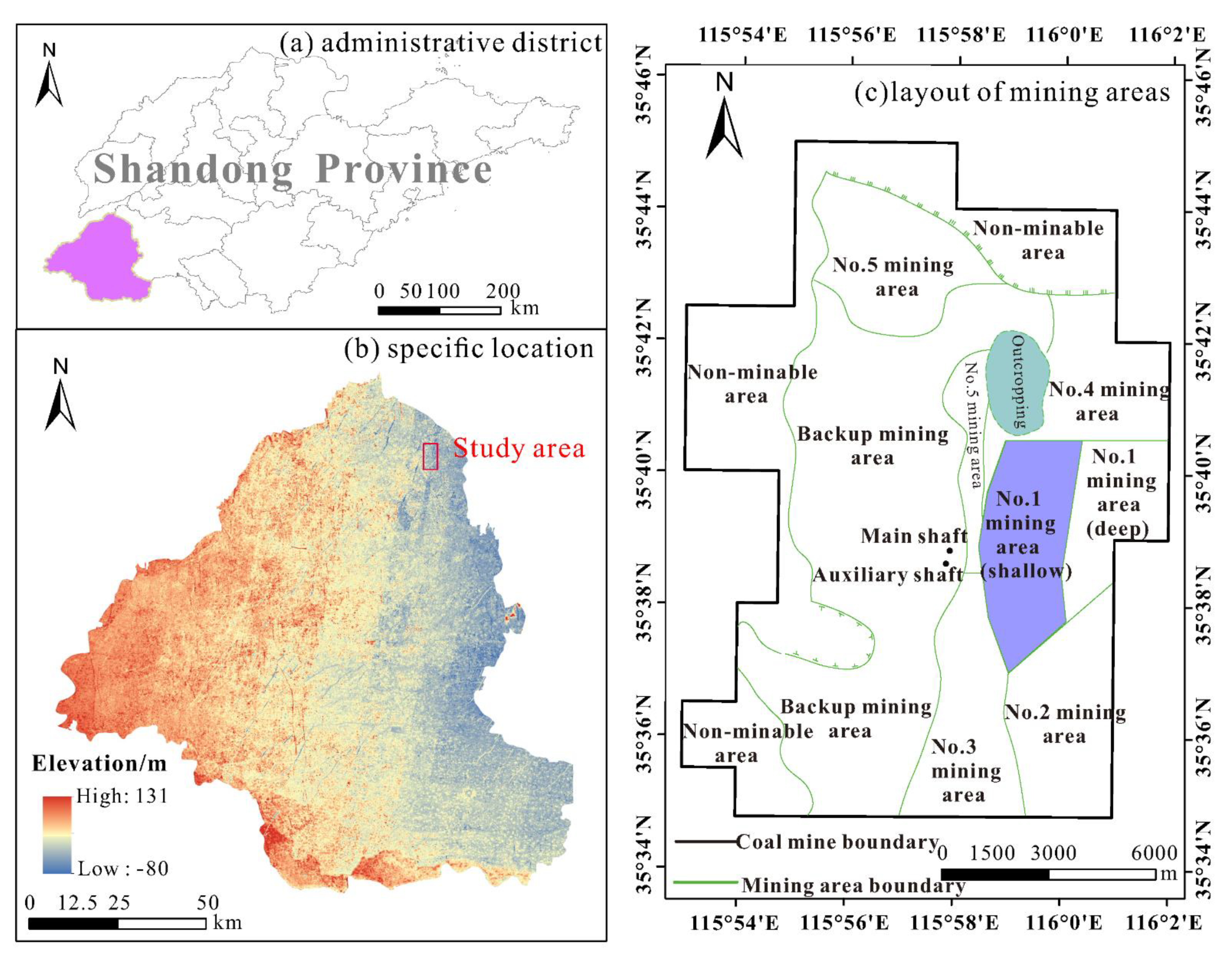
The geological location of the Lilou coal mine is located in the northeast of Heze city, Shandong Province, which belongs to the Juye mine area, presented in
Figure 1a,b. The size of the area is approximately 17 km in length and 12 km in width. The geographic coordinate of the mine is the east longitude ranging from 115°52′57″ to 116°01′57″, and the north latitude ranging from 35°34′46″ to 35°45′01″. The annual production capacity is 2.4 million tons, and the mine life span is 111.7 years.
In the western and northern zones, Non-minable zones covering almost one-third of the mine are attributed to stratigraphic sedimentary discontinuities. According to the preliminary planning and designs, six mining areas (No.1~No.5 mining area, and backup mining area) are distributed in the mine. Adopting longwall mining with top coal caving, the first mining area located in the east of the mine is the No.1 mining area, which is subclassified into the shallow and deep areas with the main mining 3# coal seam currently as shown in
Figure 1c. The shallow region serves as the focus of this study, including the 1300, 1301, and 1302 coalfaces, etc.
Due to the strata subdivision of the coal mine belonging to the Luxi stratigraphic division, the study area is mostly covered by Cenozoic loose layers with a thickness of 472.8 m–591.3 m. The unconsolidated layers consisting of a huge thicker loose soil and rock mass contribute to distinct geological conditions which affect the deformation and migration of overburdened strata induced by mining shallow coal seams, especially in the shallow part of the No.1 mining area as a coal production source for the moment.
3. Materials and Methods
To further reveal the deformation patterns of overburdened strata, the primary engineering geological conditions of the study area are mastered through comprehensive geological explorations, and the mechanical properties of the rock and coal are quantitated through in situ measurements and indoor testing. The stratification and mechanical parameters of the roof strata are shown in
Table 1. On the foundation of previous preparations and the relevant literature review, theoretical analysis, numerical and physical similar simulations, and in situ field measurement are sequentially applied to form a comprehensive analysis of the deformation and migration of the roof strata by comparison and verification in the present study.
Through the theoretical analysis of overburdened strata failure, instinctive characteristics and patterns of rock deformation are preliminarily understood, serving as the technical basis for further simulations and field measurements. Considering the advantages of 3DEC software with a discrete element code, the discontinuous and large deformation failure of rock mass by mining can be effectively dealt with. A simulation test of similar materials with a low capital cost is commonly accepted as a means of simulating underground mining activities, while the on-site monitoring of the coalface or the roadway is the most direct and reliable method, which accurately determines the distribution scale of the damaged strata.
4. Results
4.1. Mechanical Model Analysis
After sorting the prior analysis of the mechanical behavior characteristics of overburdened strata affected by mining [
4,
29,
30,
31], the mechanical analysis of overburdened rock under mining with a stable fixed support in three edges and an unstable support in one edge is employed. Based on the load-bearing mechanical model of the plate structure under the elastic foundation, the model establishment is presented in
Figure 2. The mechanical model premising the below assumptions is proposed: (i) The overburdened stratum is considered a continuous, uniform, and isotropic elastic rectangular thin plate structure; (ii) The gravitational stress effect of the loose layers on the overburdened strata is given as an equivalent uniform load
p =
rh; (iii) Conforming to the mechanical behavior of Winkler elastic foundation, the bottom stratum with a reverse bearing force is regarded as the continuous elastic foundation; (iv) The stable fixed support is determined by the movement angle of the overburdened stratum, and the unstable fixed support is above the center of the coal pillar.
The equilibrium differential formula of a model under an elastic foundation is:
where
w and
D are the bending deflection and stiffness of overburdened strata, respectively;
p =
rh is the upper load of overburdened strata,
r is the dead weight of rock and soil mass, and
h is the buried depth;
n is the elastic foundation coefficient of underlying coal and rock mass;
n0 is the weakening effect coefficient after mining. Moreover, boundary conditions satisfy the following expressions:
Only if the coal pillar withstanding high stress has sufficient size can the overburdened strata keep the stable situation at the fixed edge, namely wm = 0. Nevertheless, the bending deflection wm ≠ 0 serves as the unstable support edge.
To facilitate the model analysis, the bending deflection of the plate structure with three stable fixed support edges and one unstable support edge is expressed as:
where
Q and
k are uncertain coefficients.
The energy principle and the variational method are applied to solve the problem [
32], and the following expression could be known as Formula (4).
Q and
w could be solved according to Formulas (3) and (4).
On the right equation, is the influence of overburdened strata load on the upper boundary, is the reverse reaction of the elastic foundation, and is the weakening effect of the elastic foundation caused by mining.
The bending deflection of the plate structure
w is calculated as the below result.
When the stope is fully excavated as per previous designs, the subsidence deformation of overburdened strata will reach the maximum value, and then keep stable. Assuming the maximum subsidence of overburdened strata (
wmax) occurs at the point of
x = a/2,
y = 0 in combination with the unstable fixed support edge condition, the final function expression of bending deflection
w is determined.
In Equation (6), .
The maximum stress equation of overburdened strata is solved by mechanical theory. The maximum principal stress (
) at the center of the stable support edge is taken. When
is greater than the limit strength of overburdened strata ([
]), they will be deformative and fractured. The occurred condition is that:
Namely, along the stope strike;
along the stope inclination.
4.2. Numerical Analysis
4.2.1. Model Establishment
Based on the systematic analysis of the actual mining geological conditions and the comprehensive geological exploration data in the mining area, the simplified modeling of overburdened strata deformation and failure is established using 3DEC software based on discrete element code. The advantages of this tool are to analyze the discontinuous deformation and failure of rock strata due to the anisotropy and structural plane. The periodic excavation is carried out to study the movement and failure patterns of overburdened strata. The specific modeling schemes are as follows: (i) the coalface is mined along the inclined direction of a coal seam, and the inclination dip of the coal seam is around 8°, which is treated as a flat seam. Therefore, the modeling could be simplified as near-horizontal; (ii) the strike length of the coalface is 400 m, the inclination length is 150 m, and the mining height is 7.0 m. To mitigate the effect of mining on the boundary, the setup entry and stopping line extend 300 m along the strike, respectively, as per the front and rear boundaries of the model. The model is 1000 m × 300 m × 130 m (length × width × height) in size, and approximately generates 96,500 elements of varying sizes covering a range of 5 m–60 m.
4.2.2. Boundary Conditions
As illustrated in
Figure 3, the restricted displacement is used in the model boundary. The horizontal constraint is forced around the model boundary, keeping the zero displacements of the horizontal direction. The bottom plane is fixed by setting the zero displacements of the horizontal and vertical directions, while the top plane is a free surface, and the load of the top boundary is the gravitational stress from the above loose layers. The average buried depth of the loose layers is 480 m, and the equivalent stress is set to 10 MPa. The Mohr–Coulomb elastic–plastic constitutive model is selected.
4.2.3. Numerical Simulation Results
The setup entry of the coalface is designed at 300 m away from the boundary. The simulated step length of the excavation is set to 10 m, and the accumulated excavation is eventually finished after 40 cycles. With the excavation of the coal seam, the initial stress balance of the rock mass is damaged and the balance stress system around the stope is redistributed as shown in
Figure 4. When the excavation advances to 100 m, the stress of the roof rock is obviously reduced due to the roof deformation and collapse, and the affected zone is called the pressure relief zone. The maximum principal stress concentration appears in front of the coalface head and setup entry. As the mining continues, the scale of the roof pressure relief zone gradually expands, but the location of the stress concentration zone, which is the same as that of the previous excavation, remains relatively unchanged. The scale of the low-stress zone above the coalface becomes larger in
Figure 4 as the coalface advances between 300 m and 400 m. However, the fracture height does not significantly change yet, indicating that the fracture development remains stable.
The immediate roof collapses and piles up in the goaf after excavation, and the falling rock remains in the compressive state, while the upper and lower fracture zones are in the compression and tension states. Generally, the tensile failure zone, tensile fracture zone, shear failure zone, and unaffected zone develop from bottom to top. Therefore, the conventional two-belt height in the vertical profile could be determined by the distribution of the plastic zone in the numerical simulation.
During the advance of mining, the fractured zone develops into a regular saddle shape. When the coalface advances between 100 m and 200 m, the caved zone initially occurs and then the fractured zone gradually develops. The development height of the caved zone and the fractured zone tends to be stable at 300 m, as shown in
Figure 5, and their stable development heights are 32 m and 95 m, respectively.
The displacement of overburdened strata above the immediate roof in the vertical direction usually demonstrates hysteresis in contrast to the immediate roof falling with mining. However, the collapse of the immediate roof initially appears due to its gravity and the stress of the surrounding rocks. The overlying strata would move in the direction of the open face generated by excavation, and the upper rock mass would crush the lower rock mass, so the vertical displacement of the rock mass would gradually increase. From the vertical displacement cloud diagram, as represented in
Figure 6, the obvious displacement zonation and phases are developed well, demonstrating that the closer stratum is to the goaf, the greater the displacement of the stratum is.
4.3. Similar Material Simulation Analysis
4.3.1. Model Design and Materials for Simulation
A similar simulation abides by the similarity of geometry, motion, and boundary condition as well as the proportion of corresponding physical parameters. The ratio of geometric similarity is 1:200. A two-dimensional plane similar model test base with a size of 3.0 m × 0.3 m × 1.6 m (length × width × height) is designed. The external load comes from the automatic hydraulic system of the model. The model construction is shown in
Figure 7. The setup entry is located 0.4 m away from the left boundary of the prototype model.
In this experiment, natural river sand with a particle size of 0.15 mm–0.5 mm is used as the aggregate material, calcium carbonate and gypsum are selected as the simulated materials that represent cementing materials, and mica powder (sheet) is treated as a stratified material. By changing the composition proportions between aggregate and cementing materials, different rock formations are simulated. Similar materials are selected as shown in
Figure 8.
4.3.2. Deformation Characteristic of Overburdened Strata
The coal seam is excavated at 0.05 m each time, and a mining interval of six hours is implemented. The total length of the simulated mining is 2.2 m which means the actual mining length is 440 m. The simulated test could well reconstruct the deformation and failure of overburdened strata.
When 40 m of the coalface was exploited, the immediate roof began to cave, the upper basic roof with hard rock developed local cracks, and the pressure step distance was determined by about 30 m. When the coalface was excavated to 60 m in
Figure 9a, the immediate roof and partial basic roof caved fully owing to the large-scale suspended roof, while the cracks of the upper basic roof and above did not develop obviously. When mining was simulated to 90 m in
Figure 9b, the strength of the immediate roof reached the limit span and continued to collapse, but the overlying strata were not significantly damaged and the height of mining-induced fractures in overlying rocks was not increased. When the simulated mining advanced to 110 m in
Figure 9c, the basic roof reached the periodic fracture limit and fractures occurred. The height of the mining-induced fractures continually increased to about 18 m above the coalface roof, and vertical fractures were generated in the direction of 50° above the setup entry front when the coalface was mined to 140 m in
Figure 9d. The roof of the coalface caved periodically with continuous mining, and the height of the water-conducting fracture zone increased significantly in the simulated mining of 170 m as shown in
Figure 9e. After that, uneven subsidence occurred among the overlying rocks in
Figure 9f.
When 240 m of the coalface was mined as shown in
Figure 9g, the uneven subsidence layer developed at the top of the caved zone. The fracture height was about 56 m away from the roof, and the upper strata were not damaged temporarily. The length and width of the fractures gradually increased with the advance of the coalface.
Until the coalface was mined to 280 m as shown in
Figure 9i, along with the periodic collapse of the lower strata, the strength of the separated fractures gradually increased to the limit strength, and then the strata began to collapse. The upper hard strata had experienced integral tensile failure. After collapse, the fractures rapidly developed upward to about 101.4 m above the coalface.
Periodic fractures occurred in overlying strata after mining 280 m, but mining-induced fractures rarely continued to develop upward. The separation layer began to develop and then disappeared from 350 m to 420 m as displayed in
Figure 9j,k. In the early formation stage of the separation layer, the bending deformation of the upper strata was not obvious, so the separation layer could be preserved. However, the overlying strata underwent a bending deformation process, resulting in the compression of the separation space with continuous excavation. After the coalface was mined to 420 m as represented in
Figure 9l, the final mining-induced fractures developed within 102 m above the coalface. The development of the bending deformation zone also tended to be stable.
4.4. In Situ Field Measurement
Due to the resistivity of rock increasing with its failure magnitude, the deformation and failure of the overburdened strata lead to a change in the electrical resistance. Generally, the resistivity shows a relatively lower value in the bending deformation zone compared with the collapse zone, and the resistivity of the strata in the fractured zone may change greatly. Two lift boreholes, where multiple electrodes were installed, were drilled into the chamber of the 1302 haulage gateway to monitor the dynamic change in the resistivity of the overlying strata during mining as shown in
Figure 10.
According to the comparative analysis of the apparent resistivity profile, the rock mass deformation and failure in the continuous mining monitoring area of the coalface were relatively obvious, and the changes could be divided into four processes.
Process I: The deformation and migration of the overburdened strata were not obvious in the monitoring area during mining when the distance between the mining face and the location of drillings was more than 99.6 m. The overall overburden was relatively stable, demonstrating low resistivity within the scope of monitoring in
Figure 11a.
Process II: The initial stages of deformation and fracture development began to develop once the coalface advanced to a certain position between 99.6 m and 70.8 m away from the orifice. The deformation mainly occurred in soft rock or sandstone strata along with relatively developed primary fractures.
Figure 11b shows the resistivity change in the cross-section when the coalface was mined to 70.8 m.
Process III: The rock mass in the monitoring area had undergone great deformation and displacement in the process of mining to 60 m. The structure of the rock mass had been altered, a large range of fracture zone had been generated, and the local bottom rock stratum had begun to fall. The local area of the goaf roof showed low resistivity characteristics, and the resistivity of the rock in most areas was relatively higher in
Figure 11c.
Process Ⅳ: Most of the overburdened strata were suspended above the goaf in this process. The rock mass was subjected to the highly concentrated stress, and thus the damaging effect on the overburdened strata accelerated the development of the fractures, causing immediate roof caving and deformation and the migration of the basic roof judged from the high resistivity of the monitoring area in
Figure 11d.
5. Discussion
From the perspective of strata deformation mechanics, the critical conditions of strata movement and failure are analyzed based on the thin plate structure model under an elastic foundation. The maximum principal stress is affected by the thin plate structure’s size and the coal pillars’ maximum bending deflection. If it exceeds the ultimate strength the overburdened strata can bear, they will be deformed and destroyed.
Analysis of the numerical simulation shows that the deformation and failure of overburdened strata occur periodically under the influence of mining, demonstrated by the overburdened strata located on the front and rear of the goaf migrating to the central part. The evident compression deformation of the overburdened strata in the center of the goaf is represented, and the deformation distribution is approximately symmetric. The predicted height of the water-conducting fractured zone is 95 m after full mining, with a ratio of fractured and mining height of 14.4:1.0.
The overburden fracture develops gradually upward with the stope advancement until approximately 280 m in physical similar simulation. After that, the height at which the fracture develops is essentially stable. The separation layer is developed in the overburdened strata but closed due to the formation of the upper bending deformation zone in the process. After the overburden deformation becomes stable, the heights of the caved zone and the fractured zone are about 29 m and 102 m, respectively. That is to say, the ratio of the caving and the mining height, as well as the ratio of the fractured and the mining height are about 4.4:1.0 and 15.5:1.0.
In the physical similar experiment, stable subsidence deformations were captured by a high-resolution digital camera during the entire mining process, and the extraction of subsidence data in each layer was completed. The monitored strata above the coalface are clarified into nine layers which are designed as layer 1~layer 9 from down to up in the model.
Figure 12 presents the subsidence curve of the overlying rock. It is concluded that the subsidence deformation is significant in layer 5 and below, forming a caved zone and a fractured zone, while the subsidence deformation is almost identical in the bending deformation zone above layer 5, where no vertical fracture develops. Meanwhile, the maximum subsidence of the overburdened strata exists above the center of the goaf, and the deformative rocks on either side are inclined to some extent towards the center.
The overburden deformation and migration obtained by the two simulation methods are essentially identical, but there are some deviations compared to in situ field measurement. According to in situ field monitoring, the overburdened strata failure roughly goes through four stages, indicating that the overburden deformation was a progressive development process. Based on the actual detection of the 1302 coalface in the No.1 mining area, the maximum height of the caving and fractured zones are 20 m and 67 m, respectively, and the corresponding ratio of the caved and mining height, as well as the ratio of the fractured and mining heights are 3.0:1.0 and 10.2:1.0. Therefore, the estimated values are relatively lower than those of two simulations. The reasons may be that there is relatively more mica in the model for stratification, slight differences between the desired mining speed and the actual mining speed due to some uncertainties such as the stope across faults or the maintenance of fully mechanized mining machinery, and other adverse conditions. For the sake of safety, the ratio of the fractured and mining height (14.4:1.0) in the numerical simulation is determined as a reference value for mine production.
The study of overburdened strata deformation caused by mining has attracted more attention from researchers throughout the world. The discussions mainly center on the development characteristics of water-conducting fractures due to mining deep coal seams, and the separation water flows into the coalface or roadway through a water-conducting channel. However, relatively little research on overburdened strata failure caused by mining shallow coal seams under thicker unconsolidated layers is carried out, lacking comparative validation. Furthermore, the influence of overburdened strata structures and the water pressure of loose sandy layers on the development patterns and scale of overburdened strata deformation are worthy of further study through new technical detections with higher accuracy and lower cost.
6. Conclusions
Based on the theoretical analysis, numerical and physical similar simulation tests, and in situ measurement, the deformation and fracture characteristics of overburdened strata in the study area are illustrated to ensure safe coal mining under thicker loose layers. The following conclusions are summarized after various methods of comparison and verification:
- (1)
The deformation and fracture development of roof strata undergo gradual stages with mining, the immediate roof collapses to form the caved zone initially, and the local fractures develop in the basic roof after the first weighing. Large-scale fractures begin to occur in succession owing to lacking the abutment of an immediate roof. The separation layer is initially developed well due to the uneven subsidence among the overburdened strata, and the closure phenomenon of the separation layer could be attributed to the upper bending deformation zone subsidence with mining advancement.
- (2)
The deformation profile and stable development height of overburdened strata are essentially identical in the numerical and physical similar simulations, and the direction of fracture development is slightly inclined to the goaf. The value of the maximum subsidence between the overburdened strata usually occurs in the center of the goaf.
- (3)
Compared with the resistivity method utilized in the in situ field measurement, the development height of the fractured zone is larger in the two simulations. The differences might be the outcome of external factors such as geological structure and mechanical breakdown influencing mining speed, etc. The ratio of the fractured and mining height is determined by 14.4:1.0 as a reference value for future production.
The analysis results of overburdened strata deformation could serve as technical evidence that shallow coal seams under huge thicker loose layers are safely mined in the study area and other coal mines with similar geological conditions.


