Article

Main Control Factors and Hydrocarbon Accumulation Model of Volcanic Oil Reservoirs with Complex Oil–Water Relationships: A Case Study of the Carboniferous in the Chepaizi Uplift, the Junggar Basin, China

1
Exploration and Development Research Institute of Xinjiang Oilfield Company, PetroChina, Karamay 834000, China
2
State Key Laboratory for Geomechanics and Deep Underground Engineering, China University of Mining and Technology (Beijing), Beijing 100083, China
3
Heiyoushan Company Limited of Xinjiang Oilfield Company, PetroChina, Karamay 834000, China
*
Author to whom correspondence should be addressed.
Minerals 2022, 12(11), 1357; https://doi.org/10.3390/min12111357
Submission received: 14 September 2022 / Revised: 14 October 2022 / Accepted: 24 October 2022 / Published: 26 October 2022
(This article belongs to the Section Mineral Geochemistry and Geochronology)

Abstract

:
In order to study the main control factors of volcanic reservoirs with complex oil–water relationships, the Carboniferous in the Chepaizi Uplift of the Junggar Basin was taken as an example and the lithofacies characteristics, main control factors, and hydrocarbon accumulation model of volcanic reservoirs were investigated by combining the petroleum geology with field testing (data of core analysis, well logging, formation testing, and production testing). The results show that the Carboniferous in the Chepaizi Uplift experienced three stages of volcanic activities and developed seven volcanic lithofacies bodies, distributed in a bead-string connected planar form along the Hongche fault. There is no unified oil–water interface across the whole study area and there are multiple oil–water systems within one fault block. The Carboniferous volcanic reservoir experienced two stages of hydrocarbon accumulation from two different source rocks. The distribution of faults penetrating hydrocarbon kitchens and source rocks controls the macro-scale distribution of reservoirs. The physical properties of reservoirs affect the pattern of oil and water differentiation in volcanic rock bodies, while the lithofacies body-controlled hydrocarbon accumulation mode highlighting “one rock body for one reservoir” determines the distribution of reservoirs. The matching between the paleo-structure and hydrocarbon accumulation stage controls the accumulation and adjustment of hydrocarbon distribution. The Permian source rocks in the Shawan Sag serve as the lateral hydrocarbon supply and hydrocarbons accumulate in the Carboniferous structural-lithologic traps, which are summarized as the two stages of hydrocarbon accumulation of newly generated hydrocarbons into older reservoir rocks. This study of the hydrocarbon accumulation pattern in volcanic rocks aims at guiding the development of Carboniferous reservoirs with complex oil and water relationships in this area.

1. Introduction

Lithology identification of volcanic rocks is difficult because of the variety in rock mineral composition and lithology [1,2]. The volcanic reservoir develops both weathering crust types and interior types [3,4]. Influenced by the superposition of volcanic activity and tectonic movement, the reservoir shows strong heterogeneity with the lithology of great lateral variation and poor continuity and longitudinal multistage superposition. Compared with the conventional reservoirs, the development and distribution of volcanic rock reservoirs is uncertain [5]. At present, different scholars have great differences in the understanding of hydrocarbon accumulation characteristics of Carboniferous volcanic rocks, with the result that there is still a lack of overall research on hydrocarbon accumulation characteristics as well as accumulation mode and reservoir control factors.
The Chepaizi Uplift is located in the western uplift belt of the Junggar Basin, which is an inherited paleo-uplift occurring above the Carboniferous basement. The Chepaizi Uplift is found with multilayer hydrocarbon enrichments from the Carboniferous to the Neogene. Especially in the Carboniferous, the proven reserves are as high as 100 million tons. Due to the strong heterogeneity of Carboniferous reservoirs and unclear oil–water distribution patterns, the development performance is not satisfactory and the reserve production rate of Carboniferous reserves is extremely low. Previous studies on volcanic reservoirs focused on lithology identification and reservoir characteristics. Kun et al. [6] used the Fisher discriminant method to identify lithology and found that the dominant lithology is volcanic breccia. Cheng et al. investigated the controlling factors and distribution patterns of volcanic reservoirs and claimed that weathering leaching and tectonic movement are the main controlling factors [7]. Liu stated that the Chepaizi Carboniferous reservoir has great oil-containing height and great abundance, which shows the overall oil presence of the fault block oil reservoir and the unified oil–water contact interface [8]. During the exploitation of Carboniferous reservoirs in the Chepaizi Uplift, the oil well production is differentiated for different depths in the northern and southern parts of the area. The development performance is inconsistent with the previously known hydrocarbon accumulation regularity of fault-block reservoirs. The complex oil–water relationship severely restrains the efficient development of Carboniferous reservoirs.
Wang et al. gradually changed their understanding of such oil reservoirs from the monolithic fault-block reservoir to the lithologic reservoir and introduced the multi-body superposition reservoir-forming mode concluded as “one reservoir for one body”, which represents a new strategy for the rolling development of Carboniferous reservoirs [9]. However, there is still a lack of systematic research on the complex oil–water distribution pattern and the main controlling factors of hydrocarbon accumulation. We think that such reservoirs are lithologic reservoirs formed against the background of the volcanic movement and there are multiple oil–water interfaces in the same fault block. The complex lithology of volcanic rocks and the high heterogeneity of reservoirs jointly restrain the understanding of the oil–water–gas distribution pattern in such reservoirs. By dissecting the volcanic rock body in the Chepaizi Uplift and considering reservoir-forming conditions, the main controlling factors and hydrocarbon accumulation models of this kind of complex volcanic reservoirs were systematically investigated, using seismic, production, and geological data, such as physical properties, thin section observations, formation testing results, and production testing data, in order to provide guidance for the efficient development of such complex reservoirs.

2. Geological Settings

The Chepaizi Uplift is located in the western uplift belt of the Junggar Basin, which is an inherited paleo-uplift occurring above the Carboniferous basement. It is close to the Zhayier Mountains in the west and the Shawan hydrocarbon-generating sag in the east. Affected by multi-stage tectonic compression and uplift, the Hongche fault zone is formed on the east side of the uplift, accompanied by the subordinate thrust fault. The Chepaizi Uplift was finalized during the Hercynian uplift and has kept a positive structural shape for a long term [10]. It stays at the favorable orientation of hydrocarbon migration from the Shawan Sag (Figure 1a).
The Chepaizi Uplift is affected by multi-stage tectonic movements and its stratigraphy is not complete. According to the stratigraphy revealed by drilled wells, the Triassic is almost totally denuded and some of the Permian Lower Wuerhe Formation is preserved. With the Carboniferous gradually uplifting from east to west, the Jurassic gradually overlaps and thins to pinch out, resulting in the Cretaceous directly overlying the Carboniferous with angular unconformity. The strata developed from bottom to top include the Carboniferous, Permian Lower Wuerhe Formation, Jurassic, Cretaceous, Paleogene, and Neogene, with the Triassic and most of the Permian missing. The Carboniferous is distributed across the whole Chepaizi area. The maximum thickness revealed by drilling reaches 2737 m (not penetrating the Carboniferous base) and is estimated to be over 5000 m, according to seismic data [11]. The response characteristics of electrical logs and seismic profiles show that the Carboniferous is associated with the lithologic cycles of “basalt-andesite” and “volcanic breccia” from bottom to top and can be further divided into three stages (Figure 1b). Most wells in the study area were drilled into the first-stage volcanic rocks.

3. Materials and Methods

The Che 471 well area was used as the research area to focus on the main control factors of volcanic oil reservoirs with complex oil–water. The Che 471 well area was covered by the newly collected evaluation 3D seismic data of the Che 45 well area in 2017 with high-precision surface elements and the contiguity 3D seismic data of the Carboniferous prestack depth migration reprocessed in 2016, which meets the needs of rock mass characterization and structural interpretation in the volcanic interior of the area. At present, a total of 63 wells have been completed in the Che 471 well block. There are 56 conventional logs in the study area, including HH2530, CSU, KCLOG, EXCELL2000, 3700, JD581 and the DLS series. There are 16 Carboniferous coring wells in the well Che 471 block, with a total footage of 223.51 m, solid core length of 218.03 m, average harvest rate of 97.55%, and oil-bearing core length of 119.67 m.
We mainly used conventional logging curves of 32 wells, rock cast thin section data of seven wells, imaging logging data of five wells, mercury injection analysis data and oil test data of 11 wells and the 3D seismic data to analyze the study area. Based on the data of core experiment analysis, we evaluated the characteristics of source rocks and reservoirs in the study area. Through the interpretation of 3D seismic data, we analyzed the fault development in this area. Based on core, well-logging and seismic data, we established multi-attribute characteristics of volcanic rock facies, logging facies and seismic facies of single wells. Through the calibration of single wells, we established the typical characteristic marks of explosive facies, overflow facies and volcanic sedimentary facies in logging and seismic profiles. The original fault block is decomposed into multiple volcanic rocks controlled by a volcanic mechanism by the “three-phase multi-attribute” characterization technique.

4. Results

4.1. Source Rock

The Chepaizi area is close to the hydrocarbon-generating Shawan Sag, which developed two sets of source rocks in Fengcheng and the Wuerhe Formation of the Permian. The sedimentary environment of the source rocks in the Fengcheng Formation belongs to a residual sea-to-lagoon deposition. The source rocks with total organic carbon (TOC) of 1.26% and I-II kerogen are in the highly mature-over-mature stage whose hydrocarbon generation peak period is from the Late Triassic to Early Jurassic, which is a set of high-quality source rocks. The sedimentary environment of source rocks in the Wuerhe Formation is from shallow lacustrine facies to semi-deep lacustrine facies. The source rocks with TOC of 0.7%~1.4% and II kerogen are in the mature-highly-mature stage whose hydrocarbon generation peak period is from the Late Jurassic to Early Cretaceous, which is a set of good source rocks (Table 1). The Permian source rocks in the Shawan Sag have great hydrocarbon generation potential and abundant oil and gas resources, which are the main oil and gas sources of the Carboniferous reservoirs in the Chepaizi Uplift.

4.2. Fault Characteristics

The top surface structure of the Carboniferous in the Chepaizi Uplift is a long axis anticline structure with a nearly north–south distribution. The southern part of the Chepaizi Uplift is a monocline with a nasal structure, which is high in the north and low in the south. There are two main groups of fault systems developed in the study area: one is a nearly north–south reverse fault system, which extends longer on the plane, and another group is a nearly east–west normal fault system, which extends more shortly and cuts the north–south reverse fault. The study area is mainly held by three NE–SW trending large-scale reverse faults. The east side of the study area is the Hongche fault, the west side is the C545 west fault, and the middle is the C471 west fault. The two groups of faults cut the study area into an irregular grid, forming a series of fault block traps. In particular, the Hongche fault is adjacent to the Shawan Sag and is the main oil source fault of the Carboniferous reservoir in the Chepaizi Uplift (Table 2).

4.3. Reservoir Characteristics

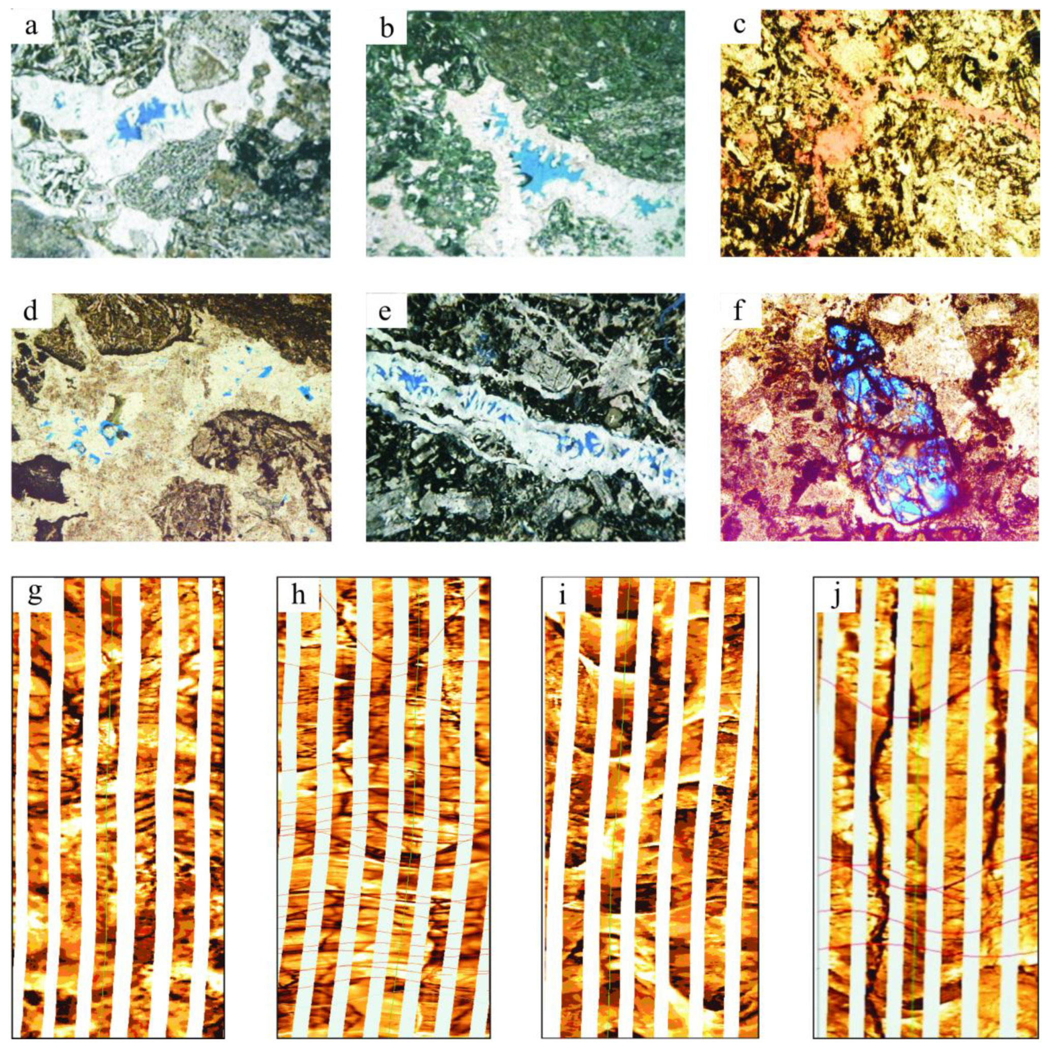
The reservoir space of the Carboniferous volcanic reservoirs in the Chepaizi Uplift is predominantly composed of primary pores, dissolution pores, and fractures. A few primary pores, such as intra-granular dissolved pores and inter-granular pores, are seen in volcanic reservoirs (Figure 2a,b). The casting thin sections show that the vesicles are different in shape and size and have uneven distributions; they are mostly filled with calcite and chlorite and present themselves as semi-filling or amygdales, with inferior storage capacity. Volcanic rocks formed by the volcanic central eruption are mostly isolated, with poor connectivity between rock bodies and vesicles in reservoirs, and isolated primary pores have limited storage capacity. During the diagenesis of volcanic rocks, due to changes in temperature, pressure, and formation fluids, multiple mineral components in the rock body are dissolved and various secondary pores are formed [12]. Secondary pores, such as matrix-dissolved pores and intra-granular dissolved pores, are widely developed in volcanic reservoirs in the study area. Matrix-dissolved pores are secondary pores formed by fluid dissolution of the lava matrix part or soluble components of pyroclastics, which is common in andesite, basalt, and volcanic breccia and generates pores with irregular shapes and relatively small sizes (Figure 2c,d). The dissolved pores are intra-granular dissolved pores and phenocryst-dissolved pores formed via the dissolution of pyroclastics and lava phenocrysts (Figure 2e,f). The imaging logging interpretation shows that the fractures of the Carboniferous reservoir are well developed, but the intensity of fracture development is different in different structural positions and at different well intervals. In other words, the heterogeneity of fractures is high. All fractures are secondary fractures and there are no primary laminated or columnar joints. Four types of fractures are identified, namely, oblique fractures, network fractures, high-angle fractures, and filled fractures, among which the effective fractures are predominantly oblique fractures, followed by network fractures (Figure 2g–j).

4.4. Fine Depiction of Volcanic Rocks

Volcanic activities in the southern part of the Chepaizi Uplift are controlled by the Hongche fault and the volcanic rocks feature multi-cycles of multi-stage eruption and are mainly distributed in the upper plate of the Hongche fault. Volcanic eruption in the study area is mainly characterized by the complete development of the explosive facies and overflow facies. Large breccia bodies are developed in the explosive facies, while thick andesite bodies and basaltic andesite bodies are mainly developed in the overflow facies. Furthermore, thin mudstone layers are deposited during the intermission of the volcanic eruption. From the Well C47 district to the Well CF6 district, the multi-stage volcanic eruption characteristic is observed with the clear lithologic and lithofacies interfaces identifiable on seismic profiles. Different volcanic lithologic associations have different seismic reflection characteristics on seismic profiles [13]. Due to the differences in stages and scales of volcanic eruptions that inevitably result in lithologic diversity and complex variability of accumulation structures, the physical properties of volcanic rocks are inevitably highly differentiated and lead to strong reflection amplitudes. Because volcanic lava generally flows from high to low, multi-stage lava stacks over itself, which leads to the oblique and progradation structures, or the wavy structure caused by flow undulation. Furthermore, the flow on the flat terrain forms the parallel laminated structure. Rapid accumulation of clastic rocks from volcanic eruption also leads to disordered accumulation structures or a blank reflection. To sum up, the seismic reflection structure of volcanic rocks is highly diverse.
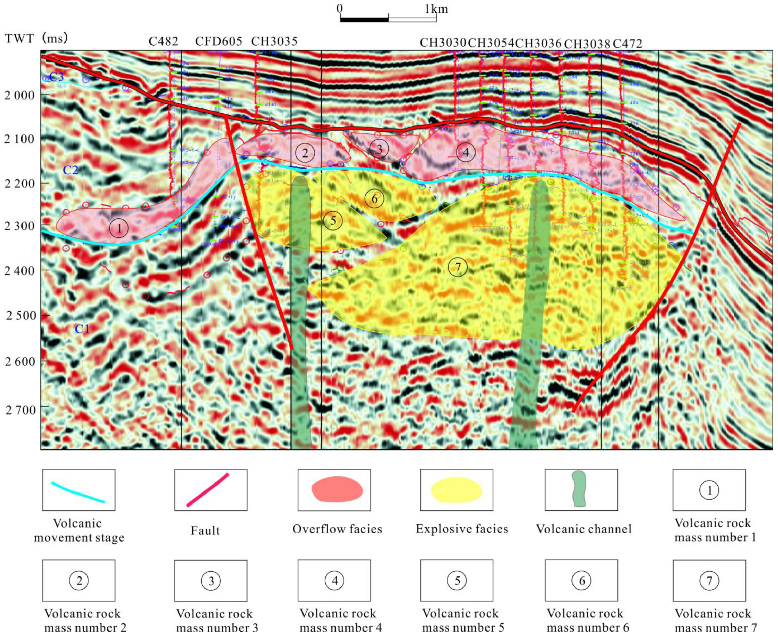
According to the geological and seismic response characteristics of volcanic rocks in the Chepaizi area and the lithologic distribution pattern, the volcanic eruption mode in this area presents a prominent characteristic of central eruption [14]. During the Late Carboniferous, affected by the Late Hercynian movement, the Junggar Basin was initially formed as a closed inland basin. Under the intensive land–land collision around the basin, large-scale volcanic activities occurred in the Junggar Basin. The resultant volcanic rocks have a certain scale and are manifested as interbedding of volcanic rocks and continental clastic rocks, forming a good reservoir-cap rock assemblage in the Carboniferous of the northwest margin of the Junggar Basin [15]. The Carboniferous of the Chepaizi Uplift was formed by the thrust from west to east at the end of the Hercynian movement, before deposition of the Jurassic–Triassic, and its structural pattern was low in the west and high in the east—the uplifted southern part was seriously denuded. Specifically, most of the C3 volcanic rocks were denuded and the C2 and C1 volcanic rocks were relatively intact. The Carboniferous volcanic rocks and overlying surrounding rocks in the study area present highly differentiated seismic reflections. Four overflow volcanic rock bodies can be identified in the C2 stage on the profile, with small mound external shapes and the internal characteristic of low frequency, high-amplitude, and relative continuity, and three explosive volcanic rock bodies are identified in the C1 stage and mostly displayed as the medium-low frequency chaotic reflection on the profile, and low-angle oblique intersected, parallel, and blank chaotic events, with clear impedance interfaces against surrounding rocks. Two volcanic channels can be identified in the C1 stage, with chimney-shaped external shapes, chaotic weak reflection characteristics of internal events, and high-angle unconformity against surrounding rocks (Figure 3). According to the reflection characteristics of seismic events, combined with the lithofacies and lithologic characteristics of wells, seven volcanic rock bodies were identified in the Carboniferous volcanic rocks in the study area. The burial depth of the Carboniferous volcanic edifice is 2400–3000 m (predominantly about 2500 m). Volcanic rocks vertically stack over each other, with different stages, different lithologies, and different lithofacies as interfaces. In a plane view, along the Hongcheguai fault, volcanic rock bodies are distributed in the bead-string form, stacking over each other to generate a continuous distribution with an area of 1.5–13.6 km2 and a volcanic rock distribution area of nearly 50 km2, which is main accumulation area of Carboniferous volcanic reservoirs in the study are.

4.5. Oil–Water Distribution Characteristics

When hydrocarbons enter the reservoir rock from the source rock, they migrate in the direction with minimum resistance, under the joint effects of buoyancy, hydrodynamic force, and capillary force. Moreover, due to gravity differentiation, hydrocarbons accumulate along the upward dip direction of the geological structure to form oil reservoirs, and formation water seepages downward and accumulates in the low part of the structure to form the oil–water contact interface that changes with the structural shape. In one trap there often exists a unified oil–water interface [16]. In the Carboniferous volcanic reservoir of the study area, the oil–water distribution is usually based on volcanic rock bodies. The oil–water distributions for adjacent volcanic rock bodies are independent of each other and there may also be multiple oil–water interfaces in one volcanic rock body.
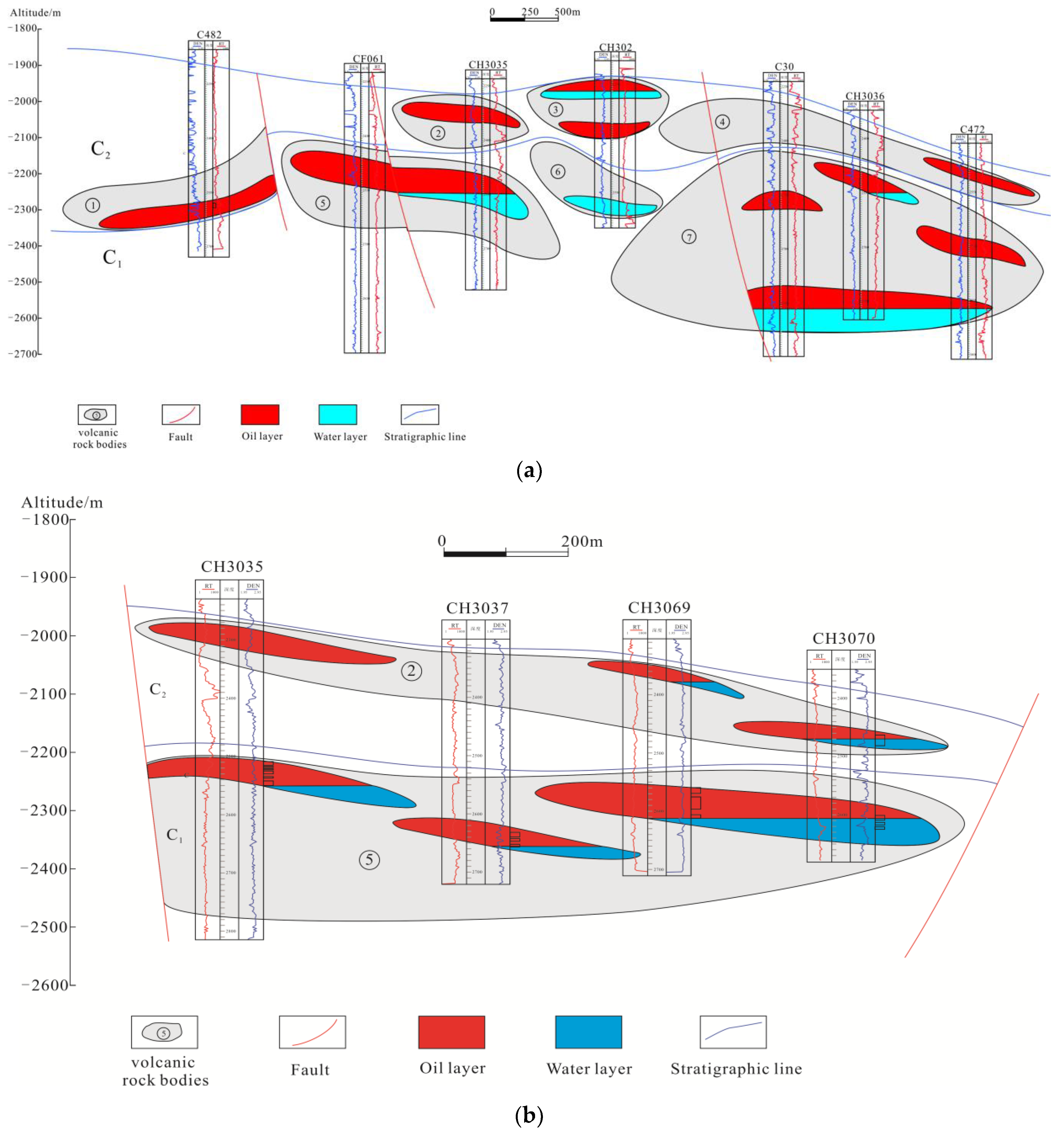
The oil–water distribution of volcanic reservoirs in the study area is uneven. Vertically, the oil layers are mostly distributed in the C2 stage, while the oil–water and water layers are concentrated in the C1 stage of the Carboniferous. The overall distribution follows the law of upper oil and lower water. The distribution of volcanic rock reservoirs is constrained by volcanic rock bodies, and there are considerable differences in oil–water distribution among different volcanic rock bodies—they have different oil–water interfaces. Four overflow-facies volcanic rock bodies were developed in the C2 stage. Drilling confirmed that the oil–water interfaces of the No. 1–3 volcanic rock bodies are at altitudes of 2275–2612 m with an altitude span of 237 m, and different fault blocks of the same volcanic stage develop different oil–water interfaces. Furthermore, drilling confirmed that the oil–water interfaces of the No. 2–3 volcanic rock bodies are at altitudes of 2250–2350 m, which indicates that different volcanic rock bodies in the same fault block of the same volcanic stage are associated with different oil–water interfaces (Figure 4a). In addition, one volcanic rock body may have multiple different oil–water systems. The altitudes of the oil–water interfaces of the No. 5 volcanic rock body, developed in the C1 stage of the fault block of Well CH3069, range from 2257.1 m to 2313.2 m, with a span of 56 m, as is made evident by drilling (Figure 4b). For Carboniferous volcanic reservoirs, hydrocarbon emplacement is based on the units of volcanic rock bodies, which are separated by barriers of lithology and physical properties and develop independent oil–water systems—adjacent volcanic rock bodies in the same fault block have different oil–water interfaces. Additionally, within one volcanic rock body, there are still multiple oil–water interfaces, due to the internal heterogeneity of reservoir physical properties.

5. Discussion

5.1. Matching between Faults and Source Rocks Controls the Macro-Scale Distribution of Oil Reservoirs

The Carboniferous source rocks are revealed by both the surface outcrops and drilled wells in the Chepaizi area. Most Carboniferous source rocks have low abundance and inferior types of residual organic matter, yet with high maturity [17]. The vitrinite reflectance of the drilled Carboniferous source rocks is more than 2%, representing the over-mature stage. The Carboniferous source rocks in this area have few contributions to hydrocarbon accumulation [18]. The Chepaizi area is close to the hydrocarbon-generating Shawan Sag, which has many sets of source rocks in the mature-highly-mature stage. Specifically, the source rocks of the Permian Fengcheng Formation and Wuerhe Formation generate both oil and gas, with a dark mudstone thickness of 100–250 m, which provides a solid material basis for multilayer hydrocarbon accumulation in the Chepaizi area [19,20]. The Chepaizi Uplift itself has no hydrocarbon generation and the crude oil in its Carboniferous mainly comes from the Permian Fengcheng Formation and Wuerhe Formation source rocks [21]—the Carboniferous oil reservoirs feature two stages of hydrocarbon accumulation from different sources.
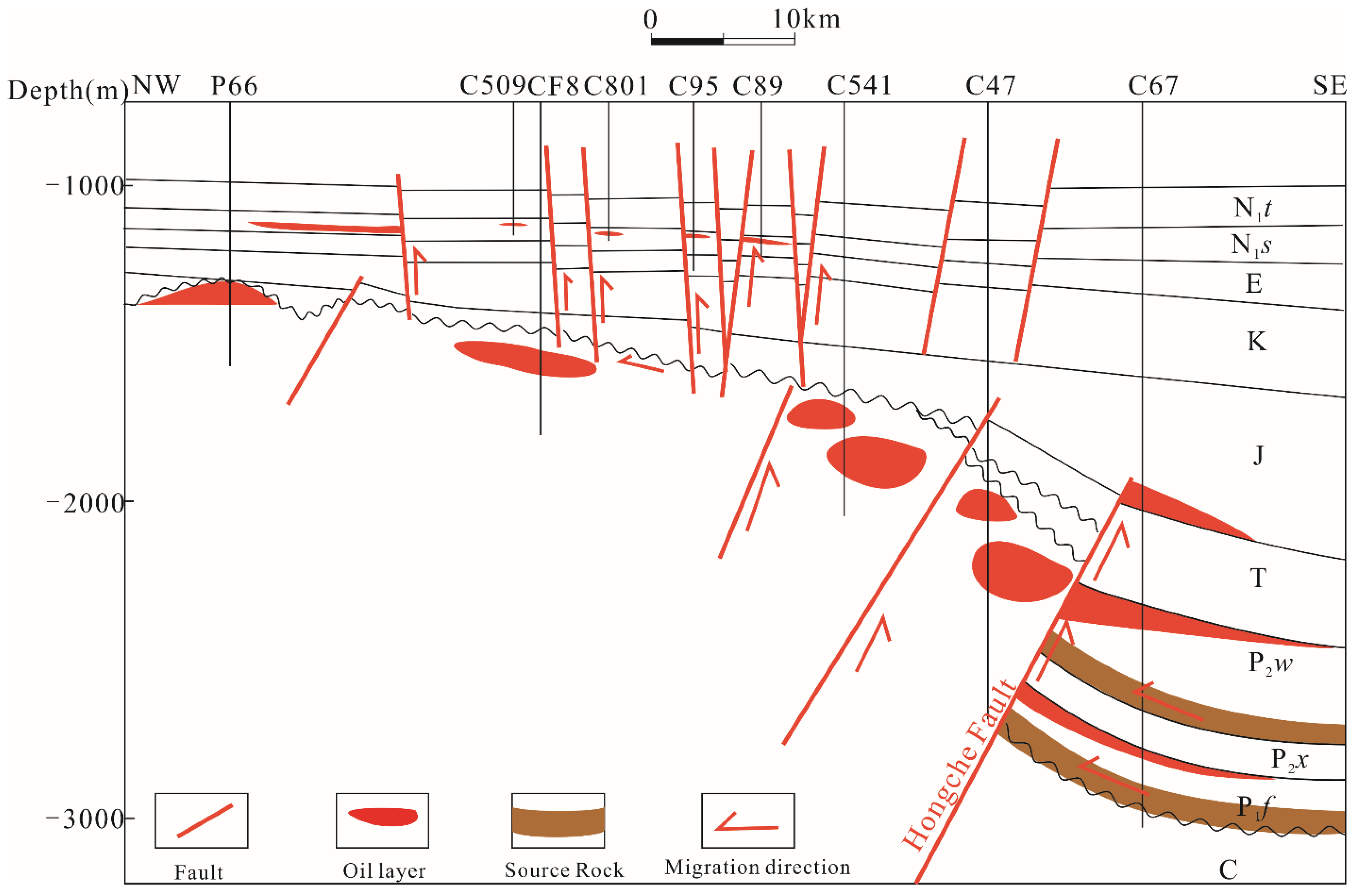
Hydrocarbons generated by adjacent hydrocarbon-generating sags need faults through the hydrocarbon kitchen for subsequent migration, accumulation, and reservoir formation. A group of nearly NS reverse faults was developed in the Carboniferous of the Chepaizi area, namely the Hongche fault. It was formed during the Late Hercynian movement, and the faulting was intensive from the beginning and calmed down by the deposition of the Jurassic. For the upper plate of the Hongche fault, the overlying Permian and Triassic suffered severe denudation—the Triassic was entirely missing while some of the Permian was preserved. Therefore, the Jurassic was deposited over the Carboniferous and Permian. The fault experienced tectonic activities of multiple stages, which remained active until the Mid-Late Jurassic. It served as an important channel for hydrocarbon migration and controlled the stratigraphic distribution of the Chepaizi Uplift, which was gradually raised from east to west, accompanied by promoted denudation. This group of reverse faults, caused by the uplift compression stress, is the main fault communicating the deep source rocks. It extends more than 20 km horizontally and presents the NW–dipping and NW–NE strike. The fault scale is large. The faults extend toward the deep Carboniferous at a high angle on the profile and vertically upward cut the overlying younger strata. The regional deep large fault plays an important role in cutting the Permian source rocks and enabling vertical hydrocarbon migration. The NE-trending secondary faults later occurred along the main faults, divided the Carboniferous into several small fault blocks, and connected the Carboniferous reservoir space [22]. Vertically upward, the faults cut multiple sets of strata, and additionally present extended lateral reach and connect the Permian source rocks in the Shawan Sag in the east with the weathering crust reservoirs in the upper part of the Carboniferous, which ultimately forms the banded distribution pattern of Carboniferous volcanic reservoirs along the Hongche fault (Figure 5).

5.2. Volcanic Rock Bodies Constrain Reservoir Distribution

The Chepaizi area experienced multiple stages of volcanic activity, with different stages of lithology, and lithofacies serving as stratigraphic interfaces. The resultant volcanic rock bodies vertically stack over each other and present the bead-string planar distribution along faults. Different volcanic rock bodies are separated from each other by barriers of lithology and physical properties. Volcanic activities in the study area are characterized by the central eruption. As the energy of the volcanic eruption declines, volcanic rocks gradually transition from basic to neutral. The volcanic rock lithofacies sequence is composed of all or some of the volcanic channel facies, eruption facies, overflow facies, and volcanic sedimentary facies. The top of the Carboniferous is predominated by the overflow facies volcanic rock body mostly of andesite basalt, and the deep is seen with the eruption facies volcanic rock body mainly of volcanic breccia. During the intermission in the volcanic eruption, deposition occurs, which results in the vertical interbedding of volcanic rocks and continental clastic rocks and the reservoir-cap-rock assemblage contained within the volcanic rock body [23,24]. The predominant development of volcanic rocks is the main characteristic of the Carboniferous in Chepaizi. Multi-stage volcanic activities lead to diverse lithology, different shapes, and complex structures. The temporal and spatial distribution and configuration of lithology and lithofacies control the development and distribution of volcanic lithologic traps [25,26].
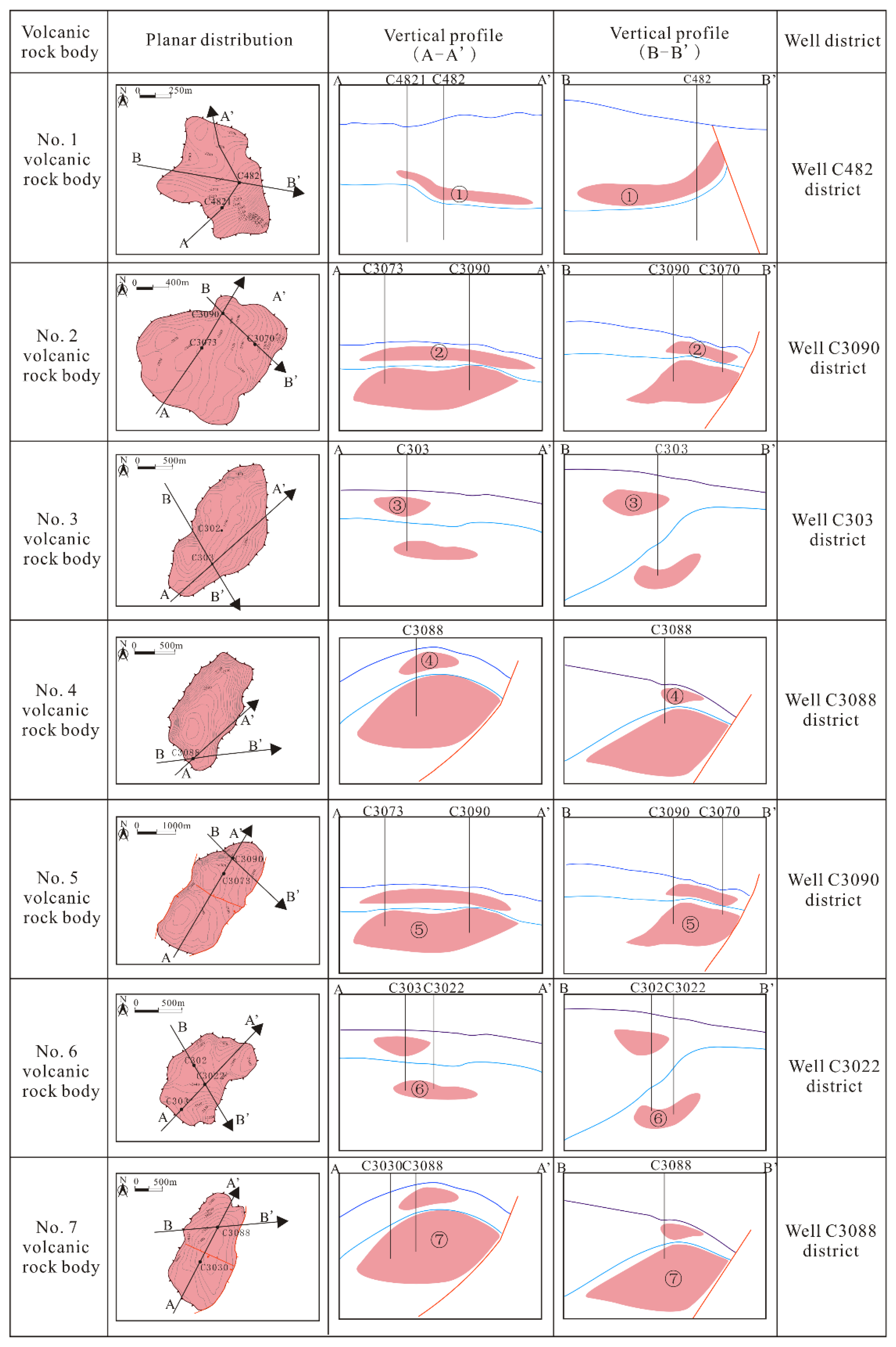
Comprehensive analysis of the lithofacies, well-logging facies, and seismic facies demonstrates the development of two volcanic channels in the study area. According to the volcanic eruption sequence, three explosive volcanic rock bodies are developed in the C1 stage and four overflow volcanic rock bodies are developed in the C2 stage (Figure 6). The main lithology of volcanic rock reservoirs in the study area is andesite, basalt, and volcanic breccia. The explosive-facies volcanic breccia presents the best performance in formation testing and production testing, mainly because different volcanic rock lithofacies have different internal structural characteristics and rock mineral composition, which lead to various reservoir space associations with different properties and scales, formed during tectonic movement and weathering [27]. The volcanic breccia of the explosive facies in the study area is mainly distributed in the Wells C3022, C3090, and C3088 districts, with the bead-string distribution along the Hongche fault. Moreover, the overflow facies are located in the C2 stage and present partial stacking with the explosive facies of the C1 stage. According to the production testing of drilling exploration and development wells, most wells of explosive volcanic breccia in the study area are found with industrial oil streams and drilled basalt of overflow facies presents good hydrocarbon shows. Drilling proves that the explosive volcanic breccia and overflow basalt in the Chepaizi area are favorable lithology and lithofacies for hydrocarbon accumulation in this area. Due to the differences in lithology and physical properties among volcanic rocks, hydrocarbons accumulate and form reservoirs in various volcanic rock bodies, which results in lithologic reservoirs under the fault block setting. The multi-stage volcanic eruption leads to the vertical stacking of volcanic rock bodies and the development form of volcanic rock bodies constrains the distribution range of reservoirs, which is manifested as the characteristic of “one body for one reservoir” under the structural setting—each volcanic rock body can serve as an independent unit for hydrocarbon accumulation [28].

5.3. Structural Evolution Adjusts the Reservoir Distribution Pattern

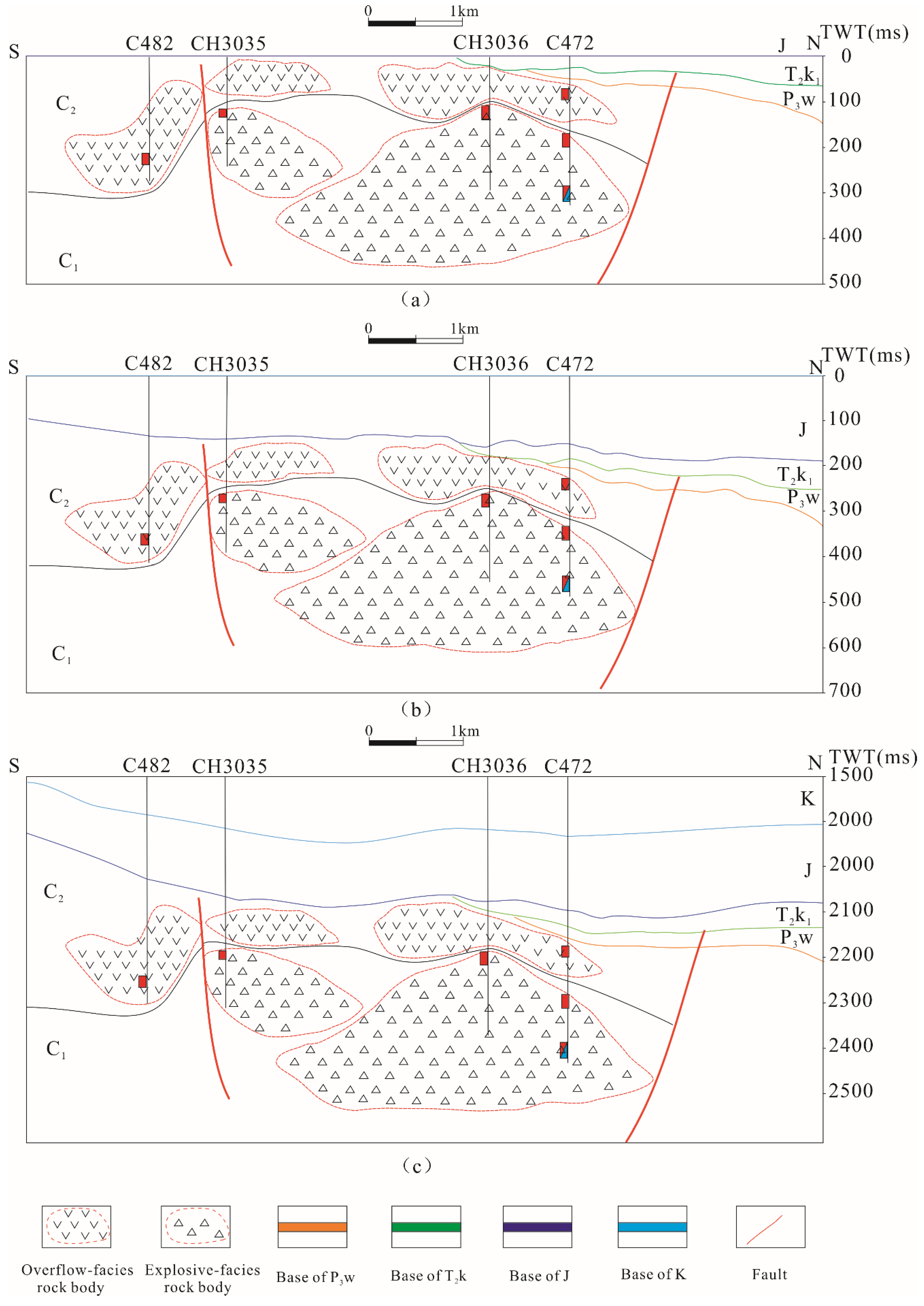
Tectonism is an important factor affecting the distribution of volcanic reservoirs. The Chepaizi Uplift is an inherited paleo-uplift formed on the Carboniferous volcanic basement. Carboniferous volcanic rocks have experienced intensive uplift and slow subsidence after their formation, which is critical for the formation and modification of volcanic reservoirs. At the end of the Triassic, the overflow volcanic rock body of the shallower Carboniferous C2 stage in the Chepaizi Uplift was high in the south and low in the north, while the explosive breccia rock body of the deeper Carboniferous C1 stage shows an opposite trend—high in the north and low in the south (Figure 7a). Meanwhile, the source rocks of the Permian Fengcheng Formation in the Shawan Sag reached their peak in oil generation, and the first emplacement of generated hydrocarbons was completed from the Late Triassic to the Jurassic [29]. According to the theory of differentiated hydrocarbon accumulation, the southern part of the shallower C2 stage is closer to the crater and has better physical properties, and consequently, the hydrocarbon emplacement in the southern overflow volcanic rock body is higher than that in the north—in a plane view, the southern wells are found to have high production, while the northern wells are dry. The deeper C1 stage shows a structural pattern high in the north and low in the south, and the hydrocarbon emplacement of explosive facies rock bodies in the north is higher than that in the south, which is manifested as the planar transition from pure oil to oil–water co-existence from north to south. The end of the Jurassic is associated with the second hydrocarbon accumulation, during which the overall structure of the Carboniferous in the Chepaizi Uplift is an inherited uplift—the shallower C2 stage is still high in the south and low in the north, while the deeper C1 stage is high in the north and low in the south (Figure 7b). The shallower overflow facies underwent a secondary hydrocarbon emplacement and the fullness of hydrocarbons of the overflow facies in the south is higher than that of the north. The Himalayan movement is a period of hydrocarbon accumulation adjustment, during which the shallower overflow facies rock body is high in the north and low in the south, and the deeper explosive facies rock body is high in the south and low in the north. However, due to the high heterogeneity of volcanic rocks, the adjustment is suppressed, and the hydrocarbon distribution pattern of these volcanic rock bodies is essentially unchanged (Figure 7c).
The physical property differentiation of the different volcanic rock bodies and the paleo-structure jointly determine the level of hydrocarbon emplacement of volcanic rock bodies. Better physical properties and higher structural positions of volcanic rock bodies are subjected to more sufficient water displacement by oil and thus higher oil content. The physical properties of the explosive facies volcanic rock body near the crater are better than those of the overflow facies. In the deeper C1 stage, the hydrocarbon emplacement in the higher northern part of the structure is more intensive than that in the lower southern part of the structure. As for the shallower C2 stage, affected by the paleo-structure, it shows a trend of being high in the south and low in the north. The volcanic rock bodies in the southern part are closer to the crater and have better physical properties, compared with those in the north. The above-mentioned leads to the differentiated distribution of oil, gas, and water of the carboniferous oil reservoirs—different at different depths and different in different positions along the north–south direction.

5.4. Reservoir Physical Properties Control the Differentiation of Oil, Gas, and Water

Micro-scale pores of reservoirs are both the reservoir space of crude oil and the main micro-scale pathways for hydrocarbon emplacement. The quality of the pore structure directly determines the differentiation of oil and water in volcanic reservoirs [30]. The reservoir with good physical properties has small capillary pressure and small resistance to hydrocarbon emplacement, while the reservoir with poor physical properties has relatively larger resistance to hydrocarbon emplacement and needs higher initial displacement pressure, which means greater difficulties for oil and gas in entering such reservoirs and displacing formation water. Therefore, hydrocarbons preferentially accumulate in reservoir rocks with good physical properties. The analysis of 32 samples of the Chepaizi Uplift shows that the porosity of the water layer and oil-bearing layer is mainly distributed in 4.0%–12.8%, and the permeability is (0.063–0.314) × 10−3 μm2, while the porosity of the oil–water layer and oil layer is 6.3%–18.6% and the permeability is (0.23–4.83) × 10−3 μm2, respectively. Clearly, the latter two layers present physical properties better than those of the former two layers (Figure 8). The throat radius of the oil layer and oil–water layer samples is relatively larger, associated with the smaller capillary pressure and lower resistance to hydrocarbon migration under the same conditions. The complex lithology and physical properties of volcanic rock bodies form a complex micro-pore structure, which makes it difficult for the formation water to be fully displaced during hydrocarbon accumulation. Therefore, high-formation water saturations are present in reservoirs with poor physical properties, which hinder hydrocarbon migration along the upward dip direction. Because of reservoir heterogeneity, volcanic rock bodies are subjected to differentiated hydrocarbon emplacement—crude oil is enriched in the reservoir rocks with good physical properties, while the reservoir rocks with inferior physical properties are mostly water layers and oil-bearing layers.
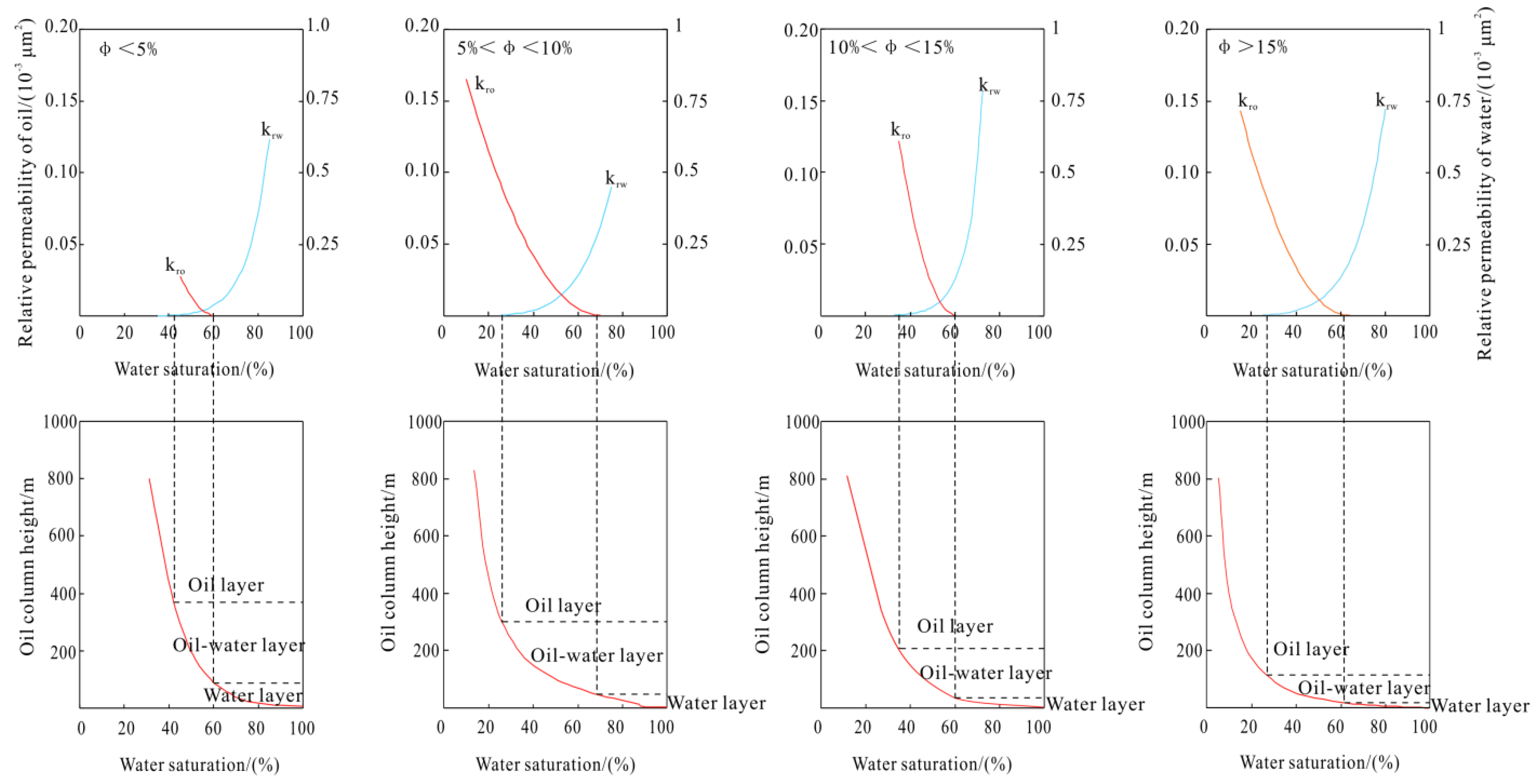
Under reservoir conditions with similar dip angles and crude oil density, the magnitude of net buoyancy is closely related to the height of the pure oil column. In reservoirs with relatively good physical properties, the oil column height required for internal oil–water differentiation is small. Yet, under the same structural conditions, reservoirs with poor physical properties need a higher closure height for oil–water differentiation and tend to form a wider oil–water transition zone [31]. By overlapping the capillary pressure and relative permeability curves, the lowest closure height of the actual reservoir and the position and thickness of the oil–water transition zone can be determined [32,33,34,35,36,37]. According to the high-pressure mercury injection data and relative permeability curves of the reservoirs in the study area, the oil column height for the oil–water differentiation of the Carboniferous volcanic rocks was calculated. The results show that with the increasing reservoir porosity, the oil column height required for complete oil–water differentiation gradually decreases; the oil column height required for oil–water differentiation in the reservoirs of the study area is 125–382 m (Figure 9). The structural amplitude of volcanic lithologic traps in the study area is 70–350 m, and complete oil–water differentiation can be realized only in the traps in higher structural positions and with relatively good physical properties in volcanic rock bodies, while those with low closure height and poor physical properties at the edges of volcanic rock bodies are mostly characterized by wide and gentle oil–water transition zones. Defining the distribution range of the oil–water transition zone in the volcanic rock body is of great significance for determining the water-avoiding height of development wells during the development deployment.
The Carboniferous volcanic reservoir in the Chepaizi Uplift is not a fault block reservoir but a lithologic reservoir. The complex oil–water relationship inside the reservoir is not controlled by the fault block, but is mainly controlled by the physical properties of the reservoir inside the rock mass that leads to each rock mass having a relatively independent oil–water relationship. The difference in the physical properties within the same rock mass leads to incomplete oil and gas filling, which is manifested as sufficient oil and gas displacement in reservoirs with good physical properties located in the high parts, and insufficient oil and water displacement in reservoirs with poor physical properties located in the low parts. Well CH3035, which perforated the high part of No.2 overflow facies rock mass, has relatively good reservoir physical properties, and the interpreted porosity can reach 12%, which is filled with pure oil. However, well CH3070 in the lower part has relatively poor physical properties with an interpreted porosity of 4.5% which is confirmed as an oil–water layer. In No. 7 burst facies rock mass, the upper part of well C30 has relatively good physical properties, with a porosity of 13.8% and horizontal permeability of 1.62 mD, which is proved to be a pure oil layer by an oil test, while the lower part of well C30 has poor physical properties, with a porosity of 6.7% and horizontal permeability of less than 0.01 mD, which is proved to be an oil–water layer by an oil test. As the microscopic transport system in the process of oil and gas filling, the microscopic pore of the reservoir determines the oil and water differentiation state in the volcanic rock mass. The oil and gas displacement of the reservoir with good physical properties is fully manifested as a pure oil reservoir. As the physical properties of the reservoir become worse, the interior of the reservoir shows a wide and slow oil–water transition zone, and the oil-bearing capability gradually becomes worse. The physical properties of the volcanic rock mass are different due to the different lithology, which determines the difference of oil and water in the reservoir.

5.5. Hydrocarbon Accumulation Model

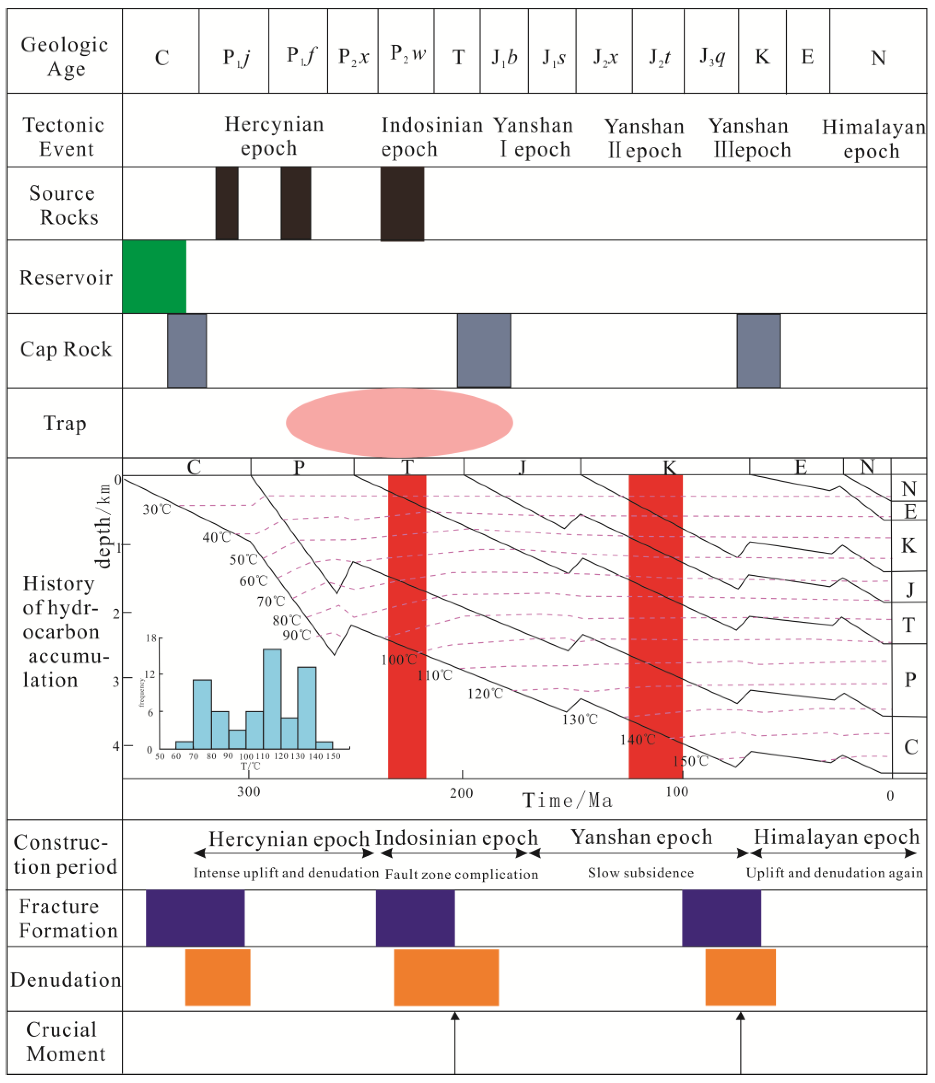
Multi-stage tectonic movements have created a complex structural framework of the Chepaizi Uplift. The strata of the Chepaizi Uplift feature the EW banded distribution and the geological structure is characterized by being high in the west and low in the east. The Chepaizi Uplift was finalized during the Hercynian movement. The Hongche fault system was formed during the Indosinian tectonic movement, and moreover, the Carboniferous suffered from long-term uplift and weathering to form unconformity. The complex pathway system, composed of faults penetrating oil sources and the unconformity interface, provides good migration channels for hydrocarbons generated by the source rocks in the Shawan Sag, which contributes to the final formation of lithologic oil and gas plays controlled by faults. The Chepaizi Uplift experienced two stages of hydrocarbon accumulation during the Late Triassic and Late Jurassic, respectively. The source rocks of the Permian Fengcheng Formation in the Shawan Sag reached a peak of hydrocarbon expulsion during the Late Triassic and the hydrocarbons generated by the Fengcheng Formation accumulated in the volcanic lithologic traps in the higher position of the southern part of the uplift along the migration channel of the Hongche fault zone and the unconformity at the top of the Carboniferous. During the Late Jurassic, the second stage of hydrocarbon accumulation arrived (Figure 10). The source rocks of the Permian Wuerhe Formation in the Shawan Sag reached a peak of hydrocarbon expulsion and hydrocarbon accumulation and emplacement occurred in the volcanic lithologic traps in the higher positions of the subordinate structure along the main pathway system to form oil and gas plays. The Late Cretaceous was associated with the hydrocarbon distribution adjustment and the geological structure was reformed by the Yanshanian tilting movement. The northern part of the Chepaizi area was gradually uplifted to form a structural pattern of being high in the north and low in the south, and in the traps in the higher northern part of the structure, hydrocarbon accumulation and emplacement occurred to form oil and gas plays, which finalized the north–south distribution pattern of the Carboniferous reservoirs across the Chepaizi Uplift (Figure 11).

6. Conclusions

(1)
The Carboniferous volcanic rock reservoir in the Chepaizi Uplift is composed of seven volcanic rock bodies developed under the fault block setting. The volcanic rock bodies vertically stack over each other and present a bead-string connected planar distribution along the Hongcheguai fault, with a volcanic rock distribution area of nearly 50 km2, which features the concentration of Carboniferous volcanic rock reservoirs in the study area.
(2)
The oil–water relationship of the Carboniferous volcanic rocks is complex. The oil–water distribution is usually based on units of volcanic rocks. The oil–water distributions in adjacent volcanic rock bodies are independent of each other and there may be multiple oil–water interfaces within one volcanic rock body.
(3)
The Carboniferous volcanic reservoir experienced two stages of hydrocarbon accumulation from different source rocks. The distributions of faults penetrating hydrocarbon kitchens and source rocks control the macro-scale distribution of reservoirs, while the physical properties of reservoirs determine the oil–water differentiation in volcanic rock bodies. The lithofacies-controlled model highlighting “one rock body for one reservoir” decides the distribution of reservoirs and the matching between the paleo-structure and hydrocarbon accumulation stages controls the accumulation and adjustment of hydrocarbons. The hydrocarbon accumulation model of the Carboniferous volcanic reservoirs in the Chepaizi Uplift is summarized as two stages of hydrocarbon accumulation of newly generated oil and gas into older reservoir rocks with different source rocks. Specifically, the Permian source rocks in the Shawan Sag offer lateral hydrocarbon supply and hydrocarbons accumulate in the Carboniferous structural-lithologic traps. The findings of this research provide guidance on the efficient development of the volcanic reservoirs with complex oil–water relationships in the study area.

Author Contributions

Conceptualization, X.L. and H.P.; methodology, Y.W.; formal analysis, and G.L.; investigation, J.S. and K.G.; resources P.J., S.W., T.L. and L.Z.; writing original draft preparation, H.P. and S.W.; writing—review and editing, X.L. and L.Y.; visualization, S.W. All authors have read and agreed to the published version of the manuscript.

Funding

This research was funded by PetroChina Major Science and Technology Project which named research and application of key technologies for profitable development of volcanic reservoir. The funding number is 2017E-0405.

Data Availability Statement

Data will be made available upon request.

Acknowledgments

We would like to thank CNPC for permission for the release of this study. We appreciate the valuable comments from the editors and anonymous reviewers.

Conflicts of Interest

The authors declare no conflict of interest.

References

  1. Jin, J.; Wang, J.; Yang, Z.; Liu, J.; Ji, H.C.; Jia, H.B.; Zhang, X.G. Well logging identification of Carboniferous volcanic inner buried-hill reservoirs in Ke-Bai Fault Zone in Junggar Basin. Lithol. Reserv. 2018, 30, 85–92. [Google Scholar]
  2. Wang, L.; Li, J.H.; Shi, Y.M.; Zhang, L.W. The identification and prediction of Carboniferous volcanic rocks in Dixi area, Junggar Basin. Acta Petrol. Sin. 2010, 26, 242–254. [Google Scholar]
  3. Pan, H.; Li, X.; Qian, C.C.; Song, J.Q.; Luo, G.X. Characteristic and accumulation Patterns of Carboniferous Inside-Type volcanic Reservoir in Kebai Fault Zone of Junggar Basin. J. Northeast. Pet. Univ. 2022, 46, 62–75. [Google Scholar]
  4. Huang, Y.; Liang, S.Y.; Yang, D.S.; Ji, D.S.; Fu, X.P. Characteristics and Main Controlling Factors of Primary Rhyolite Volcanic Reservoir. Spec. Oil Gas Reserv. 2021, 28, 54–61. [Google Scholar]
  5. Masab, A. Pore Structures and Reservoir Characteristics of Volcanic Rocks. In The Carboniferous Batamayineishan Formation in Shuangjingzi Area, Eastern Junggar Basin; Jilin University: Jilin, China, 2021; pp. 16–23. [Google Scholar]
  6. Wang, K.; Feng, Z.; Zhang, Y.; Wang, D.K. Identification of the lithology of Carboniferous and its reservoir characteristics in Chepaizi uplift, Junggae basin. J. Southwest Pet. Univ. Sci. Technol. Ed. 2014, 36, 21–28. [Google Scholar]
  7. Cheng, C.L.; Sun, Y.; Zhang, F.; Shang, F.K.; Yuan, L.; Ren, X.C. The control factors and distribution of favorable gneous reservoirs in Chunfeng oilfield. J. Oil Techenol. 2014, 36, 54–59. [Google Scholar]
  8. Liu, H.J. Study on Hydrocarbon Accumulation Law for Volcanic Rockreservoirs in Hongche Fault Belt, Junggar Basin; China University of Petroleum (EastChina): Qingdao, China, 2013; pp. 52–55. [Google Scholar]
  9. Wang, X.J.; Qi, H.Y.; Wu, B.C.; Zhou, L.J. A New Understanding of the Carboniferous Oil Reservoir and Its Rolling Evaluation Practice in the Chepaizi Area; Shanxi Petroleum Society: Xi’an, China, 2018; pp. 1–6. [Google Scholar]
  10. Xing, F.C.; Lu, Y.C.; Liu, C.H.; Xiang, K. Structural-paleogeomorphologic features of Chepaizi area and mechanism of their control on sandbodies. Oil Gas Geol. 2008, 29, 79–83. [Google Scholar]
  11. Shang, F.K.; Chen, L.; Wang, L.; Han, Z.H.; Liu, Z.C. Main controlling factor and hydrocarbon accumulation modes of volcanic rock oil reservoirs in Chepaizi Uplift. J. Northeast. Pet. Univ. 2015, 39, 13–22. [Google Scholar]
  12. Liu, W.F.; Liu, S.L.; Sun, L.X. Type and Characteristics of Permian Andesite Reservoir in Tiaohu Sag, Santanghu Bain. XJPG 2000, 21, 483–486. [Google Scholar]
  13. Yu, B.L.; Liu, X.L.; Fan, S.F.; Liu, H.; Wang, K.M. Seismic Technique and Application of Volcanic Rock Facies. Xinjiang Pet. Geol. 2009, 30, 264–266. [Google Scholar]
  14. Qiu, J.; Zeng, G. Early Paleozoic Marine Volcanic Rocks and Mineralization in Lajishan; China University of Geosciences Press: Wuhan, China, 1997; pp. 54–61. [Google Scholar]
  15. Li, J. The Study on Distribution Characteristies and Controlling Factors of Carboniferous Volcanic Reservoir of the Northwestern Margin, Junggar Basin; China University of Geosciences: Beijing, China, 2008; pp. 55–58. [Google Scholar]
  16. McMasters, G.E. Deep Reservoirs basin gas trap, western Canada. AAPG Bull. 1979, 63, 152–181. [Google Scholar]
  17. Wang, X.L.; Zha, M.; Xia, H.P.; Chen, Z.H.; Kong, Y.H.; Jiang, R.F. Forecast and Assessment of Oil and Gas Resources in Carboniferous, Northern Xinjiang. Adv. Earth Sci. 2012, 27, 80–85. [Google Scholar]
  18. Gao, G.; Wang, X.L.; Liu, G.D.; Zhang, Y.Q.; Huang, Z.L. Analyses of the Genesis and Potential of Natural Gas in Kebai Area of Northwest Margin, Jungar Basin. Geol. J. China Univ. 2012, 18, 307–317. [Google Scholar]
  19. Chen, S.J.; Zeng, J.; Wang, X.L.; Li, Y.J. Geochemical study of oil and gas reservoir formation of Hongche area. J. Southwest Pet. Inst. 2004, 26, 1–4. [Google Scholar]
  20. Wang, Z.Q.; Zheng, Y.; Zhi, D.M.; Dang, Y.F.; Xing, C.Z. Hydrocabon Accumulation Patterns of Carboniferous Formation in Chepaizi Area. J. Oil Techenol. 2010, 32, 21–25. [Google Scholar]
  21. Wang, X.; Kang, S.F. Analysis of crude origin in hinterland and slope of northwestern margin, Junggar Basin. Xinjiang Pet. Geol. 1999, 2, 32–36. [Google Scholar]
  22. Liu, P.F. Hydrocarbon Accumulation Characteristics of Carboniferous Volcanic Rocks of Chepaizi Uplift in Junggar Basin; China University of Petroleum (East China): Dongying, China, 2018; pp. 50–56. [Google Scholar]
  23. Sun, F.J.; Luo, X.; Qi, J.S.; Shao, M.L.; Zeng, F.Y.; Jiang, X.H.; Cui, C.G. Controlling effects of volcanic rocks upon gas pools—Taking two volcanic gas reservoirs in the Songliao Basin as examples. Oil Gas Geol. 2010, 31, 180–186. [Google Scholar]
  24. Chen, J.; Wang, J.; Lei, H.Y.; Ma, C.; Meng, Y.; Qi, J. Characteristics of Igneous Weathering Crust Reservoir and Its Relation With Oil and Gas Productivity: A Case Study of the Carboniferous Hongshanzui Reservoir, Junggar Basin. Geoscience 2022, 36, 1009–1021. [Google Scholar]
  25. Liu, J.Q.; Meng, F.C.; Cui, Y.; Zhang, Y.T. Discussion on the formation mechanism of volcanic oil and gas reservoirs. Acta Petrol. Sin. 2010, 26, 1–13. [Google Scholar]
  26. Yuan, S.W.; Li, X.; Shi, L.; Wang, Y.T.; Peng, L.C. Prediction of the lithology distribution of favorable volcanic reservoirs in the inside Carboniferous system in Block 6, 7 and 9 of Karamay Oilfield. Pet. Geol. Oilfield Dev. Daqing 2019, 38, 40–45. [Google Scholar]
  27. Fan, C.H. The Comprehensive Research on Carboniferous Volcanic Rock Reservoir of Zhongguai uplift in Northwestern Margin of Junggar Basin; Chengdu University of Technology: Chengdu, China, 2015; pp. 137–142. [Google Scholar]
  28. Zhou, X.; Yu, S.Q.; Zhang, D.Z.; Yu, H.S.; Chen, X. Characteristics and major controlling factors of gas-water distribution in tight volcanic gas reservoir in Xushen gas field, Songliao Basin. Oil Gas Geol. 2019, 40, 1038–1047. [Google Scholar]
  29. Xu, Y.D.; Wang, L.; Liu, Z.C.; Shi, L.Y. Characteristics of fluid inclusions and time frame of hydrocarbon accumulation for volcanic reservoirs in Chepaizi Uplift. Fault Block Oil Gas Field 2020, 27, 545–550. [Google Scholar]
  30. Wiersberg, T.; Erzinger, J. Origin and spatial distribution of gas at seismogenic depths of the San Andreas Fault from drill-mud gas analysis. Appl. Geochem. 2008, 23, 1675–1690. [Google Scholar] [CrossRef]
  31. Quan, H.H.; Bie, X.W.; Xie, Y.; Zhang, Z.; Wang, Y. Main cotrolling factors analysis on depth difference of oil-water contact based on oil-water sweepage: A case study of NB35-2 oilfieled, Bohai sea. China Offshore Oil Gas 2017, 29, 79–86. [Google Scholar]
  32. Pu, C.S.; Guo, Y.P.; Xiao, Z.L.; Shi, D.H.; Li, Y.Z.; Chen, S. Application of a new-style acid fluid system with deeply pentrability in extra-low permeability reservoir in Chang8 of Xifeng Oilfield. Pet. Geol. Recovery Effic. 2008, 15, 95–101. [Google Scholar]
  33. Wu, L. Study on Oil-Water Movement and Displacement Law in the Transition Zone of Low-Permeability Oilfield; China University of Petroleum: Beijing, China, 2016; pp. 16–32. [Google Scholar]
  34. Ning, F.X. Main controlling factors and quantitative calculation of oil column height of the stratigrahic hydrocarbon reservoirs in Jiyang Depression. PGRE 2008, 15, 9–11. [Google Scholar]
  35. Cui, Z.H.; Xia, Z.H.; Liu, L.L.; Song, X.Z.; Fan, H.L. Study on production capacity of complex carbonate reservoir by capillary pressure curve and relative permeability curve. Pet. Geol. Recovery Effic. 2011, 18, 89–104. [Google Scholar]
  36. Nilson, R.H. Gas-driven fracture propagation. J. Appl. Mech. 1981, 48, 756–762. [Google Scholar] [CrossRef] [Green Version]
  37. Nilson, R.H.; Proffer, W.J.; Duff, R.E. Modeling of gas-driven fractures induced by propellant combustion within a borehole. Int. J. Rock Mech. Mine Sci. Geomech. 1985, 22, 3–19. [Google Scholar] [CrossRef]
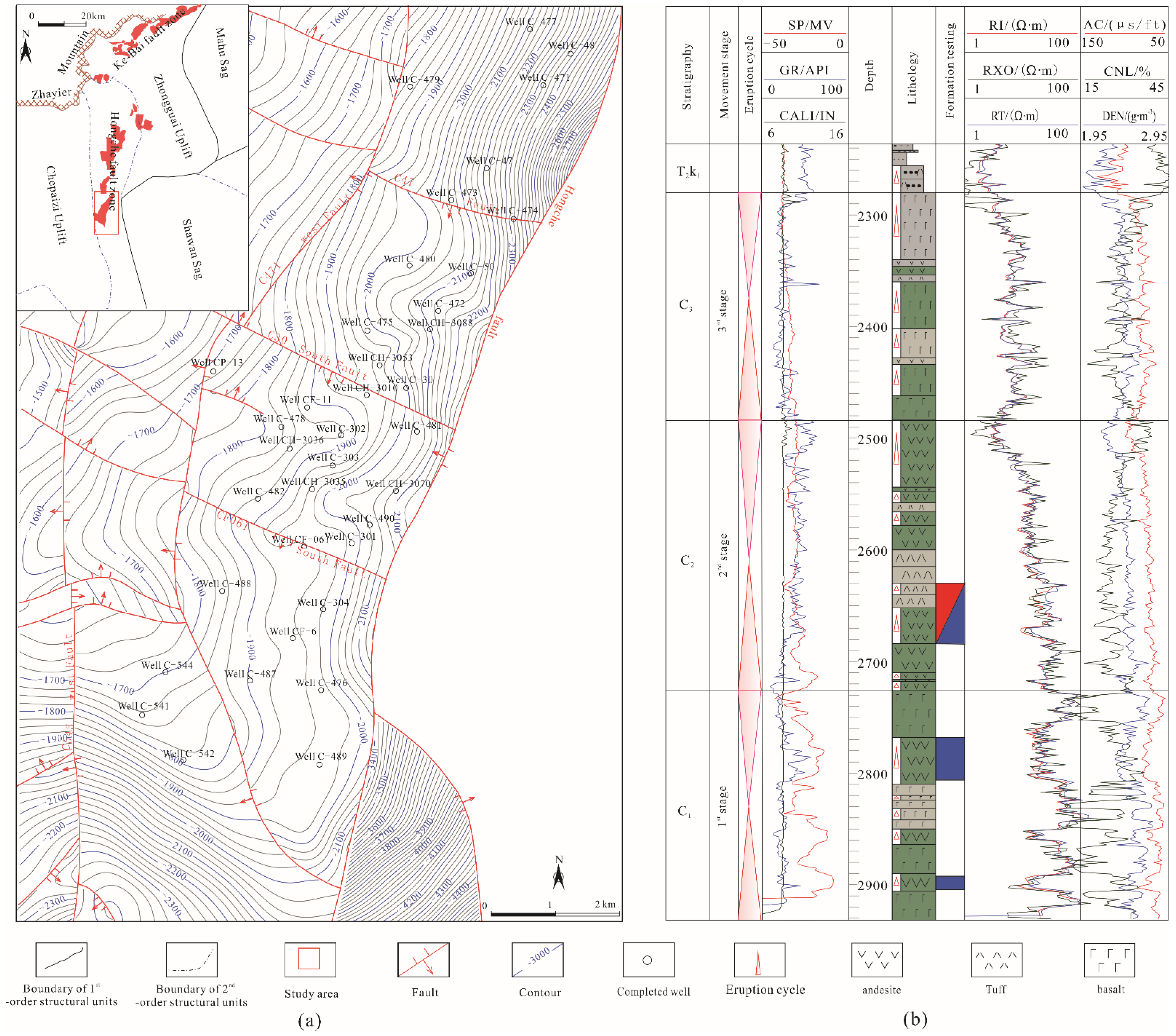
Figure 1. Structural position of the study area (a) and the stratigraphic column of the Carboniferous (b).
Minerals 12 01357 g001
Figure 2. Reservoir space types of the Carboniferous volcanic rock reservoirs in the Chepaizi Uplift. (a) Well C031, 1764.0 m, 100×, andesite, intra-granular dissolved pores; (b) Well CF3, 1755.7 m, 80×, basalt, inter-crystalline pores; (c) Well C47, 2770.9 m, 80×, andesite, 15% matrix dissolved pores, 85% micro fractures; (d) Well C542, 2267.6 m, 50×, basalt, 100% matrix dissolved pores; (e) Well CF6, 2506 m, 25×, volcanic breccia, 5% intra-granular pores, 95% semi-filled fractures; (f) Well C541, 2055.89m,100×, andesite, 80% phenocryst dissolved pores, 20% semi-filled vesicles; (g) Well C471, 2625.1–2628.3 m, network fractures; (h) Well C472, 2491.6–2491.5 m, oblique fractures; (i) Well C492, 2029.1–2033.5 m, filled fractures; (j) Well C482, 2492.1–2494.3 m, high-angle fractures.
Minerals 12 01357 g002
Figure 3. Distribution characteristics of volcanic rock bodies of the Carboniferous volcanic reservoirs in the Chepaizi Uplift.
Minerals 12 01357 g003
Figure 4. Profiles of the Carboniferous volcanic reservoir in the Chepaizi Uplift. (a) Reservoir profile cross Wells C482-CF061-CH3050-C472; (b) Reservoir profile cross Wells CH3035-CH3037-CH3069-CH3070.
Minerals 12 01357 g004
Figure 5. Distributions of the Permian Fengcheng Formation source rocks and faults in and around the Chepaizi Uplift.
Minerals 12 01357 g005
Figure 6. Planar distributions and vertical profile of Carboniferous volcanic rock bodies in the Chepaizi Uplift. ① The number one of the overflow facies volcanic rock body, the trap area is 0.62 km2; ② The number two of the overflow facies volcanic rock body, the trap area is 2.08 km2; ③ The number three of the overflow facies volcanic rock body, the trap area is 3.5 km2; ④ The number four of the overflow facies volcanic rock body, the trap area is 1.3 km2; ⑤ The number five of the explosive facies volcanic rock body, the trap area is 4.6 km2; ⑥ The number six of the explosive facies volcanic rock body, the trap area is 0.62 km2; ⑦ The number seven of the explosive facies volcanic rock body, the trap area is 7.2 km2.
Minerals 12 01357 g006
Figure 7. S-N profiles cross Wells C482-C472 in the Chepaizi Uplift, showing structural evolution. (a) The structural section of the flattening the Jurassic formation; (b) The structural section of the flattening the Cretaceous formation; (c) The present structural section.
Minerals 12 01357 g007
Figure 8. Displacement pressure vs. porosity and permeability for the volcanic reservoir in the Chepaizi Uplift.
Minerals 12 01357 g008
Figure 9. Correlation between reservoir physical properties and oil column heights of the Carboniferous reservoir in the Chepaizi Uplift.
Minerals 12 01357 g009
Figure 10. Hydrocarbon accumulation and evolution history of Carboniferous reservoirs in Chepaizi area.
Minerals 12 01357 g010
Figure 11. Hydrocarbon accumulation model of the Carboniferous volcanic rock reservoir in the Chepaizi Uplift.
Minerals 12 01357 g011
Table 1. Evaluation parameters of main source rocks of Permian in Shawan Sag.
FormationTOC
/wt%
S1 + S2
/mg·g−1
Chloroform
Bitumen A
/%
Carbon Isotope
δ13C
/‰
%Ro,ran
/%
Kerogen
Type
P1f1.260.730.15−28.7~−31.90.85~1.16I–II
P2w0.7~1.40.570.0088−25.5~−20.20.86II
Table 2. Main fracture elements of Chepaizi Uplift.
Fault NameFault NatureDisconnect the FormationFault Distance
/m
Attitude of FaultExtension Length
/km
AlignmentDirection
Hongche FaultcompressionalJ~C100~2000NWW29.2
C471 West FaultcompressionalJ~C40~300NWW25.1
C545 West FaultcompressionalK~C10~20NWW28.5
C47 FaultcentripetalC10~80EWS14.5
C30 South FaultcentripetalC10~20EWS5.98
CF061 South FaultcentripetalC10~20EWS5.89
Publisher’s Note: MDPI stays neutral with regard to jurisdictional claims in published maps and institutional affiliations.