Abstract
Focusing on the selective extraction of the critical raw materials indium and germanium from real bioleaching solutions, extended studies have been carried out using Europe’s first underground hybrid membrane pilot plant (TRL6). In order to transfer former laboratory experiments to pilot scale, NF99 (Alfa Laval) was used for the evaluation of membrane permeance and ion retention. A performance test of microfiltration (MF) and nanofiltration (NF) showed high permeances with low root-mean-square deviation under feed variation (5.2% for MF, 4.7% for NF). Depending on the feed load, a significant permeance drop of up to 57% for MF (3 bar) and 26% for NF (10 bar, 1.1 m s−1) was observed. The NF retention performance showed that, without regular chemical cleaning, the selectivity between the target elements degraded. By introducing acidic-basic cleaning steps, it was possible to keep the retention behavior at an approximately constant level (In 91.0 ± 1.3%; Ge 18.2 ± 5.5%). In relation to the specified target, the best results could be achieved at low pressure (7.5 bar) and a maximum overflow velocity of 1.1 m s−1, with a retention of 88.4% for indium and 8.8% for germanium. Moreover, the investigations proved the functionality and long-term stability of the underground membrane device.
1. Introduction
The increasing demand for strategic elements requires innovative and environmentally sustainable methods, which are suitable for both the extraction from increasingly poor, complex, and difficult-to-reach raw materials and their downstream processing [1]. Although recycling can make a significant contribution to resource management and responsible use, the global resource demand cannot be fulfilled, even with a 100% recycling rate [2]. Biohydrometallurgy offers a promising approach to solving this challenge in the combination of in-situ extraction and fractionation using membrane technology [3,4,5,6]. Biohydrometallurgy enables an environmentally friendly mining of strategic elements from underground raw materials. In particular, if applied in-situ in the form of microbiological leaching, biohydrometallurgy is referred to as “environmentally friendly” since the to-be-extracted raw material has neither to be resected from the ore vein nor transported to the surface. As a result, energy-intensive process steps of traditional ore mining such as crushing, milling, and grinding are no longer necessary, nor are tailing dumps, which are now obsolete. All in all, this technology has a significantly better eco-balance than conventional winning processes [7]. However, their economic efficiency is directly linked to the leaching rate [8,9,10]. By using membrane technology for metal ion fractionation, subsequent process steps can be further facilitated [11].
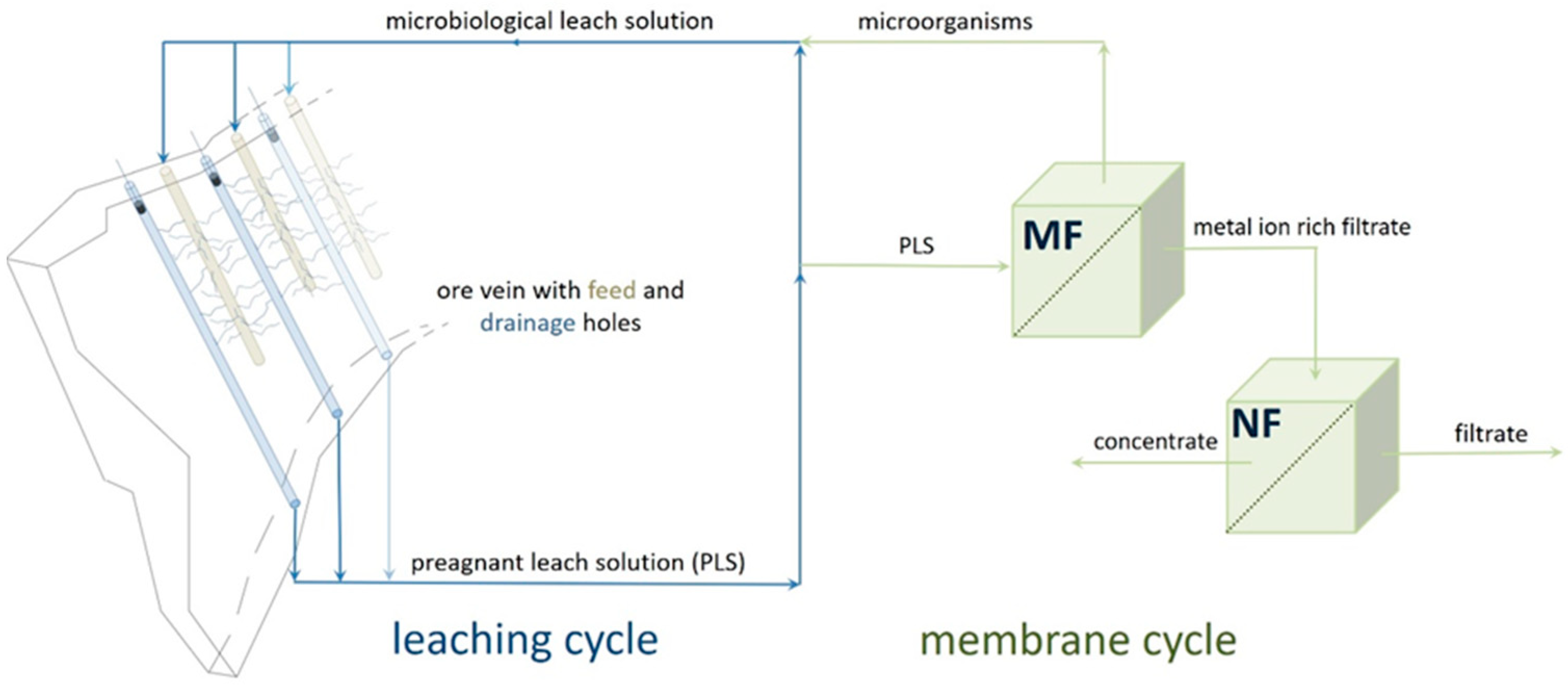
For this purpose, a pilot plant combining in-situ extraction with on-site membrane technology was installed in the research mine Reiche Zeche in Freiberg, Germany. The schematic flow diagram is shown in Figure 1.
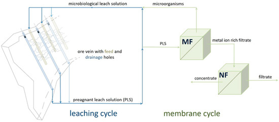
Figure 1.
Schematic process flow of leaching and downstream processing (MF: microfiltration; NF: nanofiltration) at research mine Reiche Zeche Freiberg, Germany.
The extraction by a microbial leach solution dissolves the strategic elements, in the present case from sulphide ores—in the form of ions—while permeating through a pre-fracked ore vein from the upper feed level to the lower level [3]. The resulting pregnant leach solution (PLS) is rich in the target ions and mostly sulphate anions, which are another product of the microbial catalyzed redox-reaction-based dissolution process. For more general information on the process of bioleaching, see these references [8,10,12]. The leaching feed solution, containing microorganisms, was cultured on site from locally occurring AMD (acid mine drainage), which is characterized by a highly diverse composition of different microorganisms. Dominant and, for the bioleaching, relevant taxa include Leptospirillum, Acidithiobacillus, and Ferrovum [13]. The most common minerals of the subject ore vein “Wilhelm Stehender” are galena, pyrite, sphalerite, arsenopyrite, and chalcopyrite [14].
At defined time intervals (2–4 weeks) or when the metal ion concentration stagnated (verified by ICP-MS measurements), the leaching ended and a two-stage membrane filtration process, involving micro- and nanofiltration, as a first downstream processing followed.
This manuscript aims at characterizing the membrane separation of germanium and indium contained in the PLS via a hybrid membrane plant, installed on site 147 m under the surface in the research mine Reiche Zeche in Freiberg, Germany. According to the EU Commission Study on critical raw materials, both target compounds belong to the elements of increasing interest [1]. Preparatory experiments on permeance and ion retention carried out at a laboratory scale are also reported.
2. Materials and Methods
2.1. Laboratory Scale Setup
Laboratory experiments were carried out with the crossflow membrane system, shown in Figure 2.
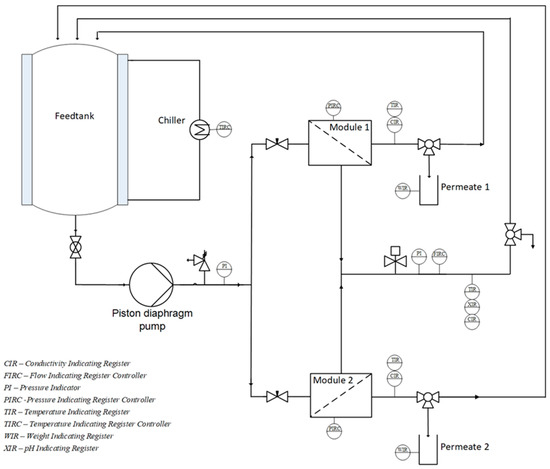
Figure 2.
Flowchart of the laboratory crossflow membrane system.
A piston diaphragm pump (Verder, Type G03, Haan, Germany) conveys the feed with a maximum membrane overflow velocity of 1.5 m s−1 in a pressure range up to 25 bars. The system features two membrane cells with an active membrane surface area of 76 cm2 each. Permeate flows are measured gravimetrically. In addition, sensors for temperature, retentate volume flow, conductivity, and pH value are implemented. More information can be found in [15].
2.2. Pilot Scale Setup
Figure 3 shows the underground hybrid membrane plant with its required compact design, built by Andreas Junghans® GmbH & Co. KG (Frankenberg, Germany).
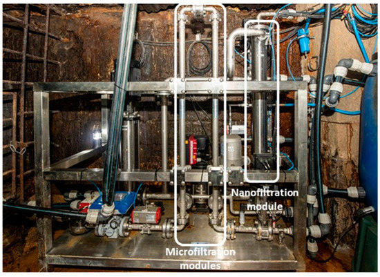
Figure 3.
Membrane pilot plant at research mine Reiche Zeche.
All components for the membrane pilot plant device have been selected according to the material stressing environmental conditions of almost 100% humidity, 11 °C, as well as the sulfuric acid feed solution (pH ≤ 2). The pilot plant consists of 2 cycles—a microfiltration and a nanofiltration cycle—as shown in Figure 4.
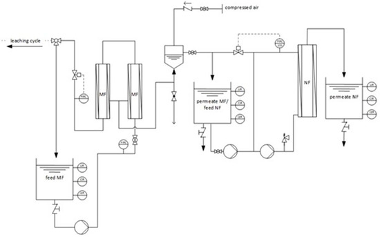
Figure 4.
Flow sheet of the membrane pilot plant.
The microfiltration cycle features 2 microfiltration modules connected in series as well as a permeate backwash unit. Within the microfiltration cycle, the overflow velocity cannot be adjusted via the installed pump. Therefore, higher system pressures result in lower overflow velocities of approximately 3.4 m s−1 at 3 bar, 4.5 m s−1 at 2 bar, and 5.9 m s−1 at 1 bar. The nanofiltration cycle follows the microfiltration and is equipped with a feed pump (Grundfos CRN1-33, Bjerringbro, Denmark) and a recirculation pump (Grundfos CRNE5-4, Bjerringbro, Denmark) as well as one membrane module housing a spiral wound membrane. The nanofiltration membrane is overflown up to 1.1 m s−1 at transmembrane pressure differences () up to 25 bars. All tanks are equipped with sensors for pH, redox, temperature, and conductivity, as well as a sensor for recording the hydrostatic pressure.
2.3. Membranes
Two thin-film composite polyamide nanofiltration membranes, NF99 and NF99HF (© Alfa Laval Corporate AB, Glinde, Germany), which are specified in Table 1, were characterized and compared during the preparative lab-tests.

Table 1.
Membrane specifications.
Based on the lab tests, membrane NF99 in the form of a spiral wound membrane with an active surface area of 7.047 m2 was used in the pilot plant. The microfiltration cycle is equipped with 2 ceramic α-Al2O3 membranes from inopor®micro (Scheßlitz, Germany) with a cut-off of 200 nm, 61 channels and an active membrane surface of 0.512 m2 each.
2.4. Feed Solutions
For analyzing the membrane permeance and ion retention, various feed solutions were considered, which are compiled in Table 2.
Table 2.
Feed solutions.
For the lab experiments, deionized water (DI) and PLSDI (based on deionized water) were used. The ion composition of PLSDI was set to mimic real PLS according to [4] (see Table 3).
Table 3.
Element composition of synthesized PLS.
Due to its availability, MTW (characterized by a large number of ions, particles, and microorganisms) had to be used instead of DI, when upscaling the laboratory experiments to pilot scale. In order to identify changes in membrane performance, PLSMTW was gradually supplemented with PLS100 to PLS25 and PLS50 during the pilot-scale experiments. Essential characteristics of the used feed solutions can be found in Table 4.
Table 4.
Essential feed solution characteristics.
2.5. Membrane Characterization
The permeance
is the permeated volume flow relative to the membrane surface area and pressure difference between feed and permeate side of the membrane. The retention
is calculated compound-specifically from the ratio between the concentration of the compound in the feed and in the permeate [19]. The recovery rate
is the ratio of feed volume to the accumulated permeate volume . The selectivity
describes the retention of a compound relative to compound .
2.6. Test Procedure
The laboratory experiments were performed for the membranes NF99 and NF99HF with DI and PLSDI at different pressures (10–5–20 bar) and overflow velocities (0.5–1.25 m s−1) at 25 °C for at least three times with a set of two membranes each (see crossflow membrane system design Figure 2). Consequently, the shown results, originating from a minimum of six values, are calculated as mean values
with representing the number of measured values . Error bars will represent the root-mean-square deviation of the results according to
Tests at the underground membrane pilot plant were carried out at least twice due to the limited availability of real leaching solution (PLS100/PLS50/PLS25). The pressure range for MF was 1 to 3 bars and for NF 7.5 to 20 bars with an overflow velocity of 1.1 m s−1. Sampling was performed at an RR of 80% unless otherwise stated.
3. Results
3.1. Preparatory Lab Experiments
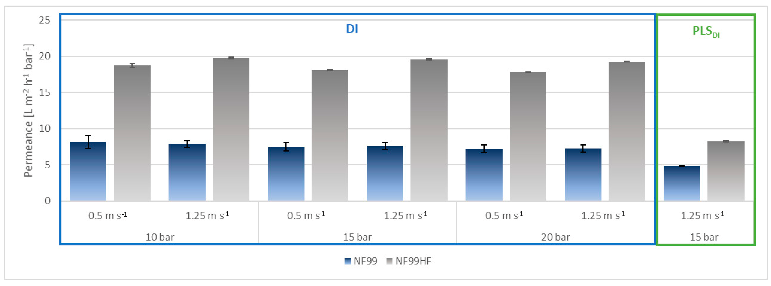
The essential aim of the laboratory experiments was to compare the NF99 membrane to NF99HF, used in previous studies [4], with respect to their permeance and separation behavior. Figure 5 compares the lab results for the permeance of these two membranes for deionized water (DI) at different pressures (10–15–20 bar) and overflow velocities (0.5–1.25 m s−1) at 25 °C. Furthermore, the permeance using PLSDI at selected process conditions of 1.25 m s−1 and 15 bars is shown.
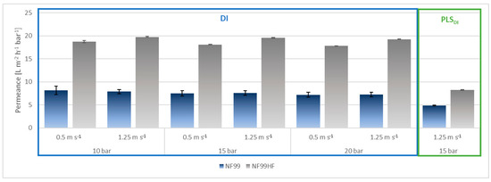
Figure 5.
Average permeance for NF99 (blue) and NF99HF (grey) for DI and PLSDI as function of pressure and overflow velocity.
For both membranes, the resulting DI permeance decreases with increasing pressure marginally at a fixed overflow velocity of 0.5 m s−1 or 1.25 m s−1, whereby all results are in good agreement with the values published in [4] (NF99: 10 L m−2 h−1 bar−1; NF99HF: 9–18 L m−2 h−1 bar−1). For NF99, a drop in permeance of 12.1% at an overflow velocity of 0.5 m s−1 from 10 to 20 bar and of 8.1% at an overflow velocity of 1.25 m s−1, also from 10 to 20 bar, can be found. For NF99HF, the permeance drops by 5.1% at 0.5 m s−1 and 2.5% at 1.25 m s−1 with increasing pressure from 10 to 20 bar. According to [20,21], the permeance of DI should be independent of the transmembrane pressure. The cause of the drop in permeance with increasing pressure could be due to compaction effects, although all membranes have been conditioned at 15 bar [22].
NF99HF consistently exhibits a higher DI permeance than NF99. As a consequence of electrostatic interactions between the ions of the feed solution and the charged membrane surface, a significant drop in permeance is observed for NF99 and NF99HF, from 36% to 58%, respectively, when replacing DI by PLSDI.
It can be noted that the root-mean-square deviation is generally lower for the NF99HF than for NF99. Since both membranes have undergone exactly the same pre-treatment, it can be concluded that the uniformity of the membrane surface for NF99HF might be higher than NF99. Nevertheless, it should also be considered that due to the relatively small membrane surface area, even the smallest process- and manufacturing-related changes in membrane structure can have an effect on the resulting flux and permeance.
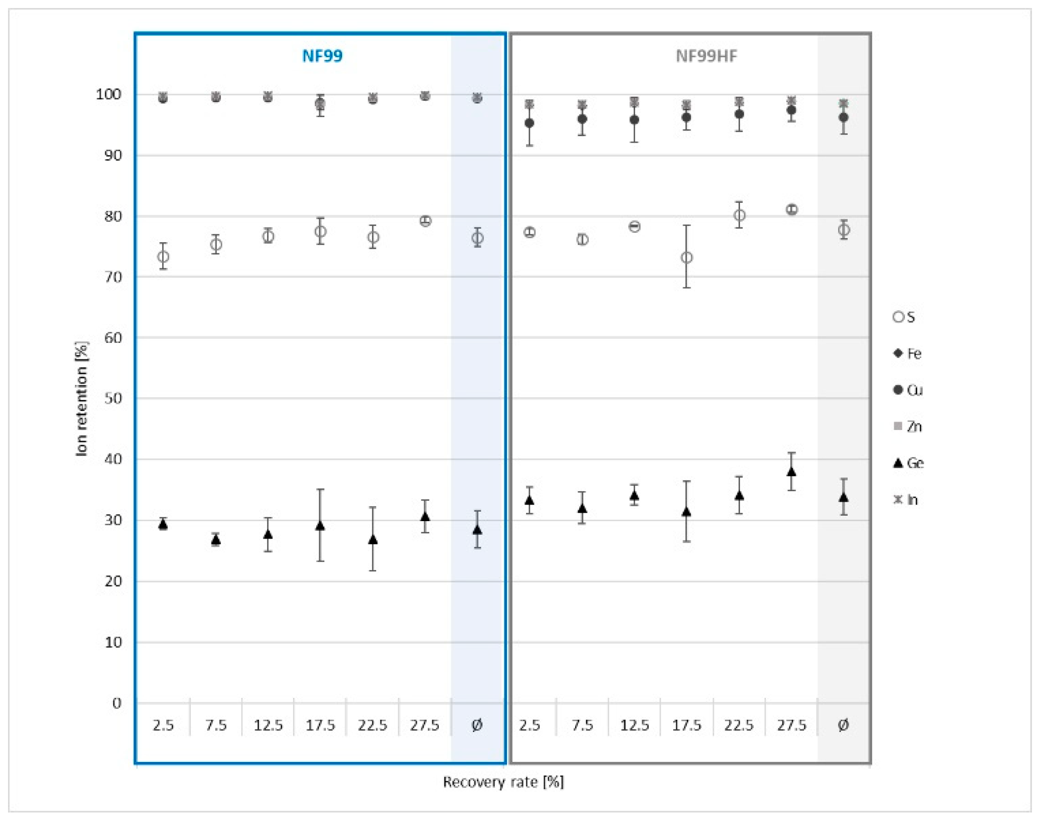
Additional consideration of ion-specific retention as a function of the recovery rate (see Figure 6) reveals further differences between both tested membranes.
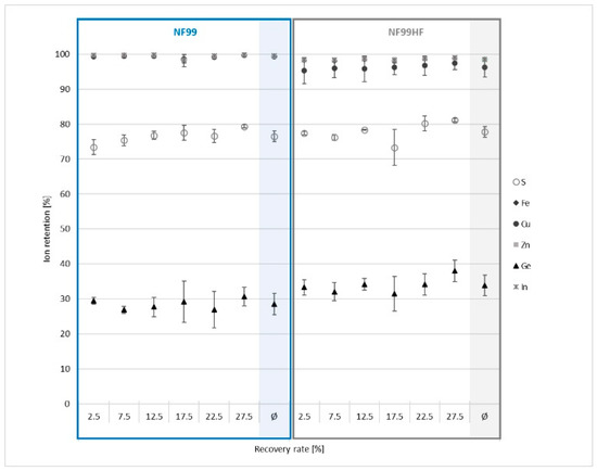
Figure 6.
Ion retention for NF99 and NF99HF for PLSDI (15 bar, 1.25 m s−1, 25 °C).
For both membranes, ion-specific retention as a function of the recovery rate [%] shows a slight upward trend, especially for sulfur (as sulfate) and germanium. For the multivalent cations iron (Fe2+), zinc (Zn2+), and copper (Cu2+), the changes are minimal. For NF99 in particular, the cation retention is consistently above 98%. For NF99HF, only the cation Cu2+ has an average retention below 96%. This may also be due to the specific hydrated size, which, according to [23], is less than that of Zn2+ and Fe2+. The observed retention behavior goes hand in hand with the statement made in [24], which indicated that NF99 has a higher selectivity towards multivalent cations compared to NF99HF.
Clearer differences are observed for sulfur and germanium. For germanium, in the course of a selective separation between the target elements indium and germanium, it should be noted that NF99 shows an overall 5% lower retention to germanium than NF99HF. With reference to [25], at pH 2, germanium exists exclusively as neutrally charged Ge(OH)4 in aqueous solutions. Therefore, it can be assumed that the retention is not caused by the interaction of ionic charge with membrane surface charge, but by size exclusion. This leads to the conclusion that the NF99HF membrane has a more “open structure” than the NF99, which also results in the observed higher membrane permeance.
Based on the results of the ion-specific retention, NF99 was chosen for the pilot studies, despite the higher permeance of NF99HF, since the selective separation of the target elements and thus the permeate quality can be considered to be slightly higher for this specific application.
3.2. Pilot-Scale Studies
3.2.1. Microfiltration
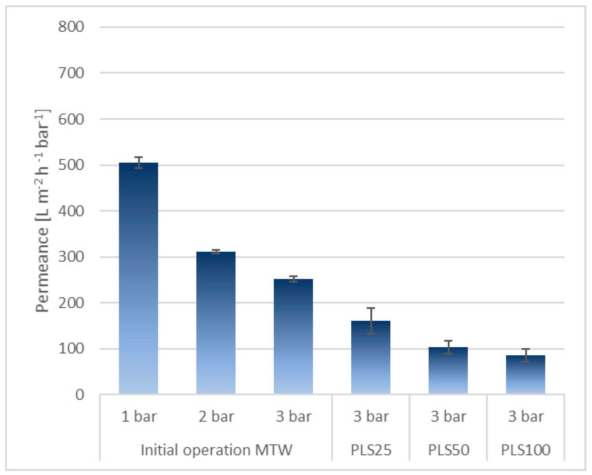
Comprehensive performance experiments for micro- and nanofiltration as a function of feed solution, pressure, and overflow velocity has been carried out. The permeance behavior for microfiltration is given in Figure 7.
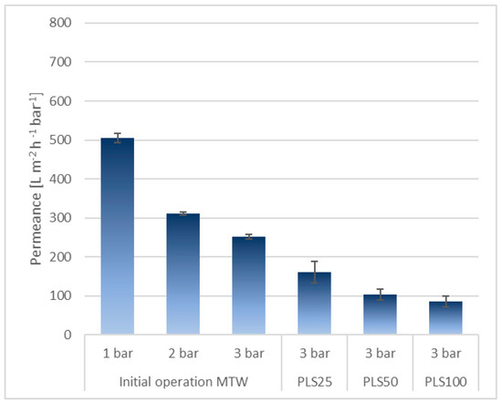
Figure 7.
Initial operation permeance for MF at 1–2–3 bar with MTW, PLS25, PLS50, and PLS100 at 3 bar, 12 °C.
The results show that, depending on the pressure, high permeances can be realized with small root-mean-square deviation. It is also evident that permeance decreases visibly as the particulate content increases from PLS25 to PLS100. Compared with MTW, the permeance of PLS100 is 66.1% lower at 3 bar, despite periodic back flushing. The main causes are seen in filter cake formation and fouling effects, which both increase the permeance resistance. Irreversible fouling can neither be removed by back-washing nor by chemical cleaning [26]. The filtration of MTW already shows a clear decrease in permeance as a result of fouling effects, which are further intensified by the decreasing overflow velocity with increasing pressure (see: Materials and Set Up—Pilot Scale).
However, despite the permeance decrease, the permeate quality remains constant as measured by the turbidity (FNU—Formazin Nephelometric Units) with a reduction between the feed and permeate by an average of 80.1% for MTW and ≥98.8% for PLS25, PLS50, and PLS100, resulting in a permeate FNU ≤ 1.
3.2.2. Nanofiltration
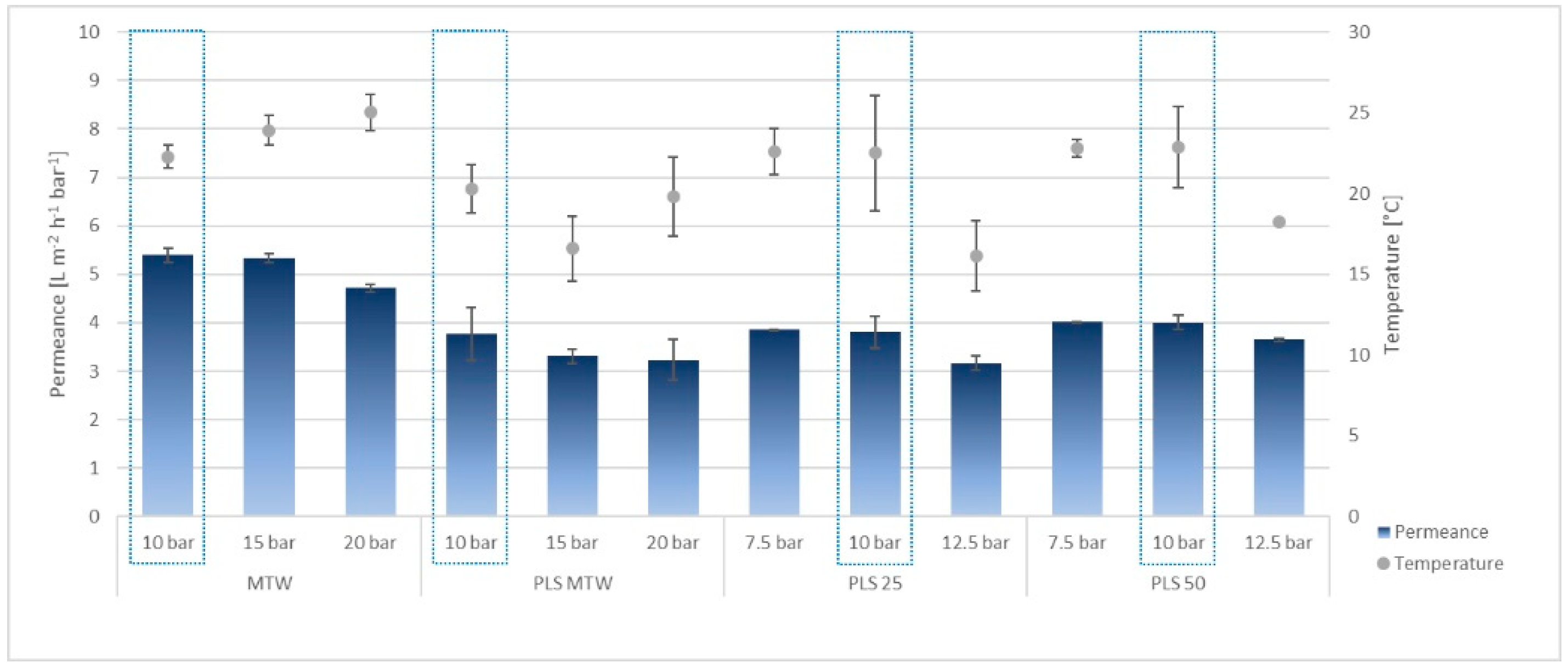
The results of the NF performance experiments using the underground membrane pilot plant are shown in Figure 8 as a function of the feed solution and pressure at an overflow velocity of 1.1 m s−1 and a recovery rate of 80%. Since the temperature of the feed solution is not adjustable at the on-site pilot plant membrane system, the temperatures are shown as well.

Figure 8.
NF permeance for MWT, PLSMTW, PLS25, and PLS50 depending on pressure and temperature.
Regarding nanofiltration, a decrease in permeance is observed as a result of increasing the system pressure. The ions present in the feed solution generate transport resistances due to their interaction with the membrane surface. These are increased with increasing pressure due to the reduction in thickness of the boundary layer and thus increase in the ion concentration directly above the membrane surface [27,28]. Furthermore, based on the conductivity, there is an increase in ion concentration from MTW to PLSMTW/PLS25/PLS50 by a factor of about 4.5, as shown in Table 4. The higher the pressure, the greater the influence of the osmotic pressure, which results in a reduction in permeance. This phenomenon is also observed and discussed by [29,30,31,32,33]. Moreover, at high pressures, the effects of concentration polarization, reversible and irreversible fouling, and diffusive transport back into the feed bulk becomes more important [34]. It can be also observed that the proportions of the solution composition of PLSMTW and PLS50 has no significant effect on permeance (cf. blue framed: PLSMTW–PLS25–PLS50 at 10 bar). The effects resulting from the variation in solution composition are determined by the change in ion composition and depend on the quality of the microfiltration. ICP-MS analyses showed that the ion composition changes only slightly by adding PLS100 to PLSMTW; the main components and concentration ratios of, e.g., Zn, Cu, Fe, Na, and S, remain relatively stable. Consequently, the constant in permeance for PLSMTW, PLS25, and PLS50 also reflects the consistently high quality of the microfiltration as a pretreatment step for the nanofiltration stage. Otherwise, a permeance drop due to fouling effects would be expected, especially for PLS50, because of the higher particulate feed-load.
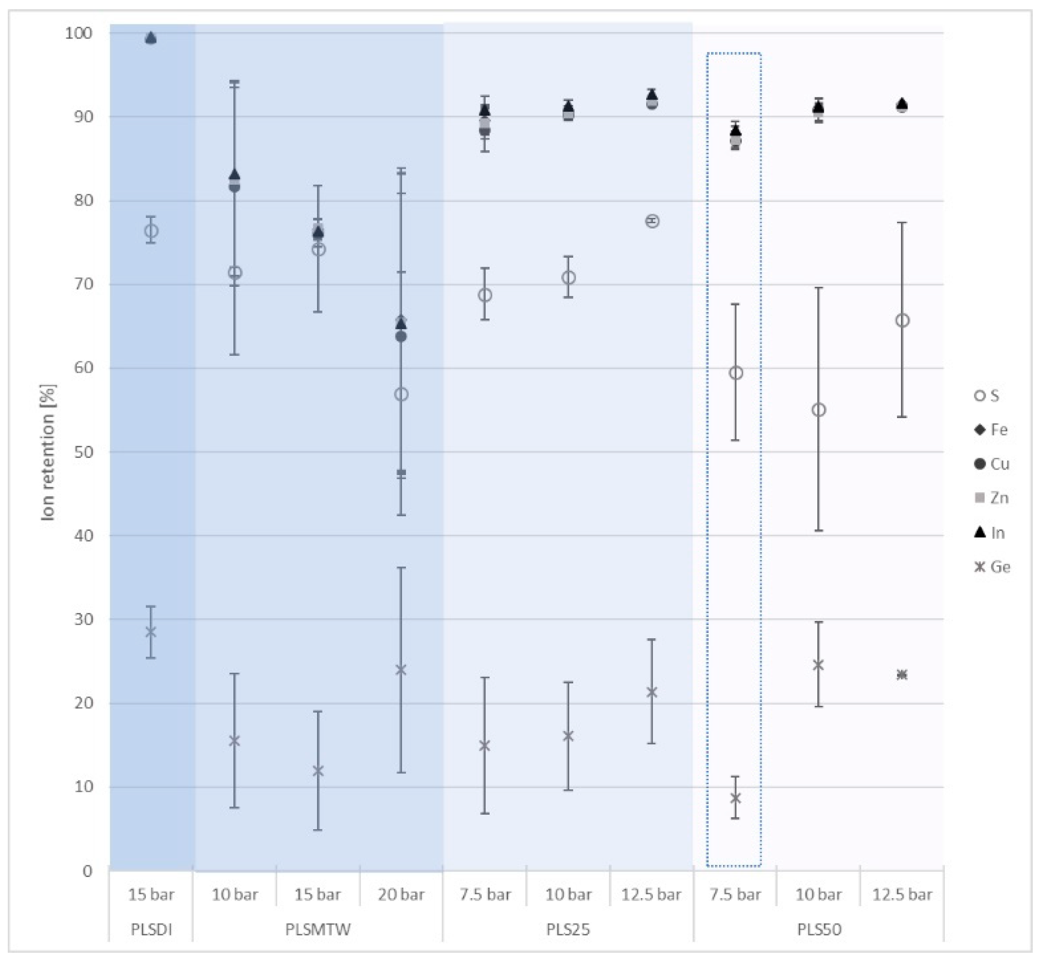
In addition to the permeance tests, the retention of characteristic elements for PLSMTW, PLS25, and PLS50 at different pressures and a fixed overflow velocity of 1.1 m s−1 was investigated. The results are shown comparatively with the results from the laboratory test (PLSDI) in Figure 9.
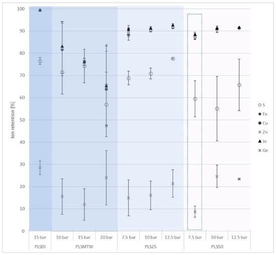
Figure 9.
Pressure dependent ion retention for PLSDI, PLSMTW, PLS25, and PLS50 depending on pressure at 1.1 m s−1 overflow velocity.
In the laboratory studies (PLSDI), an average retention of 28% was determined for Ge, whereas the multivalent cations Fe2+, Cu2+, Zn2+, and In3+ remained almost 100% in the retentate. For the on-site application (PLSMTW), a lower overall retention could be observed. Furthermore, an increased root-mean-square deviation is noticeable as well as a decreasing retention depending on the pressure. One reason for this effect is based on the test configuration. The results of the PLSMTW came from a total of four test blocks with intermediary cleaning cycles with nanofiltrated MTW at low pressures and high overflow velocities. By observing the course of ion retention within each test block, a general decrease is notable. Cleaning between the test blocks achieves a certain increase in retention but does not compensate for the overall downward trend. Therefore, fouling and scaling on the membrane surface can be assumed, leading to shielding effects due to the increase in salt concentration on the membrane surface and to a decrease in membrane repulsion. The authors of [35] came to the same conclusion within concentration-dependent performance tests for NF membranes. To ensure a more constant process performance, cleaning cycles with citric acid and caustic soda were implemented between each test block for PLS25 and PLS50. The results shown in Figure 9 indicate a more constant retention behavior, especially for the cations, with a slight upward trend due to increasing pressure. Furthermore, there is a positive influence on the selectivity with respect to indium and germanium, which was the highest at the lowest pressure (blue framed). The authors of [31] also observed an overall increase in ion retention with increasing pressure up to 15 bar using NF for copper AMD (acid mine drainage) filtration. Above 15 bars, the retention decreased again, probably due to the increased driving force for ion flow by an increase in concentration polarization. Similar results have been obtained in [34].
4. Conclusions
The laboratory experiments comparing the NF99 and NF99HF with respect to the aim of selective separation of indium and germanium from bioleaching solutions showed, for NF99, a higher selectivity, although the permeance was lower. In contrast to NF99HF, the permeance of NF99 decreased by 36% with increasing ionic concentration and complexity (from DI to PLSDI), whereas a decrease of 58% was observed for NF99HF. As a result, NF99 was chosen for the upscale of the laboratory experiments to pilot scale.
The pilot-scale experiments were carried out at a hybrid membrane plant installed 147 m underground, which serves as a first treatment step for in-situ-derived bioleaching solutions. Depending on the feed solution and the particulate and microbiological load, microfiltration showed a drop in permeance of up to 66% from MTW to PLS100 under same process conditions (3 bar, 12 °C). Despite the drop in permeance, the permeate quality was consistently high (<1 FNU). For nanofiltration, comprehensive tests under varying process conditions (pressure: 7.5–20 bars; overflow velocity: 0.5–1.1 m s−1) and for different feed solutions (MTW, PLSMTW, PLS25, PLS50) were carried out. No significant decrease in permeance from PLSMTW to PLS25 to PLS50 could be detected, which also indicates the constant high quality of pre-treatment by microfiltration. Compared to the laboratory-scale experiments (PLSDI), the ion retention of PLSMTW, PLS25, and PLS50 also showed comparable performance. The best selectivity of 11 between indium and germanium was at low pressures (7.5 bar) and the maximum overflow velocity (1.1 m s−1) for PLS50 and increased compared to the laboratory experiments (PLSDI). Overall, the laboratory experiments were successfully transferred to pilot scale (TRL6). Furthermore, the underground-installed hybrid membrane system is characterized by its functionality and long-term stability.
With reference to economic aspects, membrane technology shows a clear energy advantage over other processes. For example, in seawater desalination, membrane technology is dominating almost completely in the field of newly constructed facilities. Compared to standard thermal processes, the total electrical energy equivalent is only around 30–50%. Of course, this cannot be transferred directly to the recovery of strategic elements, wherein the extraction processes or ion exchange are efficiently working state-of-the-art technologies. In contrast to membrane technology, these technologies involve large quantities of chemicals. Furthermore, current membrane systems have long endurance in terms of stability and separation quality and energy consumption can be further reduced by incorporating energy recovering systems. Especially in fluid systems with very large concentration differences (such as in the present system), it must be emphasized that the step towards sustainable downstream processing can be achieved through a hybrid interconnection of the various separation processes. For final economic evaluation of membrane processes for strategic element recovery, further long-term studies must be carried out [36,37].
Author Contributions
Conceptualization, K.G.; methodology, K.G. and R.H.; validation, K.G. and R.H.; formal analysis, K.G.; investigation, K.G.; data curation, K.G.; writing—original draft preparation, K.G.; writing—review and editing, K.G. and A.S.B. and R.H.; visualization, K.G.; supervision, A.S.B. and R.H.; project administration, R.H.; funding acquisition, R.H. and A.S.B. All authors have read and agreed to the published version of the manuscript.
Funding
This research was funded by the AUDI Environmental Foundation, grand number 040302084B.
Acknowledgments
The authors would like to thank the AUDI Environmental Foundation for financial support.
Conflicts of Interest
The authors declare no conflict of interest.
References
- European Commission. Study on the EU’s List of Critical Raw Materials (2020). Factsheets on Critical Raw Materials; European Commission: Brussels, Belgium, 2020. [Google Scholar] [CrossRef]
- ProcessNet; Verein Deutscher Ingenieure; Deutsche Gesellschaft für Chemisches Apparatewesen, Chemische Technik und Biotechnologie. Anorganische Rohstoffe—Sicherung der Rohstoffbasis von morgen. Positionspapier des Temporären ProcessNet-Arbeitskreises “Rohstoffe und Kreislaufwirtschaft”; DECHEMA: Frankfurt am Main, Germany, 2015; ISBN 978-3-89746-177-2. [Google Scholar]
- Schlüter, R.; Mischo, H. In-situ underground bioleaching—Novel conditioning technologies. In Mining: Navigating the Global Waters, Proceedings of the 2015 SME Annual Conference & Expo and CMA 117th National Western Mining Conference, Denver, CO, USA, 15–18 February 2015; Society for Mining, Metallurgy, and Exploration; Colorado Mining Association: Denver, CO, USA, 2015; pp. 299–303. ISBN 978-151-080-124-0. [Google Scholar]
- Werner, A. Entwicklung eines Membranbasierten Trenn- und Anreicherungsverfahrens zur Selektiven Gewinnung von Indium und Germanium aus Laugungslösungen. Ph.D. Thesis, TU Bergakademie Freiberg, Freiberg, Germany, 13 August 2018. [Google Scholar] [CrossRef]
- Werner, A.; Haseneder, R.; Repke, J.-U. Design and Conception of a Membrane Pilot Plant for the In Situ Treatment of Bioleaching Solutions. Chem. Ing. Tech. 2019, 91, 145–150. [Google Scholar] [CrossRef] [Green Version]
- Meschke, K. Selective separation of strategic elements germanium and rhenium from multicomponent leaching solutions by nanofiltration. Ph.D. Thesis, TU Berlin, Berlin, Germany, 20 November 2020. [Google Scholar]
- Darling, P. SME Mining Engineering Handbook, 3rd ed.; Society for Mining Metallurgy and Exploration: Littleton, CO, USA, 2011; ISBN 978-0-87335-264-2. [Google Scholar]
- Bosecker, K. Bioleaching: Metal solubilization by microorganisms. FEMS Microbiol. Rev. 1997, 20, 591–604. [Google Scholar] [CrossRef]
- Pakostova, E.; Grail, B.M.; Johnson, D.B. Bio-processing of a saline, calcareous copper sulfide ore by sequential leaching. Hydrometallurgy 2018, 179, 36–43. [Google Scholar] [CrossRef]
- Zhang, R.; Hedrich, S.; Römer, F.; Goldmann, D.; Schippers, A. Bioleaching of cobalt from Cu/Co-rich sulfidic mine tailings from the polymetallic Rammelsberg mine, Germany. Hydrometallurgy 2020, 197, 105443. [Google Scholar] [CrossRef]
- Elbashier, E.; Mussa, A.; Hafiz, M.; Hawari, A. Recovery of rare earth elements from waste streams using membrane processes: An overview. Hydrometallurgy 2021, 204, 105706. [Google Scholar] [CrossRef]
- Johnson, D.B. Biomining-biotechnologies for extracting and recovering metals from ores and waste materials. Curr. Opin. Biotechnol. 2014, 30, 24–31. [Google Scholar] [CrossRef]
- Haferburg, G.; Krichler, T.; Hedrich, S. Prokaryotic communities in the historic silver mine Reiche Zeche. Extremophiles 2022, 26, 2. [Google Scholar] [CrossRef]
- Seifer, T.; Sandmann, D. Mineralogy and geochemistry of indium-bearing polymetallic vein-type deposits: Implications for host minerals from the Freiberg district, Eastern Erzgebirge, Germany. Ore Geol. Rev 2006, 28, 1–31. [Google Scholar] [CrossRef]
- Meschke, K.; Hofmann, R.; Repke, J.-U. Membrane treatment of leached mining waste- A potential process chain for the separation of the strategic elements germanium and rhenium. Chem. Eng. J. 2020, 380, 122476. [Google Scholar] [CrossRef]
- Alfa Laval Corporate, A.B. Hygienic Spiral Membranes for Nano-Filtration. Alfa Laval NF PET Series, ESE00626EN 1410. 2016. Available online: http://www.sanitaryindustry.com/products/alfalaval/spiral-membranes--nf-spiral.html (accessed on 20 December 2020).
- Restolho, J.A.; Prates, A.; de Pinho, M.N.; Afonso, M.D. Sugars and lignosulphonates recovery from eucalyptus spent sulphite liquor by membrane processes. Biomass Bioenergy 2009, 33, 1558–1566. [Google Scholar] [CrossRef]
- Afonso, M.D. Assessment of NF and RO for the potential concentration of acetic acid and furfural from the condensate of eucalyptus spent sulphite liquor. Sep. Purif. 2012, 99, 86–90. [Google Scholar] [CrossRef]
- Kelewou, H.; Lhassani, A.; Merzouki, M.; Drogui, P.; Sellamuthu, B. Salts retention by nanofiltration membranes: Physicochemical and hydrodynamic approaches and modelling. Desalination 2011, 277, 106–112. [Google Scholar] [CrossRef]
- Melin, T.; Rautenbach, R. Membranfverfahren. Grundlagen der Modul- und Anlagenauslegung, 3rd ed.; Springer: Berlin/Heidelberg, Germany, 2007; ISBN 3-540-00071-2. [Google Scholar]
- Van der Bruggen, B. Nanofiltration. In Encyclopedia of Membrane Science and Technology, 2nd ed.; Hoek, E.M.V., Tarabara, V.V., Eds.; John Wiley & Sons: Hoboken, NJ, USA, 2013. [Google Scholar] [CrossRef]
- Volkov, A. Membrane Compaction. In Encyclopedia of Membranes; Drioli, E., Giorno, L., Eds.; Springer: Berlin/Heidelberg, Germany, 2014. [Google Scholar] [CrossRef]
- Nightingale, E.R. Phenomenological Theory of Ion Solvation. Effective Radii of Hydrated Ions. J. Phys. Chem. 1959, 63, 1381–1387. [Google Scholar] [CrossRef]
- Madsen, H.T.; Søgaard, E.G. Applicability and modelling of nanofiltration and reverse osmosis for remediation of groundwater polluted with pesticides and pesticide transformation products, Sep. Purif. Technol. 2014, 125, 111–119. [Google Scholar] [CrossRef]
- Park, H.-J.; Tavlarides, L.L. Germanium(IV) adsorption from aqueous solution using a Kelex-100 functional adsorbent. Ind. Eng. Chem. Res. 2009, 48, 4014–4021. [Google Scholar] [CrossRef]
- Nguyen, A.H.; Tobiason, J.E.; Howe, K.J. Fouling indices for low pressure hollow fiber membrane performance assessment. Water Res. 2011, 45, 2627–2637. [Google Scholar] [CrossRef]
- Andrade, L.H.; Aguiar, A.O.; Pires, W.L.; Grossi, L.B.; Amaral, M.C.S. Comprehensive bench- and pilot-scale investigation of NF for gold mining effluent treatment: Membrane performance and fouling control strategies. Sep. Purif. Technol. 2017, 174, 44–56. [Google Scholar] [CrossRef]
- Afonso, M.; Pinho, M. Transport of MgSO4, MgCl2, and Na2SO4 across an amphoteric nanofiltration membrane. J. Membr. Sci. 2000, 179, 137–154. [Google Scholar] [CrossRef]
- Schipolowski, T. Experimentelle und Theoretische Untersuchungen zur Auslegung von Ultrafiltrationsverfahren. Ph.D. Thesis, TU Berlin, Berlin, Germany, 25 January 2007. [Google Scholar] [CrossRef]
- Al-Rashdi, B.A.M.; Johnson, D.J.; Hilal, N. Removal of heavy metal ions by nanofiltration. Desalination 2013, 315, 2–17. [Google Scholar] [CrossRef]
- Ambiado, K.; Bustos, C.; Schwarz, A.; Bórquez, R. Membrane technology applied to acid mine drainage from copper mining. Water Sci. Technol. 2017, 75, 705–715. [Google Scholar] [CrossRef]
- Ricci, B.C.; Ferreira, C.D.; Aguiar, A.O.; Amaral, M.C.S. Integration of nanofiltration and reverse osmosis for metal separation and sulfuric acid recovery from gold mining effluent. Sep. Purif. Technol. 2015, 154, 11–21. [Google Scholar] [CrossRef]
- Aguiar, A.O.; Andrade, L.H.; Ricci, B.C.; Pires, W.L.; Miranda, G.A.; Amaral, M.C.S. Gold acid mine drainage treatment by membrane separation processes: An evaluation of the main operational conditions. Sep. Purif. Technol. 2016, 170, 360–369. [Google Scholar] [CrossRef]
- Pino, L.; Vargas, C.; Schwarz, A.; Borquez, R. Influence of operating conditions on the removal of metals and sulfate from copper acid mine drainage by nanofiltration. Chem. Eng. J. 2018, 345, 114–125. [Google Scholar] [CrossRef]
- Teixeira, M.R.; Rosa, M.J.; Nyström, M. The role of membrane charge on nanofiltration performance. J. Membr. Sci. 2005, 265, 160–166. [Google Scholar] [CrossRef]
- Takabatake, H.; Taniguchi, M.; Kurihara, M. Advanced Technologies for Stabilization and High Performance of Seawater RO Membrane Desalination Plants. Membranes 2021, 11, 138. [Google Scholar] [CrossRef] [PubMed]
- Stillwell, A.S.; Webber, M.E. Predicting the Specific Energy Consumption of Reverse Osmosis Desalination. Water 2016, 8, 601. [Google Scholar] [CrossRef]


Publisher’s Note: MDPI stays neutral with regard to jurisdictional claims in published maps and institutional affiliations. |
© 2021 by the authors. Licensee MDPI, Basel, Switzerland. This article is an open access article distributed under the terms and conditions of the Creative Commons Attribution (CC BY) license (https://creativecommons.org/licenses/by/4.0/).