
Reconstruction of Copper Smelting Technology Based on 18–20th-Century Slag Remains from the Old Copper Basin, Poland

Abstract
1. Introduction
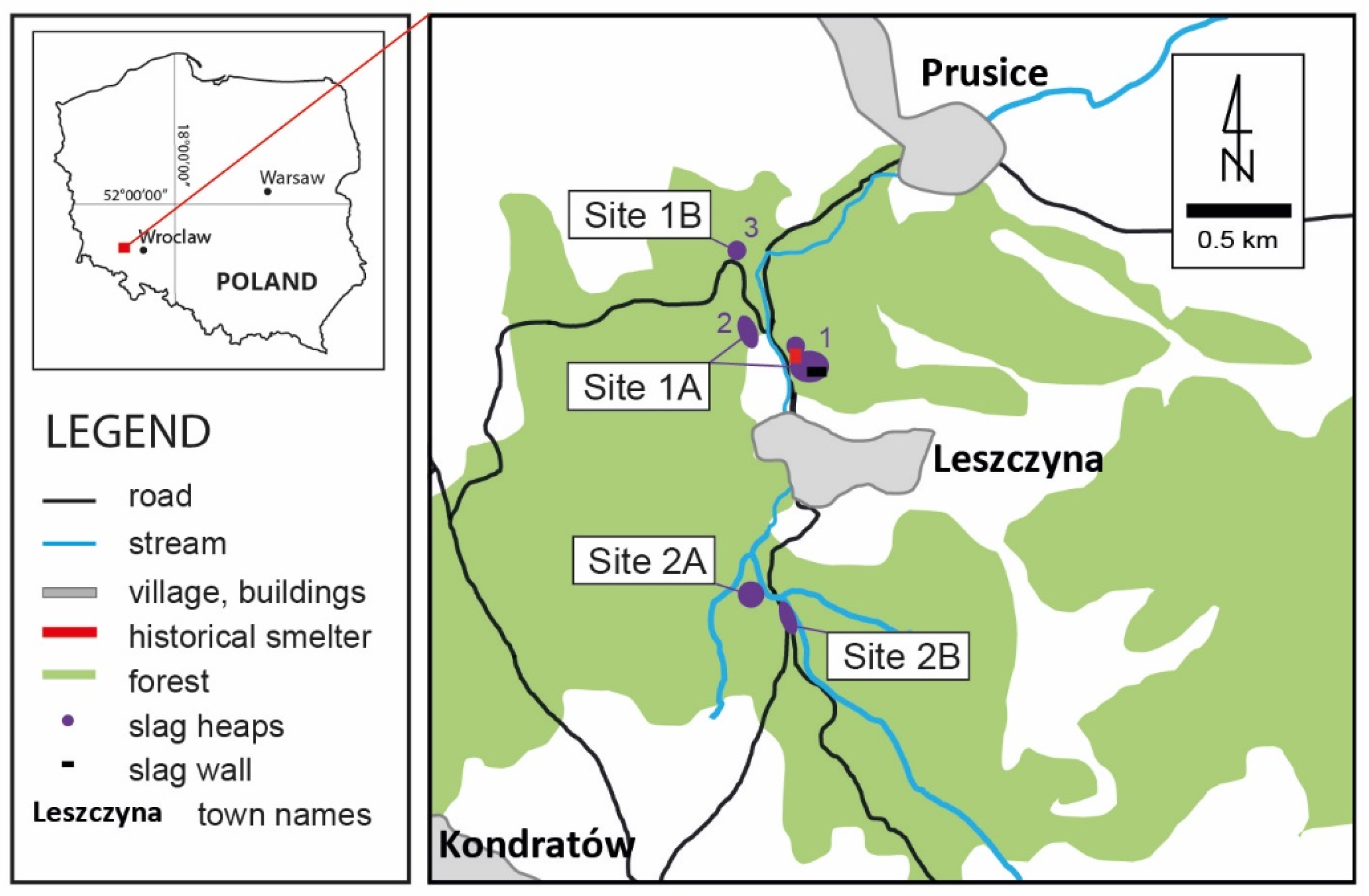
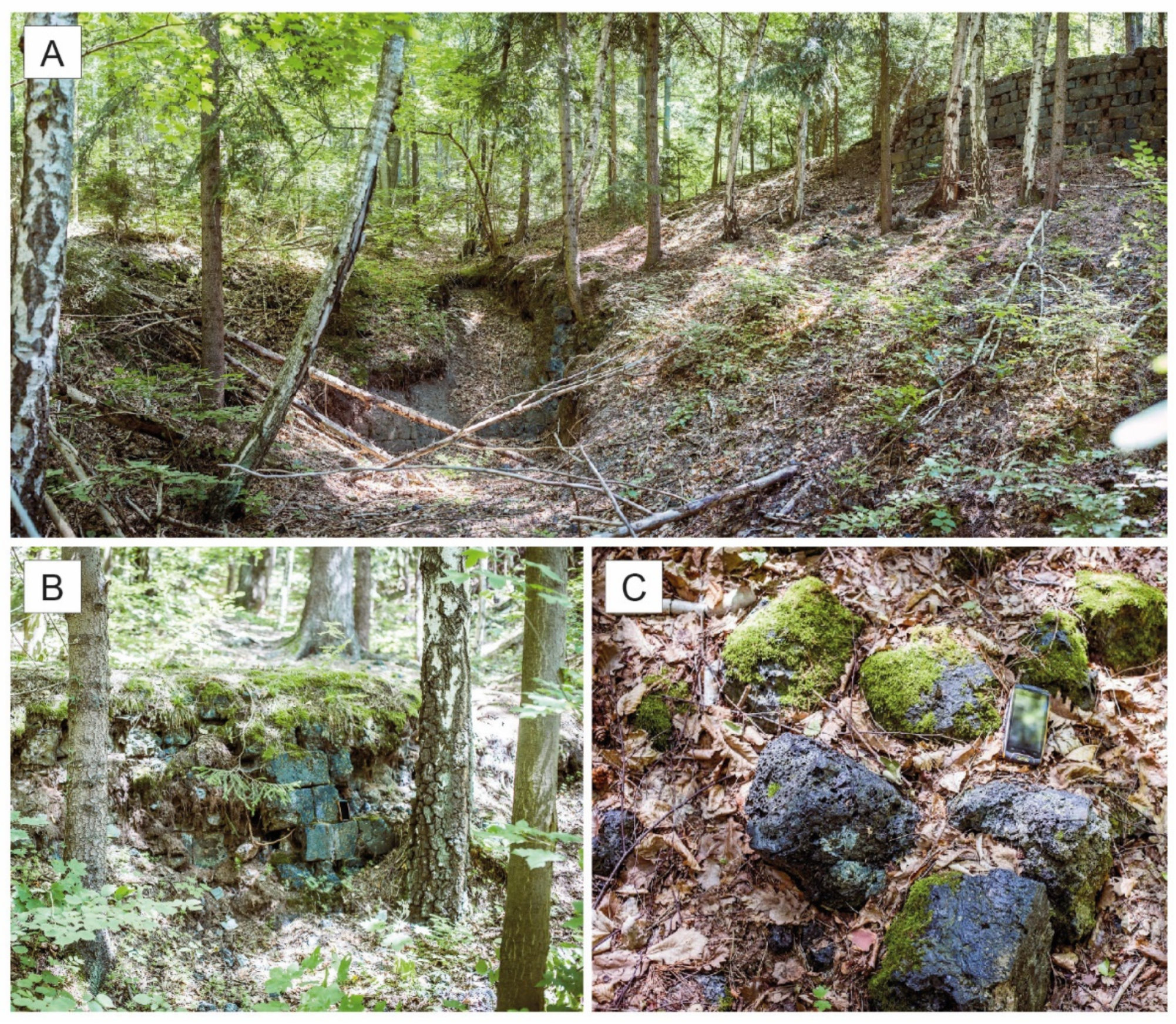
2. Site Description
2.1. Geological Setting
2.2. Historical Setting
3. Materials and Methods
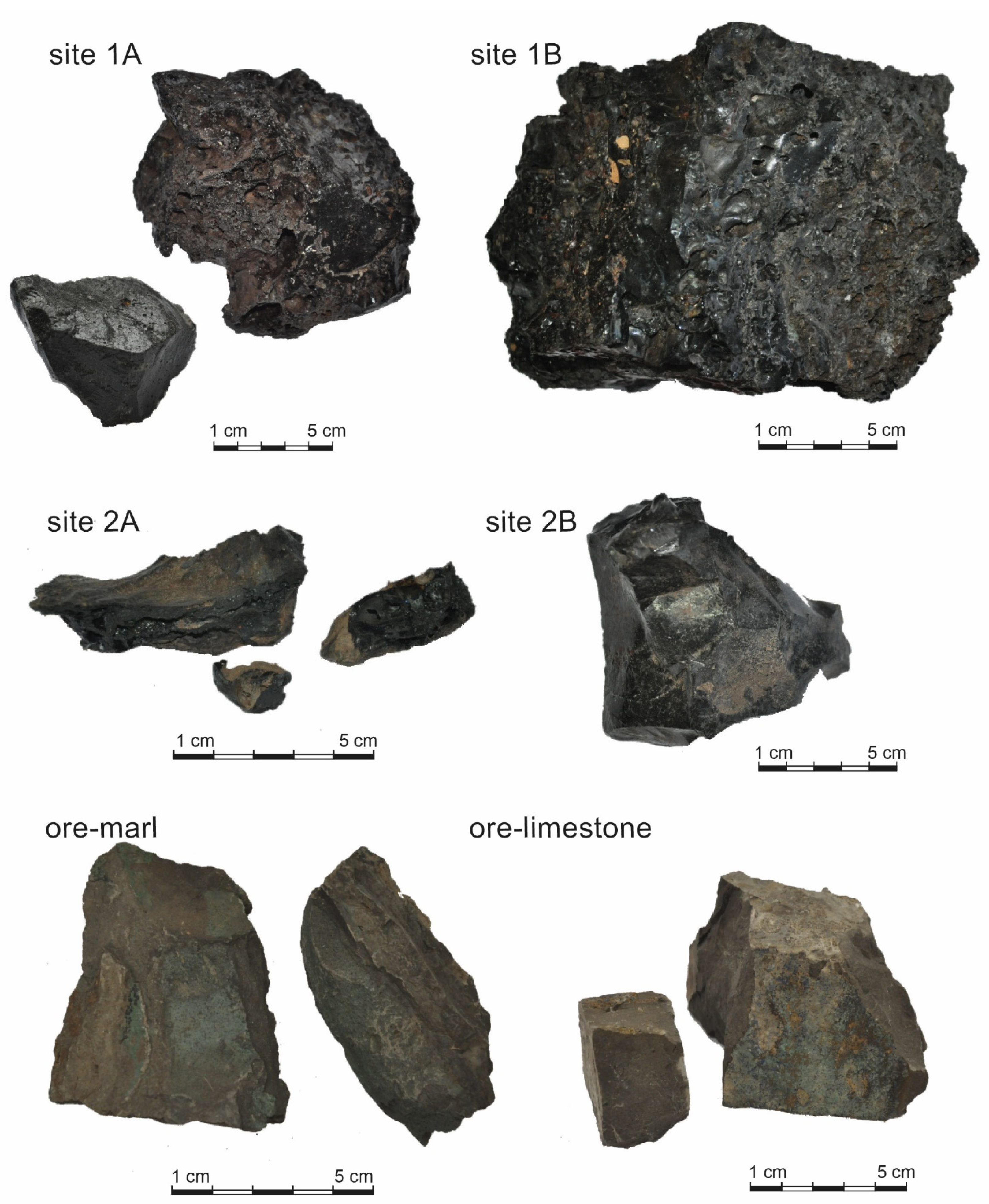
3.1. Sampling
3.2. Chemical Analyses
3.3. Mineralogical and Petrographic Analyses
4. Results
4.1. Slag Overview
4.2. Chemical Composition
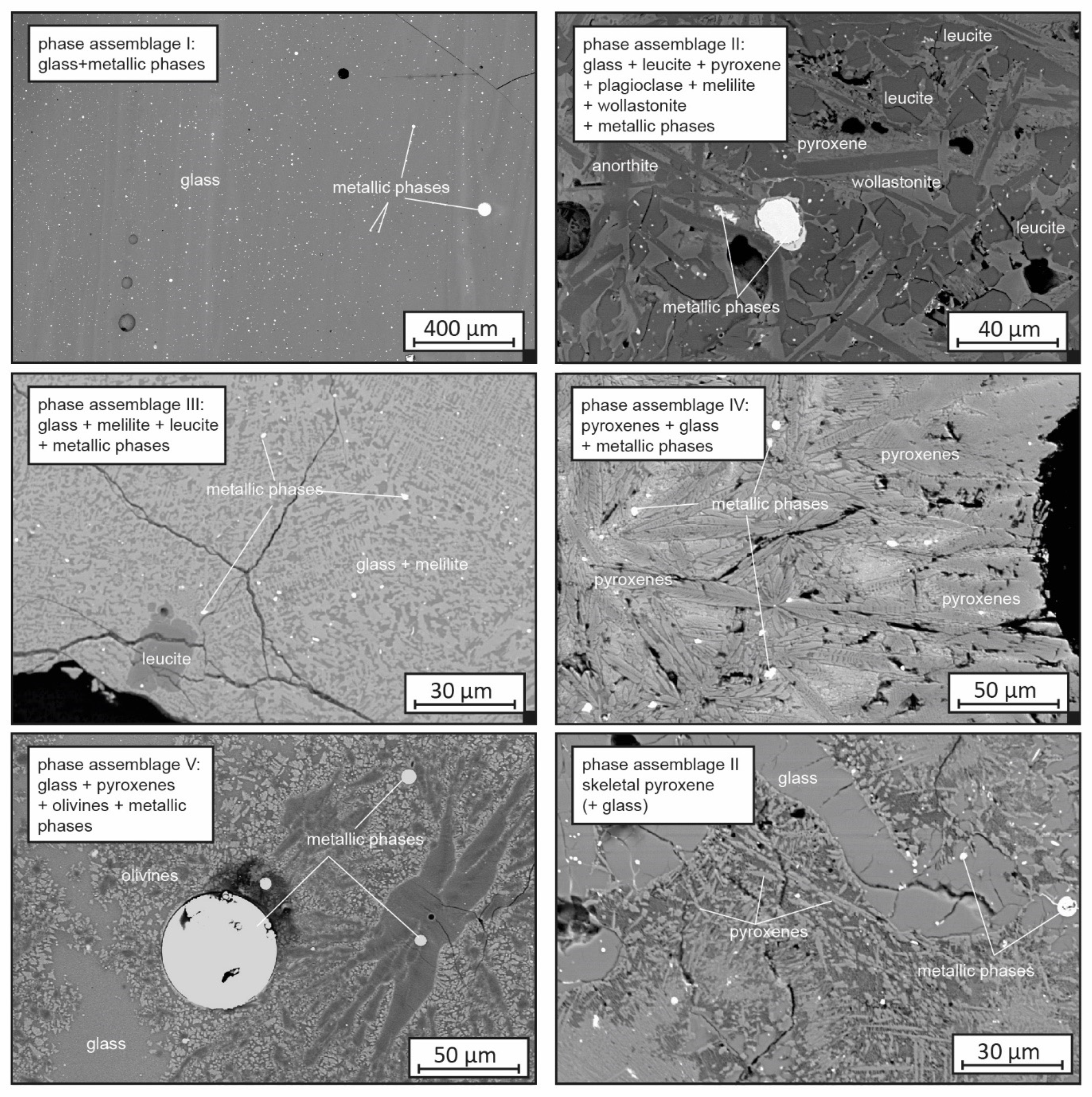
4.3. Phase Composition and Phase Chemistry
4.4. Ore-Hosting Rocks
5. Discussion
5.1. Historical Information
5.2. Furnace Input: Local Ores, Type of Flux, and Ore Roasting
5.3. Furnace Construction
5.4. Smelting Temperature
5.5. Oxygen Fugacity (Furnace Atmosphere)
5.6. Slags Viscosity and Metal Extraction Efficiency
5.7. Cooling Conditions
5.8. Amount of Slag Created
6. Conclusions
Author Contributions
Funding
Data Availability Statement
Acknowledgments
Conflicts of Interest
References
- Ettler, V.; Červinka, R.; Johan, Z. Mineralogy of medieval slags from lead and silver smelting (Bohutín, Příbram district, Czech Republic): Towards estimation of historical smelting conditions. Archaeometry 2009, 51, 987–1007. [Google Scholar] [CrossRef]
- Warchulski, R.; Szczuka, M.; Kupczak, K. Reconstruction of 16th–17th Century Lead Smelting Processes on the Basis of Slag Properties: A Case Study from Sławków, Poland. Minerals 2020, 10, 1039. [Google Scholar] [CrossRef]
- Stos-Gale, Z.A.; Gale, N.H. Metal provenancing using isotopes and the Oxford archaeological lead isotope database (OXALID). Archaeol. Anthropol. Sci. 2009, 1, 195–213. [Google Scholar] [CrossRef]
- Chiarantini, L.; Benvenuti, M.; Costagliola, P.; Fedi, M.E.; Guideri, S.; Romualdi, A. Copper production at Baratti (Populonia, southern Tuscany) in the early Etruscan period (9th–8th centuries BC). J. Archaeol. Sci. 2009, 36, 1626–1636. [Google Scholar] [CrossRef]
- Kaczmarek, W.; Rożek, R. Historia Poszukiwań i Rozpoznania Złóż rud Miedzi w “Starym Zagłębiu Miedziowym”; Zagożdżon, P.P., Madziarz, M., Eds.; Dzieje Górnictwa—Element Europejskiego Dziedzictwa Kultury: Wrocław, Polska, 2008; pp. 97–104. (In Polish) [Google Scholar]
- Potysz, A.; Kierczak, J.; Pietranik, A.; Kądziołka, K. Mineralogical, geochemical, and leaching study of historical Cu-slags issued from processing of the Zechstein formation (Old Copper Basin, southwestern Poland). Appl. Geochem. 2018, 98, 22–35. [Google Scholar] [CrossRef]
- Stolarczyk, T.; Kobylańska, M.; Kierczak, J.; Madziarz, M.; Garbacz-Klempka, A. Leszczyna. Monografia Ośrodka Górnictwa i Metalurgii rud Miedzi; Fundacja Archeologiczna Archeo: Radziechów, Polska, 2009. (In Polish) [Google Scholar]
- Festenberg-Packisch, H. Der Metallische Bergbau Niederschlesiensunter Benutzungamtlichen Quellen in Geognostischerhistorischer und Technischer Beziehung; Verlag von Moritz Perles: Vienna, Austria, 1881. [Google Scholar]
- Manasse, A.; Mellini, M.; Viti, C. The copper slags of the Capattoli Valley, Campiglia Marittima, Italy. Eur. J. Mineral. 2001, 13, 949–960. [Google Scholar] [CrossRef]
- Manasse, A.; Mellini, M. Archaeometallurgic slags from Kutná Hora. Neues Jahrb. Miner. Abh. 2002, 8, 369–384. [Google Scholar] [CrossRef]
- Manasse, A.; Mellini, M. Chemical and textural characterisation of medieval slags from the Massa Marittima smelting sites (Tuscany, Italy). J. Cult. Herit. 2002, 3, 187–198. [Google Scholar] [CrossRef]
- Bassiakos, Y.; Catapotis, M. Reconstruction of the Copper Smelting Process Based on the Analysis of Ore and Slag Samples. Hesperia Suppl. 2006, 36, 329–353. [Google Scholar]
- Kierczak, J.; Pietranik, A. Mineralogy and composition of historical Cu slags from the Rudawy Janowickie Mountains, Southwestern Poland. Can. Miner. 2011, 49, 1281–1296. [Google Scholar] [CrossRef]
- Ströbele, F.; Wenzel, T.; Kronz, A.; Hildebrandt, L.H.; Markl, G. Mineralogical and geochemical characterization of high-medieval lead–silver smelting slags from Wiesloch near Heidelberg (Germany)—An approach to process reconstruction. Archaeol. Anthrop. Sci. 2010, 2, 191–215. [Google Scholar] [CrossRef][Green Version]
- Warchulski, R.; Gawęda, A.; Kądziołka-Gaweł, M.; Szopa, K. Composition and element mobilization in pyrometallurgical slags from the Orzeł Biały smelting plant in the Bytom—Piekary Śląskie area, Poland. Miner. Mag. 2015, 79, 459–483. [Google Scholar] [CrossRef]
- Kądziołka, K.; Pietranik, A.; Kierczak, J.; Potysz, A.; Stolarczyk, T. Towards better reconstruction of smelting temperatures: Methodological review and the case of historical K-rich Cu-slags from the Old Copper Basin, Poland. J. Archaeol. Sci. 2020, 118, 105142. [Google Scholar] [CrossRef]
- Chiarantini, L.; Benvenuti, M.; Bianchi, G.; Dallai, L.; Volpi, V.; Manca, R. Medieval Pb (Cu-Ag) Smelting in the Colline Metallifere District (Tuscany, Italy): Slag Heterogeneity as a Tracer of Ore Provenance and Technological Process. Minerals 2021, 11, 97. [Google Scholar] [CrossRef]
- Hara, U.; Słowakiewicz, M.; Raczyński, P. Bryozoans (trepostomes and fenestellids) in the Zechstein Lime stone (Wuchiapingian) of the North Sudetic Ba sin (SW Poland): Palaeoecologial implications. Geol. Q. 2013, 57, 417–432. [Google Scholar] [CrossRef][Green Version]
- Oszczepalski, S.; Speczik, S.; Zieliński, K.; Chmielewski, A. The Kupferschiefer Deposits and Prospects in SW Poland: Past, Present and Future. Minerals 2019, 9, 592. [Google Scholar] [CrossRef]
- Vaughan, D.J.; Sweeney, M.; Diedel, G.F.R.; Harañczyk, C. The Kupferschiefer: An overview with an appraisal of the different types of mineralization. Econ. Geol. 1989, 84, 1003–1027. [Google Scholar] [CrossRef]
- Wodzicki, A.; Piestrzyński, A. An ore genetic model for the Lubin-Sieroszowice mining district, Poland. Miner. Depos. 1994, 29, 30–43. [Google Scholar] [CrossRef]
- Blundell, D.J.; Karnkowski, P.H.; Alderton, D.H.M.; Oszczepalski, S.; Kucha, H. Copper Mineralization of the Polish Kupferschiefer: A proposed basement fault-fracture system of fluid flow. Econ. Geol. 2003, 98, 1487–1495. [Google Scholar] [CrossRef]
- Kucha, H.; Pawlikowski, M. Badania genezy cechsztyńskich złóż miedzi w Polsce. Geologia 2010, 36, 513–538. [Google Scholar]
- Oszczepalski, S. Origin of the Kupferschiefer polymetallic mineralization in Poland. Miner. Depos. 1999, 34, 599–613. [Google Scholar] [CrossRef]
- Malon, A.; Tymiński, M.; Mikulski, S.Z.; Oszczepalski, S. Metal resources. In The Balance of Mineral Resources in Poland as of 31.12.2018; Szuflicki, M., Malon, A., Tymiński, M., Eds.; Państwowy Instytut Geologiczny: Warszawa, Poland, 2018; pp. 51–68. (In Polish) [Google Scholar]
- Piątek, E.; Piątek, Z. Tradycje Górnicze Ziemi Złotoryjskiej. Złotoryjskie Towarzystwo Tradycji Górniczych; Wydawnictwo Atut: Wrocław, Poland, 2004. [Google Scholar]
- Stolarczyk, T. Górnictwo rud Metali Nieżelaznych na Dolnym Śląsku od XIII do Początku XVII w. Ph.D. Thesis, Uniwersytet Wrocławski, Wrocław, Poland, 2009. (In Polish). [Google Scholar]
- Stolarczyk, T. Wyniki Badań Reliktów Dawnego Górnictwa Miedzi na Terenie Pogórza Kaczawskiego w Roku 2012; Zagożdżon, P.P., Madziarz, M., Eds.; Dzieje Górnictwa—Element Europejskiego Dziedzictwa Kultury: Wrocław, Polska, 2013; Volume 5, pp. 339–351. (In Polish) [Google Scholar]
- Kowalski, A.; Maciejak, K.; Wojewoda, J.; Kozłowski, A.; Raczyński, P. Anthropogenic changes of the “Old Copper Basin” area landscape (North-Sudetic Synclinorium) in the light of LiDAR-based geomorphometric analysis and archival data. Biul. Państw. Inst. Geol. 2017, 469, 177–200. [Google Scholar] [CrossRef]
- Kądziołka, K.; Kierczak, J.; Pietranik, A. Charakterystyka mineralogiczna faz metalicznych z miedziowych żużli hutniczych Starego Zagłębia Miedziowego. [Mineralogical characteristics of metallic phases in copper slags from the Old Copper Basin, Poland]. Prz. Geol. 2019, 67, 164–166. [Google Scholar]
- Ettler, V.; Johan, Z.; Zavrel, J.; Wallisová, M.S.; Mihaljevic, M.; Šebek, O. Slag remains from the Na Slupi site (Prague, Czech Republic): Evidence for early medieval non-ferrous metal smelting. J. Archaeol. Sci. 2015, 53, 72–83. [Google Scholar] [CrossRef]
- Rozendaal, A.; Horn, R. Textural, mineralogical and chemical characteristics of copper reverb furnace smelter slag of the Okiep Copper District, South Africa. Miner. Eng. 2013, 52, 184–190. [Google Scholar] [CrossRef]
- Toffolo, L.; Addis, A.; Martin, S.; Nimis, P.; Rottoli, M.; Godard, G. The Misérègne slag deposit (Valle d’Aosta, Western Alps, Italy): Insights into (pre-)Roman copper metallurgy. J. Archaeol. Sci. Rep. 2018, 19, 248–260. [Google Scholar] [CrossRef]
- Sulem, J.; Famin, V. Thermal decomposition of carbonates in fault zones: Slip-weakening and temperature-limiting effects. J. Geophys. Res. Solid Earth 2009, 114, B03309. [Google Scholar] [CrossRef]
- Bourgarit, D.; Mille, B.; Prange, M.; Ambert, P.; Hauptmann, A. Chalcolithic Fahlore Smelting at Cabrières: Reconstruction of Smelting Processes by Archaeometallurgical Finds. In Proceedings of the Archaeometallurgy in Europe, Milan, Italy, 24–26 September 2003; Associazione Italiana di Metallurgia: Milan, Italy, 2003; pp. 431–440. [Google Scholar]
- Sáez, R.; Nocete, F.; Nieto, J.M.; Capitán, M.Á.; Rovira, S. The extractive metallurgy of copper from Cabezo Juré, Huelva, Spain: Chemical and mineralogical study of slags dated to the third millenium B.C. Can. Miner. 2003, 41, 627–638. [Google Scholar] [CrossRef]
- Tumiati, S.; Casartelli, P.; Mambretti, A.; Martin, S. The ancient mine of servette Saint-Marcel, Val D’aosta, Western Italian Alps): A mineralogical, metallurgical and charcoal analysis of furnace slags. Archaeometry 2005, 47, 317–340. [Google Scholar] [CrossRef]
- Álvarez-Valero, A.M.; Pérez-López, R.; Nieto, J.M. Prediction of the environmental impact of modern slags: A petrological and chemical comparative study with Roman age slags. Am. Miner. 2009, 94, 1417–1427. [Google Scholar] [CrossRef]
- Pelton, A.; Stamatakis, M.G.; Kelepertzis, E.; Panagou, T. The origin and archaeometallurgy of a mixed sulphide ore for copper production on the island of Kea, Aegean Sea, Greece. Archaeometry 2015, 57, 318–343. [Google Scholar] [CrossRef]
- Warchulski, R. Zn-Pb slag crystallization: Evaluating temperature conditions on the basis of geothermometry. Eur. J. Miner. 2016, 28, 375–384. [Google Scholar] [CrossRef]
- Cabała, J.; Warchulski, R.; Rozmus, D.; Środek, D.; Szełęg, E. Pb-Rich Slags, Minerals, and Pollution Resulted from a Medieval Ag-Pb Smelting and Mining Operation in the Silesian-Cracovian Region (Southern Poland). Minerals 2020, 10, 28. [Google Scholar] [CrossRef]
- Humphris, J.; Martinón-Torres, M.; Rehren, T.; Reid, A. Variability in single smelting episodes—A pilot study using iron slag from Uganda. J. Archaeol. Sci. 2009, 36, 359–369. [Google Scholar] [CrossRef]
- Bachmann, H.G. The Identification of Slags from Archaeological Sites; Institute of Archaeology Occasional Publication: Ankara, Turkey, 1982. [Google Scholar]


| Site 1A | Site 1B | Site 2A | Site 2B | |
|---|---|---|---|---|
| n = 5 | n = 2 | n = 6 | n = 2 | |
| Glass | 47.92 | 89.47 | 52.37 | 84.72 |
| Crystalline phases | 36.29 | 8.80 | 31.17 | 9.31 |
| Pores | 13.69 | 1.40 | 16.03 | 5.85 |
| Metallic phases | 0.14 | 0.20 | 0.37 | 0.10 |
| Secondary phases | 0.38 | 0.10 | 0.12 | 0.05 |
| Site 1A (19th Century) | Site 1B (20th Century) | Site 2A (18th Century) | Site 2B (19th Century) | ||||||||||
|---|---|---|---|---|---|---|---|---|---|---|---|---|---|
| n = 10 | n = 5 | n = 7 | n = 4 | ||||||||||
| av. * | Min | Max | av. * | Min | Max | av. * | Min | Max | av. * | Min | Max | ||
| SiO2 | wt% | 47.25 | 44.28 | 49.79 | 42.69 | 42.45 | 43.24 | 46.03 | 43.84 | 48.33 | 48.08 | 46.84 | 49.02 |
| Al2O3 | 17.94 | 16.77 | 18.89 | 16.20 | 16.03 | 16.41 | 11.06 | 9.57 | 12.99 | 17.78 | 17.30 | 18.16 | |
| Fe2O3 | 3.46 | 2.57 | 6.13 | 3.80 | 3.52 | 4.01 | 15.58 | 12.02 | 21.04 | 2.77 | 2.35 | 2.96 | |
| MgO | 2.71 | 2.46 | 3.38 | 2.93 | 2.85 | 2.99 | 1.92 | 1.73 | 2.12 | 3.16 | 3.01 | 3.56 | |
| CaO | 19.09 | 17.00 | 23.20 | 26.64 | 25.84 | 27.40 | 17.19 | 13.64 | 19.30 | 20.05 | 18.58 | 22.83 | |
| Na2O | 0.23 | 0.15 | 0.36 | 0.14 | 0.14 | 0.15 | 0.20 | 0.18 | 0.22 | 0.23 | 0.21 | 0.24 | |
| K2O | 6.27 | 5.85 | 6.70 | 5.59 | 5.40 | 5.71 | 4.06 | 3.41 | 4.86 | 6.22 | 5.77 | 6.50 | |
| TiO2 | 0.79 | 0.74 | 0.83 | 0.72 | 0.71 | 0.74 | 0.55 | 0.50 | 0.61 | 0.82 | 0.79 | 0.84 | |
| P2O5 | 0.19 | 0.16 | 0.23 | 0.19 | 0.18 | 0.20 | 0.25 | 0.21 | 0.35 | 0.18 | 0.16 | 0.19 | |
| MnO | 0.17 | 0.13 | 0.22 | 0.26 | 0.25 | 0.27 | 0.57 | 0.49 | 0.65 | 0.18 | 0.17 | 0.19 | |
| Cr2O3 | 0.01 | 0.01 | 0.02 | 0.01 | 0.01 | 0.01 | 0.01 | 0.01 | 0.01 | 0.01 | 0.01 | 0.01 | |
| TOT/S | 0.42 | 0.21 | 0.93 | 0.25 | 0.21 | 0.32 | 0.09 | 0.05 | 0.19 | 0.48 | 0.30 | 0.63 | |
| Cu | mg/kg | 3573 | 1503 | 10,760 | 3688 | 2627 | 5399 | 18,934 | 7330 | 44,159 | 2207 | 1856 | 2587 |
| v.i. * | 0.49 | 0.43 | 0.58 | 0.67 | 0.65 | 0.68 | 0.69 | 0.62 | 0.75 | 0.50 | 0.47 | 0.54 | |
| Glass | ||||
|---|---|---|---|---|
| Sample | K2-3 | HL2-1 | ||
| rep. * | average | rep. * | average | |
| n = 43 | n = 141 | |||
| SiO2 | 48.55 | 49.15 | 41.10 | 41.30 |
| Al2O3 | 18.27 | 18.59 | 15.60 | 15.40 |
| TiO2 | 0.89 | 0.86 | 0.70 | 0.70 |
| FeO | 3.22 | 1.87 | 3.10 | 3.10 |
| MnO | 0.16 | 0.19 | 0.20 | 0.30 |
| MgO | 2.95 | 2.94 | 2.60 | 2.70 |
| CaO | 17.93 | 18.59 | 29.00 | 28.60 |
| CuO | 0.09 | 0.07 | 0.00 | 0.10 |
| Na2O | 0.25 | 0.23 | 0.10 | 0.10 |
| K2O | 6.14 | 6.30 | 5.30 | 5.30 |
| P2O5 | 0.15 | 0.16 | 0.20 | 0.20 |
| SUM | 98.58 | 98.95 | 98.20 | 98.00 |
| Phase | Glass | Leucite | Pyroxene | Anorthite | Wollastonite | ||||||
|---|---|---|---|---|---|---|---|---|---|---|---|
| Sample | HL1 | HK6 | K2-4 | K2-11 | HK5 | PL6-s1 | K2-11 | HL2-3 | HK5 | ||
| av. * | av. * | rep. * | av. * | rep. * | rep. * | rep. * | rep. * | rep. * | rep. * | ||
| n = 17 | n = 4 | n = 4 | |||||||||
| SiO2 | wt% | 43.50 | 49.00 | 54.42 | 55.54 | 48.55 | 40.74 | 47.30 | 44.80 | 44.82 | 49.49 |
| Al2O3 | 15.56 | 15.80 | 23.22 | 23.66 | 12.59 | 8.85 | 31.45 | 34.11 | 32.75 | 0.72 | |
| TiO2 | 1.48 | 0.70 | 0.05 | 0.08 | 2.32 | 1.02 | 0.11 | 0.07 | 0.21 | 0.19 | |
| FeO | 5.75 | 4.35 | 0.00 | 0.11 | 3.12 | 19.74 | 0.28 | 0.17 | 0.76 | 5.56 | |
| MnO | 0.28 | 0.94 | 0.04 | 0.06 | 0.17 | 0.63 | 0.00 | 0.13 | 0.01 | 0.89 | |
| MgO | 5.36 | 3.13 | 0.00 | 0.03 | 7.58 | 3.91 | 0.51 | 0.38 | 0.35 | 1.61 | |
| CaO | 25.40 | 23.10 | 0.07 | 0.27 | 20.16 | 23.25 | 17.69 | 18.72 | 18.53 | 41.03 | |
| CuO | 0.07 | 0.19 | 0.15 | 0.05 | 0.00 | 0.09 | 0.04 | 0.04 | 0.00 | 0.18 | |
| Na2O | 0.16 | 0.26 | 0.13 | 0.09 | 0.13 | 0.12 | 0.90 | 0.30 | 0.25 | 0.05 | |
| K2O | 1.38 | 1.89 | 20.78 | 20.70 | 3.94 | 0.10 | 1.51 | 0.92 | 0.82 | 0.20 | |
| P2O5 | 0.24 | 0.33 | 0.00 | 0.00 | 0.11 | 0.45 | 0.05 | 0.00 | 0.07 | 0.12 | |
| SUM | 99.18 | 99.69 | 98.86 | 100.60 | 98.64 | 98.95 | 99.82 | 99.64 | 98.57 | 100.03 | |
| Phase | Glass | Glass | Melilite | Melilite | |||||
|---|---|---|---|---|---|---|---|---|---|
| Sample | L2-6 | L2-7 | L2-6 | L2-7 | |||||
| rep. * | av. * | rep. * | av. * | rep. * | av. * | rep. * | av. * | ||
| n = 20 | n = 83 | n=7 | n = 5 | ||||||
| SiO2 | wt% | 43.62 | 43.65 | 43.85 | 43.26 | 35.70 | 36.35 | 40.27 | 39.32 |
| Al2O3 | 16.18 | 16.38 | 16.36 | 16.31 | 15.71 | 14.02 | 13.92 | 13.55 | |
| TiO2 | 0.71 | 0.84 | 0.76 | 0.75 | 0.14 | 0.33 | 0.41 | 0.83 | |
| FeO | 3.37 | 2.95 | 3.07 | 3.24 | 5.27 | 5.09 | 4.43 | 4.01 | |
| MnO | 0.25 | 0.26 | 0.27 | 0.27 | 0.40 | 0.38 | 0.43 | 0.40 | |
| MgO | 2.75 | 2.69 | 2.86 | 2.83 | 3.49 | 4.39 | 3.83 | 3.82 | |
| CaO | 27.13 | 27.07 | 26.70 | 26.64 | 38.13 | 37.44 | 35.46 | 36.03 | |
| CuO | 0.20 | 0.10 | 0.04 | 0.13 | 0.16 | 0.31 | 0.00 | 0.04 | |
| Na2O | 0.18 | 0.15 | 0.16 | 0.14 | 0.30 | 0.25 | 0.20 | 0.20 | |
| K2O | 5.34 | 5.36 | 5.43 | 5.24 | 0.57 | 1.03 | 0.89 | 0.78 | |
| P2O5 | 0.15 | 0.21 | 0.20 | 0.20 | 0.04 | 0.13 | 0.13 | 0.16 | |
| SUM | 99.67 | 99.54 | 99.65 | 98.96 | 99.90 | 99.73 | 99.98 | 99.13 | |
| SL-1 | SL-2 | PL2-R1 | PL2-R2 | SK-1 | |
|---|---|---|---|---|---|
| L * | L * | L * | L * | K * | |
| SiO2 | 7.41 | 2.97 | 25.46 | 9.98 | 24.86 |
| Al2O3 | 2.25 | 0.57 | 9.04 | 3.48 | 8.89 |
| Fe2O3 | 0.84 | 1.00 | 1.82 | 0.81 | 1.77 |
| MgO | 4.31 | 18.93 | 1.61 | 1.71 | 1.54 |
| CaO | 44.24 | 30.44 | 28.23 | 43.68 | 28.46 |
| Na2O | 0.05 | 0.02 | 0.09 | 0.06 | 0.10 |
| K2O | 0.88 | 0.13 | 3.43 | 1.35 | 3.66 |
| TiO2 | 0.10 | 0.02 | 0.41 | 0.14 | 0.38 |
| P2O5 | 0.05 | 0.02 | 0.13 | 0.06 | 0.15 |
| MnO | 0.48 | 0.88 | 0.15 | 0.34 | 0.19 |
| Cr2O3 | 0.00 | <0.002 | 0.01 | 0.00 | 0.01 |
| LOI | 38.50 | 28.20 | 45.00 | 26.10 | 37.30 |
| SUM | 99.12 | 98.20 | 99.94 | 96.55 | 98.90 |
| TOT/S | 0.29 | 0.01 | 0.41 | 0.06 | 0.04 |
| Cu | 5264 | 40 | 26,230 | 6060 | 10,400 |
| Site 1A | Site 2A | Site 2A | |
|---|---|---|---|
| rep. * | rep. * | rep. * | |
| Sample | HL1 | HK5 | K1-3 |
| SiO2 | 28.87 | 34.71 | 35.89 |
| Al2O3 | 5.42 | 2.47 | 8.50 |
| TiO2 | 14.20 | 14.07 | 0.15 |
| Fe2O3 | 26.40 | 26.88 | 30.27 |
| MnO | 0.50 | 0.49 | 1.25 |
| MgO | 8.36 | 2.99 | 0.00 |
| CaO | 15.90 | 14.02 | 17.89 |
| CuO | 0.05 | 0.42 | 0.04 |
| Na2O | 0.05 | 0.28 | 0.65 |
| K2O | 0.07 | 2.28 | 0.67 |
| P2O5 | 0.17 | 0.51 | 1.03 |
| SUM | 99.99 | 99.11 | 96.33 |
| Site 1A | Site 1B | Site 2A | Site 2B | |
|---|---|---|---|---|
| Age | 19th Century | 20th Century | 19th Century | 18th Century |
| Location | Leszczyna | Leszczyna | Kondratów | Kondratów |
| Furnace input | Ore, coke, flux: arkose sandstones, pyrite, gypsum | Ore, coke, flux: arkose sandstones, pyrite(?), gypsum(?) | Ore, coke, flux: arkose sandstones, pyrite | Ore, coke, flux: arkose sandstones, pyrite, gypsum |
| Furnace type | Shaft furnace (Mansfield-style) | Unknown | Unknown | Shaft furnace (Mansfield-style) |
| Smelting (liquidus) temperature * | ~1210 °C | ~1400 °C | ~1225 °C | ~1210 °C |
| Oxygen fugacity | Reducing with leakage; QFM | Reducing; QFM | Reducing with leakage; QFM | Reducing; QFM |
| Viscosity index | 0.52 | 0.46 | 0.50 | 0.68 |
| Metal extraction efficiency | Low | Low | Low | Low |
| Cooling conditions | Air-cooled | Air-cooled (with water cooling system?) | Air-cooled | Air-cooled (possibly with water cooling system?) |
Publisher’s Note: MDPI stays neutral with regard to jurisdictional claims in published maps and institutional affiliations. |
© 2021 by the authors. Licensee MDPI, Basel, Switzerland. This article is an open access article distributed under the terms and conditions of the Creative Commons Attribution (CC BY) license (https://creativecommons.org/licenses/by/4.0/).
Share and Cite
Derkowska, K.; Świerk, M.; Nowak, K. Reconstruction of Copper Smelting Technology Based on 18–20th-Century Slag Remains from the Old Copper Basin, Poland. Minerals 2021, 11, 926. https://doi.org/10.3390/min11090926
Derkowska K, Świerk M, Nowak K. Reconstruction of Copper Smelting Technology Based on 18–20th-Century Slag Remains from the Old Copper Basin, Poland. Minerals. 2021; 11(9):926. https://doi.org/10.3390/min11090926
Chicago/Turabian StyleDerkowska, Katarzyna, Mateusz Świerk, and Kamil Nowak. 2021. "Reconstruction of Copper Smelting Technology Based on 18–20th-Century Slag Remains from the Old Copper Basin, Poland" Minerals 11, no. 9: 926. https://doi.org/10.3390/min11090926
APA StyleDerkowska, K., Świerk, M., & Nowak, K. (2021). Reconstruction of Copper Smelting Technology Based on 18–20th-Century Slag Remains from the Old Copper Basin, Poland. Minerals, 11(9), 926. https://doi.org/10.3390/min11090926