
Iron Ore Slimes Flotation Tests Using Column and Amidoamine Collector without Depressant

 ,
, 
Abstract
:1. Introduction
1.1. Iron Ore Ultrafines Concentration
1.2. Equipment Improvements for Ultrafines Flotation—Microbubbles
1.3. Developments of Collectors Regarding the Brazilian Iron Ores Slimes Characteristics
1.4. Objectives of This Paper
2. Materials and Methods
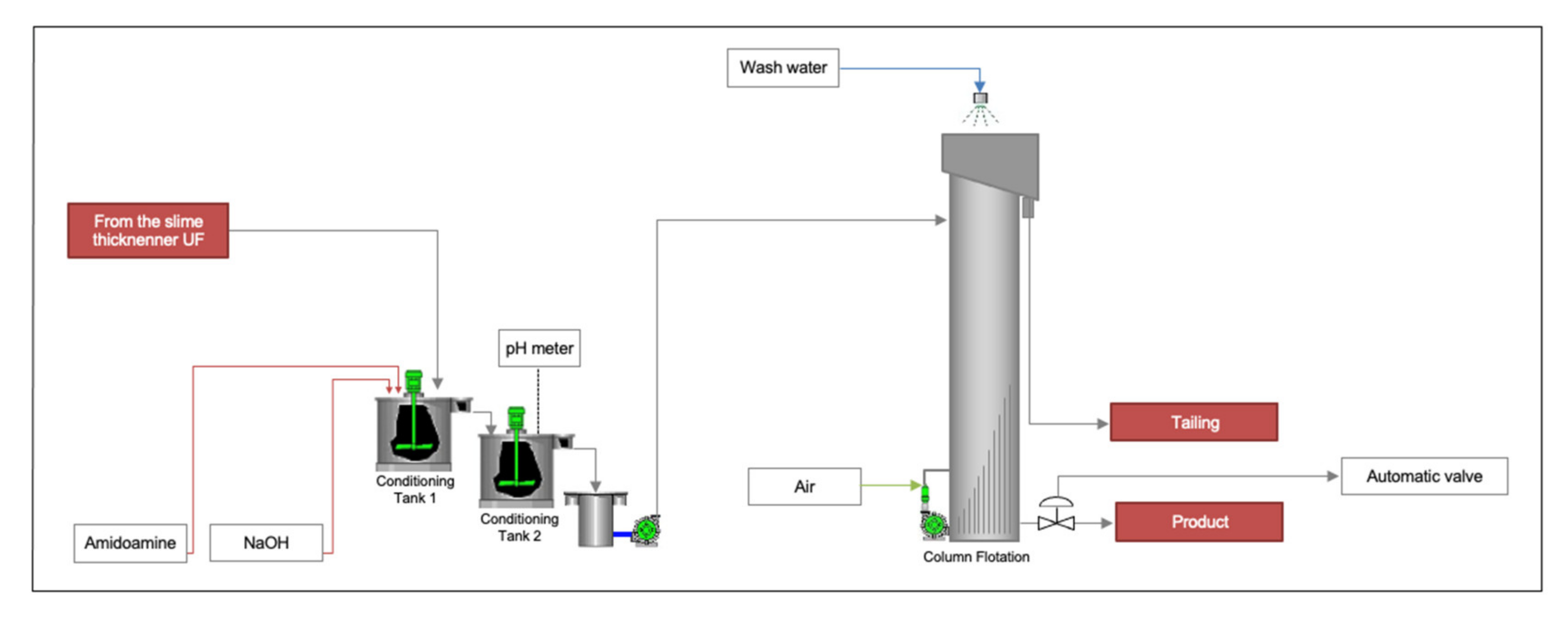
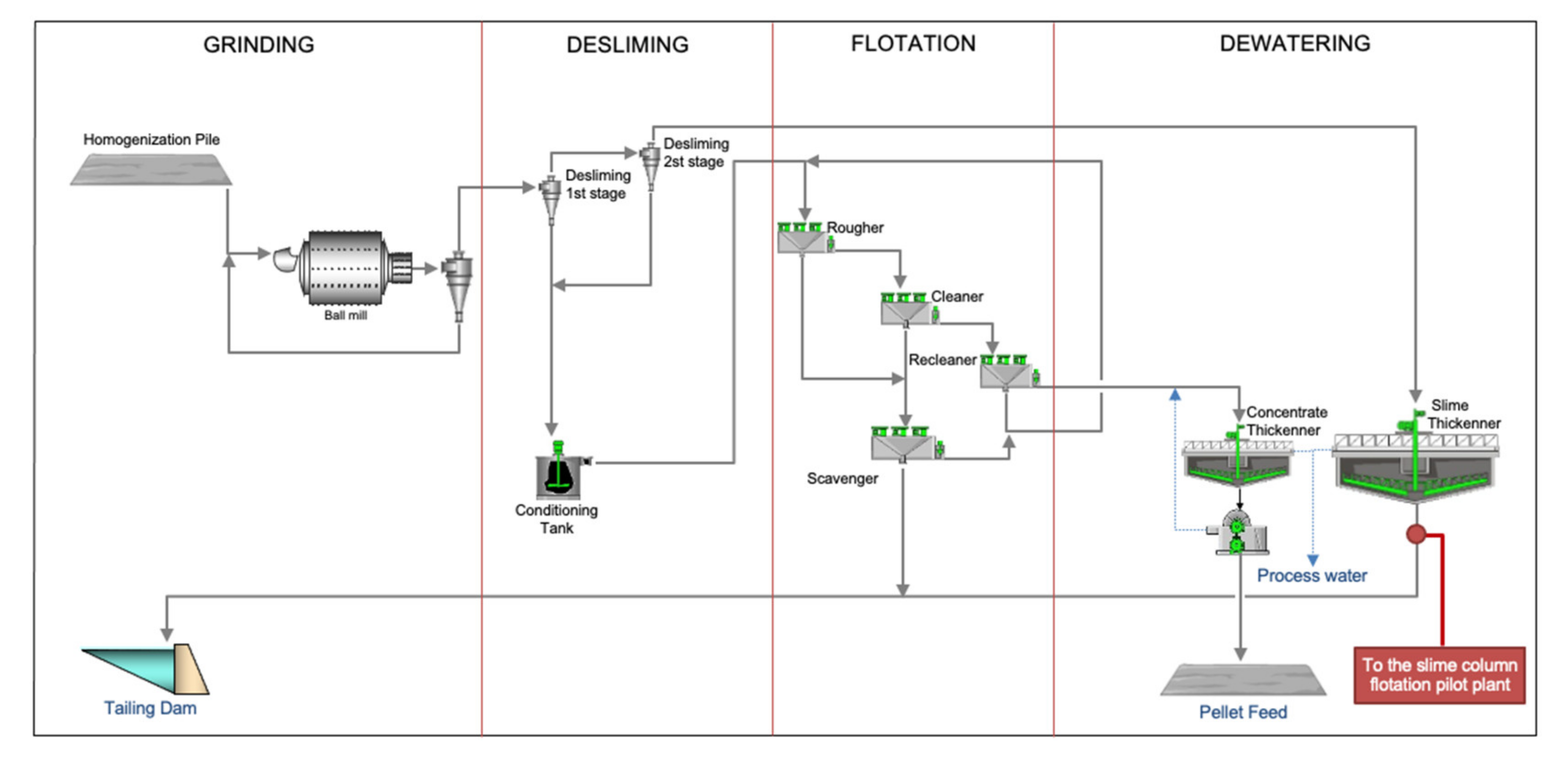
2.1. Industrial Plant
2.2. Pilot Plant
2.3. Reagents
2.4. Characterization
2.5. Operational Parameters of Flotation Column
- Slurry residence time
- Liquid velocity
- Bubble rise velocity
3. Results
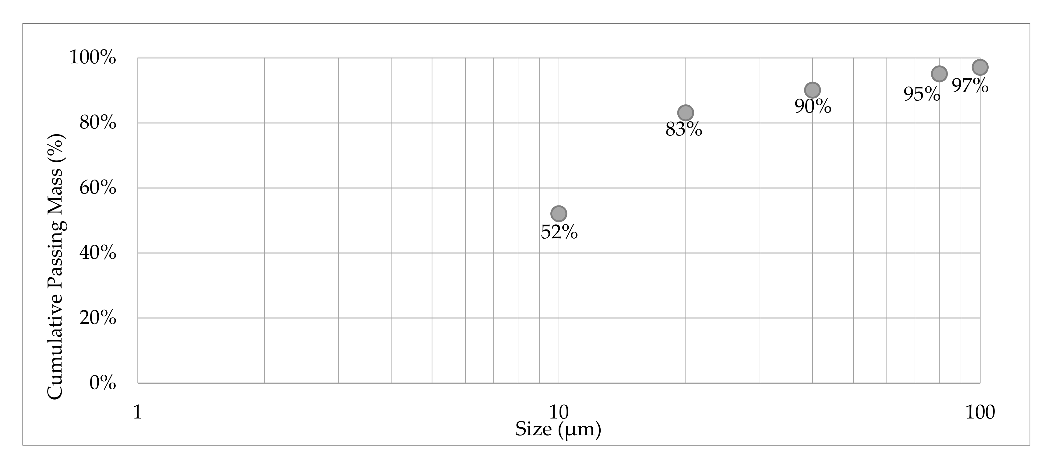
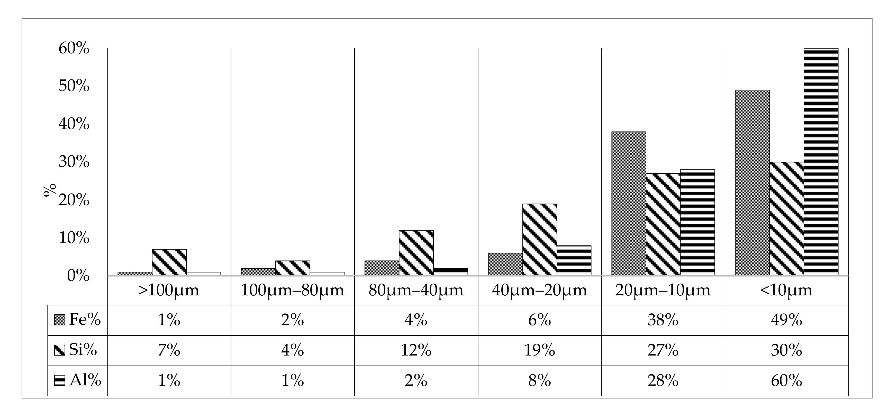
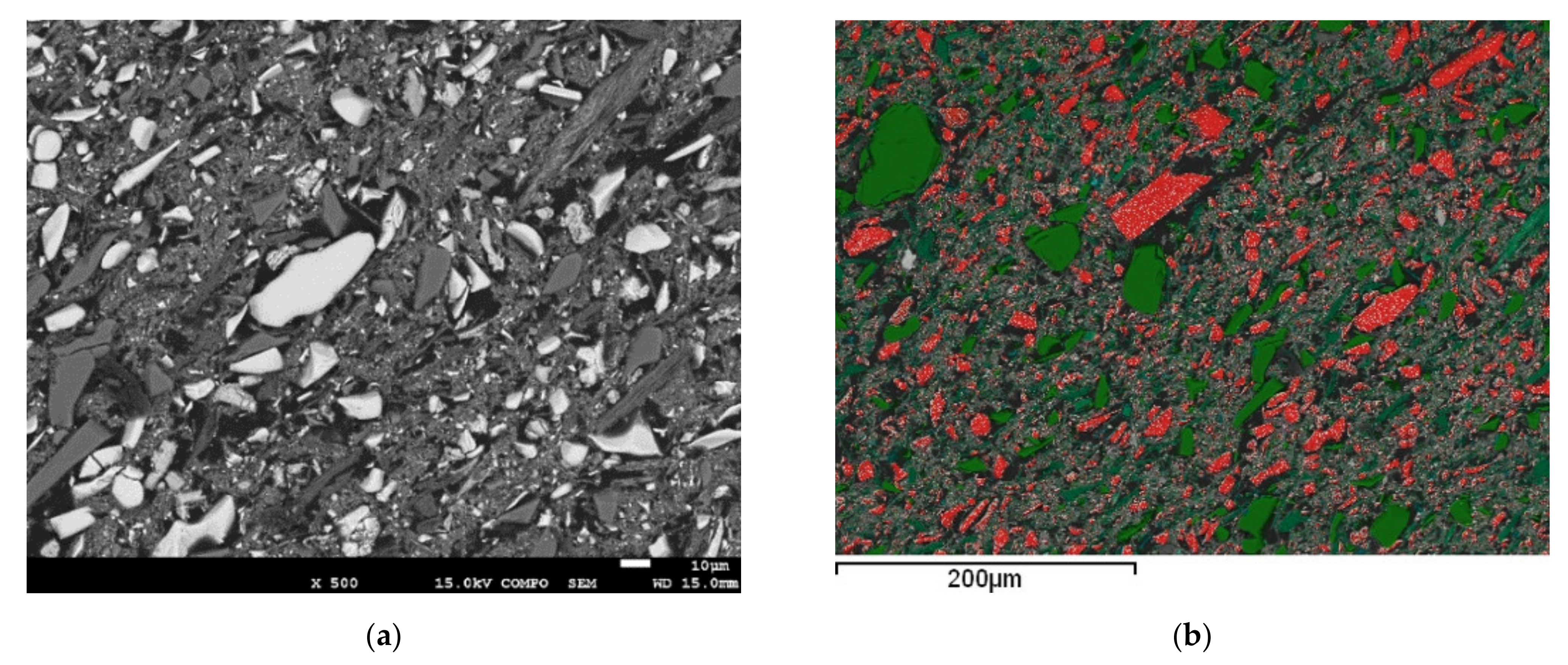
3.1. Sample Characterization
3.2. Pilot Flotation General Conditions
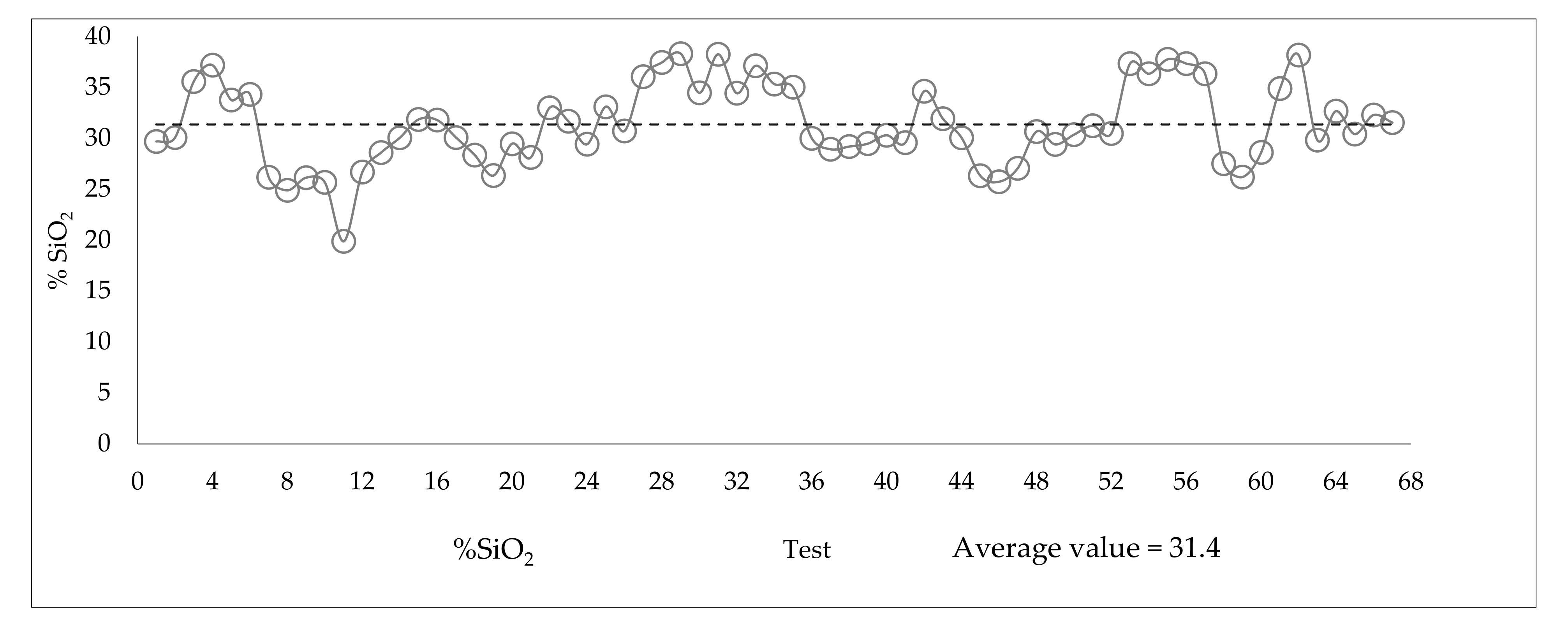
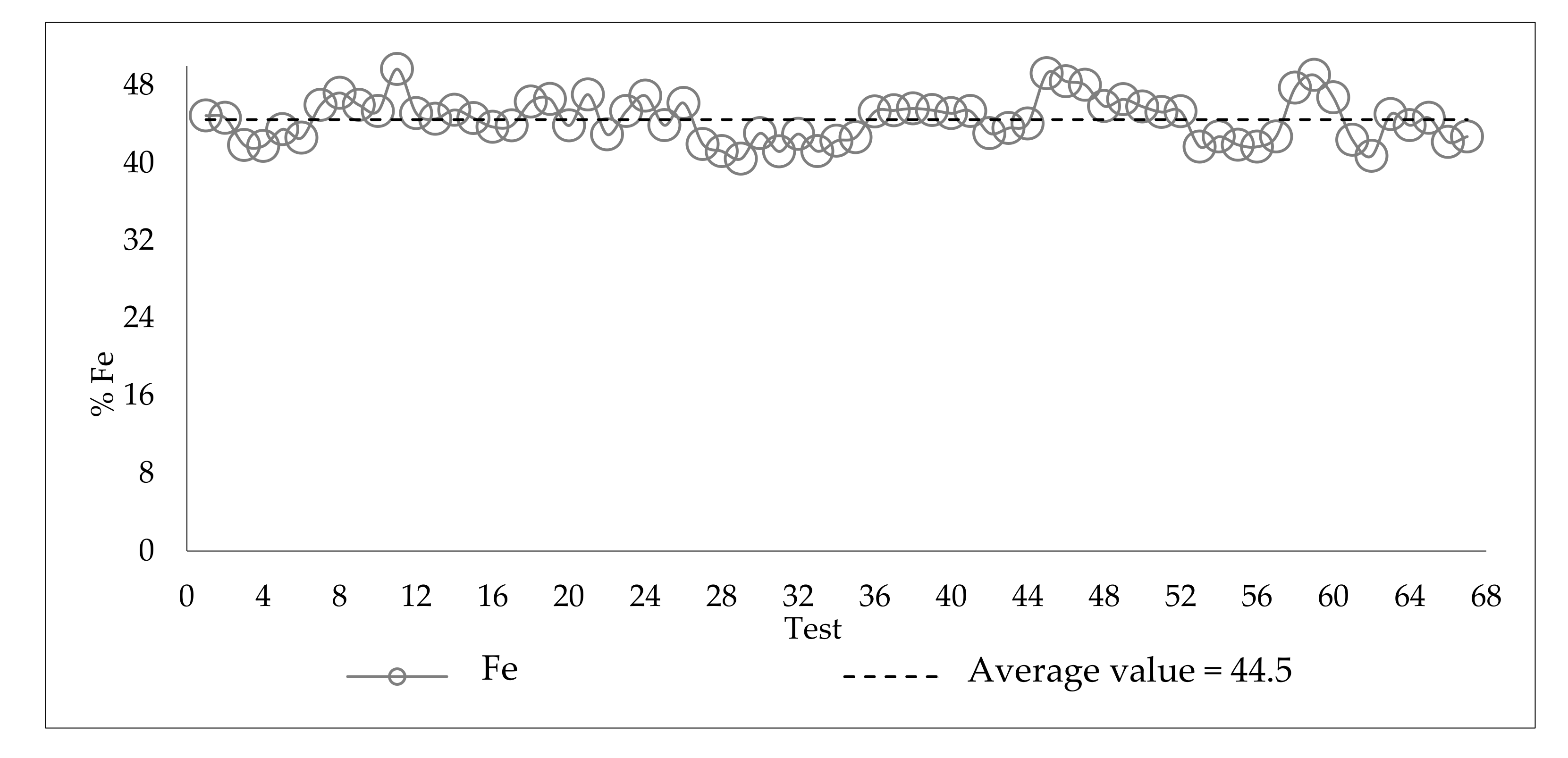
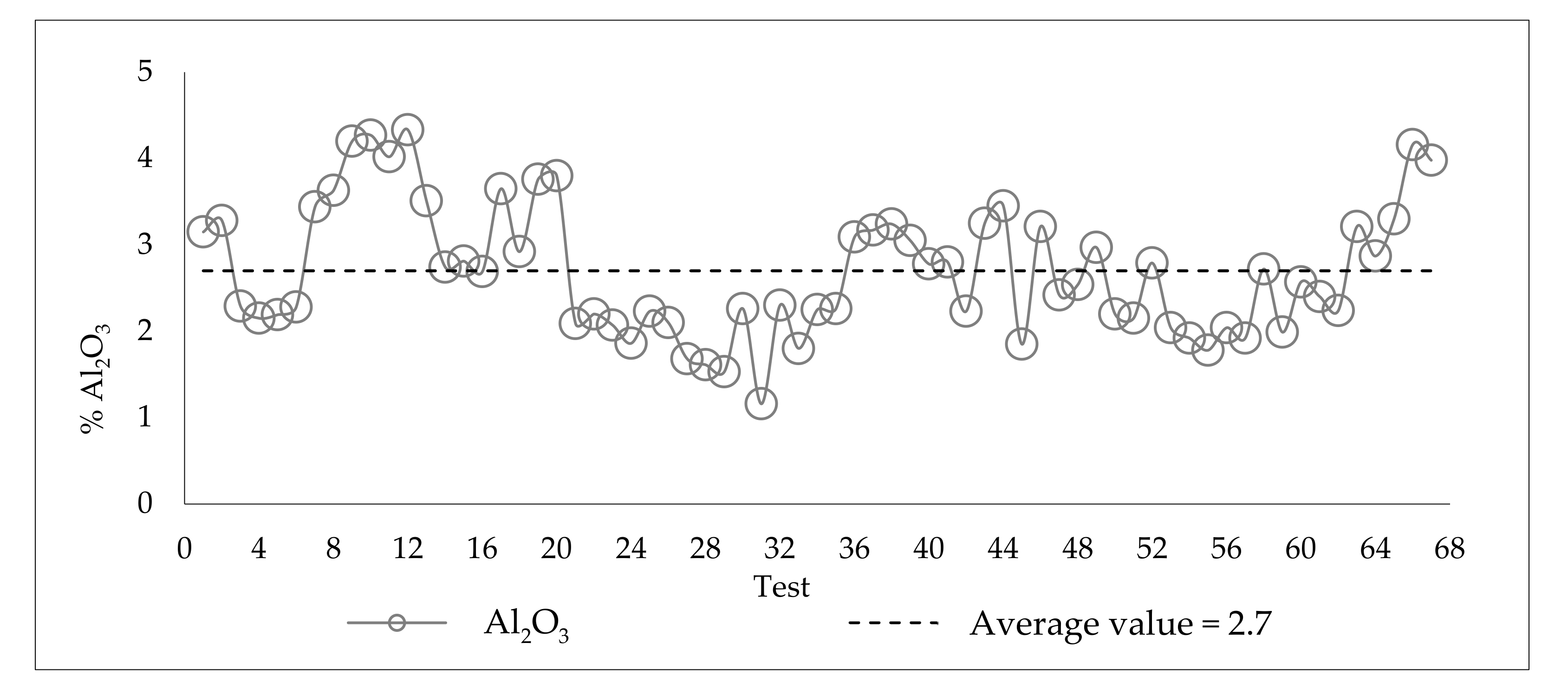
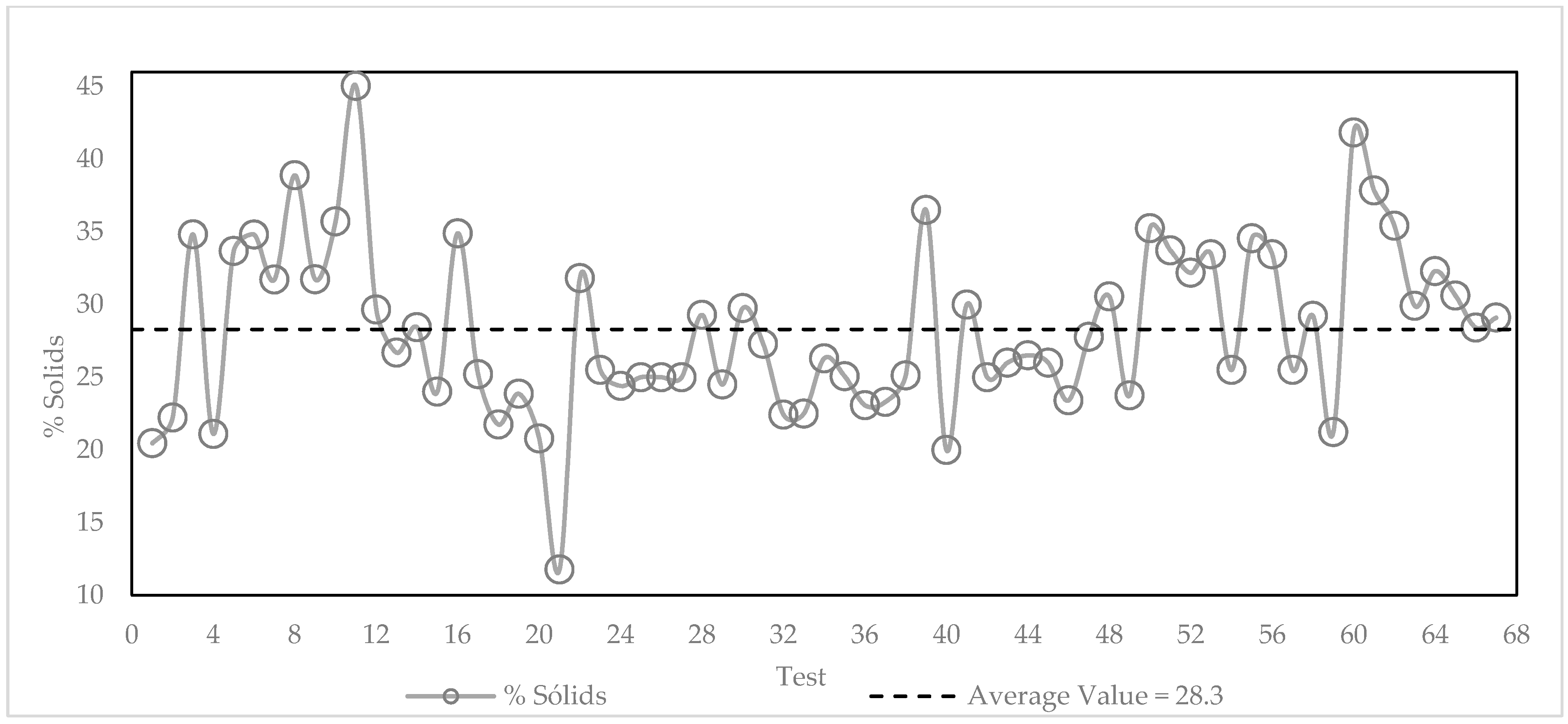
3.3. Variability of the Slimes in the Industrial Plant
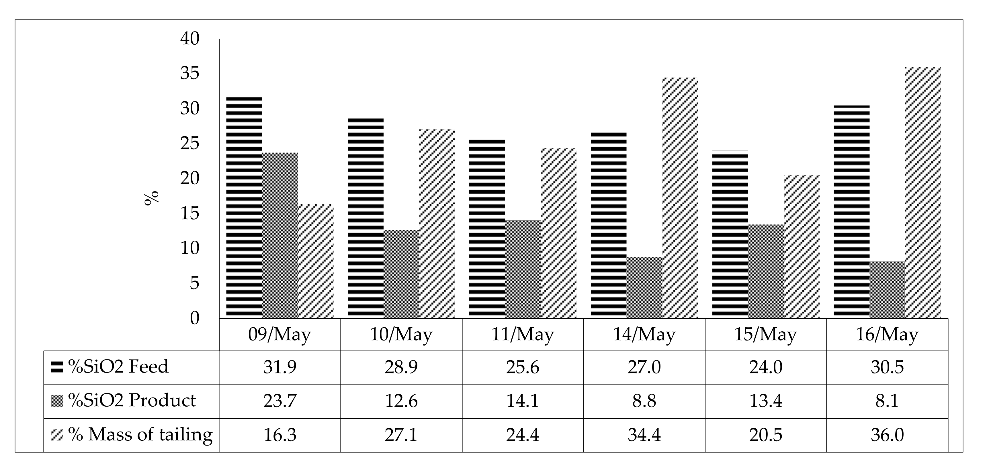
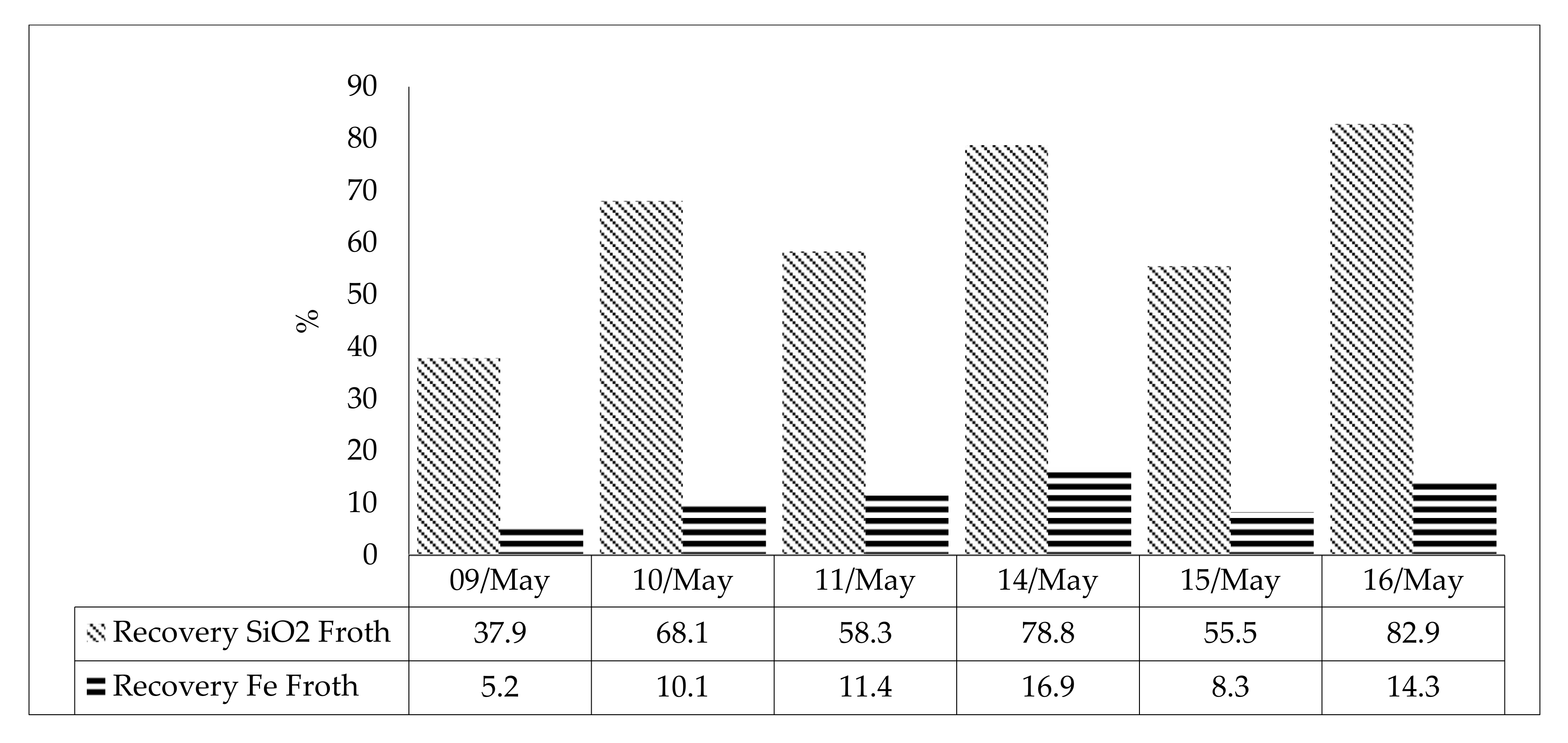
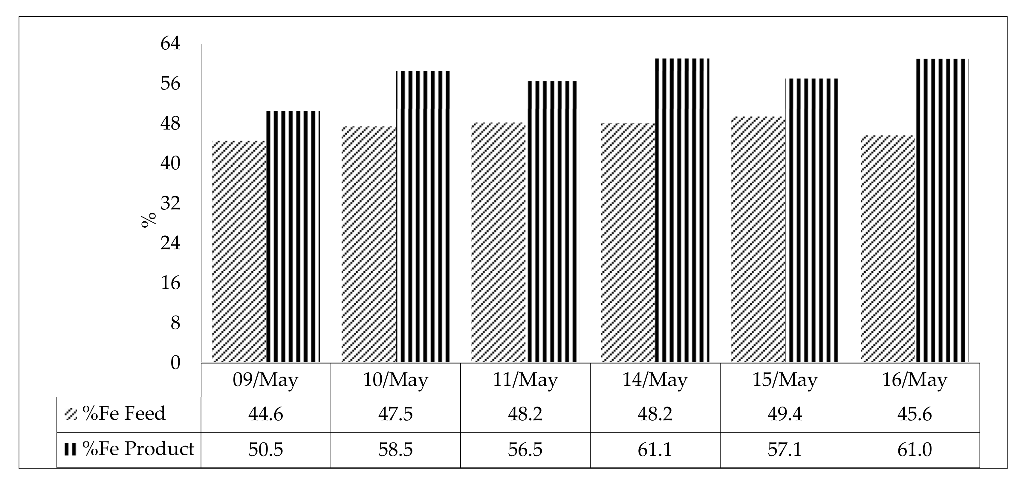
3.4. Initial Pilot Flotation Tests—Summary Results for a 6-Day Test Period
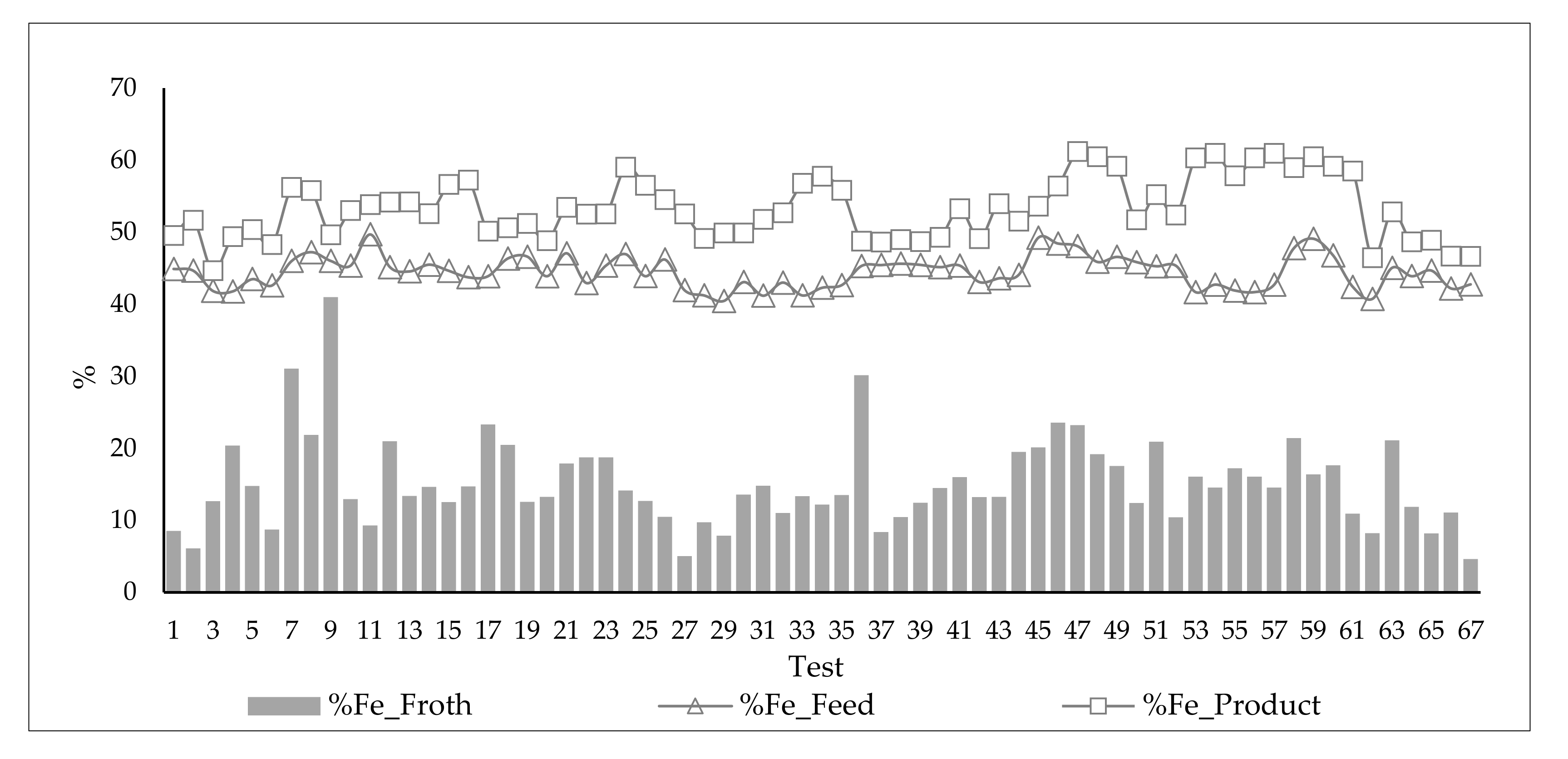
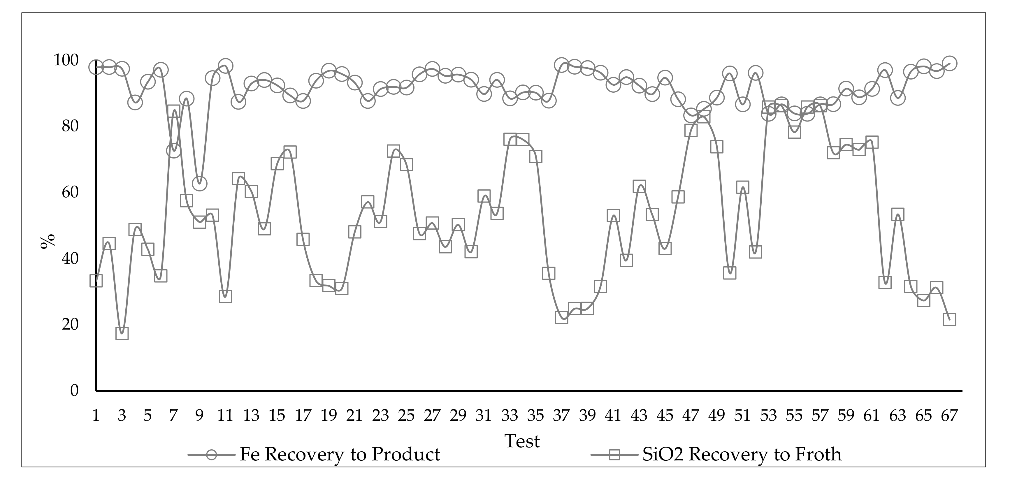
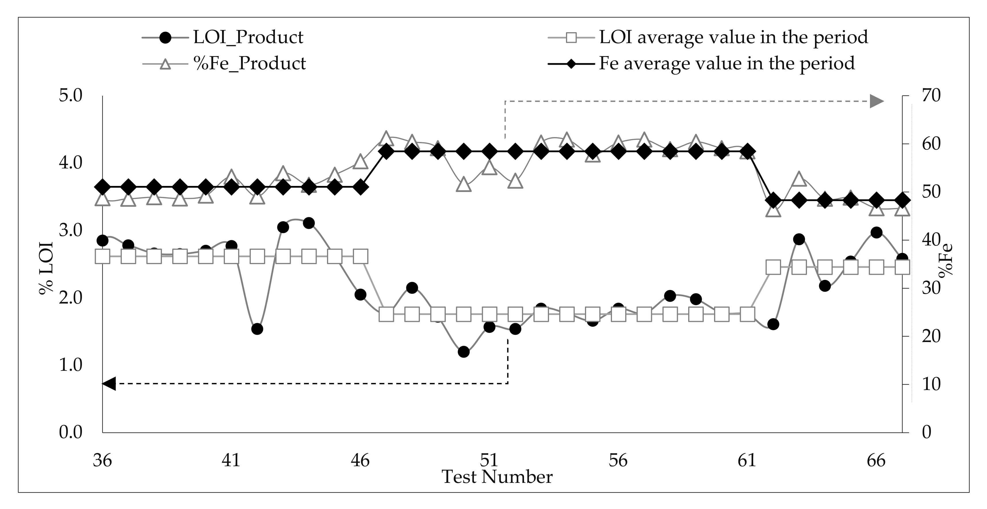
3.5. Analysis of the Influence of Feed Variability and Operational Parameters on Flotation Results during the 67 Pilot Test Campaign
3.5.1. Results
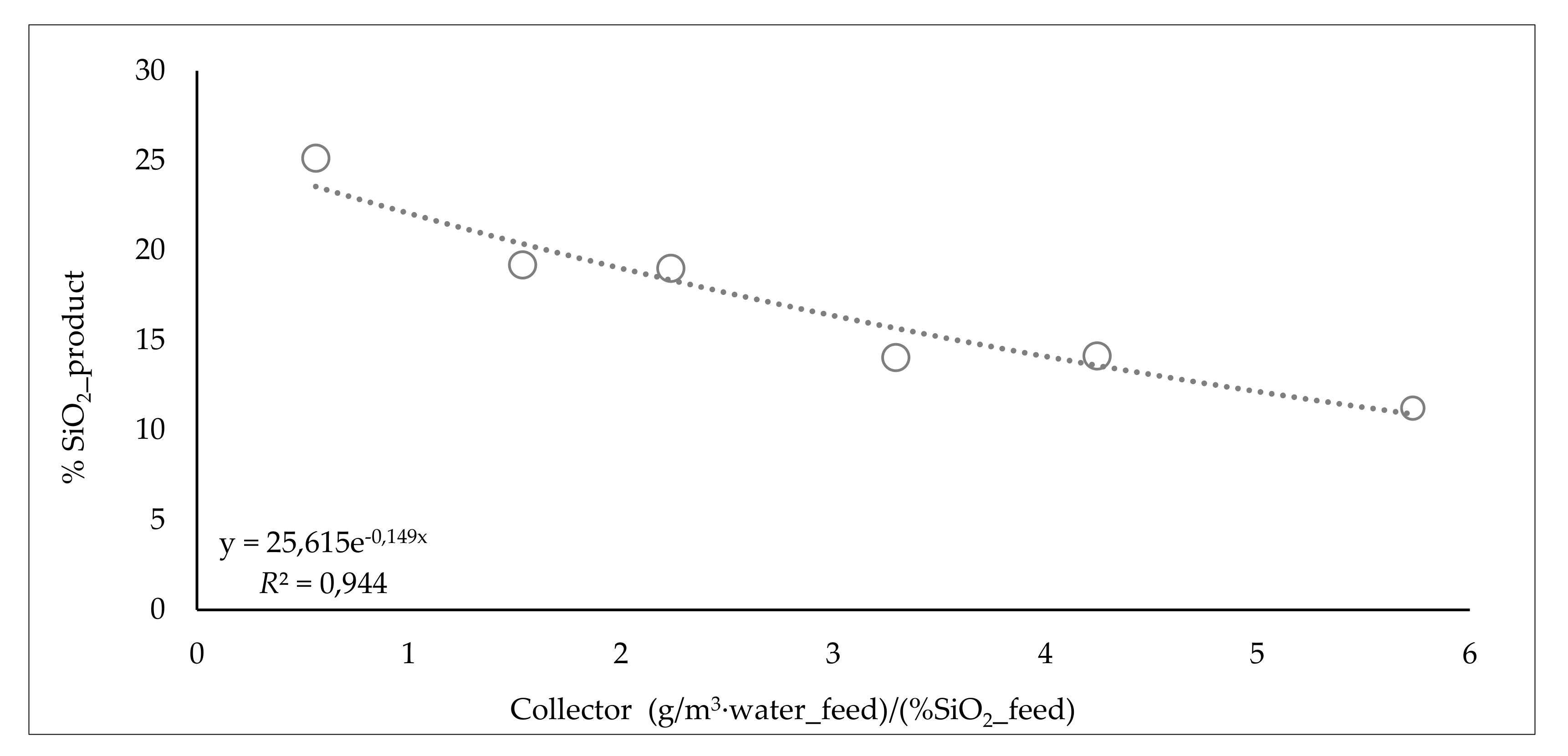
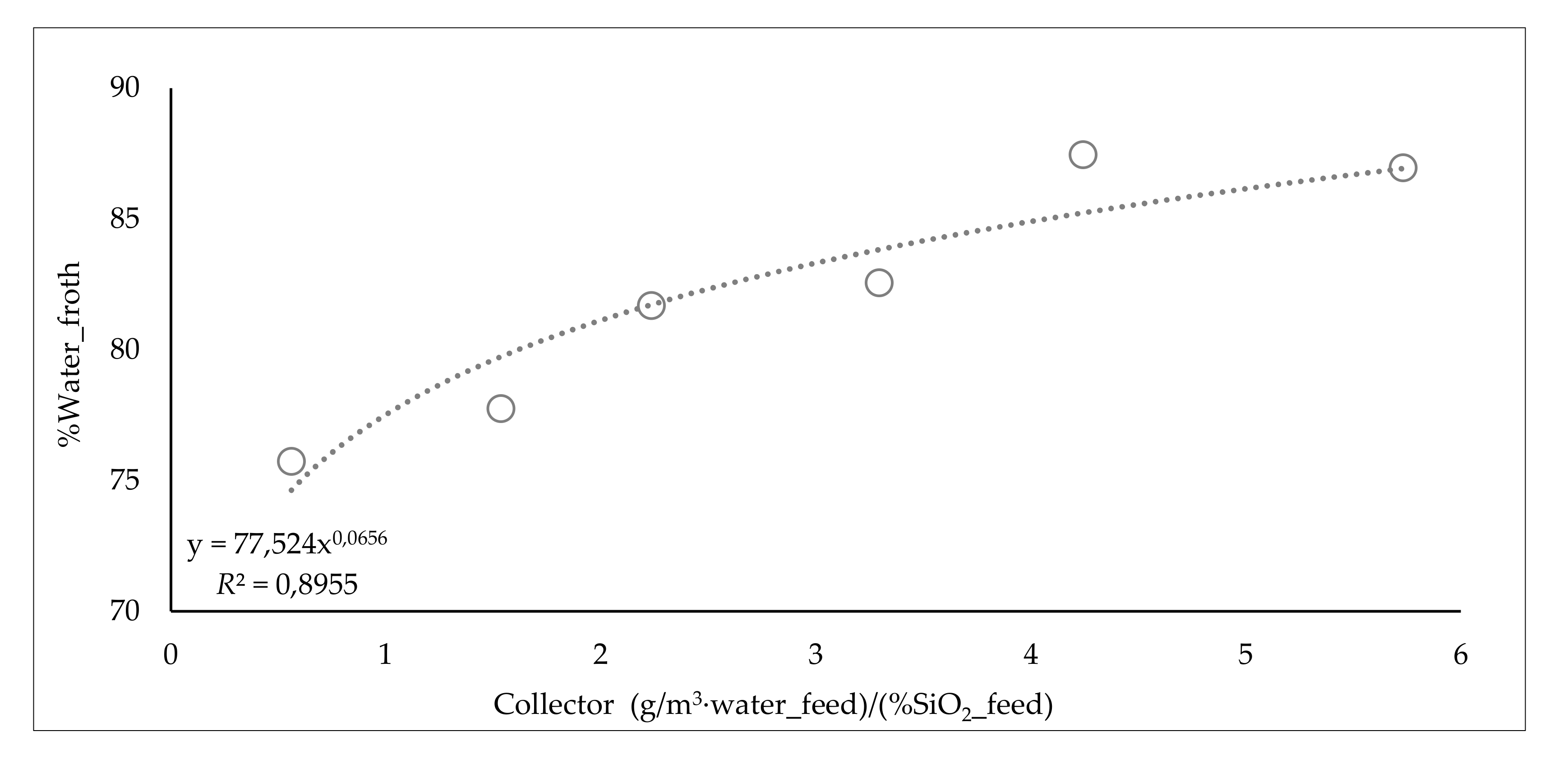
3.5.2. Influence of Collector Dosage
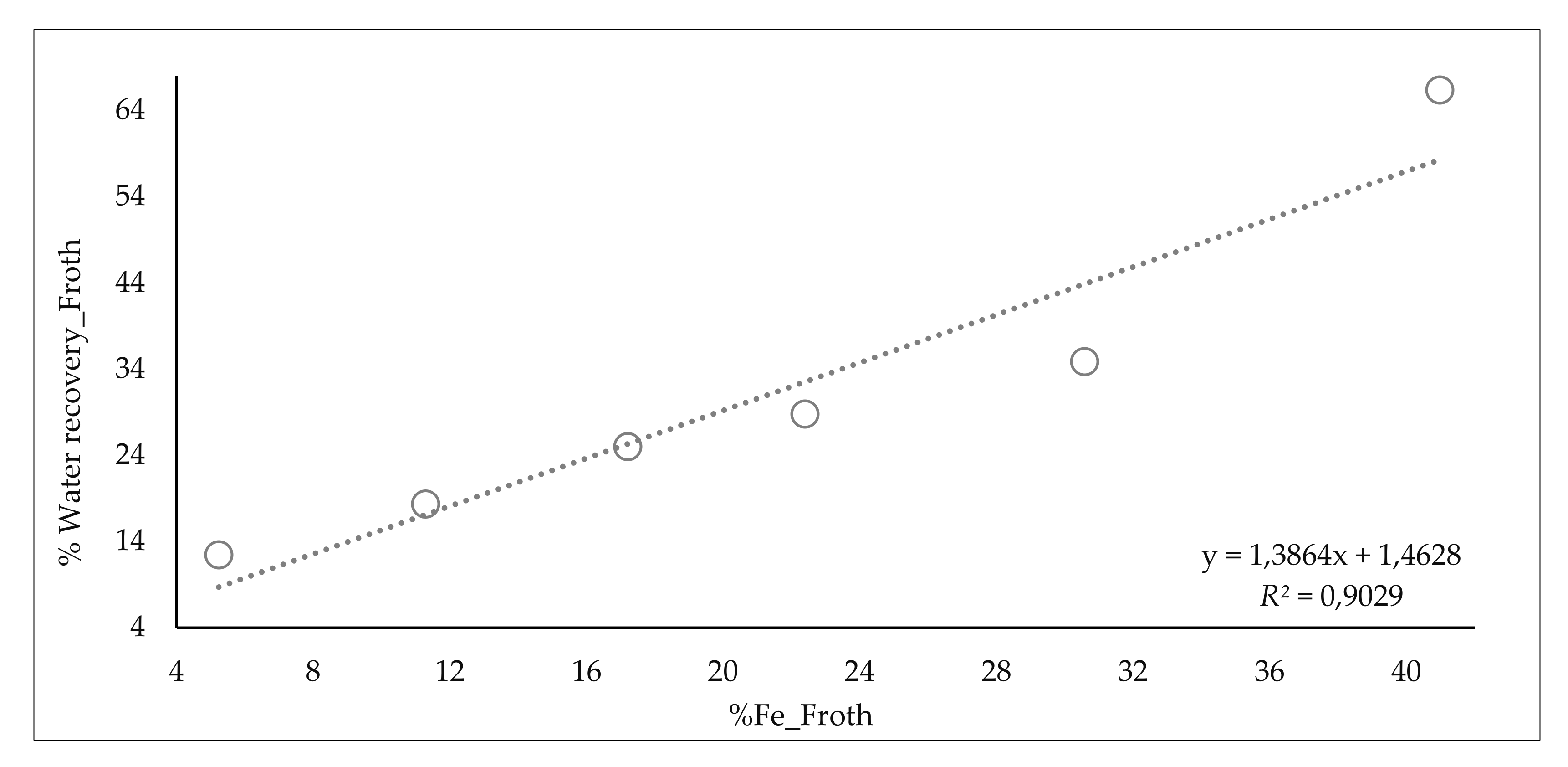
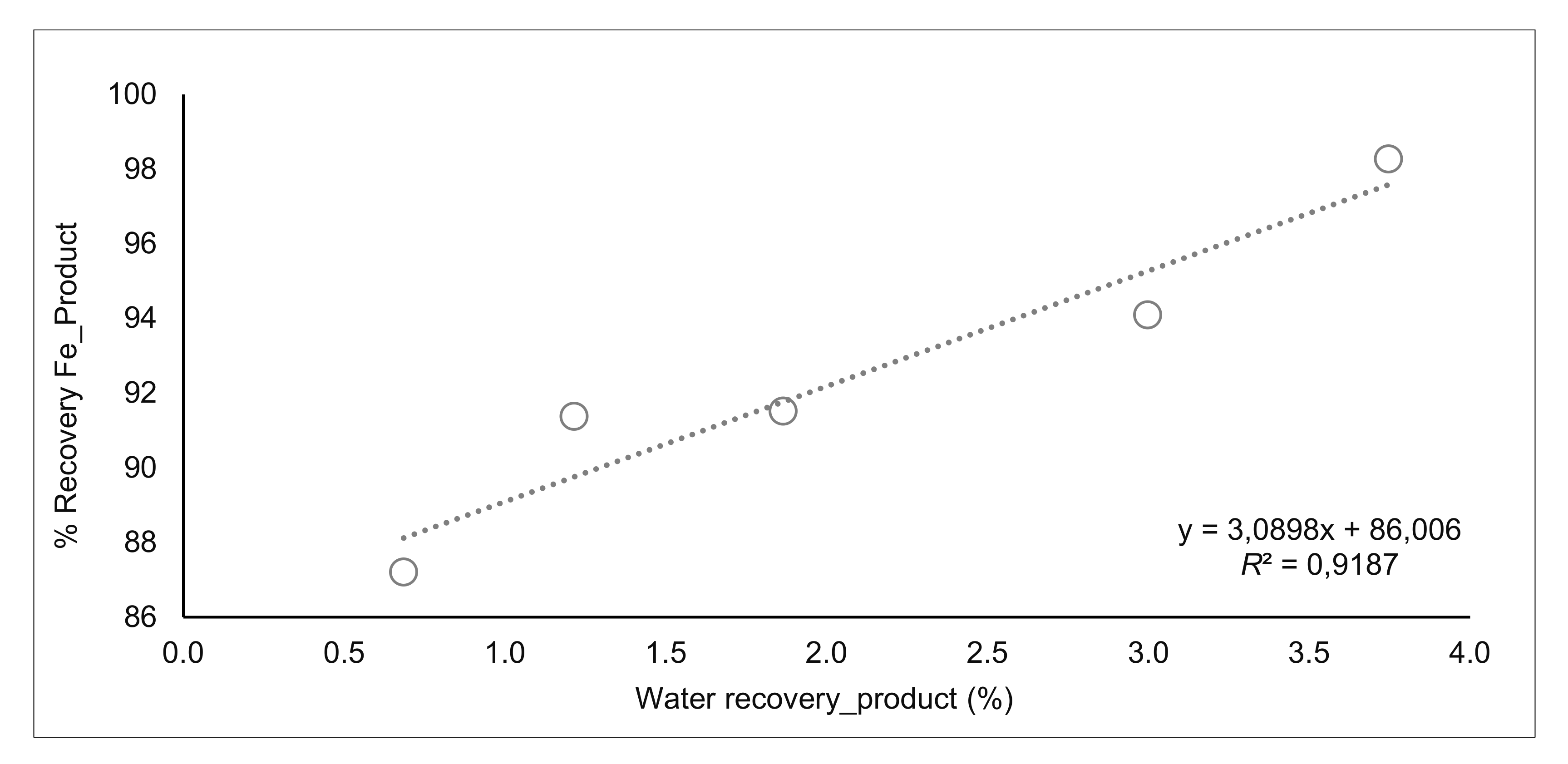
3.5.3. Influence of Water Recovery
3.5.4. Influence of Washing Water
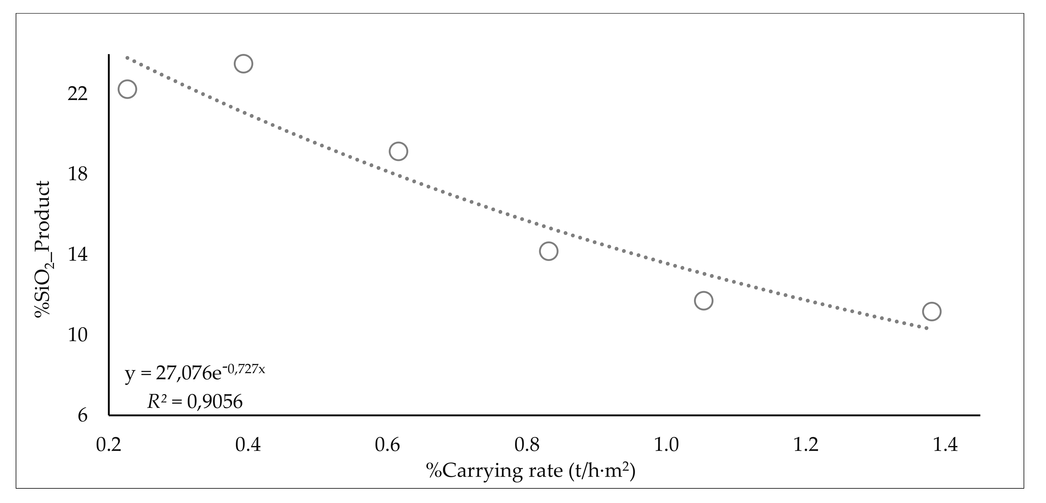
3.5.5. Carrying Rates
3.6. General Discussions
3.6.1. Control System
3.6.2. Product Quality and the Challenge of Slimes Concentration in Brazil
4. Conclusions
Author Contributions
Funding
Data Availability Statement
Acknowledgments
Conflicts of Interest
References
- Clemmer, J.B. Flotation of iron ore. In Proceedings of the 8th Annual Mining Symposium, Duluth, MN, USA, 15 January 1947. [Google Scholar]
- Filippov, L.; Severov, V.; Filippova, I. An overview of the beneficiation of iron ores via reverse cationic flotation. Int. Nat. J. Miner. Process. 2014, 127, 62–69. [Google Scholar] [CrossRef]
- Achaye, I. Effect of Mineral Particle Size on Froth Stability. Ph.D. Thesis, University of Cape Town, Cape Town, South Africa, March 2017. [Google Scholar]
- Mackay, I.; Videla, A.R.; Brito-Parada, P.R. The link between particle size and froth stability - Implications for reprocessing of flotation tailings. J. Clean. Prod. 2020, 242, 118436. [Google Scholar] [CrossRef]
- Norori-McCormac, A.; Brito-Parada, P.R.; Hadler, K.; Cole, K.; Cilliers, J.J. The effect of particle size distribution on froth stability in flotation. Sep. Purif. Technol. 2017. [Google Scholar] [CrossRef]
- Rocha, L.; Cançado, R.Z.L.; Peres, A.E.C. Iron ore slimes flotation. Miner. Eng. 2010, 23, 842–845. [Google Scholar] [CrossRef]
- Haselhuhn, H.J.; Kawatra, K. Effects of Water Chemistry on Hematite Selective Flocculation and Dispersion. Miner. Process. Extr. Metall. Rev. 2015, 36, 305–309. [Google Scholar] [CrossRef]
- Houot, R. Beneficiation of iron ore by flotation—Review of industrial and potential applications. Int. J. Miner. Process. 1983, 10, 183–204. [Google Scholar] [CrossRef]
- Weissenborn, P.K.; Warren, L.J.; Dunn, J.G. Optimisation of selective flocculation of ultrafine iron ore. Int. J. Miner. Process. 1994, 42, 191–213. [Google Scholar] [CrossRef]
- Trahar, W.J. A rational interpretation of the role of particle size in flotation. Int. J. Miner. Process. 1981, 8, 289–327. [Google Scholar] [CrossRef]
- Sivamohan, R. The Problem of Recovering Very Fine Particles in Mineral Processing—A Review. Int. J. Miner. Process. 1990, 28, 247–288. [Google Scholar] [CrossRef]
- Gontijo, C.F.; Fornasiero, D.; Ralston, J. The Limits of Fine and Coarse Particle Flotation. Can. J. Chem. Eng. 2007, 85, 562–785. [Google Scholar]
- Farrokhpay, S.; Filippova, I.; Filippov, L.; Picarra, A.; Rulyov, N. Flotation of fine particles in the presence of combined microbubbles and conventional bubbles. Miner. Eng. 2020, 155. [Google Scholar] [CrossRef]
- Oliveira, H.; Azevedo, A.; Rubio, J. Nanobubbles generation in a high-rate hydrodynamic cavitation tube. Miner. Eng. 2017. [Google Scholar] [CrossRef]
- Fan, M.; Zhao, Y.; Tao, D. Fundamental studies of nanobubble generation and applications in flotation. In Separation Technologies for Minerals Coal and Earth Ressources; SME: Littleton, CO, USA, 2012; pp. 457–469. [Google Scholar]
- Lima, N.P.; Pinto, T.C.S.; Tavares, A.C.; Sweet, J. The entrainment effect on the performance of iron ore reverse flotation. Miner. Eng. 2016. [Google Scholar] [CrossRef]
- Lima, R.M.F.; Abreu, F.P.V.F. Characterization and concentration by selective flocculation/magnetic separation of iron ore slimes from a dam of Quadrilátero Ferrífero—Brazil. J. Mater. Res. Technol. 2020, 9, 2021–2027. [Google Scholar] [CrossRef]
- Ma, X.; Bruckard, W.J.; Holmes, R. Effect of collector, pH and ionic strength on the cationic flotation of kaolinite. Int. J. Miner. Process. 2009, 93, 54–58. [Google Scholar] [CrossRef]
- Xu, L.; Hu, Y.; Faqin, D.; Hao, J.; Wu, H.; Zhen, W.; Ruohua, L. Effects of particle size and chain length on flotation of quaternary ammonium salts onto kaolinite. Min. Pet. 2014. [Google Scholar] [CrossRef] [Green Version]
- Ma, X.; Bruckard, W.J. The effect of pH and ionic strength on starch–kaolinite interactions. Int. J. Miner. Process. 2010, 94, 111–114. [Google Scholar] [CrossRef]
- Nykänen, V.P.S.; Braga, A.S.; Pinto, T.C.S.; Matai, P.H.L.S.; Lima, N.P.; Filho, L.S.L.; Monte, M.B.M. True flotation versus entrainment in reverse cationic flotation for the concentration of iron ore at industrial scale. Miner. Process. Extr. Metall. Rev. 2018, 41. [Google Scholar] [CrossRef]
- Filippov, L.; Filippova, I.; Severov, V. The use of collectors mixture of various molecular structure in the reverse cationic flotation of magnetite ore. Miner. Eng. 2020, 23, 91–98. [Google Scholar] [CrossRef]
- Filippov, L.; Severov, V.; Filippova, I. Mechanism of starch adsorption on Fe-Mg-Al-bearing amphiboles. Int. J. Miner. Process. 2013, 123, 120–128. [Google Scholar] [CrossRef]
- Severov, V.; Filippova, I.; Filippov, L. Floatability of Fe-bearing silicates in the presence of starch: Adsorption and spectroscopic studies. J. Phys. Conf. Ser. 2013, 416, 012017. [Google Scholar] [CrossRef] [Green Version]
- Veloso, C.H.; Filippov, L.O.; Filippova, I.; Ouvrard, S.; Araujo, A.C. Adsorption of polymers onto iron oxides: Equilibrium isotherms. J. Mater. Res. Technol. 2019, 9, 779–788. [Google Scholar] [CrossRef]
- Araujo, V.A.; Lima, N.P.; Azevedo, A.; Rubio, J. Column reverse rougher flotation of iron bearing fine tailings assisted by HIC and a new cationic collector. Miner. Eng. 2020, 156. [Google Scholar] [CrossRef]
- Matiolo, E.; Couto, H.J.B.; Lima, N.; Klaydison, S. Improving recovery of iron using column flotation of iron ore slimes. Miner. Eng. 2020, 158. [Google Scholar] [CrossRef]
- Klaydison, S.; Filippov, L.; Piçarra, A.; Filippova, I.; Lima, N.; Skliar, A.; Filho, L. New perspectives in iron ore flotation: Use of collector reagents without depressants in reverse cationic flotation of quartz. Miner. Eng. 2021, 170. [Google Scholar] [CrossRef]
- Ma, X.; Marques, M.; Gontijo, C. Comparative studies of reverse cationic/anionic flotation of Vale iron ore. Int. J. Miner. Process. 2011, 100, 179–183. [Google Scholar] [CrossRef]
- Fornasiero, D.; Filippov, L. Innovations in the flotation of fine and coarse particles. J. Phys. Conf. Ser. 2017, 879. [Google Scholar] [CrossRef] [Green Version]
- Clout, J.M.F.; Manuel, J.R. Minealogica, chemical and physical characteristics of iron ore. In Iron Ore Mineralogy, Processing and Environmental Sustaibability; Elsevier: Amsterdam, The Netherlands, 2015. [Google Scholar]
- Bruckard, W.J.; Smith, L.K.; Heyes, G.W. Developments in the physiochemical separation of iron ore. In Iron Ore; Woodhead Publishing: Sawston, UK, 2015; pp. 339–356. [Google Scholar] [CrossRef]
- Trahar, W.J.; Warren, L.J. The flotability of very fine particles—A review. Int. J. Miner. Process. 1976, 3, 103–131. [Google Scholar] [CrossRef]
- Araujo, A.C.; Amarante, S.C.; Souza, C.C.; Silva, R.R.R. Ore mineralogy and its relevance for selection of concentration methods in processing of Brazilian iron ores. Miner. Process. Extr. Metall. 2003, 112, 54–64. [Google Scholar] [CrossRef]
- Lima, N.P.; Valadão, G.E.S.; Peres, A.E.C. Effect of particles size range on iron ore flotation. Rem: Rev. Esc. De Minas 2013, 66. [Google Scholar] [CrossRef] [Green Version]
- Schulze, H.J.; Radoev, B.; Geidel Th Stechemesser, H.; Topfer, E. Investigations of the Collision Process between Particles and Gas Bubbles in Flotation—A Theoretical Analysis. Int. J. Miner. Process. 1989, 27, 263–278. [Google Scholar] [CrossRef]
- Chipfunhu, D.; Zanin, M.; Grano, S. Flotation behaviour of fine particles with respect to contact angle. Chem. Eng. Res. Des. 2012, 90, 26–32. [Google Scholar] [CrossRef]
- Scheludko, A.; Toshev, B.V.; Bojadjiev, D.T. Attachment of Particles to a Liquid Surface (Capillary Theory of Flotation). J. Chem. Soc. Faraday Trans. 1: Phys. Chem. Condens. Phases 1976, 72. [Google Scholar] [CrossRef]
- Souza, H.S.; Braga, A.S.; Oliveira, A.H.; Filho, L.S.L. Concentration of manganese tailings via reverse flotation in an acid médium. Rem: Rev. Esc. De Minas 2016, 69, 85–90. [Google Scholar] [CrossRef]
- Kracht, W.; Orozco, Y.; Acuña, C. Effect of surfactant type on the entrainment factor and selectivity of flotation at laboratory scale. Miner. Eng. 2016, 92, 216–220. [Google Scholar] [CrossRef]
- Melo, F.; Laskowski, J.S. Effect of frothers and solid particles on the rate of water transfer to froth. Int. J. Miner. Process. 2007, 84, 33–40. [Google Scholar] [CrossRef]
- Moyo, P.; Gomes, C.O.; Finch, J.A. Characterizing frothers using water carrying rate. Can. Metall. Q. 2007, 46, 215–220. [Google Scholar] [CrossRef]
- Matos, V.E.; Nogueira, S.C.S.; Silva, G.; Kowalczuk, P.B. Differences in Etheramines Froth Properties and the Effects on Iron Ore Flotation. Part II: Three-Phase Systems. Miner. Process. Extr. Metall. Rev. 2021. [Google Scholar] [CrossRef]
- Somasundaran, P. Fine particles treatment. In Workshop on Research Needs in Mineral Processing; Columbia University: New York, NY, USA, 1976. [Google Scholar]
- Kursun, H. Effect of Fine Particles’ Entrainment on Conventional and Column Flotation. Part. Sci. Technol. 2014, 32, 251–256. [Google Scholar] [CrossRef]
- Tan, J.; Wang, J.; Nguyen, A.V.; Xie, G. Regimes of drainage instability caused by wash water. Miner. Eng. 2020, 148, 160202. [Google Scholar] [CrossRef]
- Soto, H.S. Column flotation with negative bias. In Proceedings of the International Symposium on Processing of Complex Ores, Halifax, UK, 20–24 August 1989; pp. 379–385. [Google Scholar]
- Flint, I.M.; Wyslouzil, H.E.; Andrade, V.L.L.; Murdock, D.J. Column flotation of iron ore. Miner. Eng. 1992, 10–12, 1185–1194. [Google Scholar] [CrossRef]
- Kursun, H. Determination of Carrying Capacity Using Talc in Column Flotation. Arab. J. Sci. Eng. 2011, 36, 703. [Google Scholar] [CrossRef]
- Espinosa-Gomez, R.; Finch, J.A.; Yianatos, J.B.; Dobby, G.S. Technical Note: Flotation Column Carrying Capacity: Particle SIZE and Density Effects. Miner. Eng. 1988, 1 N1, 77–79. [Google Scholar] [CrossRef]
- Yianatos, J.B.; Contreras, F.A. On the Carrying Capacity Limitation in Large Flotation Cells. Can. Metall. Q. 2010, 49, 345–352. [Google Scholar] [CrossRef]
- Bergh, L.G.; Yianatos, J.B. Flotation column automation: State of the art. Control Eng. Pract. 2003, 11, 67–72. [Google Scholar] [CrossRef]
- Beuria, P.C.; Biswal, S.K.; Mishra, B.K.; Roy, G.G. Study on kinetics of thermal decomposition of low LOI goethetic hematite iron ore. Int. J. Min. Sci. Technol. 2017. [Google Scholar] [CrossRef]
- Svoboda, J.; Fujita, T. Recent developments in magnetic methods of material separation. Miner. Eng. 2003, 16, 785–792. [Google Scholar] [CrossRef]


| Name | Type of Reagent/Role | Comments: |
|---|---|---|
| Flotinor 5530 | Collector | Amidoamine |
| Sodium hydroxide | pH Modifier | - |
| ID | Fe | SiO2 | Al2O3 | P | Loss on ignition (LOI) |
|---|---|---|---|---|---|
| Slimes Flotation Feed | 44.31 | 31.09 | 2.85 | 0.079 | 2.15 |
| Size Class (μm) | Minerals Identified |
|---|---|
| >106 | Hematite + Goethite + Quartz + Kaolinite + Muscovite |
| 106–80 | Hematite + Quartz + Kaolinite |
| 80–40 | Hematite + Goethite + Quartz + Kaolinite + Muscovite |
| 40–20 | Hematite + Goethite + Quartz + Kaolinite + Muscovite, Chlorite |
| 10–20 | Hematite + Goethite + Quartz + Kaolinite + Muscovite, Chlorite |
| 10–0 | Hematite + Goethite + Quartz + Kaolinite + Muscovite |
| ID | Measured Value |
|---|---|
| Superficial gas velocity (Jg) | 1.94 cm·s−1 |
| Sauter diameter (d3.2) | 0.92 mm |
| Test | ID | Mass (kg/h) | % Solids | Flowrate (l/h) | Water (l/h) | Grade (%) | |||||
|---|---|---|---|---|---|---|---|---|---|---|---|
| Fe | SiO2 | Al2O3 | P | Mn | LOI | ||||||
| 09/may | Feed | 660 | 32.0 | 1582 | 1403 | 44.6 | 31.9 | 2.4 | 0.08 | 0.03 | 1.8 |
| Product | 552 | 14.2 | 3490 | 3349 | 50.5 | 23.7 | 2.1 | 0.10 | 0.04 | 1.8 | |
| Tailings | 108 | 15.4 | 632 | 593 | 14.3 | 74.1 | 3.8 | 0.02 | 0.01 | 1.6 | |
| Washing water (l/h) | 2539 | Recovery Fe Product | 94.8 | Recovery SiO2 Froth | 37.9 | ||||||
| Test | ID | Mass (kg/h) | % Solids | Flowrate (l/h) | Water (l/h) | Grade (%) | |||||
| Fe | SiO2 | Al2O3 | P | Mn | LOI | ||||||
| 10/may | Feed | 640 | 31.2 | 1580 | 1412 | 47.5 | 28.9 | 1.7 | 0.06 | 0.01 | 1.4 |
| Product | 467 | 13.3 | 3141 | 3034 | 58.5 | 12.6 | 1.8 | 0.08 | 0.02 | 1.7 | |
| Tailings | 174 | 26.8 | 535 | 475 | 17.7 | 72.4 | 1.5 | 0.01 | 0.01 | 0.7 | |
| Washing water (l/h) | 2097 | Recovery Fe Product | 89.9 | Recovery SiO2 Froth | 68.1 | ||||||
| Test | ID | Mass (kg/h) | % Solids | Flowrate (l/h) | Water (l/h) | Grade (%) | |||||
| Fe | SiO2 | Al2O3 | P | Mn | LOI | ||||||
| 11/may | Feed | 505 | 26.1 | 1565 | 1433 | 48.2 | 25.6 | 3.2 | 0.07 | 0.02 | 2.0 |
| Product | 382 | 21.5 | 1485 | 1394 | 56.5 | 14.1 | 2.8 | 0.08 | 0.03 | 2.0 | |
| Tailings | 123 | 25.0 | 411 | 370 | 22.6 | 61.2 | 4.4 | 0.03 | 0.01 | 2.1 | |
| Washing water (l/h) | 331 | Recovery Fe Product | 88.6 | Recovery SiO2 Froth | 58.3 | ||||||
| Test | ID | Mass (kg/h) | % Solids | Flowrate (l/h) | Water (l/h) | Grade (%) | |||||
| Fe | SiO2 | Al2O3 | P | Mn | LOI | ||||||
| 14/may | Feed | 430 | 23.4 | 1519 | 1407 | 48.2 | 27.0 | 2.4 | 0.06 | 0.04 | 1.5 |
| Product | 282 | 16.1 | 1528 | 1465 | 61.1 | 8.8 | 2.0 | 0.08 | 0.05 | 1.7 | |
| Tailings | 148 | 19.5 | 661 | 611 | 23.7 | 61.8 | 3.2 | 0.03 | 0.02 | 1.1 | |
| Washing water (l/h) | 669 | Recovery Fe Product | 83.1 | Recovery SiO2 Froth | 78.8 | ||||||
| Test | ID | Mass (kg/h) | % Solids | Flowrate (l/h) | Water (l/h) | Grade (%) | |||||
| Fe | SiO2 | Al2O3 | P | Mn | LOI | ||||||
| 15/may | Feed | 507 | 27.8 | 1449 | 1319 | 49.4 | 24.0 | 3.2 | 0.06 | 0.01 | 2.0 |
| Product | 403 | 16.6 | 2125 | 2030 | 57.1 | 13.4 | 2.8 | 0.07 | 0.01 | 2.0 | |
| Tailings | 104 | 15.5 | 605 | 569 | 19.9 | 64.9 | 4.7 | 0.02 | 0.01 | 1.9 | |
| Washing water (l/h) | 1280 | Recovery Fe Product | 91.7 | Recovery SiO2 Froth | 55.5 | ||||||
| Test | ID | Mass (kg/h) | % Solids | Flowrate (l/h) | Water (l/h) | Grade (%) | |||||
| Fe | SiO2 | Al2O3 | P | Mn | LOI | ||||||
| 16/may | Feed | 600 | 30.6 | 1525 | 1364 | 45.6 | 30.5 | 2.5 | 0.05 | 0.01 | 1.6 |
| Product | 384 | 14.1 | 2422 | 2336 | 61.0 | 8.1 | 2.5 | 0.07 | 0.01 | 1.9 | |
| Tailings | 216 | 23.8 | 766 | 691 | 18.2 | 70.2 | 2.6 | 0.01 | 0.01 | 1.1 | |
| Washing water (l/h) | 1663 | Recovery Fe Product | 85.7 | Recovery SiO2 Froth | 82.9 | ||||||
| ID | %Fe Feed | %Fe Product | %Fe Tailing | Mass Recovery | Fe Recovery Product | SiO2 Recovery Froth | |
|---|---|---|---|---|---|---|---|
| Average Value | 44.5 | 53.3 | 15.2 | 76.9 | 91.5 | 53.1 | |
| 90th percentile | 47.1 | 59.6 | 21.6 | 89.1 | 97.7 | 78.5 | |
| Median | 44.6 | 52.6 | 14.1 | 76.8 | 92.4 | 51.2 | |
| 10th percentile | 41.7 | 48.6 | 8.4 | 62.8 | 86.1 | 30.0 | |
| ID | JL (cm·s−1) | JSL (cm·s−1) | JW (cm·s−1) | ||||
| Feed | Product | Tail | Feed | Product | Tail | ||
| Average Value | 0.18 | 0.25 | 0.07 | 0.20 | 0.26 | 0.08 | 0.14 |
| 90th percentile | 0.20 | 0.29 | 0.13 | 0.22 | 0.31 | 0.14 | 0.19 |
| Median | 0.19 | 0.23 | 0.06 | 0.21 | 0.24 | 0.07 | 0.11 |
| 10th percentile | 0.18 | 0.18 | 0.03 | 0.21 | 0.19 | 0.03 | 0.07 |
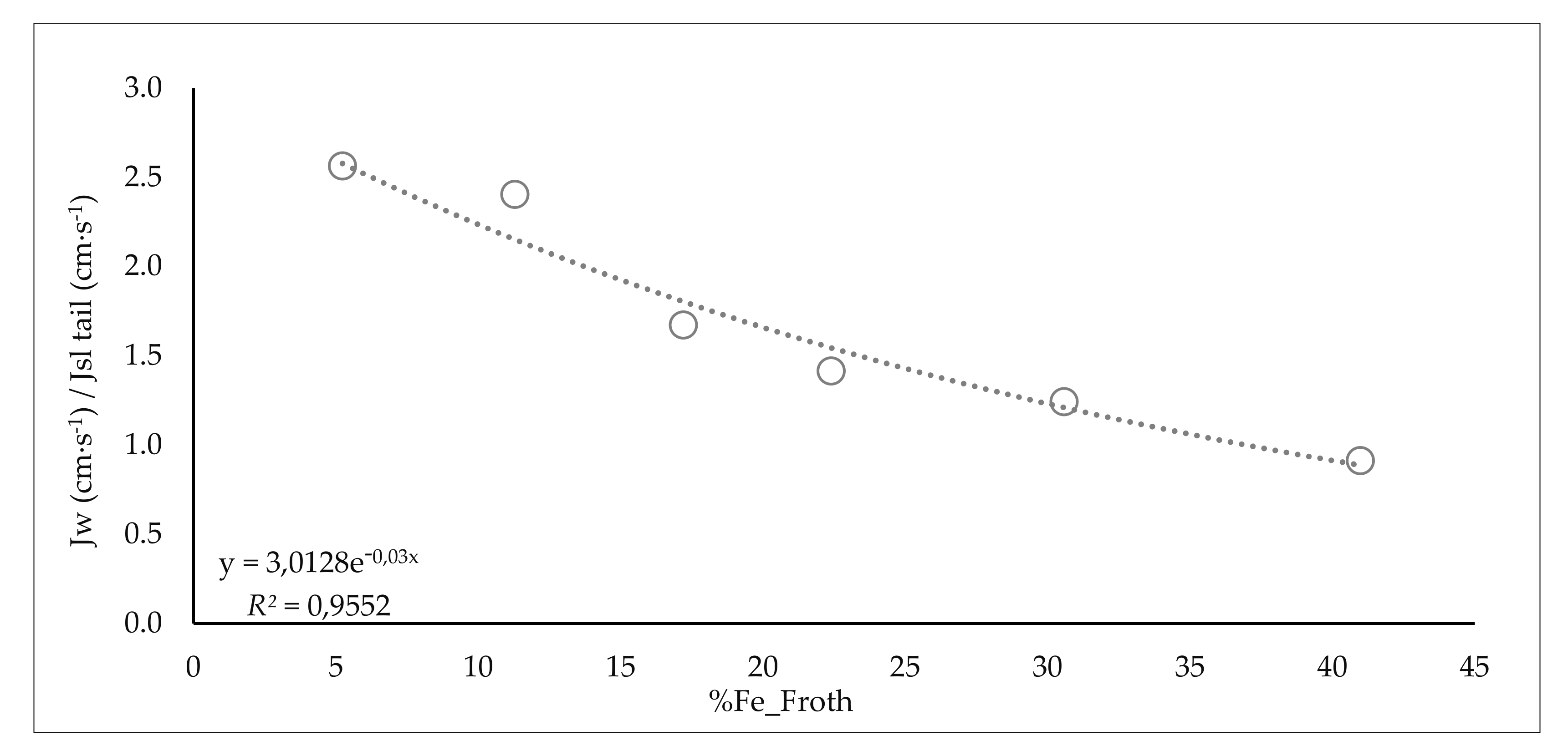
| Range Collector (g/m3 water_feed)/(%SiO2) | %SiO2 Product | %Water Froth | Range Fe Froth % | %Water Recovery_Froth | JW/JSL Tail | ||
|---|---|---|---|---|---|---|---|
| from 0 to 0.75 | 0.6 | 25.1 | 75.7 | from 0 to 7 | 5.2 | 12.4 | 2.6 |
| from 0.75 to 1.85 | 1.5 | 19.2 | 77.8 | from 7 to 14 | 11.3 | 18.3 | 2.4 |
| from 1.85 to 2.95 | 2.2 | 19.0 | 81.7 | from 14 to 21 | 17.2 | 25.0 | 1.7 |
| from 2.95 to 4.05 | 3.3 | 14.0 | 82.6 | from 21 to 28 | 22.4 | 28.8 | 1.4 |
| from 4.05 to 5.15 | 4.2 | 14.1 | 87.5 | from 28 to 35 | 30.6 | 34.9 | 1.2 |
| from 5.15 to 6.25 | 5.7 | 11.2 | 87.0 | from 35 to 42 | 41.0 | 66.3 | 0.9 |
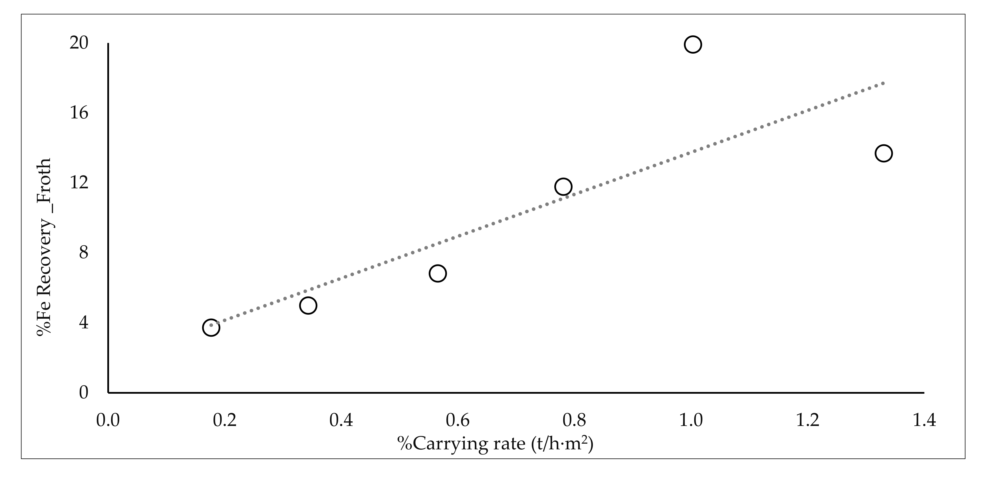
| Range Water Recovery_Product % | %Recovery Fe_Product | Range Carrying Rate (t/h·m2) | %Fe Recovery Froth | %SiO2 Product | |||
| from 0 to 0.8 | 0.7 | 87.2 | from 0 to 0.23 | 0.2 | 3.7 | 22.3 | |
| from 0.8 to 1.6 | 1.2 | 91.4 | from 0.23 to 0.46 | 0.3 | 5.0 | 23.5 | |
| from 1.6 to 2.4 | 1.9 | 91.5 | from 0.46 to 0.69 | 0.6 | 6.8 | 19.2 | |
| from 2.4 to 3.2 | 3.0 | 94.1 | from 0.69 to 0.92 | 0.8 | 11.8 | 14.2 | |
| from 3.2 to 4 | 3.7 | 98.3 | from 0.92 to 1.15 | 1.0 | 19.9 | 11.7 | |
| - | - | - | - | from 1.15 to 1.38 | 1.3 | 13.7 | 11.2 |
Publisher’s Note: MDPI stays neutral with regard to jurisdictional claims in published maps and institutional affiliations. |
© 2021 by the authors. Licensee MDPI, Basel, Switzerland. This article is an open access article distributed under the terms and conditions of the Creative Commons Attribution (CC BY) license (https://creativecommons.org/licenses/by/4.0/).
Share and Cite
Filippov, L.O.; Silva, K.; Piçarra, A.; Lima, N.; Santos, I.; Bicalho, L.; Filippova, I.V.; Peres, A.E.C. Iron Ore Slimes Flotation Tests Using Column and Amidoamine Collector without Depressant. Minerals 2021, 11, 699. https://doi.org/10.3390/min11070699
Filippov LO, Silva K, Piçarra A, Lima N, Santos I, Bicalho L, Filippova IV, Peres AEC. Iron Ore Slimes Flotation Tests Using Column and Amidoamine Collector without Depressant. Minerals. 2021; 11(7):699. https://doi.org/10.3390/min11070699
Chicago/Turabian StyleFilippov, Lev O., Klaydison Silva, Alexandre Piçarra, Neymayer Lima, Iranildes Santos, Leandro Bicalho, Inna V. Filippova, and Antonio Eduardo Clark Peres. 2021. "Iron Ore Slimes Flotation Tests Using Column and Amidoamine Collector without Depressant" Minerals 11, no. 7: 699. https://doi.org/10.3390/min11070699
APA StyleFilippov, L. O., Silva, K., Piçarra, A., Lima, N., Santos, I., Bicalho, L., Filippova, I. V., & Peres, A. E. C. (2021). Iron Ore Slimes Flotation Tests Using Column and Amidoamine Collector without Depressant. Minerals, 11(7), 699. https://doi.org/10.3390/min11070699