Article

CFD Modeling and Simulation of the Hydrodynamics Characteristics of Coarse Coal Particles in a 3D Liquid-Solid Fluidized Bed

1
School of Minerals Processing and Bioengineering, Central South University, Changsha 410083, China
2
Key Laboratory of Hunan Province for Clean and Efficient Utilization of Strategic Calcium-Containing Mineral Resources, Central South University, Changsha 410083, China
3
College of Chemistry and Chemical Engineering, Central South University, Changsha 410083, China
*
Authors to whom correspondence should be addressed.
Minerals 2021, 11(6), 569; https://doi.org/10.3390/min11060569
Submission received: 24 April 2021 / Revised: 19 May 2021 / Accepted: 24 May 2021 / Published: 27 May 2021

Abstract

:
In this study, a Eulerian-Eulerian liquid-solid two-phase flow model combined with kinetic theory of granular flow was established to study the hydrodynamic characteristics and fluidization behaviors of coarse coal particles in a 3D liquid-solid fluidized bed. First, grid independence analysis was conducted to select the appropriate grid model parameters. Then, the developed computational fluid dynamics (CFD) model was validated by comparing the experimental data and simulation results in terms of the expansion degree of low-density fine particles and high-density coarse particles at different superficial liquid velocities. The simulation results agreed well with the experimental data, thus validating the proposed CFD mathematical model. The effects of particle size and particle density on the homogeneous or heterogeneous fluidization behaviors were investigated. The simulation results indicate that low-density fine particles are easily fluidized, exhibiting a certain range of homogeneous expansion behaviors. For the large and heavy particles, inhomogeneity may occur throughout the bed, including water voids and velocity fluctuations.

Graphical Abstract

1. Introduction

Coal is a primary energy source for industrial development, and it is usually processed by gravity separation and flotation, which are highly dependent on coal particle size. However, for coarse slime with a large particle size range, both gravity separation and flotation have poor separation effects [1,2]. To solve this problem, liquid-solid fluidized beds (LSFBs) have been employed as a powerful approach for clean coarse slime separation owing to advantages such as low energy consumption and simple operation. However, gaining a deeper understanding of LSFBs with complicated multi-phase flow characteristics and multi-scale properties is difficult [3,4].
In recent decades, fluidization technology has been widely applied in polymerization, mineral/coal separation, pneumatic conveying, and other fields [5,6,7,8,9]. It is also employed to separate and recover coarse particles in the mineral processing industry [10,11]. Liquid-solid fluidization is a process in which particles (acting as a solid phase) are suspended in liquid due to the action of drag force [12]. The LSFB exhibits unique liquid-solid contact characteristics and has numerous advantages, such as fast mass transfer, high contact conversion efficiency, and good heat transfer performance. After the developments in recent decades, liquid-solid fluidization technology has been applied in numerous industries, such as water treatment and mineral processing [13]. In the mineral processing industry, fluidization technology is generally employed to separate minerals with different physical and chemical properties, such as particle size, density, and grade. Researchers intend to improve the efficiency of mineral particle separation in an LSFB by enhancing the cognition of particle fluidization behavior [14,15,16,17].
LSFB modeling is challenging owing to its complex flow behavior and liquid-solid interactions. In recent decades, with the rapid development of computer technology and the progress of multi-phase flow model research [18,19,20,21], computational fluid dynamics (CFD) simulation has become a powerful tool for studying the particle flow characteristics in fluidized beds [22,23,24,25,26,27]. In general, two types of CFD models are often employed in the multiphase flow simulations: Eulerian-Lagrangian models and Eulerian-Eulerian models. In the Eulerian-Lagrangian model, the fluid phase is treated as a continuum by solving the Navier-Stokes equations, while the dispersed phase is solved by tracking a large number of particles, bubbles, or droplets through the flow field. The dispersed phase can exchange momentum, mass, and energy with the fluid phase. The advantage of using this approach is that each particle trajectory, as well as the system parameters, is known exactly. The results often provide physical insight into the nature of the flow. However, because a large number of particle trajectories are needed to determine the average behavior of a system, the computational requirements are extremely high. The Eulerian–Eulerian approach, or a two-fluid model, is generally adopted in engineering simulations. In this method, different phases are treated mathematically as interpenetrating continua. Conservation equations for each phase are derived, having similar structure for all phases. In the case of particulate flows, the kinetic theory of the granular phase is used to estimate the solid viscosity and solid stresses, and incorporates it into the two-fluid model. In the case of two-phase flow in fluidized beds where the number of solid particles is large, the E-E approach is the more attractive and practical method. In this study, due to the high-volume fraction of solids in LSFB, the Eulerian method was employed owing to its low demand for computing resources. The complete interpenetration of liquid phase and solid phase is considered in the momentum equation [28,29,30]. The kinetic theory of granular flow (KTGF) is used to calculate solid phase properties and achieve closure. The mass and momentum conservation equations of the two phases are obtained from the statistical average of the instantaneous local transport equations [31].
In addition, numerous experimental investigations were conducted to understand the hydrodynamic characteristics of the LSFB flotation cell [10,32,33,34,35]. Di Felice [36] investigated the heterogeneous characteristics of liquid-solid fluidized beds where the degree of heterogeneous behavior is highly dependent on particle morphology, particle size distribution, and the fluid-to-solid density ratio. Generally, small particles with low density are more easily fluidized compared with large and heavy particles. The explanations can be found by analyzing the gravitational pull and interparticle forces acting on the particles [37]. For large particles, inhomogeneity phenomena may occur in the whole bed, including particle aggregation, water voids and velocity fluctuations, due to bubble and jet effects. However, there are still many difficulties in the modeling of liquid-solid fluidized beds, owing to the complex flow behavior and liquid-solid interactions, especially the inhomogeneity fluidization phenomena. Therefore, a detailed insight into the homogeneities or heterogeneous behavior hydrodynamics in liquid-solid fluidization systems is significant to obtain a better understanding of fluidization flotation and a better design of an efficient operation.
The research object of this study is the hydrodynamic characteristics of coarse coal particles in a 3D LSFB. The Eulerian–Eulerian two-fluid model combined with KTGF was employed to study the fluidization behavior of coarse coal particles. In this study, much attention was paid to the inhomogeneity fluidization in liquid-solid fluidized beds. The effects of particle size and particle density on the homogeneous or heterogeneous fluidization behaviors were investigated by means of CFD modeling and simulation. The simulation results indicate that low-density fine particles are easily fluidized, exhibiting a certain range of homogeneous expansion behaviors. For the large and heavy particles, inhomogeneity may occur throughout the bed, including water voids and velocity fluctuations.

2. CFD Mathematical Model Development

As previously mentioned, the fluidization of coarse coal particles is a typical liquid-solid system in which the particle mixing quality is important. In this study, the Euler-Euler liquid-solid two-phase flow model was used to obtain the local coarse coal particle fluidization characteristics. The detailed model equations include the continuity equation, momentum equation, KTGF model, drag model and turbulent model.

2.1. CFD-KTGF Model

The continuity equation is expressed as follows:
t ( α q ρ q ) + ( α q ρ q v q ) = 0 , q = l , s , α l + α s = 1
The momentum equations are expressed as
t ( α l ρ l v l ) + ( α l ρ l v l v l ) = α l p + τ ¯ ¯ l + K s l ( v s v l ) + α l ρ l g + ( F l + F l i f t , l )
t ( α s ρ s v s ) + ( α s ρ s v s v s ) = α s p p s + τ ¯ ¯ s + K s l ( v l v s ) + α s ρ s g + ( F s + F l i f t , s )
τ ¯ ¯ q = α q μ q ( v q + v q T ) + α q ( λ q 2 3 μ q ) · v q I ¯ ¯
Equation (4) is used to calculate the stress tensor. Notably, solid pressure and viscosity are introduced in the momentum equation when the particle phase is regarded as the continuous phase according to the Eulerian method. To achieve closure, Lun et al. [38] derived the KTGF model based on the kinetic theory of gases. In the KTGF model, the granular temperature is defined to consider the conservation of solid energy fluctuations. The equation for the granular temperature is expressed as
3 2 [ t ( α s ρ s Θ s ) + ( α s ρ s v s Θ s ) ] = ( κ Θ s Θ s ) + ( p s I + τ s = ) : v s γ Θ s 3 K l s Θ s
In Equation (5), κ Θ s and γ Θ s denote the diffusion coefficient and collisional dissipation of energy, respectively.
κ Θ s = 15 d s ρ s α s Θ s π 4 ( 41 33 η ) [ 1 + 12 5 η 2 ( 4 η 3 α s g 0 ) + 16 15 π ( 41 33 η ) η α s g 0 ]
γ Θ s = 12 ( 1 e s s 2 ) g 0 d s π ρ s α s 2 Θ s 1.5
η = 0.5 ( 1 + e s s )
g 0 = [ 1 ( α s / α s , max ) 1 / 3 ] 1
The solid-phase properties can be calculated by using the granular temperature equation.
Solid pressure:
p s = α s ρ s Θ s + 2 ρ s ( 1 + e s s ) α s 2 g 0 Θ s
Solid shear viscosity:
μ s = μ s , c o l + μ s , k i n + μ s , f r
μ s , c o l = 4 5 α s ρ s d s g o ( 1 + e s s ) ( Θ s π ) 0.5
μ s , k i n = 5 d s ρ s Θ s π 48 α s ( 1 + e s s ) g 0 [ 1 + 4 5 ( 1 + e s s ) α s g 0 ] 2
μ s , f r = p s sin θ 2 I 2 D
Solid bulk viscosity:
λ s = 4 3 d s ρ s α s g 0 ( 1 + e s s ) ( Θ s π ) 0.5

2.2. Turbulent Model

In this study, the superficial liquid velocity was less than 0.025 m/s and the particle size was less than 1.75 mm, which led to a small-particle Reynolds number (<50), which is known as a transitional flow regime. In this case, Menter [39] developed the shear-stress transport k–ω model incorporated with low Reynolds number modifications to calculate the turbulent viscosity. The detailed equations are given as follows:
t ( α l ρ l k ) + x i ( α l ρ l k v l ) = x j ( Γ k k x j ) + α l ( G k Y k + S k )
t ( α l ρ l ω ) + x i ( α l ρ l ω v l ) = x j ( Γ ω ω x j ) + α l ( G ω Y ω + D ω + S ω )
Equations (16) and (17) are used to calculate the turbulence kinetic energy (k) and specific dissipation rate (ω), which are then employed to calculate the turbulent viscosity:
μ t = α ρ k ω
where α denotes the low Reynolds number correction factor.
α = α ( 0.024 + Re t / 6 1 + Re t / 6 )
Re t = ρ k μ ω

2.3. Interphase Force Models

The interphase force includes the drag force, lift force, turbulence dispersion force and virtual mass force. Zbib et al. [40] developed a coupled computational fluid dynamics (CFD) and discrete element method (DEM) model to analyze the fluid-particle and particle–particle interactions in a 3D liquid-solid fluidized bed. They investigated the effect of drag force, pressure gradient, virtual mass, and Saffman lift forces. The drag force was observed to be considerably greater in magnitude in comparison to other interaction forces. This signified the drag force’s dominance, in terms of its influence on the macroscopic behavior of liquid-solid fluidized beds, in comparison to other interaction forces. Therefore, in this study, we only considered the drag and lift forces, and the others (e.g., virtual mass) were negligible. The Gidaspow drag model and Moraga lift force model were used in the CFD simulation.

2.3.1. Gidaspow Drag Force Model

K s l = 3 4 C D α s α l ρ l | v s v l | d s α l 2.65 α l > 0.8
K s l = 150 α s ( 1 α l ) μ l α l d s 2 + 1.75 ρ l α s | v s v l | d s α l 0.8
C D = 24 α l Re s [ 1 + 0.15 ( α l Re s ) 0.687 ]
Re s = α s d s ρ l | v s v l | μ l

2.3.2. Moraga Lift Force Model

In the momentum equation, the lift force ( F l i f t ) is added to both phases and is expressed as
F l i f t , s = C l ρ l α s ( v l v s ) × ( × v l )
In Equation (25), C l denotes the lift coefficient. Based on the Moraga lift force model, the lift force coefficient is expressed as
C l = { 0.0767 φ 6000 ( 0.12 0.2 e φ 3.6 × 10 5 ) e φ 3 × 10 7 6000 < φ < 5 × 10 7 0.6353 φ 5 × 10 7
where φ = Re s Re w . Re s and Re w denote the particle Reynolds number and vorticity Reynolds number, respectively.
Re s = ρ l ( v l v s ) d s μ l
Re w = ρ l ( × v l ) d s 2 μ l

3. Simulation Details

Figure 1 shows the 3D LSFB mesh. ANSYS ICEM software 19.0 was used to develop and mesh a 3D LSFB. The 3D fluidized bed is divided into two parts. The lower part (Part II) was divided by an unstructured grid. The unstructured unit had a maximum size of 1 mm. The bottom of the fluidized bed was considered as the distribution plate on which some small holes were evenly arranged. The small holes had a diameter of 2 mm and the opening rate of the bottom distribution plate was 40%. To ensure that there was sufficient mesh number on the small holes, the mesh was densified at the small holes and the maximum size of the mesh on the small holes was set to 0.5 mm. Conversely, the upper part (Part I) was meshed by structural elements with a mesh size of 2 mm. The purpose was to reduce the calculation cost and stabilize the numerical calculation. In the CFD simulation, the water and coal particles were defined as the primary phase and secondary phase, respectively. At the bottom of the fluidized bed, which had an initial height of H0 (100 mm), the coal particles were initially patched. The boundary conditions can be classified into velocity inlet (small holes at the bottom of the bed), pressure outlet, and wall in the fluidized bed reactor; the rest of the bottom plate which is not velocity inlet uses a wall BC.
For the numerical simulation, both the cell size and time step should be prudently selected. In this study, the water velocity was 0.25–2.5 cm/s and the time step was 0.005 s. As can be seen from Equation (29), with this time step, the Courant number was 0.0125–0.125, which is a reasonable value accepted by numerous researchers [41]. The foregoing conditions were applied in all the CFD simulations in this study.
N c = v l Δ t Δ c e l l
In this study, the root-mean-square error (RMSE), expressed by Equation (30), was used to evaluate the deviation between the CFD simulation results and experimental data.
RMSE = 1 n ( y i y i ) 2 n
where y i denotes the CFD simulation results, y i is the experimental data, and n is the number of experiments. The RMSE values were 3.65 for low-density fine particles, and 2.01 for high-density coarse particles. The calculated RMSE values were acceptable, thus ensuring the accuracy of the CFD results.
The developed CFD mathematical model was solved using ANSYS Fluent software where the equations were discretized using the second-order upwind method. The SIMPLE algorithm was employed to couple velocity and pressure. The low-relaxation-factor method was employed to facilitate the convergence. The under-relaxation factors were 0.3 for pressure, 0.7 for momentum, 0.3 for volume fraction, 0.2 for granular temperature, and default values for the other parameters. All the CFD simulations were performed on a 2.2 GHz Intel 2 16-core central processing unit with 128 GB of RAM located in Beijing, China.

4. Results and Discussion

4.1. Grid Dependence Analysis

Generally, the accuracy of a CFD simulation results depends on the density of the geometric grid [42,43,44,45]. For this purpose, the grid sensitivity of four different grid resolutions with node numbers of 307,281 (coarse), 454,982 (coarse), 639,560 (medium) and 829,680 (fine) were used for the initial numerical simulation. Figure 2 presents the contours of the solid volume fraction at a time of 50 s. Figure 3 presents the time-averaged solid volume fractions along the bed height, and the bed height versus the simulation time for the different grids at vl = 0.0125 m/s, ρs = 1.4–1.5 kg/m3 and ds = 0.85 ± 0.15 mm, whereas the Gidaspow equations [31] were used as the drag model.
The effects of the grid on the contours of the solid volume fraction at the time of 50 s are presented in Figure 2. The simulation results under the four grids almost exhibited similar trends in terms of the volume fraction of the solid phase, especially in a bed height above 0.05. In addition, both the final bed expansion height and flow state were similar, although slight differences in the particle concentration distribution were observed at the bottom of the bed. For the medium and fine meshes, the local solid-phase volume fractions throughout the bed remained almost the same.
The effect of the grid on the volume fraction of the solid particles along the bed height is presented in Figure 3A. In the case of a coarse grid, the particle volume fraction presented a smaller distribution fluctuation profile due to numerical diffusion. No obvious difference was observed between the medium and fine grids.
In Figure 3B, the bed height sharply increases at the start of fluidization (<25 s). With the increase in flow time, the bed height is approximately constant and stable. The bed height profiles are similar for the medium and fine meshes, whereas for the coarse mesh, significant differences are observed. As can be seen from the figure, the coarse mesh may have a higher predictive value of the bed height. When compared with the experimental data, the relative error of the bed height predicted by the medium and fine meshes is about 3.85%, and that predicted by the coarse mesh is 5.77%.
Based on these evaluations, to balance accuracy and computational efficiency, the results in Figure 2 and Figure 3 indicate that the selected 639,560 grids for the simulation are sufficient for the fluid dynamic prediction of LSFBs.

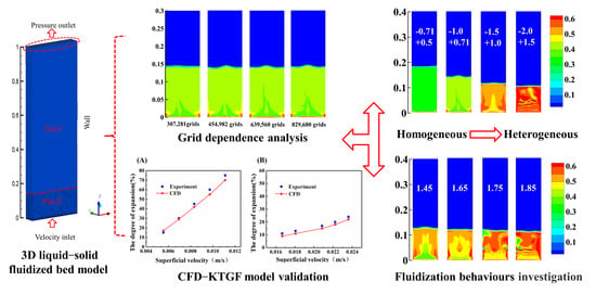
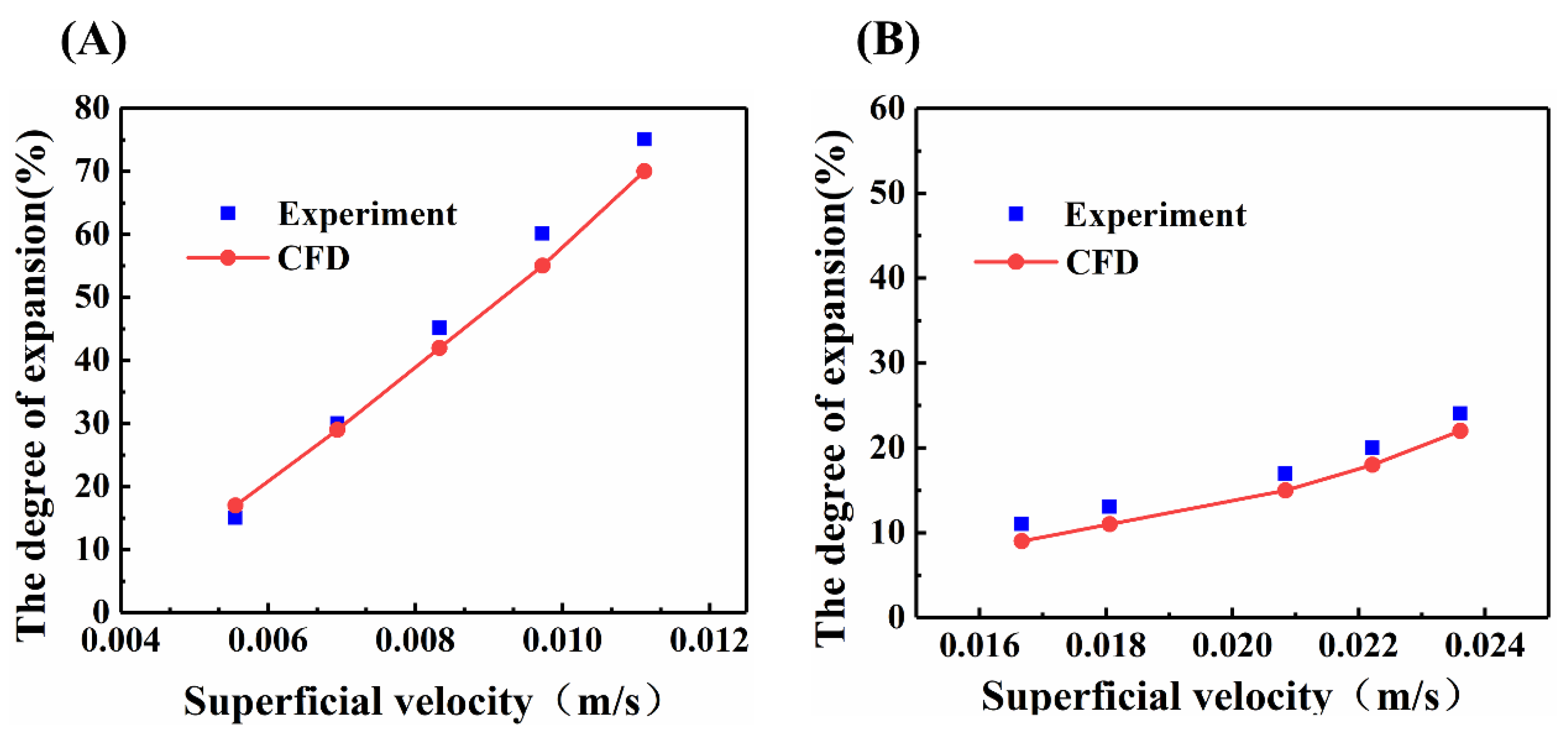
4.2. Model Validation

The performance of the proposed CFD mathematical model was validated by comparing it with the experimental data and the CFD simulation results in terms of the bed expansion height. In this study, two coal particles were selected: one was a small and light particle, with a density of 1400–1500 kg/m3 and size of 0.6 ± 0.1 mm; the other was a large and heavy particle with a density of 1700–1800 kg/m3 and size of 1.75 ± 0.25 mm. The comparisons of the expansion degree were performed at different velocities.
Wang [46] conducted numerous bed expansion experiments under the conditions of different particle size, particle density and superficial liquid velocity LSFBs. Their experimental data of the bed expansion height were used to validate our CFD mathematical model. Table 1 presents the detailed parameters of the experimental conditions and experimental results. In this study, the CFD simulations were conducted under the same operating conditions and using the structural parameters of the LSFB, so that the particle expansion degrees of the CFD results and experimental data are comparable. It is worth noting that simulations and experimental comparisons of low-density fine particles and high-density coarse particles were performed. Figure 4 presents variation of the bed expansion with superficial liquid velocity.
As can be seen from Figure 4, the degree of bed expansion is highly dependent on the apparent flow rate of the liquid. In Figure 4A, when the superficial liquid velocity increased from 0.0056 to 0.0111 m/s for the low-density (1400–1500 kg/m3) and fine (0.6 ± 0.1 mm) coal particles, the bed expansion degree increased from 15% to 75%. However, as presented in Figure 4B, the bed expansion degree increased from 11% to 24% for the high-density (1600–1700 kg/m3) and coarse particles (1.75 ± 0.25 mm) when the superficial liquid velocity increased from 0.0167 to 0.0236 m/s. A higher critical fluidization velocity was observed for high-density coarse particles. In addition, the growth rate of the bed expansion height with the increase in liquid velocity was dependent on the particle properties. The predicted bed height is also presented in Figure 4. As can be seen from the figure, the CFD simulation results are in good agreement with the experimental data.

4.3. Model Application

In this section, the influences of some key operational parameters, such as particle size and particle density, on the hydrodynamic characteristics and homogeneous or heterogeneous fluidization behaviors in liquid-solid fluidization systems are investigated based on the validated model.

4.3.1. Effect of Coal Particles Size

Figure 5 shows instantaneous snapshots of the solid-phase volume fraction under the condition of different particle sizes (0.6 ± 0.1, 0.85 ± 0.15, 1.25 ± 0.25 and 1.75 ± 0.25 mm) at the same flow rate of 1.25 cm/s and particle density of 1400–1500 kg/m3. As presented in Figure 5A, when the size of the solid coal particles is within the range of 0.6 ± 0.1 mm, the consistent color in the figure indicates that the local volume fraction of the particles is homogeneous throughout the column. Generally, when the particle size is relatively low, the liquid flow along the fluidized bed is stable and very regular and the particle flow is small and symmetric, which is conducive to the realization of homogeneous flow. However, as the coal particle size increases, the bed expansion height experiences a significant decrease (see Figure 5A–C). The resistance of the fluid to the particles increases as the particle size increases, which results in heterogeneous fluidization in the bed. Moreover, in the radial direction of the bed, the volume fraction of the central solid phase is low, whereas the volume fraction of the near-wall solid phase is high. This is because the particles rise in the central region and fall near the wall at a lower speed. From Figure 5D, it can also be seen that the expansion height of the bed decreases as the diameter of the solid particles increases. Especially in the range of 1.75 ± 0.25 mm, the bed homogeneity worsens, thus disturbing the regularity of the flow state.
Figure 6 presents the time evolution of the bed expansion height. As can be seen from the figure, the whole fluidization process can be divided into two stages. In the first stage, the bed expansion height almost increases linearly with the flow time. Then, it remains stable at a constant value after 35 s for four different particle sizes. When the particle size increases from 0.6 ± 0.1 to 1.75 ± 0.25 mm, the bed expansion height decreases correspondingly from 0.18 to 0.105 m.

4.3.2. Effect of Coal Particle Densities

This section discusses the effects of particle density (1400–1500, 1600–1700, 1700–1800 and 1800–1900 kg/m3) on the fluidization characteristics of coal particles. Figure 7 presents the time evolution of solid-phase holdup. As can be seen from the figure, the bed expansion height decreased from 0.13 to 0.115 m when the coal particle density increased from 1400–1500 to 1800–1900 kg/m3. From Figure 7A,B, it can be seen that the fluidized bed reached a stable fluidized state after 40 s. In the radial direction of the bed, the volume fraction of the central solid phase was low, whereas the volume fraction of the near-wall solid phase was high. This is because the particles rise in the central region and fall near the wall at a lower speed, which results in the tendency of the particles to stay near the wall for a longer time. When the coal particle density increases to 1700−1800 and 1800−1900 kg/m3, heterogeneous fluidization can be observed (see Figure 7C,D).
Figure 7 shows the time evolutions of the volume fraction of the solid phase under the condition of different coal particle densities. The observed horizontal stripes in particle volume fraction contours are liquid voids, which are similar to the bubbles in gas-solid fluidization systems. With the increase in particle density, the particle phase tends to concentrate at the bottom of the fluidized bed, and the characteristic flow feature is the void motion of the liquid phase. Generally, there are two regions along the bed height: a dense bed at the bottom and a dilute bed at the top. In this regard, Renganathan and Krishnaiah [47] found void motions in liquid-solid fluidized beds at high superficial liquid velocities. It is easy to understand that the increased liquid phase volume fraction improves the homogeneity of the particle phase due to the increased voidage distance among the particles. Similar results were also reported by Wang et al. [48]. In this study, however, the generated void may have been caused by the increased effect of gravity on the particles. As shown in Figure 7, when the particle density was increased to 1800–1900 kg/m3, the particles were practically unfluidized, despite the presence of many voids in the bed.
Figure 8 presents the time evolution of the bed expansion height. In the first 10 s, the bed expansion height significantly increased for all the coal particles with different densities. However, from 10 to 25 s, a decrease in the bed expansion height was then observed. After 25 s, the bed height finally stabilized at a constant value as the flow time increased. This phenomenon can be explained by the formation and movement of vacuoles, which lead to the fluctuation of the bed expansion height.

5. Conclusions

The fluidization behavior of coal particles in a 3D liquid-solid fluidized bed (LSFB) was investigated by using a Eulerian–Eulerian model combined with the KTGF. First, grid dependence analysis was conducted to select the appropriate grid model parameters. The CFD simulation results and experimental data of the bed expansion degree were compared at different superficial liquid velocities to validate the performance of the proposed CFD mathematical model. The simulation results of low-density fine particles and high-density coarse particles indicated that the RMSE values were 3.65 and 2.01, respectively.
The validated CFD model was then used to investigate the effects of particle size and particle density on the hydrodynamic characteristics and homogeneities or heterogeneous fluidization behaviors in a 3D LSFB. When the particle size increased from 0.6 ± 0.1 to 1.75 ± 0.25 mm, the bed expansion height decreased from 0.18 to 0.105 m. A homogeneous fluidization phenomenon was observed for the coal particle with a size of 0.6 ± 0.1 mm, and heterogeneous fluidization occurred as the particle size increased. The particle density also plays an important role in determining the fluidization behaviors. When the coal particle density increased from 1400−1500 to 1800−1900 kg/m3, the bed expansion height decreased from 0.13 to 0.115 m. It was observed that the bed expansion height fluctuated with flow time due to the formation and movement of vacuoles. The simulation results indicated that the small and light particles are easily fluidized, thus exhibiting a certain range of homogeneous expansion behaviors. For the large and heavy particles, inhomogeneity may occur throughout the bed, including water voids and velocity fluctuations caused by vacuoles.

Author Contributions

Conceptualization, J.P.; Formal analysis, J.P.; Investigation, J.P.; Methodology, J.P.; Project administration, W.S.; Software, J.P.; Supervision, H.H. and L.X.; Validation, J.P.; Visualization, J.P.; Writing—Original draft preparation, J.P.; Writing—Review and Editing, H.H. and L.X. All authors have read and agreed to the published version of the manuscript.

Funding

This research received no external funding.

Data Availability Statement

Not applicable.

Acknowledgments

The authors are grateful for the financial support from the Key Laboratory of Hunan Province for Clean and Efficient Utilization of Strategic Calcium-containing Mineral Resources (No. 2018TP1002), National 111 Project (No. B14034), Collaborative Innovation Centre for Clean and Efficient Utilization of Strategic Metal Mineral Resources, National Key Scientific Research Project (2018YFC1901601, 2018YFC1901602, and 2018YFC1901605), Innovation Driven Plan of Central South University (No. 2015CX005), and the Fundamental Research Funds for the Central Universities of Central South University(No. 2020zzts204).

Conflicts of Interest

The authors declare no conflict of interest.

Nomenclature

C D Drag coefficient
C l Lift force coefficient
d s Diameter of particles, m
e Particle–particle restitution coefficient
DDiffusion coefficient, m2·s
F The liquid-solid interphase force, N·m−3
g Gravitational acceleration, m·s−2
g 0 Radial distribution function
G i The product term in turbulence model
H Bed expansion height, m
I Unit tensor
k Turbulence kinetic energy, m2·s−2
k Θ Diffusion coefficient, m2·s−1
K s l Interphase exchange coefficient, kg·m2·s−1
N c Courant number
p Pressure, Pa
Re Reynolds number
S i Source term in the turbulence model
t Time, s
v Velocity, m·s−1
Y i Dissipation terms in the turbulence model
α Volume fraction
ρ Density, kg·m−3
τ ¯ ¯ Stress tensor, Pa
μ Viscosity, Pa·s
ε Voidage
Θ Granular temperature, m2·s−2
λ s Solid bulk viscosity, Pa·s
ω Specific dissipation rate, s−1
κ Thermal conductivity, W·m−1 K−1
η Efficiency of energy transfer from the liquid phase to the solid phase, %
γ The collisional dissipation energy, kg·m−1 s−3

References

  1. Xia, W.; Yang, J.; Zhao, Y.; Zhu, B.; Wang, Y. Improving floatability of taixi anthracite coal of mild oxidation by grinding. Physicochem. Probl. Miner. Process. 2012, 48, 393–401. [Google Scholar]
  2. Xia, W. The effect of coarse gangue particles during the coal flotation process. Energy Sources Part A Recovery Util. Environ. Eff. 2016, 38, 3001–3005. [Google Scholar] [CrossRef]
  3. Tang, L. Characteristics of fluidization and dry-beneficiation of a wide-size-range medium-solids fluidized bed. Int. J. Min. Sci. Technol. 2017, 27, 467–471. [Google Scholar] [CrossRef]
  4. Su, D.; Luo, Z.; Lei, L.; Zhao, Y. Segregation modes, characteristics, and mechanisms of multi-component lignite in a vibrated gas-fluidized bed. Int. J. Min. Sci. Technol. 2018, 28, 251–258. [Google Scholar] [CrossRef]
  5. He, J.; Zhao, Y.; Huang, G.; Liu, C. Evaluation of the separation performance of an air dense medium gas-solid fluidized bed for coal cleaning: Effect of the binary dense media. Adv. Powder Technol. 2018, 29, 3265–3273. [Google Scholar] [CrossRef]
  6. Jiang, H.; Huang, L.; Lu, Q.; Zhao, Y.; Luo, Z.; Duan, C.; Dong, L.; Chen, Z.; Lv, B.; Zhao, J.; et al. Separation performance of coal in an air dense medium fluidized bed at varying feeding positions. Fuel 2019, 243, 449–457. [Google Scholar] [CrossRef]
  7. Zhu, X.; Dong, P.; Tu, Q.; Zhu, Z.; Yang, W.; Wang, H. Investigation of gas-solid flow characteristics in the cyclone dipleg of a pressurised circulating fluidised bed by ect measurement and cpfd simulation. Meas. Sci. Technol. 2019, 30, 054002. [Google Scholar] [CrossRef]
  8. Ma, T.; Fan, C.; Hao, L.; Li, S.; Jensen, P.A.; Song, W.; Lin, W.; Dam-Johansen, K. Biomass ash induced agglomeration in fluidized bed. Part 2: Effect of potassium salts in different gas composition. Fuel Process. Technol. 2018, 180, 130–139. [Google Scholar] [CrossRef]
  9. Wang, S.; Yang, X.; Xu, S.; Zhang, K.; Li, B. Evaluation of sorption-enhanced reforming of biodiesel by-product in fluidized beds by means of cfd approach. Fuel 2018, 214, 115–122. [Google Scholar] [CrossRef]
  10. Fosu, S.; Awatey, B.; Skinner, W.; Zanin, M. Flotation of coarse composite particles in mechanical cell vs. the fluidised-bed separator (the hydrofloat™). Miner. Eng. 2015, 77, 137–149. [Google Scholar] [CrossRef]
  11. Wyslouzil, H.E.; Kohmeunch, J.; Christodoulou, L.; Fan, M. Coarse and fine particle flotation. In Proceedings of the 48th Conference of Metallurgists, Niagara, ON, Canada, 22 November 2009. [Google Scholar]
  12. Razzak, S.A.; Barghi, S.; Zhu, J.X. Axial hydrodynamic studies in a gas-liquid-solid circulating fluidized bed riser. Powder Technol. 2010, 199, 77–86. [Google Scholar] [CrossRef]
  13. Atta, A.; Razzak, S.A.; Nigam, K.D.P.; Zhu, J.X. (gas)-liquid-solid circulating fluidized bed reactors: Characteristics and applications. Ind. Eng. Chem. Res. 2009, 48, 7876–7892. [Google Scholar] [CrossRef]
  14. Steiner, H.J. A contribution to the theory of jigging, part i: Similarity criteria of the motion of jig layers. Miner. Eng. 1996, 9, 675–686. [Google Scholar] [CrossRef]
  15. Mishra, B.K.; Mehrotra, S.P. A jig model based on the discrete element method and its experimental validation. Int. J. Miner. Process. 2001, 63, 177–189. [Google Scholar] [CrossRef]
  16. Galvin, K.P.; Pratten, S.J.; Lambert, N.; Callen, A.M.; Lui, J. Influence of a jigging action on the gravity separation achieved in a teetered bed separator. Miner. Eng. 2002, 15, 1199–1202. [Google Scholar] [CrossRef]
  17. Mukherjee, A.K.; Mishra, B.K. Experimental and simulation studies on the role of fluid velocity during particle separation in a liquid-solid fluidized bed. Int. J. Miner. Process. 2007, 82, 211–221. [Google Scholar] [CrossRef]
  18. Ding, J.; Gidaspow, D. A bubbling fluidization model using kinetic theory of granular flow. AIChE J. 1990, 36, 523–538. [Google Scholar] [CrossRef]
  19. Sinclair, J.L.; Jackson, R. Gas-particle flow in a vertical pipe with particle-particle interactions. AIChE J. 1989, 35, 1473–1486. [Google Scholar] [CrossRef]
  20. Hartge, E.-U.; Ratschow, L.; Wischnewski, R.; Werther, J. Cfd-simulation of a circulating fluidized bed riser. Particuology 2009, 7, 283–296. [Google Scholar] [CrossRef]
  21. Wang, W.; Lu, B.; Zhang, N.; Shi, Z.; Li, J. A review of multiscale cfd for gas-solid cfb modeling. Int. J. Multiph. Flow 2010, 36, 109–118. [Google Scholar] [CrossRef]
  22. He, Y.; Yan, S.; Wang, T.; Jiang, B.; Huang, Y. Hydrodynamic characteristics of gas-irregular particle two-phase flow in a bubbling fluidized bed: An experimental and numerical study. Powder Technol. 2016, 287, 264–276. [Google Scholar] [CrossRef]
  23. Hua, L.; Zhao, H.; Li, J.; Wang, J.; Zhu, Q. Eulerian-eulerian simulation of irregular particles in dense gas-solid fluidized beds. Powder Technol. 2015, 284, 299–311. [Google Scholar] [CrossRef]
  24. Liu, T.Y.; Schwarz, M.P. Cfd-based modelling of bubble-particle collision efficiency with mobile bubble surface in a turbulent environment. Int. J. Miner. Process. 2009, 90, 45–55. [Google Scholar] [CrossRef] [Green Version]
  25. Rahaman, M.S.; Choudhury, M.R.; Ramamurthy, A.S.; Mavinic, D.S.; Ellis, N.; Taghipour, F. Cfd modeling of liquid-solid fluidized beds of polydisperse struvite crystals. Int. J. Multiph. Flow 2018, 99, 48–61. [Google Scholar] [CrossRef]
  26. Azadi, M. Multi-fluid eulerian modeling of limestone particles’ elutriation from a binary mixture in a gas-solid fluidized bed. J. Ind. Eng. Chem. 2011, 17, 229–236. [Google Scholar] [CrossRef]
  27. Khan, M.J.H.; Hussain, M.A.; Mansourpour, Z.; Mostoufi, N.; Ghasem, N.M.; Abdullah, E.C. Cfd simulation of fluidized bed reactors for polyolefin production—A review. J. Ind. Eng. Chem. 2014, 20, 3919–3946. [Google Scholar] [CrossRef]
  28. Enwald, H.; Peirano, E.; Almstedt, A.E. Eulerian two-phase flow theory applied to fluidization. Int. J. Multiph. Flow 1996, 22, 21–66. [Google Scholar] [CrossRef]
  29. Rasouli, M.; Mousavi, S.M.; Azargoshasb, H.; Jamialahmadi, O.; Ajabshirchi, Y. Cfd simulation of fluid flow in a novel prototype radial mixed plug-flow reactor. J. Ind. Eng. Chem. 2018, 64, 124–133. [Google Scholar] [CrossRef]
  30. Sharma, R.; May, J.; Alobaid, F.; Ohlemüller, P.; Ströhle, J.; Epple, B. Euler-euler cfd simulation of the fuel reactor of a 1mwth chemical-looping pilot plant: Influence of the drag models and specularity coefficient. Fuel 2017, 200, 435–446. [Google Scholar] [CrossRef]
  31. Gidaspow, D. Multiphase Flow and Fluidization: Continuum and Kinetic Theory Descriptions; Academic Press: Boston, MA, USA, 1994. [Google Scholar]
  32. Kohmuench, J.; Mankosa, M.; Yan, E.; Wyslouzil, H.; Christodoulou, L.; Luttrell, G. Advances in coarse particle recovery—Fluidised-bed flotation. In Proceedings of the XXV International Mineral Processing Congress (IMPC), Brisbane, Australia, 6–10 September 2010; Volume 3, pp. 2065–2076. [Google Scholar]
  33. Galvin, K.P.; Callen, A.M.; Spear, S. Gravity separation of coarse particles using the reflux classifier. Miner. Eng. 2010, 23, 339–349. [Google Scholar] [CrossRef]
  34. Das, A.; Sarkar, B.; Mehrotra, S.P. Prediction of separation performance of floatex density separator for processing of fine coal particles. Int. J. Miner. Process. 2009, 91, 41–49. [Google Scholar] [CrossRef]
  35. Awatey, B.; Thanasekaran, H.; Kohmuench, J.N.; Skinner, W.; Zanin, M. Optimization of operating parameters for coarse sphalerite flotation in the hydrofloat fluidised-bed separator. Miner. Eng. 2013, 99–105. [Google Scholar] [CrossRef]
  36. Di Felice, R. Hydrodynamics of liquid fluidisation. Chem. Eng. Sci. 1995, 50, 1213–1245. [Google Scholar] [CrossRef]
  37. Beetstra, R. Drag Force in Random Arrays of Mono- and Bidisperse Spheres; University of Twente: Enschede, The Netherlands, 2005. [Google Scholar]
  38. Lun, C.K.; Savage, S.B.; Jeffrey, D.J.; Chepurniy, N. Kinetic theories for granular flow: Inelastic particles in couette flow and slightly inelastic particles in a general flowfield. J. Fluid Mech. 1984, 140, 223–256. [Google Scholar] [CrossRef]
  39. Menter, F.R. Two-equation eddy-viscosity turbulence models for engineering applications. AIAA J. 1994, 32, 1598–1605. [Google Scholar] [CrossRef] [Green Version]
  40. Zbib, H.; Ebrahimi, M.; Ein-Mozaffari, F.; Lohi, A. Comprehensive analysis of fluid-particle and particle-particle interactions in a liquid-solid fluidized bed via cfd-dem coupling and tomography. Powder Technol. 2018, 340, 116–130. [Google Scholar] [CrossRef]
  41. Coroneo, M.; Mazzei, L.; Lettieri, P.; Paglianti, A.; Montante, G. Cfd prediction of segregating fluidized bidisperse mixtures of particles differing in size and density in gas-solid fluidized beds. Chem. Eng. Sci. 2011, 66, 2317–2327. [Google Scholar] [CrossRef]
  42. Pang, B.; Wang, S.; Chen, W.; Hassan, M.; Lu, H. Effects of flow behavior index and consistency coefficient on hydrodynamics of power-law fluids and particles in fluidized beds. Powder Technol. 2020, 366, 249–260. [Google Scholar] [CrossRef]
  43. Chen, X.-Z.; Shi, D.-P.; Gao, X.; Luo, Z.-H. A fundamental cfd study of the gas-solid flow field in fluidized bed polymerization reactors. Powder Technol. 2011, 205, 276–288. [Google Scholar] [CrossRef]
  44. Liu, G.; Wang, P.; Yu, F.; Zhang, Y.; Guo, W.; Lu, H. Cluster structure-dependent drag model for liquid-solid circulating fluidized bed. Adv. Powder Technol. 2015, 26, 14–23. [Google Scholar] [CrossRef]
  45. Liu, G.; Wang, P.; Lu, H.; Yu, F.; Zhang, Y.; Wang, S.; Sun, L. Numerical prediction of flow hydrodynamics of wet molecular sieve particles in a liquid-fluidized bed. Particuology 2016, 25, 42–50. [Google Scholar] [CrossRef]
  46. Wang, D. Research on Concentration of Coarse Coal Slimes in Liquid-Solid-Gas Fluidized Bed. Ph.D. Thesis, Taiyuan University of Technology, Taiyuan, China, 2017. [Google Scholar]
  47. Renganathan, T.; Krishnaiah, K. Voidage characteristics and prediction of bed expansion in liquid-solid inverse fluidized bed. Chem. Eng. Sci. 2005, 60, 2545–2555. [Google Scholar] [CrossRef]
  48. Wang, S.; Sun, J.; Yang, Q.; Zhao, Y.; Gao, J.; Liu, Y. Numerical simulation of flow behavior of particles in an inverse liquid-solid fluidized bed. Powder Technol. 2014, 261, 14–21. [Google Scholar] [CrossRef]
Figure 1. Three-dimensional computational geometry of a fluidized bed.
Minerals 11 00569 g001
Figure 2. Grid sensitivity analysis: the contours of the solid volume fraction at the time of 50 s at different resolutions.
Minerals 11 00569 g002
Figure 3. Grid sensitivity analysis: (A) comparison of time-averaged solid volume fractions along bed-height at four grid sizes, (B) comparison of overall bed height as a function of time at four grid sizes.
Minerals 11 00569 g003
Figure 4. Comparisons between the computational fluid dynamics (CFD) simulation results and experimental data in terms of the degree of expansion under the condition of different superficial liquid velocities: (A) superficial liquid velocity increased from 0.0056 to 0.0111 m/s; (B) superficial liquid velocity increased from 0.0167 to 0.0236 m/s.
Minerals 11 00569 g004
Figure 5. Time evolutions of the volume fraction of the solid phase under the conditions of different coal particle sizes: (A) 0.6 ± 0.1 mm; (B) 0.85 ± 0.15 mm; (C) 1.25 ± 0.25 mm; (D) 1.75 ± 0.25 mm.
Minerals 11 00569 g005
Figure 6. Time evolutions of the bed expansion height under the condition of different coal particle sizes.
Minerals 11 00569 g006
Figure 7. Time evolutions of the volume fraction of the solid phase under the condition of different coal particle densities: (A) 1400–1500 kg/m3; (B) 1600–1700 kg/m3; (C) 1700–1800 kg/m3; (D) 1800–1900 kg/m3.
Minerals 11 00569 g007
Figure 8. Time evolutions of the bed expansion height under the conditions of different coal particle densities.
Minerals 11 00569 g008
Table 1. Parameters of the experimental conditions and experimental results [46].
ParametersLiquid-Phase
Density (kg/m3)
Liquid-Phase
Viscosity (kg/(m·s))
Particle
Density (kg/m3)
Particle
Diameter
(mm)
Superficial Liquid
Velocity (cm/s)
CFD
Degree of Expansion (%)
Experimental Degree of
Expansion (%)
Evaluation of
Deviation (%)
1998.200.0010031400–15000.6 ± 0.10.5615.0317.001.97
2998.200.0010031400–15000.6 ± 0.10.6929.9929.000.99
3998.200.0010031400–15000.6 ± 0.10.8345.1642.003.16
4998.200.0010031400–15000.6 ± 0.10.9760.1155.005.11
5998.200.0010031400–15000.6 ± 0.11.1175.0670.005.06
6998.200.0010031700–18001.75 ± 0.251.6711.029.002.02
7998.200.0010031700–18001.75 ± 0.251.8113.0511.002.05
8998.200.0010031700–18001.75 ± 0.252.0816.9515.001.95
9998.200.0010031700–18001.75 ± 0.252.2219.9918.001.99
10998.200.0010031700–18001.75 ± 0.252.3624.0422.002.04
Publisher’s Note: MDPI stays neutral with regard to jurisdictional claims in published maps and institutional affiliations.

