Article

A Hybrid Device for Enhancing Flotation of Fine Particles by Combining Micro-Bubbles with Conventional Bubbles

by
Polyxeni K. Tsave
,
Margaritis Kostoglou
,
Thodoris D. Karapantsios
and
Nikolaos K. Lazaridis
*
Laboratory of Chemical and Environmental Technology, School of Chemistry, Aristotle University of Thessaloniki, GR-54124 Thessaloniki, Greece
*
Author to whom correspondence should be addressed.
Minerals 2021, 11(6), 561; https://doi.org/10.3390/min11060561
Submission received: 23 April 2021 / Revised: 19 May 2021 / Accepted: 21 May 2021 / Published: 25 May 2021
(This article belongs to the Special Issue Fine Particle Flotation: Experimental Study and Modelling)

Abstract

:
Flotation in the mining industry is a very significant separation technique. It is known that fine and ultra-fine particles are difficult to float, leading to losses of valuable minerals, mainly due to their low collision efficiency with bubbles. Flotation of fine particles can be enhanced either by increasing the apparent particle size or by decreasing the bubble size. Literature review reveals that electroflotation resulted in higher recoveries of ultrafine particles as compared with dispersed-air flotation, because electrolytic bubbles are smaller in size. To this end, the best practical approach is to combine conventional air bubbles and micro-bubbles from water electrolysis. Therefore, the design, fabrication, and operation of a bench-scale micro-bubble generator through water electrolysis is proposed. Moreover, this electrolysis unit is adapted in a mechanical Denver-type flotation cell. The resulting hybrid flotation device is capable of producing bubbles within a wide range of diameters. The significance of this process is that micro-bubbles, attached tothe surface of fine particles, facilitate the attachment of conventional-sized bubbles and subsequently increase the flotation recovery of particles. Experimental flotation results so far on the hybrid device indicate the enhancement of fine particle recovery by approximately 10% with the addition of micro-bubbles.

Graphical Abstract

1. Introduction

The froth flotation technique can be considered one of the most effective methods for the separation/beneficiation of minerals [1]. Researchers today are paying increasing attention to the flotation of fine particles (45–100 μm) and ultrafine (−20 μm) mineral particles. This is due to the availability of low-grade ores and the shortage of high-grade ones because of their large-scale exploitation [2]. A recent literature review on fine mineral particle flotation results in more than 1600 publications, revealing that is a topic of high scientific interest. Ore flotation has to deal with losses up to 20–30% of fine and ultrafine valuable mineral particles [2].
The main reason for the low flotation recovery of fine particles is their small size [3,4]. Their small mass is responsible for their low collision efficiency with the conventional flotation bubbles (0.5–2 mm) of a larger size and velocity [3,5,6,7,8,9], as well as their tendency to follow the streamlines around the coarse air bubbles rather than to collide with them [10]. Furthermore, their high surface energy and high surface area play a major role inthe observed decreased selectivity [3,5,6,7,11].
There is a large body of experimental evidence showing that bubble–particle collision efficiency and fine particle flotation recovery increase with either the increase of the apparent particle size or the decrease of bubble size [12,13,14,15,16,17]. Coagulation–flocculation increases the apparent size of particles and thus enhances the bubble–particle attachment efficiency. However, these methods are not characterized by high selectivity, since not only the valuable particles are included in the formed aggregates. Selectivity can be achieved by controlling factors such as the surface charge or potential of the particles to be separated [18]. In the framework of enlarging the apparent size of fine particles, Zhang et al. [19] suggested the use of coarse polymeric particles (90–150 μm) to play the role of “carriers” of fine mineral particles, enhancing their collision and attachment collisions. Decreasing the bubbles’ size gains a lot of attention as an effective way to enhance fine particle recoveries [13,15,20,21,22,23,24] and flotation rate [20,25,26]. There are a lot of experimental findings that support the fact that introducing micro-bubbles into the flotation pulp significantly accelerates the flotation recovery of fine particles by conventional-sized bubbles (1–2 mm). More specifically, micro-bubbles act as carriers attached to the fine particles’ surface, and then coarse bubbles float these formed aggregates [8].
Among the physicochemical methods that generate micro-bubbles are electrolysis, hydrodynamic cavitation, or gas supersaturation [20]. Electrolysis of water forms hydrogen and oxygen bubbles of a small diameter (less than 100 μm) [27]. The size of the bubbles is affected by many factors such as the pH of the pulp, electrode type and geometry, current density, or presence of reagents (e.g., surfactants or background electrolytes) [28]. Electroflotation, among other applications, is a technique used for fine particle flotation and when compared to dispersed air flotation results in higher mineral recoveries for fine particles [16,29,30]. This is mainly attributed to the fact that micro-bubbles generated by water electrolysis show lower buoyancy and thus longer residence time leading to increased probability of collision with fine particles [31]. However, electroflotation requires high electrical energy, raising the overall costs of the process [32] and rendering the technique restrictive for industrial applications. Alternative forms of energy (e.g., solar power) would lower the energy consumption costs.
Several technologies have been developed aiming to overcome the problem of low recoveries of fine mineral particles and thus focusing on the enhancement of collision and attachment between fine particles and bubbles. Most of them deal with the development of the micro-bubble technology as flotation carriers in combination with conventional flotation technologies leading to significant increasing fine particle recovery [33,34,35,36]. Moreover, researchers turn their attention to inventing new technology/devices by employing a two-stage reactor–separator technology [37,38,39]. Xiong et al. [40] used a hydrodynamic cavitation venturi tube technique to design a flotation column equipped with a static mixer and venture tube for pico-nano bubbles generation. Kohmuench et al. [41] developed a flotation cell of reactor–separator type for fine particles by employing an aerated dense fluidized bed of particles. Mankosa et al. [39] studied the impact of a new flotation technology related to pre-aeration in a high-shear aeration chamber, improving the particle–bubble collisions. Moreover, technologies employing injected micro-bubbles in a flotation column contributed to fine particle flotation improvements (Jet flotation cells and Microcell type) [39,42,43,44,45,46]. Rulyov et al. used a micro-dispersion generator to deliver micro-bubbles to a flotation cell and assist fine particle recovery [47,48]. Hassanzadeh et al. [49] and Fillipov et al. [50] studied the effect of ultrasound on rector-separator type flotation system with distinct zones for air flow dispersion for increasing mineral particle recovery.
Froth flotation is considered one the most effective methods for the beneficiation of carbonate salt-type minerals, such as magnesite (MgCO3). Given the fact that magnesite is the major source of magnesium oxide (MgO), which is the most important raw material utilized in refractory, agricultural, chemical, construction, environmental, and other industrial applications [51,52], it is considered of high commercial importance [53]. In the effort to obtain a qualified magnesite concentrate, the beneficiation/recovery of the low-grade magnesite ore is of great necessity. Recovery of magnesite has been studied extensively [54,55,56,57,58], particularly in relation to its separation from dolomite; however, the problem of low fine particle recovery is still present.
The objective of the current research is to enhance the flotation of fine particle ores. The methodology is the combination of micro-bubbles with conventional bubbles. The innovation is the in-situ generation of micro-bubbles, by electrolysis of water, in a hybrid mechanical flotation cell (Denver type) for improvement of fine magnesite particles recovery. In the current study, magnesite was chosen for the flotation experiments, since it is available in its pure form and its properties are well characterized. The effect of conditioning time with electrolytic bubbles, pH, collector’s and electrolyte’s concentration, and airflow rate with regards to the presence of micro-bubbles was examined. The presence of electrolytic bubbles seems to enhance the recovery of fine particles due to the fact that the attachment of a mineral “covered” by micro-bubbles with a coarse bubble is more favorable thermodynamically when compared to the attachment of fine particles with the conventional bubble [59,60,61].

2. Materials and Methods

2.1. Materials and Reagents

High-purity microcrystalline magnesite samples were provided by Grecian Magnesite for the implementation of this study. Table 1 shows the chemical composition of the samples. The chemical analysis of the mineral samples was conducted through X-RF (Spectro X-lab 2000, Research and Development Center, Grecian Magnesite, Thessaloniki, Greece)) analysis of raw microcrystalline magnesite ore. The particle size analysis was conducted in wet sample dispersion (Malvern 2000). The analysis (Table 2) of the magnesite sample employed for flotation experiments presented 85% particles below 25 μm.
The anionic collector used in this research was sodium oleate (NaOl, ≥82% fatty acids, Riedel-de Haen). The pH was adjusted using 0.1M NaOH/HCl (Pancreac). Commercially available pine oil was employed as a frother to improve the stability of the froth while promoting the flotation process [62]. Sodium chloride (NaCl, VWR Chemicals) was used as the background electrolyte. Tap water (~610 μS/cm) was used throughout the flotation experiments.

2.2. Adsorption Experiments

In an effort to ensure consistency of the flotation procedure and prior to flotation experiments, the amount of sodium oleate adsorption on the mineral surface was measured. Adsorption isotherms were used to describe the adsorption process and furthermore to estimate the distribution of oleate between the solid and liquid phase. Foremost, the effect of initial sorbate concentration (sodium oleate) was studied. Experiments were performed in falcon plastic tubes. A volume of forty mL of sodium oleate solution of known concentrations (0–500 mg/L) was added, whereas pH was adjusted at 10. Treatment of magnesite with sodium oleate at pH = 10 enhances minerals’ hydrophobicity [63]. Then, continuous stirring followed for 24 h using a rotary shaker at ambient temperature. The suspension was filtered with Millipore filter paper to remove the solids, and the residual sodium oleate concentration was measured using a UV-Vis spectrophotometer (model U-2000, Hitachi, Tokyo, Japan) at the wavelength of 204 nm [58,64,65]. The adsorbed amount of sodium oleate (after 24 h agitation) onto the adsorbents, qe (mg/g), was calculated using the following mass balance relationship:
qe=(C0 − Ce)V/W
where C0 and Ce are the initial and equilibrium liquid-phase concentrations of sodium oleate, respectively (mg/L), V is the volume of the solution (L), and W is the weight of the magnesite used (g).
The measured equilibrium data (Ce, qe) were fitted to the Freundlich Equation (2) and Langmuir/Freundlich Equation (3) isotherm models:
qe = KF × Ce^1/n
qe = (qm × Ks × Ce^ns)/(1 + Ks × Ce^ns)
where qe (mg/g) is the equilibrium collector’s concentration in the solid phase; KF (mg1−1/n L1/n g) is the Freundlich constant representing the adsorption capacity; qm (mg/g) is the maximum amount of adsorption; Ks is the Langmuir/Freundlich constant (L/mg)ns; and ns (dimensionless) is the constants depicting the adsorption intensity.
Kinetic experiments were realized by mixing 0.4 g magnesite with forty ml of sodium oleate in falcon tubes at pH=10 and were shaken for 1–10 min at ambient temperature. Samples were collected at fixed intervals and measured. The resulted experimental data were fitted to pseudo-first-order Equation (4) and pseudo-second-order Equation (5):
qt = qe × (1 − e^(−k1t))
qt = (qe2) × (k2 × t)/(1 + (k2 × qe × t))
where qt (mg/g) is the sorption loading vs. time, and k1 (min−1) and k2 (min−1(mg/g)−1) are the rate constants for the pseudo-first- and pseudo-second-order equations, respectively.

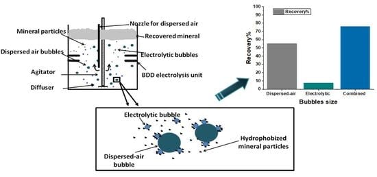
2.3. Experimental Set Up—The Hybrid Flotation Device

The basic laboratory flotation machine used for mineral flotation is a Denver-type commercial mechanical flotation machine (Birminhgam, England). The device is equipped with an acrylic (Plexiglas) flotation tank (V = 3L) and carries an air flowmeter (0–10 L/min), an impeller, and a diffuser. The impeller speed is controlled using a tachometer supported on the device (0–3000 rpm). The device is converted to a hybrid flotation device by placing two boron-doped diamond electrolysis units on the inner walls of the flotation tank (Figure 1b). The first step was the design and manufacture of a bench-scale micro-bubble generator. For this, two single boron-doped diamond (BDD) electrolysis units were manufactured, which serve as micro-bubble generators. BDD electrodes have been chosen due to the advantages and specific properties they provide, such as (i) a large electrochemical potential window, making them stable materials (regarding oxidation or reduction) [66], (ii) stability and resistance to degradation under harsh chemical, mechanical, and thermal conditions [67,68], and (iii) good operation at high current densities, high response reproducibility and long-term response stability, and good biocompatibility [69]. Taking into account all these notable properties BBD electrodes provide, they are considered an excellent choice for water electrolysis and formation of micro-bubbles and moreover for their adaption in a flotation system. The two BDD electrodes, which serve as an anode and a cathode, are supported on a polymeric support (Polyoxymethylene, POM, Figure 1b). The distance between the two electrodes is 2 cm. The electrodes were placed horizontally and parallel and connected to an external power supply. The two electrolysis units were placed 10 cm from the bottom of the tank, in the middle of the inner walls of the tank. The position of the electrodes was selected so that the generated micro-bubbles are dispersed homogeneously in the flotation cell. The resulting flotation device is called the BDD–Hybrid Denver device (BDDHD) (Figure 1b).

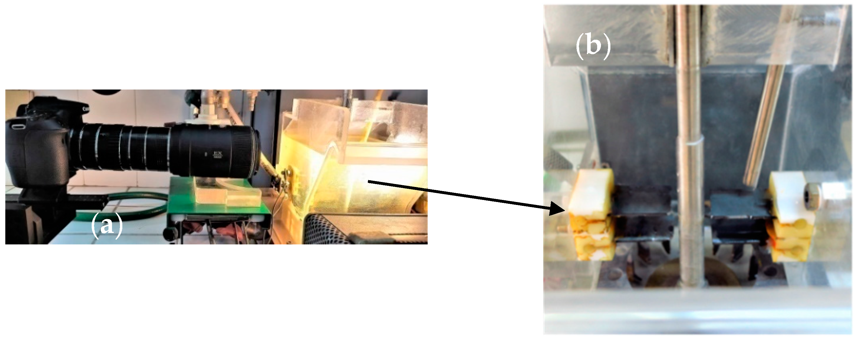
2.4. Bubble Size Measurements

The bubbles of the flotation process were measured by the optical method. Dispersed bubbles correspond to bubbles generated by the Denver flotation device, whereas electrolytic bubbles correspond to those produced by the electrolysis of water. The size of bubbles was determined by capturing bubble images using a high-resolution digital camera (a 20MP Canon EOS 70D, equipped with macro lenses and extension tubes for efficient image magnification) (Figure 1a). The high-definition images captured are imported into an image analysis software (BubbleSEdit software, Laboratory of Chemical and Environmental Technology, Thessaloniki, Greece) [70], which is used to automatically detect the bubbles’ contour and measure their size and consequently obtain the corresponding bubble size distributions. It is worth mentioning that in order to calculate the size of the bubbles from the photos taken, it is necessary to convert the pixels to length (μm). The calibration of the optical measurements is done by capturing a standard 56 μm thick wire with the camera settings used per experimental condition.
Two series of experiments were carried out, each for the corresponding bubble size. The bubble size distributions were determined in the absence of a solid phase (magnesite) and in the presence of a collector (sodium oleate 120 mg/L), frother (pine oil), and electrolyte (NaCl 0.1 M). It is worth mentioning that for each experimental run, more than 500 bubbles were measured in order to be statistically correct.

2.5. Flotation Experiments

For each flotation experiment, 30 g of the mineral was well dispersed in 3 L tap water containing the collector and frother inside the flotation cell. The impeller speed wasset at 1500 rpm, and conditioning took place for 5 min. In the experiments performed in the presence of micro-bubbles, conditioning of fine magnesite particles with micro-bubbles (20 min) was conducted after conditioning with the collector and prior to induction of dispersed (coarse) bubbles. Upon particle conditioning, air (5 L/min) wasintroduced to the flotation cell through a nozzle (nozzle diameter 7 mm). The modified hydrophobic particles collided with the bubbles, and the valuable minerals gathered in the froth layer. At the end of the flotation experiments, the floated/recovered mineral particles were collected, filtered, dried, and weighted.
Froth weight, which contains the recovered mineral particles, is an important indicator of the fine particle flotation enhancement. Calculating the recovered mineral recovery ratio is the experimental validation of the flotation enhancement. At the end of the flotation experiments, the floated mineral particles were collected, dried, and weighed. The recovery of the mineral particles in the froth product (R) was computed as:
R% = 100 C/F
where, C: mass of concentrate, F: mass of feed.
Flotation experiments were performed in triplicate, and the values represent the mean value of independent experiments. The obtained data were presented as average and standard error mean (SEM) values of multiple sets of independent measurements. Recovery percentages and SEMs were calculated for each individual group.
The effect of pH (2–12), collector’s (0–120 mg/L) and electrolyte’s concentration (0–1 M), airflow rate (2–8 L/min), and conditioning time (0–20 min.) with regards to bubble size were investigated. Some of the flotation products were analyzed concerning their particle size distribution in an effort to define the contribution of the electrolytic bubbles to the fine and ultrafine particles’ recovery.

3. Results and Discussion

3.1. Adsorption Results

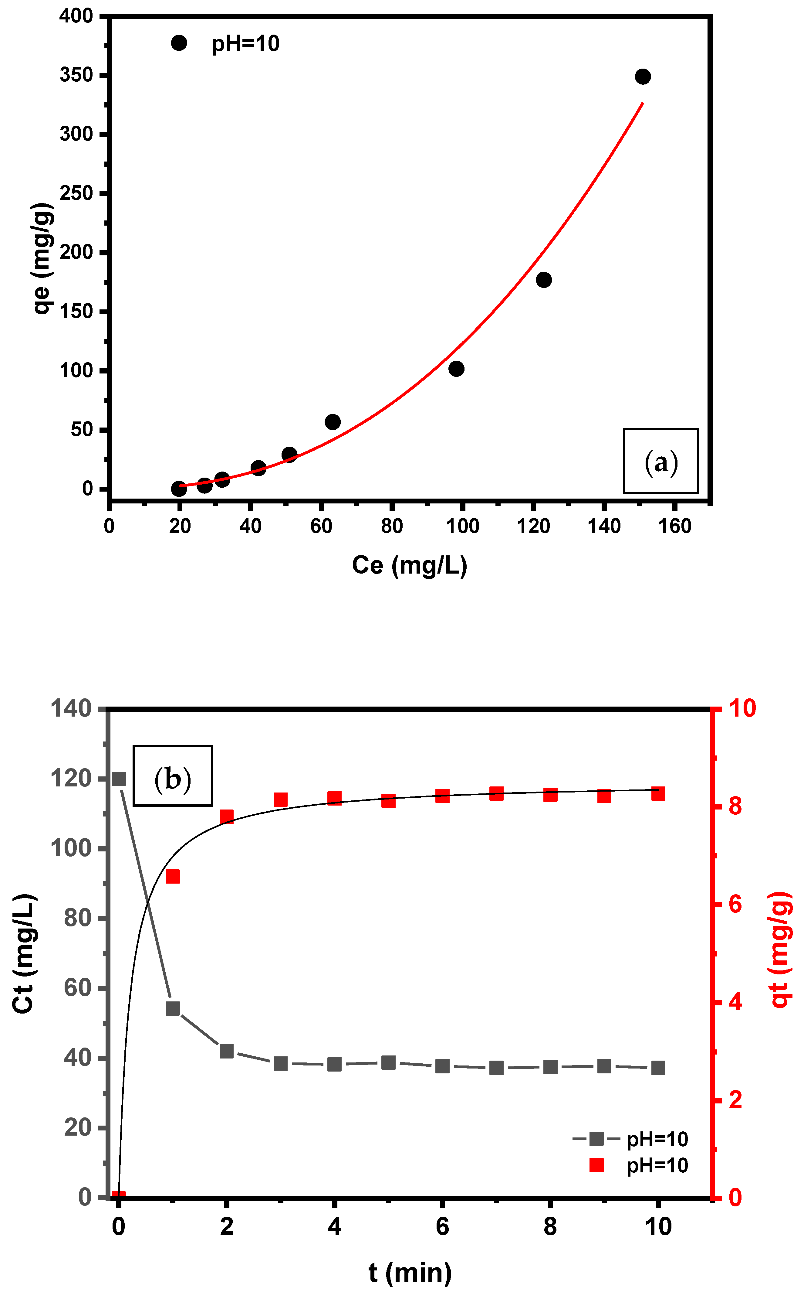
3.1.1. Effect of Initial Sorbate Concentration—Equilibrium Model (Isotherms)

Figure 2a shows the adsorption isotherm of sodium oleate on magnesite at pH value 10. The experimental data (Ce, qe) were fitted to the Freundlich and Langmuir/Freundlich isotherm models, which are the most frequently used [71]. The Freundlich isotherm presumes the surface heterogeneity and defines the exponential distribution of the active sites on the adsorbate surface. The model indicates physisorption on the surface. The Langmuir/Freundlich isotherm model is a combined form of the Langmuir and Freundlich isotherm and describes adsorption on heterogeneous surfaces. With regards to the adsorbate, low or high concentration, the model becomes the Freundlich model or the Langmuir isotherm model, respectively [72]. In Figure 2a, the red line illustrates the adsorption isotherm, whereas the adsorption parameters are collected in Table 3. The Langmuir/Freundlich model fits successfully to the experimental data with the highest value of the correlation coefficients (R2 =0.999), whereas Freundlich’s model fitting was not satisfactory.

3.1.2. Effect of Contact Time—Kinetic Models

Kinetic adsorption experiments were conducted in order to determine the essential time for the adsorption of the collector on the mineral’s surface to reach equilibrium. Figure 2b illustrates the effect of contact time on residual concentration Ct of sodium oleate and the adsorption capacity qt of magnesite at optimum pH = 10 [16,73]. Figure 2b shows that the initial sodium oleate concentration 120 mg/L is reduced to 55 and 40 mg/L after one and three minutes of mixing, respectively. Equilibrium was reached within three minutes, and the sorption capacity was approximately 8 mg/g. The data of sorption loading, qt, were fitted to the two kinetic models, and the kinetic parameters are presented in Table 4. Based on the correlation coefficients (R2), the best fitting was obtained for the pseudo-second-order equation (R2 > 0.999), while the pseudo-first-order model presented lower coefficients. This means that adsorption takes place possibly through chemisorption. The (solid) continuous curve represents the pseudo-second-order kinetic model. From the results obtained, it is concluded that conditioning of magnesite with sodium oleate in order to render magnesite hydrophobic can be completed satisfactorily after 3 min.

3.1.3. Adsorption Mechanism

The collector adsorption on the surface of minerals as a function of pH has been studied in various research works [54,74]. Rao et al. extensively studied the mechanism of oleate on salt-type minerals and more specifically on calcite (CaCO3) [73]. Given that calcium and magnesium have the same outer electron structure, since they are both located on the second column of the periodic table (alkaline earth metal group), they have similar chemical properties and behavior. Cases et al. [75] considered that adsorption of surfactants with more than eight methylene groups in their structure interact two-dimensionally with the surface of the mineral. Moreover, results from various experimental data depict that the basic interaction between oleate and calcium surface is chemisorption. Precipitated sodium calcium forms, whichis later adsorbed on the chemisorbed oleate layer [76,77]. Based on these observations, it is assumed that the same mechanism is followed by sodium oleate adsorption on magnesite. Additionally, the suggested mechanism (chemisorption) is in line with the present experimental results (pseudo-second-order kinetic model).

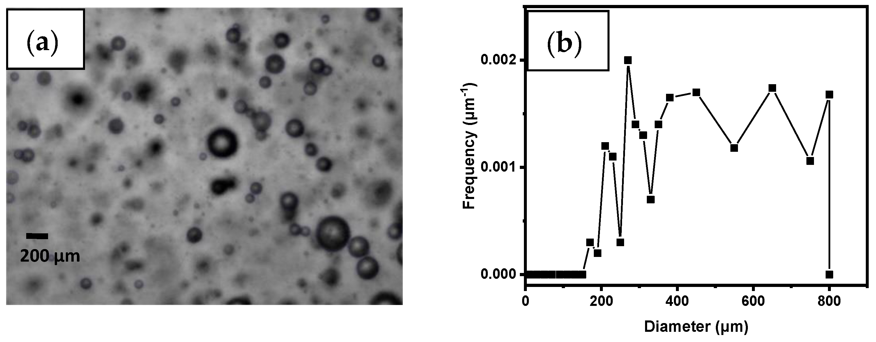
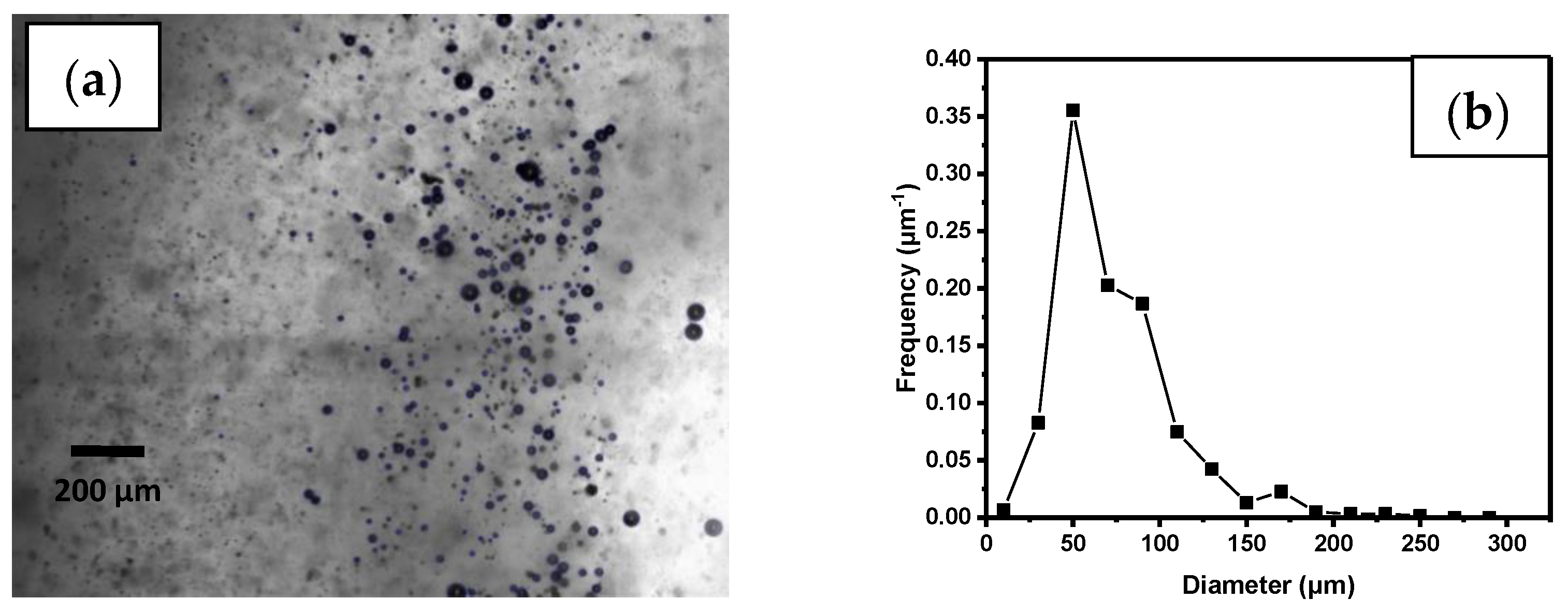
3.2. Bubble Size Measurements

Figure 3 shows the mean bubble size of dispersed bubbles generated in the hybrid Denver in presence of the flotation reagents, which is 0.6 mm (0.17–0.8 mm). The usual bubble size of dispersed-air bubbles in a mechanical Denver device is 0.5–2 mm [78]. The presence of a strong anionic collector such as sodium oleate and electrolyte at the optimum flotation conditions (120 mg/L and 0.1 M respectively) decreases the bubble size to the computed one.
The mean size of the electrolytic bubbles in the hybrid cell is illustrated in Figure 4. The bubble size distribution graph shows that mean bubble size is 76 μm (10–250 μm). Typical electroflotation devices (usually flotation columns) generate bubbles with mean size <100 μm [79]. Xu et al. studied the effects of an anionic surfactant and electrolyte on bubble size and proposed that electrostatic repulsion between the anionic surfactant molecules is reduced due to the fact that the electrolyte’s counter-ions attach to the anionic surfactant’s head groups. This results in a much closer formed monolayer film at the interface; thus, smaller and more stable bubbles are formed [80].

3.3. Flotation Results

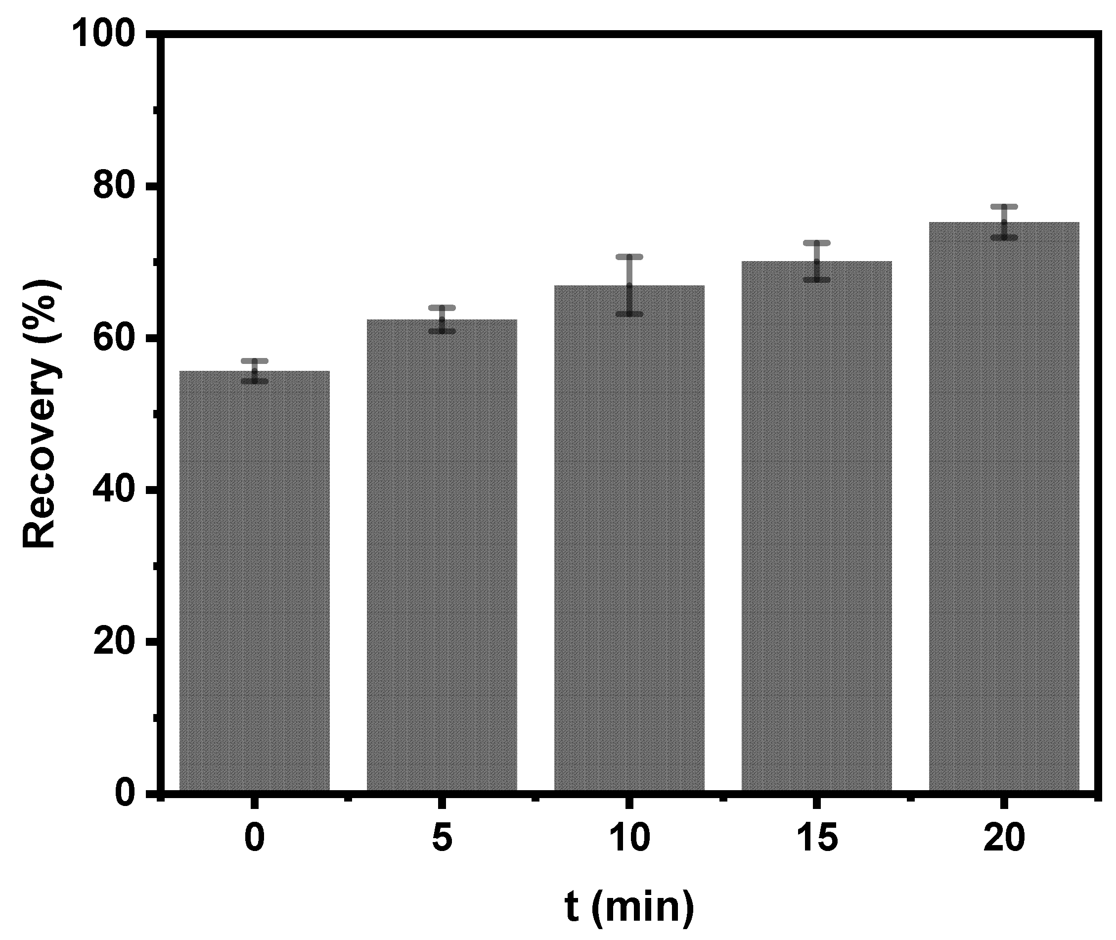
3.3.1. Effect of Conditioning Time with Electrolytic Bubbles

Figure 5 illustrates the effect of the treating time of the hydrophobized mineral with electrolytic micro-bubbles prior to inserting dispersed bubbles into the flotation cell. The results clearly depict that conditioning magnesite with electrolytic bubbles enhances flotation recovery, and the maximum recovery is achieved when treatment time reached 20 min. In particular, fine mineral particle recovery in the absence of electrolytic bubbles was 55% and when treating magnesite with the micro-bubbles for 20 min recovery reached 75%. The results show the strong impact of the presence of electrolytic bubbles on fine particle recovery. This is attributed to the formation of hetero-aggregates (of particles and bubbles) due to electrostatic attraction between particles and micro-bubbles. It is assumed that flotation effectiveness is achieved due to the fact that electrolytic bubbles act as selective flocculants, promoting the formation of large aggregates, which are easier to float by dispersed-air bubbles [81].

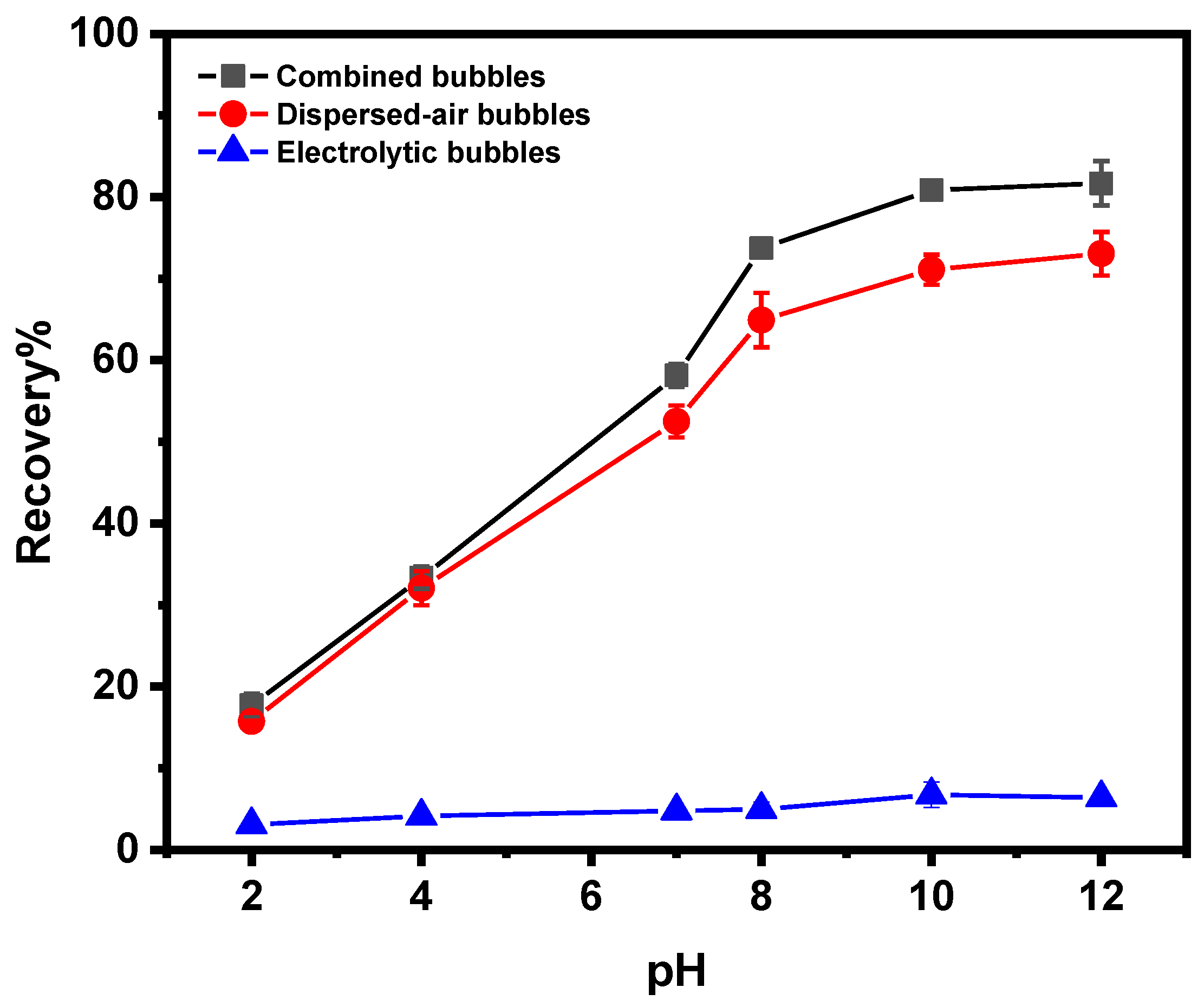
3.3.2. Effect of pH on Magnesite Flotation

Figure 6 shows the effect of pH on the flotation recovery of magnesite, as well as the dependence of recovery on the size of the bubbles, in the presence of sodium oleate as the collector. The pH values were varied in the range 2–12. The graph shows that recovery of magnesite is very poor in acidic conditions. Flotation recovery of magnesite increases with the increase of the pulp pH value. At pH 7–10, the recovery of magnesite increased from 52.5% to 71.1% and from 58.2% to 80.9% in the absence and presence of electrolytic bubbles, respectively. The floatability of magnesite increases notably as the pH value increases, reaching the maximum recovery value at pH 10. The results are in good agreement with a previous study related to magnesite flotation [82]. Magnesite as a salt-type mineral depicts solubility, and its dissolved species (Mg ions) take part in reactions such as hydrolysis and adsorption, and as a result, these reactions affect the interactions with the collector [82]. The solubility of magnesite in acidic pH values is rather high [63]. Yang et al. [83] measured the zeta potential of magnesite as a function of pH. In the whole pH range, magnesite’s potential has negative values, and moreover, at pH 10 shifts to an even lower value, indicating the strong adsorption of sodium oleate occurring on magnesite. At pH values lower than 6, the magnesite surface is positively charged, and the adsorption of anions would be expected [63]. However, the effect of the surface charge is not significant in the anionic magnesite flotation, and as is indicated in Figure 6, the adsorption of sodium oleate (anionic collector) does not occur effectively, so flotation is not promoted at pH values lower than 6. This is probably due to the fact that adsorption of the collector on magnesite surface occurs possibly by chemisorption [84]. Based on the aforementioned observations, the pH value of 10 was selected for conducting the flotation experiments.
Moreover, Figure 6 indicates that the higher flotation efficiency for fine magnesite particles was achieved in the presence of electrolytic bubbles. The results show that the presence of micro-bubbles has an impact on the recovery of fine magnesite particles, leading to a 10% recovery improvement. Single electrolytic bubbles are not able to float magnesite particles. Based on the literature review, it is assumed that electrolytic bubbles act on increasing the apparent size of fine particles and hence enhancing their floatability [85]. Rulyov et al. [48] introduced the hetero-aggregation of fine particles with micro-bubbles in a non-uniform hydrodynamic field in a flotation cell. More specifically, micro-bubbles act as carriers. As a result, the capture efficiency of the formed particle-micro-bubble hetero-aggregates exceeds the capture efficiency of particles by conventional-sized bubbles. Moreover, the flotation rate of the formed hetero-aggregates by coarse bubbles is much higher than that of separate particles.

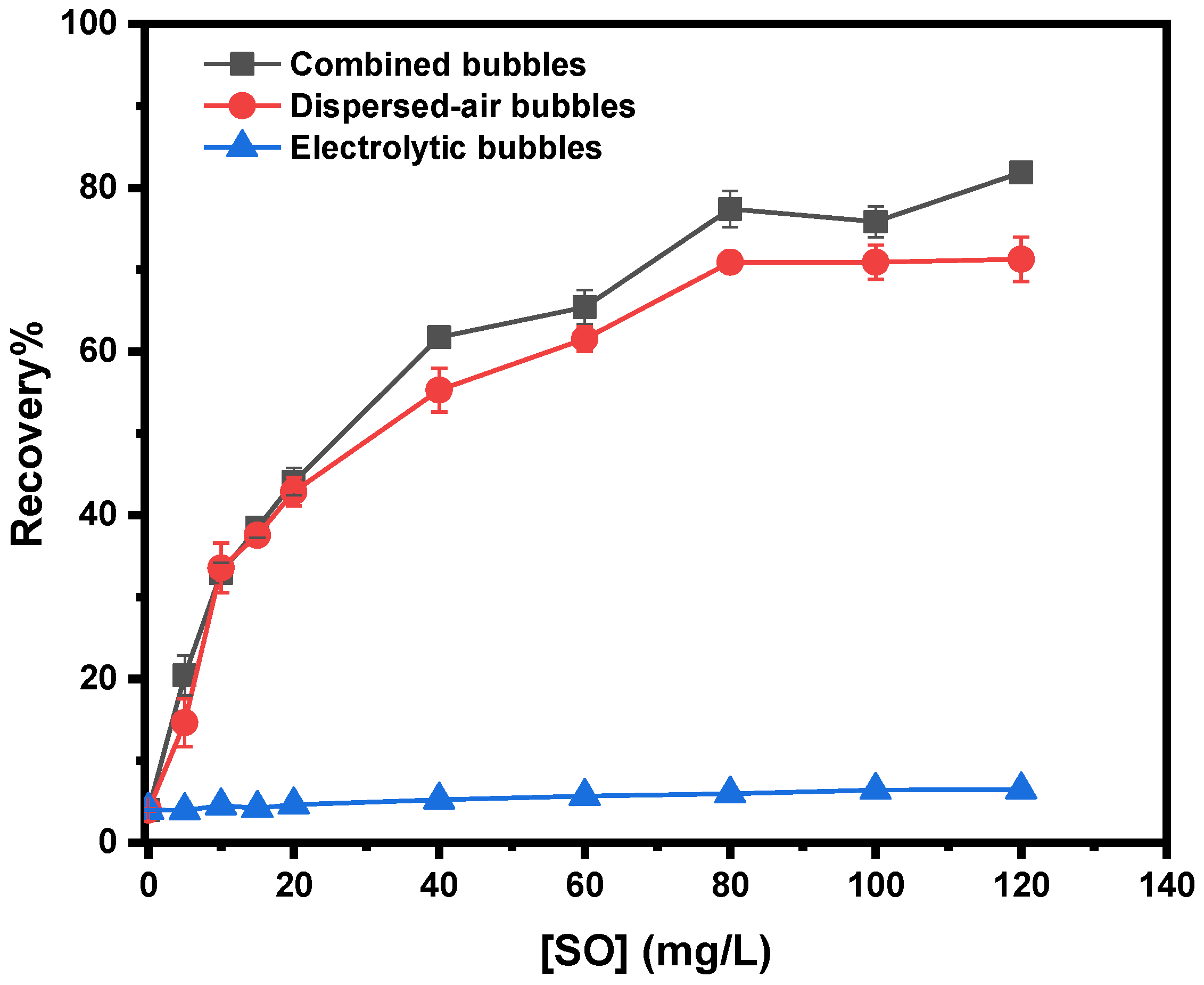
3.3.3. Effect of Collector’s Concentration

Figure 7 shows the dependence of magnesite flotation recovery by the collector’s concentration in the presence and absence of electrolytic bubbles at pH = 10. Previous wetting studies of the surface of magnesite showed that as a nonmetallic, hydrophilic mineral, it has a small contact angle in water (10.4°). After conditioning with the anionic collector sodium oleate at pH 10.2, the value of the contact angle increases to 79°, thus increasing its hydrophobicity [54,63,86]. As sodium oleate’s concentration increases, the recovery of magnesite raises. The recovery exceeded 83% when the dosage of the collector was 120 mg/L. Increasing sodium oleate’s dosage, magnesite’s recovery was stable; therefore, the dosage of the collector 120 mg/L can be set as the best flotation collector dosage. In addition, Figure 7 shows that recovery of fine magnesite particles can be enhanced by the presence of micro-bubbles raising minerals recovery from 71.3% to 81.9%.

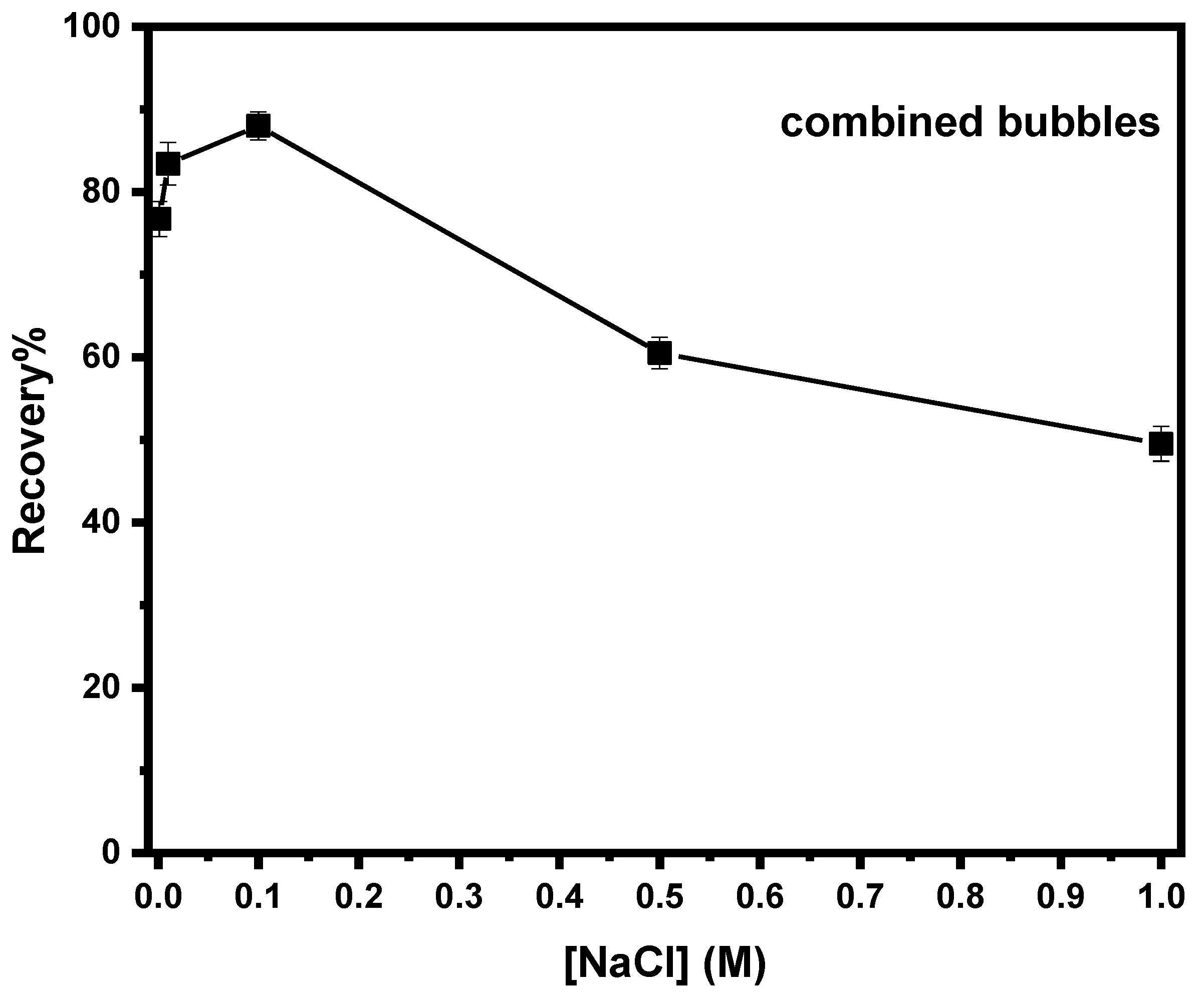
3.3.4. Effect of Electrolyte’s Concentration on Combined Flotation of Magnesite

Electrolyte plays an important role during water electrolysis, increasing the conductivity in the solution and furthermore the efficiency of the process. More specifically, an inorganic electrolyte reduces the surface hydration of mineral particles, thus increasing their attachment to the bubbles [87]. Moreover, Marrucci et al. proposed that the presence of an inorganic electrolyte leads to a decrease of bubbles’ coalescence (formation of fine bubbles) and the formation of a stable froth zone [88]. The electrolyte used in the current study was sodium chloride (NaCl,) and pH = 10, sodium oleate = 120 mg/L, and current density = 0.1 A were kept constant throughout the experiments. The results (Figure 8) depict that the addition of the electrolyte initially enhances the flotation recovery assisted by electrolytic bubbles, but when NaCl concentration exceeded 0.1 M, recovery decreased.
Moreover, the addition of an electrolyte in a solution leads to an increase in bubbles’ surface potential, which means repulsive forces between bubbles and particles are promoted [89]. It is also worth mentioning that, in cases of excess concentration of inorganic salts in flotation, pulp might have a depressing effect on the flotation of some particles [32]. However, high electrolyte concentration creates higher electrical conductivity, which results in lower voltage under the same current density leading to lower power consumption [90].

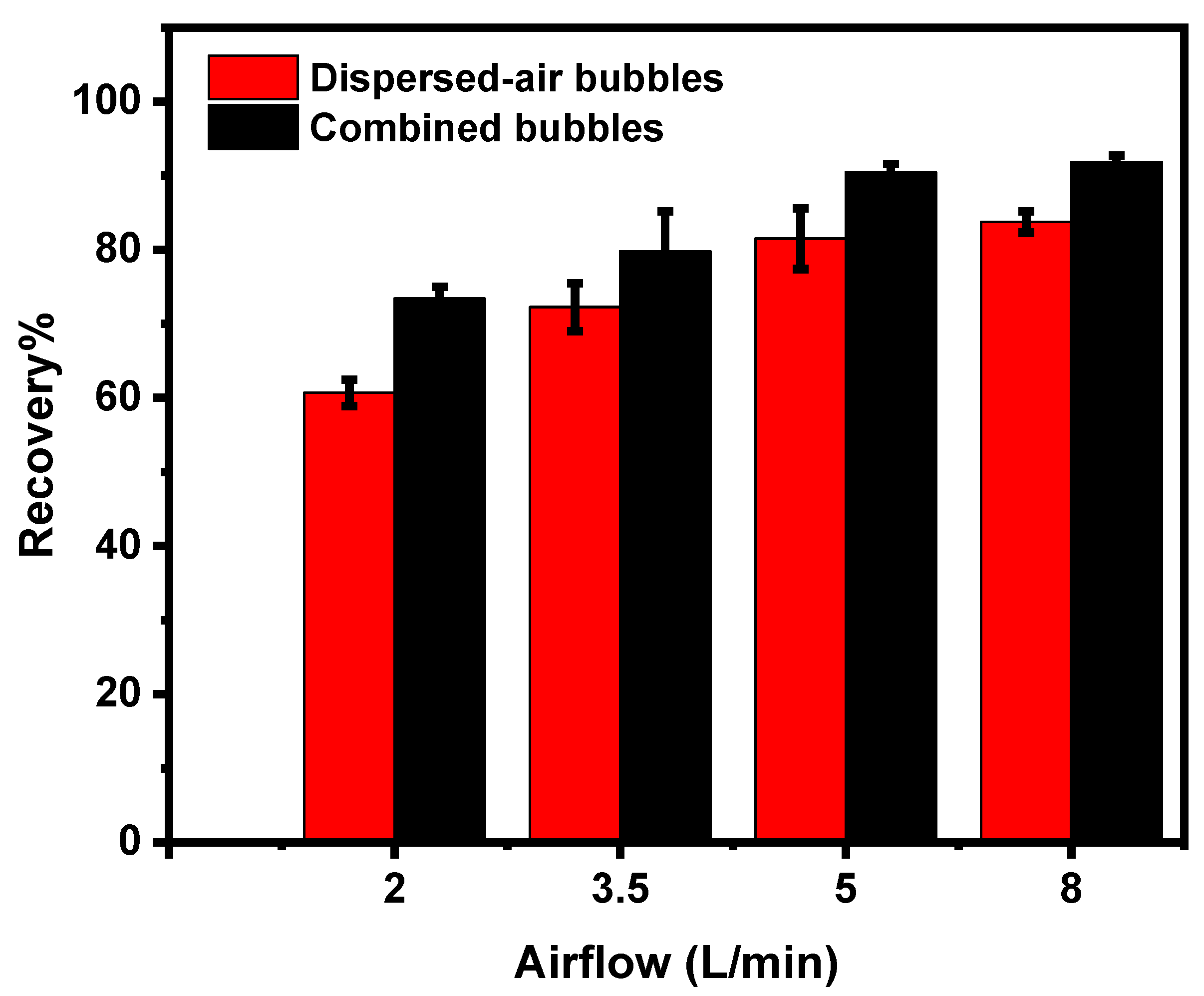
3.3.5. Effect of Airflow Rate on Magnesite Flotation

Mechanical flotation performance is undoubtedly affected both by the airflow rate and the impeller speed. Airflow rate plays an important role regarding the flotation kinetics. The effect of the airflow rate is a topic investigated by several researchers [91,92,93,94]. The effect of the variable air flow rate on fine magnesite recovery is shown in Figure 9 in the presence and in absence of electrolytic bubbles. Recovery is decreased at low airflow rates, whereas it increases as aeration rate increases to reach a maximum at 5 L/min, both in the presence and absence of electrolytic bubbles. The experimental results indicate that at higher airflow rates (8 L/min), the recovery of fine particles was stable. Abdo et al. suggested that low airflow rates lead to lower recoveries due to the fact that the flow rate of water to the froth is decreased [95]. Moreover, low aeration rates can cause froth overloading, resulting in the drainage of particles located inthe froth back to the pulp. It should be also noted that high aeration rates can cause high turbulent conditions and deposition of particles in the flotation cell, thus lowering their recovery [95].

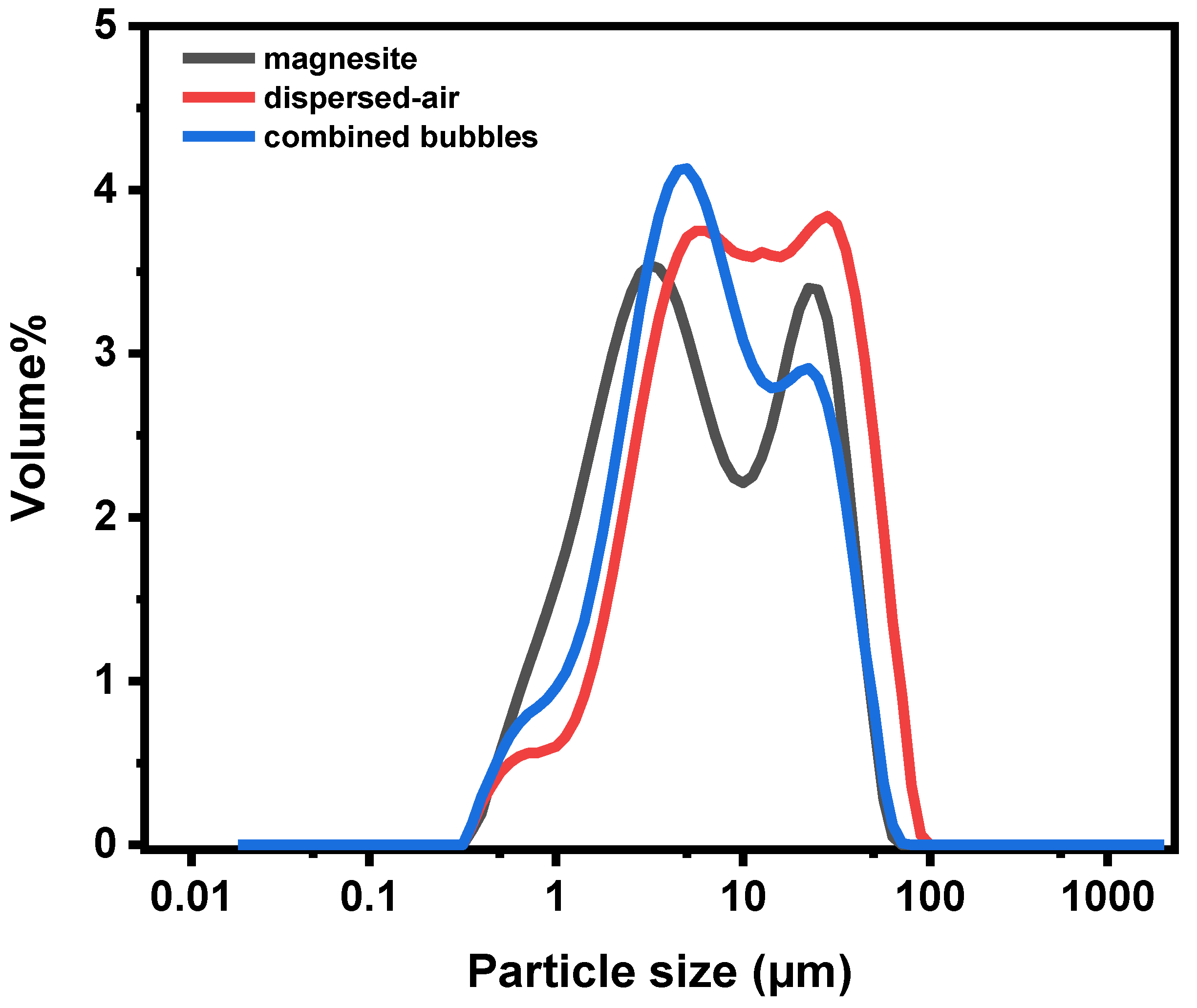
3.3.6. Particle Size Distribution after Flotation

Upon the complementation of the flotation experiments, the particle size analysis of the froth products was conducted. The analysis was realized under the framework of defining the particle size range of the mineral particles that floated with the experimental conditions studied. The analysis was conducted on flotation products recovered in the presence and absence of electrolytic bubbles in order to ascertain the contribution of micro-bubbles on fine magnesite flotation and moreover to define which particle fraction influences the most. Figure 10 depicts the particle size distribution of raw magnesite, magnesite that floated by employing only dispersed-air bubbles, and magnesite recovered by combining electrolytic and dispersed-air bubbles. When employing only dispersed-air bubbles, the froth product contained magnesite particles with size 20–35 μm. Moreover, the analysis shows that when applying conditioning of fine magnesite particles with electrolytic bubbles, recovery of finer mineral particles occurs (3–10 μm). The particle size analysis of the recovered mineral is an important indicator depicting that combining micro-bubbles with dispersed-air bubbles leads to more effective flotation performance of fine and ultrafine mineral particles.

4. Conclusions

In the present research, the design and construction of a hybrid mechanical flotation device capable of producing bubbles of different size by combining conventional-sized bubbles (dispersed air) and micro-bubbles (electrolysis of water) is proposed. The gas phase of the new device is characterized by optical measurements, and bubble size distributions were extracted for both dispersed and electrolytic bubbles. The mean bubble diameter was estimated to be 611 and 76 μm, respectively.
Adsorption experiments were performed in the framework of describing the adsorption of the collector upon the mineral. The experimental results indicate that adsorption of sodium oleate is effective at pH 10, which is in good agreement with the optimum pH value in the flotation process. Chemisorption of sodium oleate is more effective inbasic conditions, rendering the mineral hydrophobic and thus promoting its floatability. The kinetic results indicate that adsorption is completed in 3 min and that indicates the effective time of conditioning the mineral with the collector.
During flotation experiments, the effect of conditioning time with electrolytic bubbles, pH, collector’s and electrolyte’s concentration, and airflow rate with regards to bubble size were examined. The fact that all curves of combined bubbles are always above the curves employing dispersed-air bubbles indicates that the presence of electrolytic bubbles enhances the flotation recovery of fine magnesite particles by approximately 10%. Particle size analysis of the froth product showed that the presence of electrolytic bubbles enhances the flotation recovery of finer particles more than when employing only dispersed-air bubbles. Fine magnesite particles assisted by electrolytic bubbles appear to be a result of the following phenomena:
  • Adsorption of oleate’s molecules onto magnesite particles with the polar part on the surface of the mineral renders magnesite particles hydrophobic.
  • Aggregation (or more specific hetero-aggregation) of fine particles with electrolytic bubbles.
  • Attachment of the formed aggregates with the dispersed-air bubbles.
The results obtained from the particle size analysis of the froth product in the presence and absence of electrolytic bubbles is evidence indicating the auxiliary role of the micro-bubbles. The employment of other analytical techniques (e.g., FBRM) would more thoroughly support the results to validate that fine mineral particle flotation is assisted by the presence of electrolytic bubbles.
As a future challenge, it is believed that employing electrolysis for micro-bubble generation in support of fine particle flotation enhancement will be used economically on anindustrial scale. Therefore, research must continue on alarger scale.

Author Contributions

Conceptualization, M.K., T.D.K. and N.K.L.; Data curation, P.K.T.; Investigation, P.K.T.; Supervision, M.K., T.D.K. and N.K.L.; Writing—original draft, P.K.T.; Writing—review & editing, M.K., T.D.K. and N.K.L. All authors have read and agreed to the published version of the manuscript.

Funding

The present research was funded by the European Union’s Horizon 2020 research and innovation program under grant agreement No. 821265—FineFuture.

Data Availability Statement

The data presented in this study are available upon request from the corresponding author.

Acknowledgments

The authors would like to acknowledge Grecian Magnesite for providing magnesite samples for this study.

Conflicts of Interest

The authors declare that they have no known competing financial interests or personal relationships that could have appeared to influence the work reported in this paper.

References

  1. Glembotskii, V.A.; Klassen, V.I.; Plaksin, I.N. Flotation; Primary Sources: New York, NY, USA, 1972; p. 633. [Google Scholar]
  2. Grotowski, A.; Witecki, K. Research on the Possibility of Sorting Application for Separation of Shale and/or Gangue from the Feed of Rudna Concentrator; KGHM Cuprum Ltd.; Research and Development Center; Mineral Engineering Conference; MEC2017; EDP Sciences: Wrocław, Poland, 2017. [Google Scholar] [CrossRef] [Green Version]
  3. Soto, H.; Barbery, G. Separation of fine particles by floc flotation. Production and Processing of Fine Particles. In Proceedings of the International Symposium on the Production and Processing of Fine Particles, Montreal, QC, Canada, 28–31 August 1988. [Google Scholar] [CrossRef]
  4. Subrahmanyam, T.V.; Forssberg, K.S.E. Mineral solution-interface chemistry in minerals engineering. Miner. Eng. 1993, 6, 439–454. [Google Scholar] [CrossRef]
  5. Lange, A.G.; Skinner, W.M.; Smart, R.S.C. Fine: Coarse particle interactions and aggregation in sphalerite flotation. Miner. Eng. 1997, 10, 681–693. [Google Scholar] [CrossRef]
  6. Feng, D.; Aldrich, C. Effect of particle size on flotation performance of complex sulphide ores. Miner. Eng. 1999, 12, 721–731. [Google Scholar] [CrossRef]
  7. Song, S.; Lopez-Valdivieso, A.; Reyes-Bahena, J.L.; Lara-Valenzuela, C. Floc flotation of galena and sphalerite fines. Miner. Eng. 2001, 14, 87–98. [Google Scholar] [CrossRef]
  8. Liu, J.; Mak, T.; Zhou, Z.; Xu, Z. Fundamental study of reactive oily- bubble flotation. Miner. Eng. 2002, 15, 667–676. [Google Scholar] [CrossRef]
  9. Pyke, B.; Fomaserio, D.; Ralston, J. Bubble particle heterocoagulation under turbulent conditions. J. Colloid Interface Sci. 2003, 265, 141–151. [Google Scholar] [CrossRef]
  10. Leistner, T.; Embrechts, M.; Leißner, T.; Chehreh Chelgani, S.; Osbahr, I.; Möckel, R.; Peuker, U.A.; Rudolph, M. A study of the reprocessing of fine and ultrafine cassiterite from gravity tailing residues by using various flotation techniques. Miner. Eng. 2016, 96–97, 94–98. [Google Scholar] [CrossRef]
  11. Gorman, M.G.; Smith, R.W. Amine flotation of fine quartz and glass beads. Miner. Eng. 1991, 4, 1219–1226. [Google Scholar] [CrossRef]
  12. Yoon, R.H.; Luttrell, G.H. The effect of bubble size on fine coal flotation. Coal Prep. 1986, 2, 179–192. [Google Scholar] [CrossRef]
  13. Yoon, R.H.; Luttrell, G.H. The effect of bubble size on fine particle flotation. Miner. Process. Extr. Metall. Rev. 1989, 5, 101–122. [Google Scholar] [CrossRef]
  14. Yoon, R.H. Microbubble flotation. Miner. Eng. 1993, 6, 619–630. [Google Scholar] [CrossRef]
  15. Hewitt, D.; Fornasiero, D.; Ralston, J. Bubble-Particle Attachment. Chem. Soc. Faraday Trans. 1995, 91, 1997–2001. [Google Scholar] [CrossRef]
  16. Matis, K.A.; Gallios, G.P.; Kydros, K.A. Separation of fines by flotation techniques. Sep. Technol. 1993, 3, 76–90. [Google Scholar] [CrossRef]
  17. Koh, P.T.L.; Schwarz, M.P. CFD modelling of bubble-particle collision rates and efficiencies in a flotation cell. Miner. Eng. 2003, 16, 1055–1059. [Google Scholar] [CrossRef]
  18. Mimezami, M.; Hashemi, M.S.; Finch, J.A. Effect of sulphates on aggregation of alumina and pyrite. In Particle Size Enlargement in Mineral Processing, Proceedings of the 5th UBC-McGill International Symposium, Hamilton, ON, Canada, 26 August 2004; Laskowski, J.S., Ed.; Canadian Institute of Mining, Metallurgy and Petroleum: Westmount, QC, Canada, 2004; pp. 159–168. [Google Scholar]
  19. Zhang, X.; Hu, Y.; Sun, W.; Xu, L. The effect of polystyrene on the carrier flotation of fine smithsonite. Minerals 2017, 7, 52. [Google Scholar] [CrossRef] [Green Version]
  20. Ahmed, N.; Jameson, G.J. The effect ofbubble size on the rate of flotation of fine particles. Int. J. Miner. Process. 1985, 14, 195–215. [Google Scholar] [CrossRef]
  21. Dai, Z.; Fornasiero, D.; Ralston, J. Particle-bubble collision models—A review. Adv. Colloid Interfac. 2000, 85, 231–256. [Google Scholar] [CrossRef]
  22. Tao, D. Role of Bubble Size in Flotation of Coarse and Fine Particles—A Review. Separ. Sci. Tech. 2005, 39, 741–760. [Google Scholar] [CrossRef]
  23. Dai, Z.; Dukhin, S.S.; Fornasiero, D.; Ralston, J. The inertial hydrodynamic interaction of particles and rising bubbles with mobile surfaces. J. Colloid Interface Sci. 1998, 197, 275–292. [Google Scholar] [CrossRef]
  24. Dai, Z.; Fornasiero, D.; Ralston, J. Particle–bubble attachment in mineral flotation. J. Colloid Interface Sci. 1999, 217, 70–76. [Google Scholar] [CrossRef]
  25. Bennett, A.J.R.; Chapman, W.R.; Dell, C.C. Studies in froth flotation of coal. In Third International Coal Preparation Conference, Liege, 1958; Editions techniques et scientifiques; Borreng: Bruxelles, Belgium, 1958; pp. 37–39 rue. [Google Scholar]
  26. Reay, D.; Ratcliff, G.A. Experimental testing of the hydrodynamic collision model of fine particle flotation. Can. J. Chem. Eng. 1975, 53, 481–486. [Google Scholar] [CrossRef]
  27. Miettinen, T.; Ralston, J.; Fornasiero, D. The limits of fine particle flotation. Miner. Eng. 2010, 23, 420–437. [Google Scholar] [CrossRef]
  28. Venkatachalam, S. Electrogenerated Gas Bubbles in Flotation. Miner. Process. Extr. Metall. Rev. 1992, 8, 47–55. [Google Scholar] [CrossRef]
  29. Llerena, C.; Ho, J.C.K.; Piron, D.L. Effects of pH on electroflotation of sphalerite. Chem. Eng. Commun. 1996, 155, 217–228. [Google Scholar] [CrossRef]
  30. Kydros, K.A.; Gallios, G.P.; Matis, K.A. Electrolytic flotation of pyrite. J. Chem. Technol. Biotechnol. 1994, 59, 223–232. [Google Scholar] [CrossRef]
  31. Tadesse, B.; Albijanic, B.; Makuei, F.; Browner, R. Recovery of fine and ultrafine mineral particles by electroflotation—A review. Miner. Process. Extr. Metall. Rev. 2018, 1–15. [Google Scholar] [CrossRef]
  32. Montes-Atenas, G.; Garcia-Garcia, F.J.; Mermillod-Blondin, R.; Montes, S. Effect of suspension chemistry onto voltage drop: Application of electro-flotation. Powder Technol. 2010, 204, 1–10. [Google Scholar] [CrossRef]
  33. Fan, M.; Tao, D.; Honaker, R.; Luo, Z.F. Nanobubble generation and its application in froth flotation (part I): Nanobubble generation and its effects on the properties of microbubble and millimeter scale bubble solutions. Min. Sci. Technol. 2010, 20, 1–19. [Google Scholar] [CrossRef]
  34. Fan, M.; Tao, D.; Honaker, R.; Luo, Z.F. Nanobubble generation and its application in froth flotation (part II): Fundamental study and theoretical analysis. Min. Sci. Technol. 2010, 20, 159–177. [Google Scholar] [CrossRef]
  35. Calgaroto, S.; Azevedo, A.; Rubio, J. Flotation of quartz particles assisted by nanobubbles. Int. J. Miner. Process. 2015, 137, 64–70. [Google Scholar] [CrossRef]
  36. Tussupbayev, N.K.; Rulyov, N.N.; Kravtchenco, O.V. Microbubble augmented flotation of ultrafine chalcopyrite from quartz mixtures. Miner. Process. Extr. Metall. Rev. 2016, 125, 5–9. [Google Scholar] [CrossRef]
  37. Filippov, L.O.; Severov, V.V.; Filippova, I.V. An overview of the beneficiation of iron ores via reverse cationic flotation. Int. J. Miner. Process. 2014, 127, 62–69. [Google Scholar] [CrossRef]
  38. Jameson, G.J. New directions in flotation machine design. Miner. Eng. 2010, 23, 835–841. [Google Scholar] [CrossRef]
  39. Mankosa, M.J.; Kohmuench, J.N.; Christodoulou, L.; Yan, E.S. Improving fine particle flotation using the StackCell™ (raising the tail of the elephant curve). Miner. Eng. 2018, 121, 83–89. [Google Scholar] [CrossRef]
  40. Xiong, Y.; Peng, F. Optimization of cavitation venturi tube design for pico and nano bubbles generation. Int. J. Min. Sci. Technol. 2015, 25, 523–529. [Google Scholar] [CrossRef]
  41. Kohmuench, J.N.; Luttrell, G.; Mankosa, M. Coarse particle concentration using the HydroFloat separator. Miner. Metall. Process. 2001, 18, 61–67. [Google Scholar] [CrossRef]
  42. Clayton, R.; Jameson, G.J.; Manlapig, E.V. The development and application of the Jameson cell. Miner. Eng. 1991, 4, 925–933. [Google Scholar] [CrossRef]
  43. Honaker, R.Q.; Mohanty, M.K. Enhanced column flotation performance for fine coal cleaning. Miner. Eng. 1996, 9, 931–945. [Google Scholar] [CrossRef]
  44. Yoon, R.H.; Luttrell, G.H. Microcel column flotation scale-up and plant practice. In Proceedings of the 26th Annual Meeting Canadian Mineral Processing, CIM, Ottawa, ON, Canada, 18–20 January 1994; Volume 12. [Google Scholar]
  45. Jameson, G.J.; Nguyen, A.V.; Ata, S. The flotation of fine and coarse particles. In Froth Flotation: A Century of Innovation; Fuerstenau, M.C., Jameson, G.J., Yoon, R.H., Eds.; Society for Mining, Metallurgy & Exploration: Littleton, CO, USA, 2007; pp. 339–372. [Google Scholar]
  46. Prakash, R.; Majumder, S.K.; Singh, A. Flotation technique: Its mechanisms and design parameters. Chem. Eng. Process. 2018, 127, 249–270. [Google Scholar] [CrossRef]
  47. Rulyov, N.N.; Filippov, L.O.; Kravchenko, O.V. Combined Microflotation of Glass Beads. Colloid Surf. A Physicochem. Eng. Asp. 2020, 598, 124810. [Google Scholar] [CrossRef]
  48. Rulyov, N.N. Combined microflotation of fine minerals: Theory and experiment. Miner. Process. Extr. Metall. Rev. 2016, 125, 81–85. [Google Scholar] [CrossRef]
  49. Hassanzadeh, A.; Sajjady, S.A.; Gholami, H.; Amini, S.; Özkan, S.G. An Improvement on Selective Separation by Applying Ultrasound to Rougher and Re-Cleaner Stages of Copper Flotation. Minerals 2020, 10, 619. [Google Scholar] [CrossRef]
  50. Filippov, L.O.; Matinin, A.S.; Samiguin, V.D.; Filippova, I.V. Effect of ultrasound on flotation kinetics in the reactor-separator. J. Phys. Conf. Ser. 2013, 416, 1–6. [Google Scholar] [CrossRef]
  51. Aslani, S.; Samim, B.; Hashemi, H.R.; Arianpour, F. Beneficiation of Iranian magnesite ores by reverse flotation process and its effects on shaped and unshaped refractories properties. Bull. Mater. Sci. 2010, 33, 697–705. [Google Scholar] [CrossRef]
  52. Amer, A.M.; Staden, V. Hydrometallurgical processing of low grade Egyptian magnesite. Physicochem. Probl. Miner. Process. 2010, 44, 5–12. [Google Scholar]
  53. Erdoğan, N. The Most Suitable Beneficiation Method for Magnesite Ore. In Proceedings of the 15thInternational Mineral Processing Symposium, Istanbul, Turkey, 19–21 October 2016. [Google Scholar]
  54. Gence, N.; Ozbay, N. pH dependence of electrokinetic behavior of dolomite and magnesite in aqueous electrolyte solutions. Appl. Surf. Sci. 2006, 252, 8057–8061. [Google Scholar] [CrossRef]
  55. Moudgil, B.M.; Ince, D.E. Flotation Separation of Apatite from Dolomite Using Dodecylamineand Sodium Chloride. In Particle Technology and Surface Phenomena in Minerals and Petroleum; Springer: Boston, MA, USA, 1991; pp. 191–197. [Google Scholar]
  56. Matis, K.A.; Balabanidis, T.H.N.; Gallios, G.P. Processing of Magnesium Carbonate Fines by Dissolved-Air Flotation. Colloids Surf. 1988, 29, 191–203. [Google Scholar] [CrossRef]
  57. Ni, X.; Liu, Q. Adsorption behaviour of Sodium Hexametaphosphate on Pyrochlore and Calcite. Can. Metall. Q. 2013, 52, 473–478. [Google Scholar] [CrossRef]
  58. Luo, X.; Wang, Y.; Wen, S.; Ma, M.; Sun, C.; Yin, W.; Ma, Y. Effect of carbonate minerals on quartz flotation behavior under conditions of reverse anionic flotation of iron ores. Int. J. Miner. Process. 2016, 152, 1–6. [Google Scholar] [CrossRef]
  59. Mishchuk, N.; Ralston, J.; Fornasiero, D. Influence of dissolved gas on van der Waals forces between bubbles and particles. J. Phys. Chem. A. 2002, 106, 689–696. [Google Scholar] [CrossRef]
  60. Mishchuk, N.; Ralston, J.; Fornasiero, D. Influence of very small bubbles on particle/bubble heterocoagulation. J. Colloid Interface Sci. 2006, 301, 168–177. [Google Scholar] [CrossRef]
  61. Zhou, Z.A.; Xu, Z.; Finch, J.A.; Hu, H.; Rao, S.R. Role of hydrodynamic cavitation in fine particle flotation. Int. J. Miner. Process. 1997, 51, 139–149. [Google Scholar] [CrossRef]
  62. Cho, Y.S.; Laskowski, J.S. Bubble coalescence and its effect on dynamic foam stability. Can. J. Chem. Eng. 2002, 80, 299–305. [Google Scholar] [CrossRef]
  63. Gence, N. Wetting behavior of magnesite and dolomite surfaces. Appl. Surf. Sci. 2006, 252, 3744–3750. [Google Scholar] [CrossRef]
  64. Yin, W.; Sun, Q.; Li, D.; Tang, Y.; Fu, Y.; Yao, J. Mechanism and application on sulphidizing flotation of copper oxide with combined collectors. Trans. Nonferrous Met. Soc. China 2019, 29, 178–185. [Google Scholar] [CrossRef]
  65. Fu, Y.; Yin, W.; Yang, B.; Li, C.; Zhu, Z.; Li, D. Effect of sodium alginate on reverse flotation of hematite and its mechanism. Int. J. Miner. Metall. Mater. 2018, 251113–251122. [Google Scholar] [CrossRef]
  66. Rao, T.N.; Fujishima, A. Recent advances in electrochemistry of diamond. Diamond Relat. Mater. 2000, 9, 384–389. [Google Scholar] [CrossRef]
  67. Panizza, M.; Cerisola, G. Application of diamond electrodes to electrochemical processes. Electrochim. Acta 2005, 5, 191–199. [Google Scholar] [CrossRef]
  68. Chen, Q.; Granger, M.C.; Lister, T.E.; Swain, G.M. Morphological and microstructural stability of boron-doped diamond thin film electrodes in an acidic chloride medium at high anodic current densities. J. Electrochem. Soc. 1997, 77, 121–148. [Google Scholar] [CrossRef]
  69. Farrell, J.; Martin, F.J.; Martin, H.B.; O’Grady, W.E.; Natishan, P. Anodically Generated Short-Lived Species on Boron-Doped Diamond Film Electrodes. J. Electrochem. Soc. 2005, 152, 14–17. [Google Scholar] [CrossRef]
  70. Zabulis, X.; Papara, M.; Chatziargyriou, A.; Karapantsios, T.D. Detection of densely dispersed spherical bubbles in digital images based on a template matching technique: Application to wet foams. Colloids Surf. A Physicochem. Eng. Asp. 2007, 309, 96–106. [Google Scholar] [CrossRef]
  71. Sawyer, C.N.; McCarty, P.L.; Parkin, G.F. Basic concepts from Equilibrium. In Chemistry for Environmental Engineering and Science; McGraw Hill Companies Inc.: Boston, FL, USA, 2003. [Google Scholar]
  72. Belhachemi, M.; Addoun, F. Comparative adsorption isotherms and modeling of methylene blue onto activated carbons. Appl. Water Sci. 2011, 1, 111–117. [Google Scholar] [CrossRef] [Green Version]
  73. Rao, K.H.; Antti, B.M.; Forssberg, E. Mechanism of oleate interaction on salt-type minerals part I. Adsorption and electrokinetic studies of calcite in the presence of sodium oleate and sodium metasilicate. Colloids Surf. 1988, 34, 227–239. [Google Scholar] [CrossRef]
  74. Baviere, M.; Ruaux, E.; Defives, D. Sulfonate Retention by Kaolinite at High pH-Effect of Inorganic Anions. SPE Res. Eng. 1991, 8, 123–127. [Google Scholar] [CrossRef]
  75. Cases, J.M.; Levitz, P.; Poirier, J.E.; Van Damme, H. Adsorption of ionic and nonionic surfactants on mineral solids from aqueous solutions. In Advances in Mineral Processing; Somasundaran, P., Ed.; SME Publication: Littleton, CO, USA, 1986; pp. 171–186. [Google Scholar]
  76. Fuerstenau, M.C.; Miller, J.D. The role of hydrocarbon chain in anionic flotation of calcite. Trans. AIME 1967, 238, 153–160. [Google Scholar]
  77. Somasundaran, P. Adsorption of starch and oleate and interaction between them on calcite in aqueous solutions. J. Colloid Interface Sci. 1969, 31, 557–565. [Google Scholar] [CrossRef]
  78. Miskovic, S.; Luttrell, G. Comparison of Two Bubble Sizing Methods for Performance Evaluation of Mechanical Flotation Cells, Mining and Minerals Engineering; Virginia Tech: Blacksburg, VA, USA, 2012. [Google Scholar]
  79. Sarkar, M.; Evans, G.M.; Donne, S.W. Bubble size measurement in electroflotation. Miner. Eng. 2010, 23, 1058–1065. [Google Scholar] [CrossRef]
  80. Xu, Q.; Nakajima, M.; Ichikawa, S.; Nakamura, N.; Roy, P.; Okadome, H.; Shiina, T. Effects of surfactant and electrolyte concentrations on bubble formation and stabilization. J. Colloid Interface Sci. 2009, 332, 208–214. [Google Scholar] [CrossRef]
  81. Rulyov, N.N.; Tussupbayev, N.K.; Turusbekov, D.K.; Semushkina, L.V.; Kaldybaeva, Z.A. Effect of Micro-bubblesas Flotation Carriers on Fine Sulphide Ore Beneficiation. Trans. Inst. Min. Metall. C 2018, 127, 133–139. [Google Scholar] [CrossRef]
  82. Matis, K.A.; Gallios, G.P. Anionic Flotation of Magnesium Carbonates by Modifiers. Int. J. Miner. Process. 1989, 25, 261–274. [Google Scholar] [CrossRef]
  83. Yang, B.; Sun, H.R.; Wang, D.H.; Yin, W.Z.; Cao, S.H.; Wang, Y.L.; Zhu, Z.L.; Jiang, K.; Yao, J. Selective adsorption of a new depressant Na2ATP on dolomite: Implications for effective separation of magnesite from dolomite via froth flotation. Sep. Purif. Technol. 2020, 250, 117278. [Google Scholar] [CrossRef]
  84. Brandão, P.R.G.; George, W. Poling Anionic Flotation of Magnesite. Can. Metall. Q. 1982, 21, 211–220. [Google Scholar] [CrossRef]
  85. Fan, M.; Tao, D.; Honaker, R.; Luo, Z. Nanobubble generation and its application in froth flotation (Part III): Specially designed laboratory scale column flotation of phosphate. Min. Sci. Technol. 2010, 20, 317–338. [Google Scholar] [CrossRef]
  86. Yao, J.; Yin, W.; Gong, E. Depressing effect of fine hydrophilic particles on magnesite reverse flotation. Int. J. Miner. Process. 2016, 149, 84–93. [Google Scholar] [CrossRef] [Green Version]
  87. Dishon, M.; Zohar, O.; Sivan, U. From repulsion to attraction and back to repulsion: The effect of NaCl, KCl, and CsCl on the force between silica surfaces in aqueous solution. Langmuir 2009, 25, 2831–2836. [Google Scholar] [CrossRef] [PubMed]
  88. Marrucci, G.; Nicodemo, L. Coalescence of gas bubbles in aqueous solutions of inorganic electrolytes. Chem. Eng. Sci. 1967, 22, 1257–1265. [Google Scholar] [CrossRef]
  89. Zieminski, S.A.; Whittemore, R.C. Behavior of gas bubbles in aqueous electrolyte solutions. Chem. Eng. Sci. 1971, 26, 509–520. [Google Scholar] [CrossRef]
  90. Huang, C.H.; Shen, S.Y.; Chen, C.W.; Dong, C.D.; Kumar, M.; Dakshinamoorthy, B.; Chang, J.H. Effect of Chloride Ions on Electro-Coagulation to Treat Industrial Wastewater Containing Cu and Ni. Sustainability 2020, 12, 7693. [Google Scholar] [CrossRef]
  91. Laplante, A.R.; Toguri, J.M.; Smith, H.W. The effect of air flow rate on the kinetics of flotation. Part 1: The transfer of material from the slurry to the froth. Int. J. Miner. Process. 1983, 11, 203–219. [Google Scholar] [CrossRef]
  92. Laplante, A.R.; Smith, H.W.; Toguri, J.M. The effect of air flow rate on the kinetics of flotation. Part 2: The transfer of material from the froth over the cell lip. Int. J. Miner. Process. 1983, 11, 221–234. [Google Scholar] [CrossRef]
  93. Yang, X.S.; Aldrich, C. Effects of impeller speed and aeration rate on flotation performance of sulfide ore. Trans. Nonferrous Met. Soc. China 2006, 16, 185–190. [Google Scholar] [CrossRef]
  94. Farrokhpay, S.; Filippov, L.; Fornasiero, D. Flotation of Fine Particles: A Review. Miner. Process. Extr. Metall. Rev. 2020, 1–11. [Google Scholar] [CrossRef]
  95. Abdo, M.S.E.; Darwish, A.M. Effect of Some Operating Variables on the Flotation of Aluminium Particles. Chem. Eng. Technol. 1991, 14, 118–121. [Google Scholar] [CrossRef]
Figure 1. (a) High-resolution digital camera and lighting during optical measurements. (b) The electrolysis units supported on the inner walls of the flotation tank.
Minerals 11 00561 g001
Figure 2. (a) Study of the adsorption equilibrium of sodium oleate on magnesite (pH = 10). The results expressed as the adsorption isotherm—the solid line represents the Langmuir/Freundlich isotherm. (b)Effect of contact time on residual concentration Ct of sodium oleate and the adsorption capacity qt of magnesite, pH = 10, mMgCO3 = 10 g, CSO = 120 mg/L. The solid line of qt represents the pseudo-second-order kinetic model.
Minerals 11 00561 g002
Figure 3. (a) Photo of dispersed air bubbles in the BDDHD flotation device, (b) bubble size distribution of dispersed air bubbles in the BDDHD device: SO = 120 mg/L, NaCl = 0.1 M.
Minerals 11 00561 g003
Figure 4. (a) Photo of electrolytic air bubbles in the BDDHD flotation device, (b) bubble size distribution of electrolytic air bubbles in the BDDHD device: SO = 120 mg/L, NaCl = 0.1 M.
Minerals 11 00561 g004
Figure 5. Effect of conditioning time with electrolytic bubbles on the flotation recovery % of magnesite: pH = 10, CSO = 120 mg/L, mMgCO3 = 30 g, [NaCl] = 0.1 M, 1500 rpm.
Minerals 11 00561 g005
Figure 6. Effect of pH on the flotation of recovery of magnesite % in the presence of electrolytic, dispersed, and combined bubbles: collector SO = 120 mg/L, mMgCO3 = 30 g, [NaCl] = 0.1 M.
Minerals 11 00561 g006
Figure 7. Effect of the concentration of collector sodium oleate on the flotation recovery % of magnesite in presence of electrolytic, dispersed, and combined bubbles: pH = 10, mMgCO3 = 30 g, [NaCl] =0.1 M.
Minerals 11 00561 g007
Figure 8. Effect of the background’s electrolyte concentration on the recovery % of magnesite by employing combined bubbles: pH = 10, CSO = 120 mg/L, mMgCO3 = 30 g.
Minerals 11 00561 g008
Figure 9. Effect of airflow rate on the flotation recovery % of magnesite in the presence of coarse bubbles and combined bubbles: CSO = 120 mg/L, pH = 10, mMgCO3 = 30 g, [NaCl] = 0.1 M.
Minerals 11 00561 g009
Figure 10. Particle size distribution of raw magnesite, magnesite that floated by employing dispersed-air bubbles, and magnesite recovered by combining electrolytic and dispersed-air bubbles: pH = 10, [SO] = 120 mg/L, [NaCl] = 0.1 M.
Minerals 11 00561 g010
Table 1. Chemical composition of magnesite particles.
Chemical ComponentContent
MgCO3<95%
Al2O30.031%
SiO21.047%
SO3<0.001%
CaO1.462%
MnO0.305%
Fe2O30.051%
NiO0.760%
Table 2. Magnesite particle size distribution.
Size (μm)Volume %
0–549.53
6–1012.69
11–159.38
17–205.84
22–256.67
28–316.60
35–395.21
45–634.08
Table 3. Langmuir/Freundlich isotherm parameters for sodium oleate adsorption on magnesite.
Model IsothermIsotherm Parameters
Langmuir-FreundlichKs (L/mg)n9.023 ± 2.712 × 10⁻⁶
qm (mg/g)474.63 ± 281.45
ns2.366 ± 0.416
R20.999
Table 4. Kinetic parameters for the adsorption of sodium oleate onto magnesite particles.
Kinetic ModelKinetic Parameters
Pseudo-first orderk1 (min−1)0.01
qe (mg/g)7.280 ± 0.783
R20.695
Pseudo-second orderk2 (min−1(mg/g)−1)0.528 ± 0.086
qe (mg/g)8.535 ± 0.074
R20.999
Publisher’s Note: MDPI stays neutral with regard to jurisdictional claims in published maps and institutional affiliations.

