Article

Mining-Induced Stress Control by Advanced Hydraulic Fracking under a Thick Hard Roof for Top Coal Caving Method: A Case Study in the Shendong Mining Area, China

1
State Key Laboratory of Mining Response and Disaster Prevention and Control in Deep Coal Mines, Anhui University of Science and Technology, Huainan 232001, China
2
School of Earth and Environment, Anhui University of Science and Technology, Huainan 232001, China
3
Xi’an Research Institute of China Coal Technology & Engineering Group Corp, Xi’an 710077, China
*
Author to whom correspondence should be addressed.
Minerals 2021, 11(12), 1405; https://doi.org/10.3390/min11121405
Submission received: 12 November 2021 / Revised: 30 November 2021 / Accepted: 3 December 2021 / Published: 11 December 2021
(This article belongs to the Special Issue Fracturing of Coal and Rock Mass)

Abstract

:
Fully mechanized top-coal caving mining with high mining height, hard roofs and strong mining pressure are popular in the Shendong mining area, China. The occurrence of dynamic disasters, such as rock burst, coal and gas outburst, mine earthquakes and goaf hurricanes during the coal exploitation process under hard roof conditions, pose a threat to the safe production of mines. In this study, the characteristics of overburden fracture in fully mechanized top-coal caving with a hard roof and high mining height are studied, and the technology of advanced weakening by hard roof staged fracturing was proposed. The results show that the hard roof strata collapse in the form of large “cantilever beams”, and it is easy to release huge impact kinetic energy, forming impact disasters. After the implementation of advanced hydraulic fracturing, the periodic weighting length decreases by 32.16%, and the length of overhang is reasonably and effectively controlled. Ellipsoidal fracture networks in the mining direction of the vertical working face, horizontal fracture networks perpendicular to the direction of the working face, and near-linear fracture planes dominated by vertical fractures were observed, with the accumulated energy greatly reduced. The effectiveness of innovation technology is validated, and stress transfer, dissipation and dynamic roof disasters were effectively controlled.

1. Introduction

Roof accidents have a high incidence and fatality rate, and are the first of the five major disasters in coal mines, especially in the mining of coal seams under thick hard strata [1,2]. However, more than 50% of coal mines are currently operating under thick hard rocks with high strength, undeveloped joints and fissures, good integrity and strong energy storage capacity in China [3,4,5]. Compared with general roofs, the pressure step of a hard roof working face is large and the accumulated elastic energy is released instantaneously, which leads to strong pressure behavior, especially under the condition of large mining height and fully mechanized top-coal mining. Accidents such as roof cutting, support crushing, coal wall spalling and roof fall, rock burst were induced, which had a serious threat on the mining safety [6,7].
In order to reduce mine pressure disasters under thick hard roofs, many scholars carried out research on the disaster causing principle and control technology. In terms of disaster causing theory, Jiang and Zhang et al. [8,9] proposed a “three-zone load” model based on the structural characteristics of the overlying rock in the stope, and analyzed the methods of impact risk monitoring, evaluation and prevention. Liu et al. [10] proposed a theoretical model of a triangular cantilever beam, built a mechanical model of rock burst and put forward comprehensive measures such as floor deep hole blasting and strengthening support, in view of the rock burst disaster caused by coal seam mining under huge thick and hard magmatic rock bed. Lv et al. [11], revealed the precursory characteristics and the mechanism of fault-induced rock burst under the condition of extremely thick hard roofs based on microseismic data and numerical simulation. Zhang et al. [12] proposed a rock burst mechanism of stoping roadway under coupling conditions of tectonic and giant thick conglomerate by using numerical calculation, similarity simulation and industrial tests. Liu et al. [13,14] explored the influence of instability of thick hard roofs above multiple goafs on mining pressure. Dou et al. [15,16] carried out long-term monitoring research on the mechanism of rock bursts induced by thick hard roof breaking in coal mines.
In terms of control technology, the current methods are mainly to increase support resistance and artificially weakening hard thick roofs, including blasting and hydraulic fracturing technology [17,18,19]. However, once the support selection is determined, the range of passively increasing the working resistance is limited, which will increase the cost and reduce the production efficiency. Therefore, the artificial weakening technology is widely used in hard roof control in recent years [20]. The blasting technology forms the fracture zone in the thick hard rock stratum. Under the influence of mining stress, the fracture further expands and the rock strength is reduced, so as to achieve the purpose of controlling the hard roof [21]. Hydraulic fracturing technology has high safety, strong mobility and operability, so it is widely used in the field of coal mining [22,23,24]. The initiation mechanism, fracture mode, propagation law and propagation characteristics affected by hydraulic fracturing fractures have been studied by theoretical analysis, laboratory testing, numerical simulation and many other means [25,26,27,28,29,30]. The hydraulic fracture propagation direction is directly affected by the in-situ stress environment, and the final propagation fracture plane is parallel to the direction of maximum principal stress and perpendicular to the direction of minimum principal stress. The existence of the fracture surface reduces the integrity of the hard roof. Under the action of mining stress, the weak surface around the fracture surface further develops and expands, weakening the strength of the rock and the energy release level of its fracture instability [31,32,33,34,35,36,37]. The Kelpperl well in Hugoton, Kansas, reported the first successful hydraulic fracturing in 1947. In hydraulic fracturing, the original cracks in the hard rock around the borehole are forced to expand by continuously injecting high pressure fluids [38,39,40]. Huang et al. [41] studied the controlling factors of the breaking position of hard roofs and found that the optimal location should be located at the interior of the coal pillar. Lei et al. [42] studied the naturally fractured rocks by DFN models. Yu et al. [43] proposed a surface hydraulic fracturing technique to prevent disasters induced by high-level hard strata in underground coal mining, although the application of this technology is strictly limited by the location of surface fracturing. Adachi et al. [44] reviewed the development of a hydraulic fracturing numerical model, and Osiptsov and Detournay [45,46] proposed mechanical models of hydraulic fracturing.
Based on the aforementioned study, an intensive study on the occurrence mechanism and prevention measures of dynamic rock burst under hard roof strata was conducted. However, few studies have focused on the impact of dynamic rock bursts and related control technology under the conditions of large span hard roofs and high fully mechanized top-caving mining. In this study, the movement of the overburden strata and broken characteristics was researched, and the technology of advanced weakening by hard roof staged fracturing was proposed. The application of the innovation technology was conducted in Burtai mine of the Shendong mining area, the effectiveness of advanced hydraulic fracturing was studied, and a typical hard-top overburden structure model was established.

2. Geological Condition

Shendong mining area, located in the northeastern Ordos Basin, is a typical continental sedimentary basin with Jurassic sedimentary strata. The coal rock series is dominated by Jurassic sedimentary strata. The overlying rock structure of the coal roof is stable, the direct roof is dominated by sandy mudstone, and the basic roof is thick and fine siltstone. The strength of sedimentary rocks is determined by mineral composition and cementation type. The mineral composition of sandstone is mainly quartz, feldspar, lithic debris and clay minerals. The cementation types mainly include calcareous, siliceous, argillaceous and ferrous. Among them, siliceous and calcareous cemented sandstone is generally strong, and argillaceous cemented sandstone is easy to soften with water.
The main coal seam of the Shendong mining area is the Jurassic Yanan Formation 4-2 coal. The thickness of 4-2 coal is 5.4–7.2 m, with an average of 6.2 m. The direct roof is sandy mudstone with an average thickness of 4.55 m, and the basic roof is fine-grained sandstone with an average thickness of 26.46 m. The upper key layer of 14.63 m fine-grained sandstone developed above the 2-2 coal seam. The fine-grained sandstone is calcareous cement. The compressive strength of the rock formation reaches an average of 64.73 MPa, and the Platts coefficient is 6.83.

3. The Disaster-Causing Principle

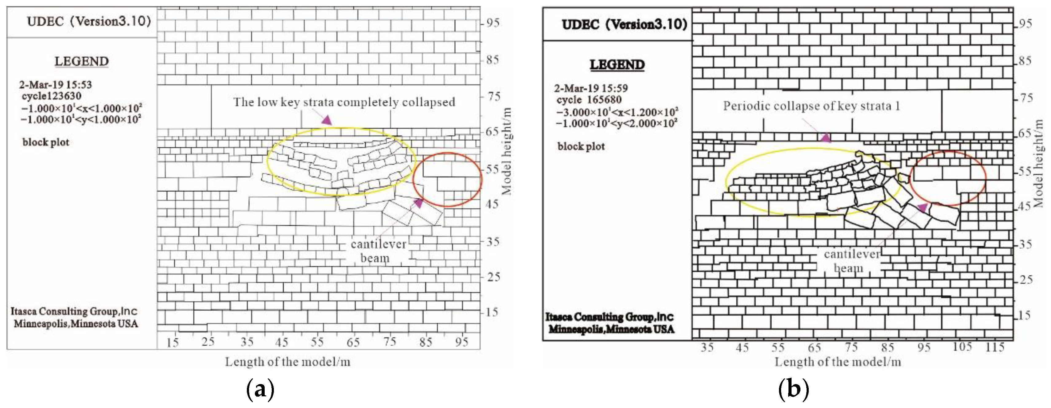
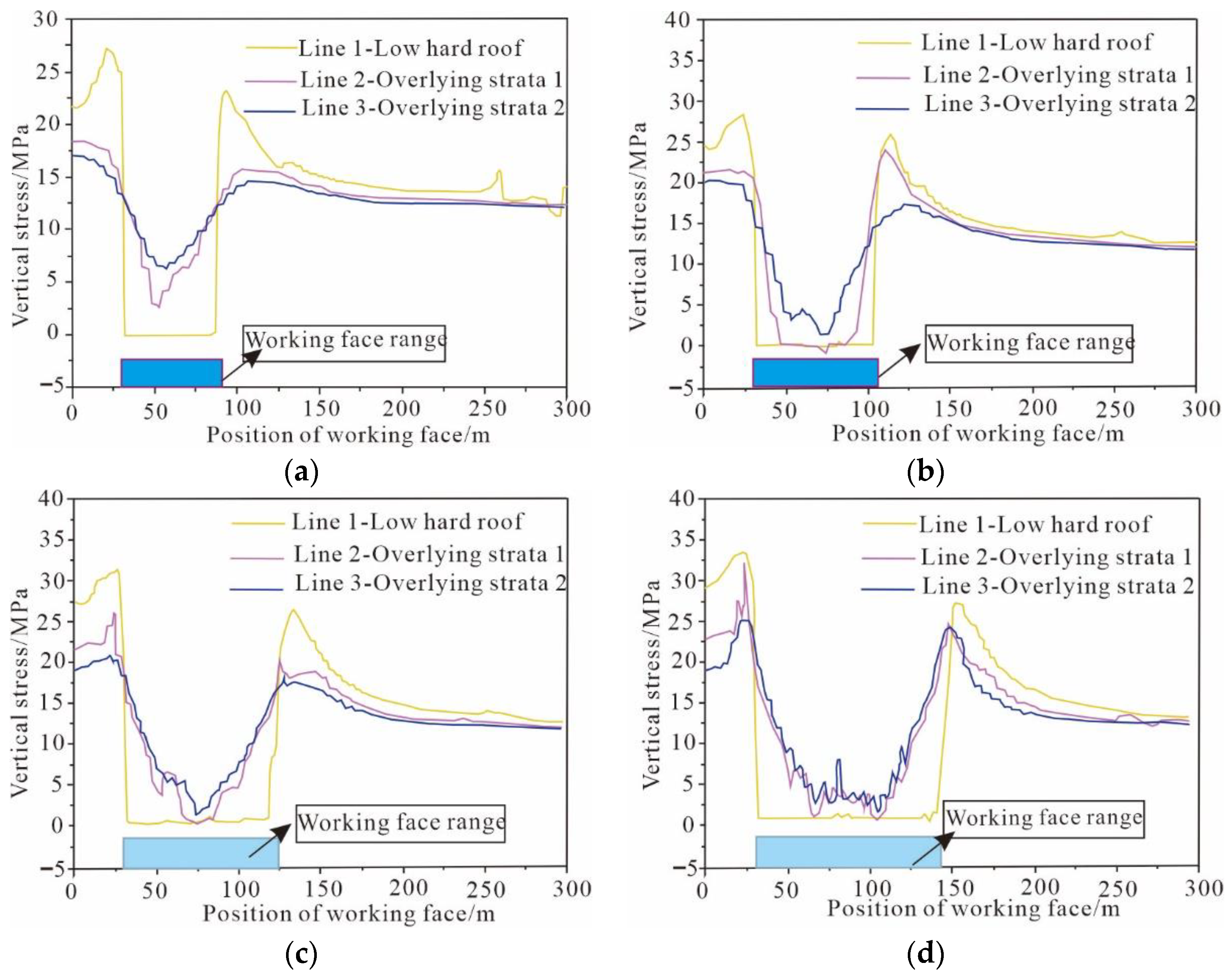
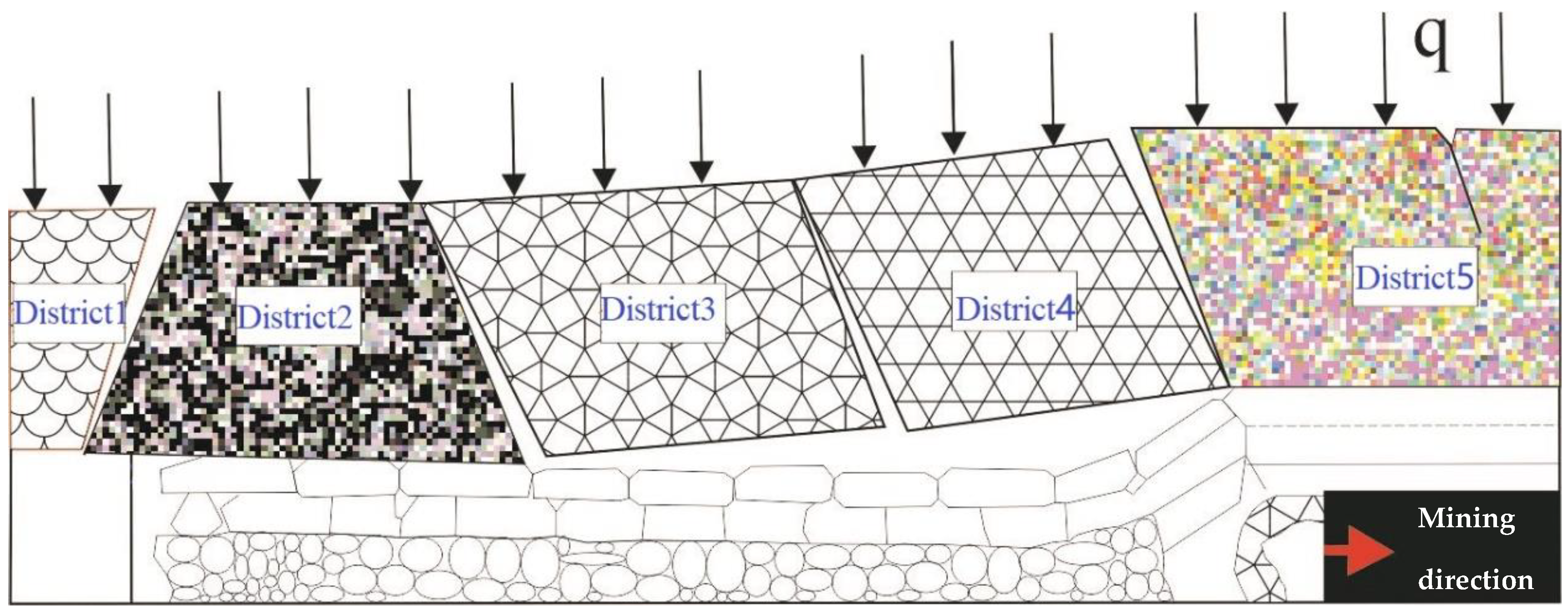
3.1. Breaking Characteristics of Key Overburden Strata

The Universal Distinct Element Code (UDEC), a universal discrete element method program in the category of discontinuous medium mechanics methods, is used to simulate and analyze the development and stress distribution characteristics of the surrounding rock of the stope under mining. The simulation focuses on analyzing the dynamic fracture characteristics and stress field changes of the key layers of the low hard roof. The model selects the coal seam direction, namely the advance direction of the working face, as the X-axis direction, and the vertical direction along the vertical working face as the Y-axis direction. Among them, the length of the working face in the advancing direction is set to 300 m, and the height of the overburden layer is set to 100 m, so the model size is 300 m × 100 m, and the coal seam thickness is 6.2 m. The physical and mechanical parameters of the model are determined by the average of the laboratory results of about 20 groups of rock samples, as shown in Table 1. The model is shown in Figure 1.
In order to eliminate the boundary effect, according to the actual production situation of the working face, 40 m of boundary coal is left on both sides. The lower end of the model adopts all constraints, the left and right sides respectively restrict the displacement in the x direction, and the upper end surface is the mechanical boundary of the free end. The top surface of the model is subjected to the overburden stress (equivalent depth of 400 m). According to the calculation formula of the weight of the rock mass (P = γH), the external vertical stress of the initial model of the overburden is 8 MPa. During coal seam excavation, three survey lines are arranged on the low hard roof, overlying strata 1 and overlying strata 2, respectively, which are marked as survey lines 1 to 3 from bottom to top, respectively. A total of 120 m of advance is set in the simulation set, and the grid is divided into 2.5 m × 5.0 m, which can be used for data extraction at intervals of 5 m.
It can be seen from Figure 2, as the working face advanced to 60 m, the key layer of the low-level hard roof collapses for the first time. The weak rock layer also fell, forming a clear separation layer from the overlying hard rock layer. As the working face advances to 75 m, the low-position hard roof periodically collapses, and the overlying weak rock layer also falls, causing the overlying hard rock layer to sink and deform. The periodic pressure step is 15 m. When the working face is advanced to 95 m and 115 m, the low hard roof undergoes two cycles of pressing, and the periodic pressing steps are about 10 m and 20 m. The low hard roof presents a cantilever beam structure, and the overlying hard rock layer is bent and overhangs. The length of the dew keeps increasing.
The model is used to lay out three survey lines, collect the data of each monitoring point, and plot the changes in overlying rock stress under different mining distances, as shown in Figure 3.
When the working face advances to 60 m, the key layer of the low hard roof breaks for the first time, forming a large mining support stress in front of the coal wall of the working face. The coal body is deformed and damaged, the bearing capacity is lost, and the stress transfers to the deep part of the coal body, with a peak support stress of 27.50 MPa, a stress concentration coefficient of 2.20, and a peak position of about 10.0 m in front of the working face. When the working face is advanced to 75 m, 95 m, and 115 m, the key layer of the low hard roof collapses periodically, and the mining support stress increases compared with the initial collapse. The peak support stress is 28.05 MPa, 30.05 MPa and 32.5 MPa, respectively. The concentration coefficients are 2.24, 2.40, and 2.60, and the peak positions are located at 8.4 m, 8.8 m, and 9.4 m in front of the work surface.

3.2. Disaster Mechanism of Fully Mechanized Caving Mining with Hard Roof and High Mining Height

It can be seen from the simulation results that under the condition of large mining and high mining, the range of overlying rock fracture rotation is significantly increased, leading to the key layer of low hard rock entering the range of “caving zone” and appearing in the form of “cantilever beam” structure in the process of fracture movement. The thick and hard roof completes the accumulation of a huge amount of elastic energy during the bending and subsidence, which provides internal power for the instability and movement of the overburden structure, and at the same time releases a large amount of energy to the working face at the moment of its breaking, thereby triggering the appearance of strong rock pressure. Therefore, based on the “cantilever beam theory”, the fracture mechanics model is established, as shown in Figure 4.
With the continuous development of mining, the overburden Q(t) of the mined-out space roof varies with time, and its function is expressed as nt, where n is a parameter related to the physical and mechanical properties of coal, and the roof rock itself is a uniformly distributed load q. In the suspended roof stage, the roof rock layer is bent and deformed under the action of the overburden and its own weight, accumulating elastic energy. The flexural equation is as follows:
ω 1 = q x 2 24 E I ( x 2 4 l d + 6 L d 2 )
where, ω1 is the bending subsidence of the roof rock layer, Ld is the length of the suspended roof, E is the rock elastic modulus; I is the moment of inertia of the beam structure. The limit span Lmax at the moment of breaking of the cantilever and the maximum bending deformation Wmax at the end are, respectively:
L max = h R t 3 ( n t + q )
W max = ( m t + q ) L max 4 8 E I
where, Rt is the ultimate tensile strength at both ends of the roof rock formation; t is the time.
U s = ( n t ) 2 L d 5 20 E I
The elastic energy Us and the energy Uh at the moment of breaking of the cantilever beam accumulated during the bending deformation stage are:
U h = ξ 1 U s
The thick and hard rock formation is accompanied by energy accumulation and release before and after the fracture. Assuming that the physical process is a closed system, there is no heat exchange with the outside world. According to the analysis of the first law of thermodynamics, we can see that:
Δ U = U s U h
where, ΔU is the released strain energy, which is the energy released after the coal and rock formation becomes unstable, as is also the energy that causes dynamic load and strong rock pressure disasters; Us is the hard roof accumulation energy; Uh is energy dissipated by fracture instability, energy consumed during fracture instability and fracture expansion, strength reduction and dissipation of thick and hard rock. That is, when ΔU > 0, the thick and hard rock layer will release energy to the working face after it loses stability, which may cause instability phenomena such as support crushing and equipment dumping.
Through energy simulation analysis, it can be found that the initial fracture of the low-level hard roof was compressed above the coal wall of the working face, bending and sinking occurred, and elastic energy continued to accumulate (Us became larger). The peak strain energy density before fracture reached 156.47 KJ/m3, the residual energy released after breaking is 137.2 KJ/m3, the suspended roof area of the first collapse of the hard roof is generally more than 20,000 m2, and the released energy reaches 3.85 × 10⁵ KJ/m3 > 0, which is easy to cause impact dynamic disasters (Figure 5).
Under the conditions of fully mechanized caving mining with large mining heights, the low-level roof rock formations collapsed in the form of large “cantilever beams”. Because the low-level hard roof is strong in its integrity and easy to form large-area suspended roofs, it accumulates a large amount of elastic energy. The fracture collapse has a large degree of block, the released energy is small, and it is easy to release huge impact kinetic energy after breaking.

4. Advanced Weakening of the Hard Roof

4.1. Principles of Prevention and Control of Hard Roof and Strong Underground Pressure Disasters

According to the analysis of the occurrence characteristics of low-level hard rock layers and the fracture structure and stress field evolution law, it can be seen that the mining face under the hard roof rock layer is prone to strong underground pressure, and the thick hard rock layer is the main power source. From the analysis of the relationship between hard roof accumulation and breaking and destabilizing energy dissipation, it can be seen that the difference between the two is the energy released after destabilization, which is the source of power for the occurrence of strong mine pressure disasters at the working face. Based on this, a control technology based on the energy principle is proposed. By fracturing the hard roof in advance, reducing the suspended roof area, increasing the breaking frequency, reducing energy accumulation, and increasing energy dissipation (Figure 6).
In view of the hard roof disasters, zoned weakening control is carried out. The low-level thick hard rock layer is weakened and reformed by the underground directional long borehole open-hole segmented hydraulic fracturing technology to realize the timely and complete fall of the low-level thick hard rock layer and the direct roof to increase the fracture release energy, reduce the energy accumulation of the suspended roof, and support the high hard roof.

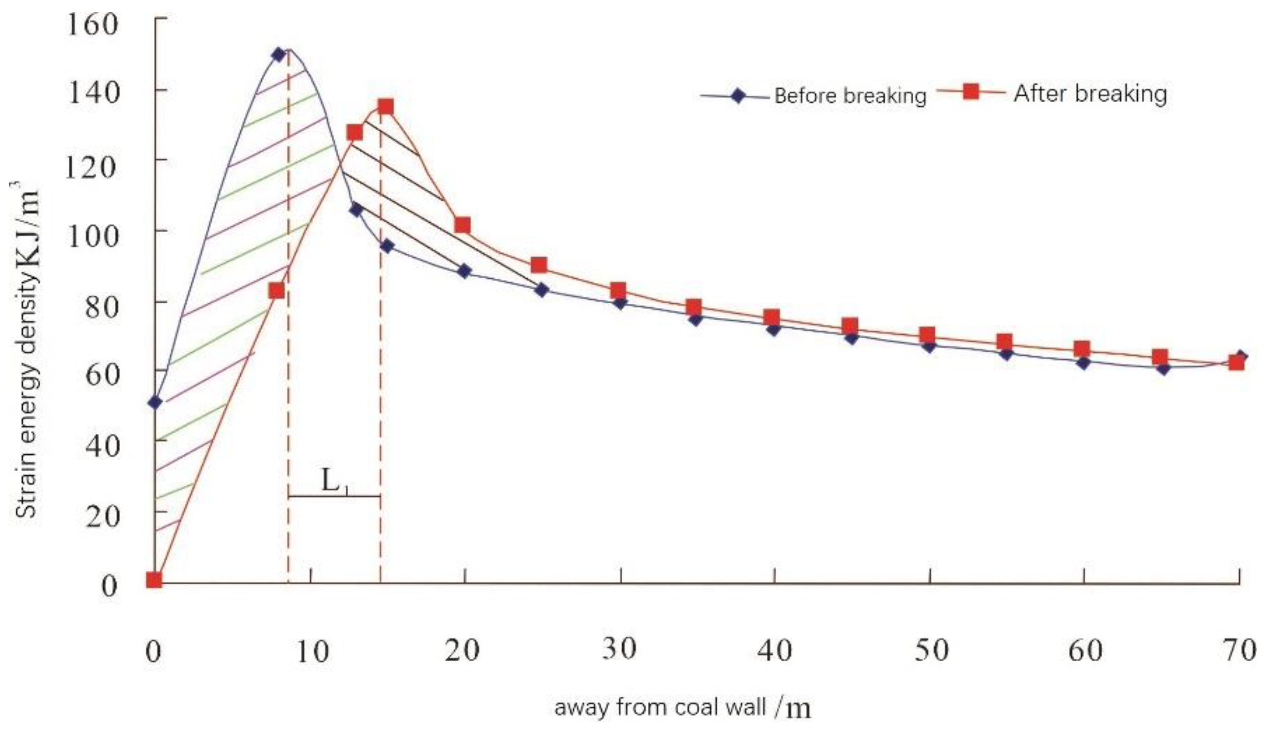
4.2. Reasonable Length of Suspended Roof for Prevention of Dynamic Disasters of Hard Roof

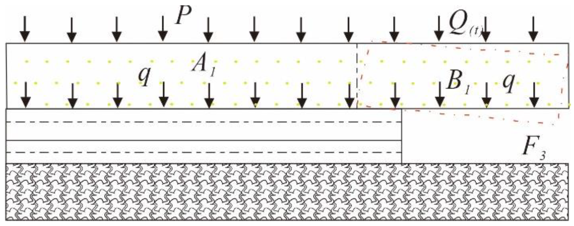
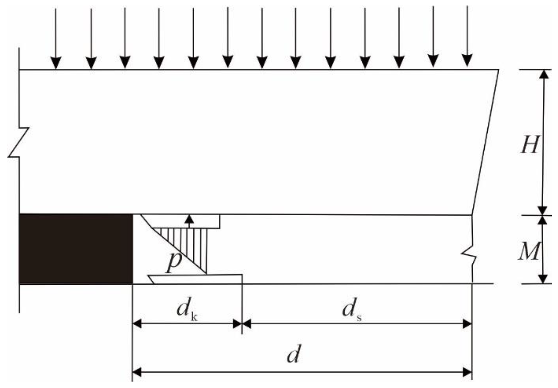
4.2.1. Mechanical Analysis

The hard roof rock layer overlying the coal seam can be regarded as an elastic strain beam clamped between the upper roof and the coal seam and based on the coal seam. After the first break of the hard roof, with the continuous advancement of the working face, one end of the beam is fixed to the coal wall in front of the working face, and the other end is suspended above the goaf to form a “cantilever beam” structure. The working face continues to advance, and the “cantilever beam” will periodically break.
There are three main types of load for the hard roof “cantilever beam” structure, namely, uniformly distributed load, non-uniformly distributed load and concentrated load. The maximum bending moments of the above load forms all occur at the fixed end of the coal wall, and the uniform load distribution is the most common. Based on this, the “cantilever beam” mechanical model is established, and the specific force situation is simplified as shown in Figure 7. In the Figure 7, P is the resistance at the top line of the support; H is the thickness of hard rock; M is the mining height; dk is the controlled top distance of the support; ds is the suspended roof length of the rock beam behind the support; d is the length of “cantilever beam” supported by the bracket. The supporting force of the support in the roof control area is simplified as a triangular distribution.

4.2.2. Determination of Reasonable Ceiling Length

According to the “cantilever beam” mechanics model established in Figure 7, under the established support device conditions, suppose the support strength of the working face support to the roof is [P0], the length of the “cantilever beam” that the support bears is d, and d = dk + ds. Breaking of the “cantilever beam” above the coal wall is the most dangerous situation for dynamic disasters, and there are:
[ P 0 ] d k 1 2 d k = d m γ 1 2 d = d q 1 2 d
[ P 0 ] = q d 2 d k 2 = q ( d k + d s ) 2 d k 2
where, [P0] is the support strength of the support when the roof is cyclically broken.
Under the condition of the given support of the working face, since the supporting strength of the working face cannot be infinite, it has the design supporting strength, that is, the limit value. Assuming this value is [P], in order to ensure the safe production of the working face, the support will be affected when the roof breaks periodically. The supporting strength [P0] is not greater than the design supporting strength of the bracket [P], that is:
[ P 0 ] = q ( d k + d s ) 2 d k 2 [ P ] d s d k ( [ P ] q 1 ) }
Through the above analysis, the reasonable suspension length d of the hard roof based on the design support strength of the bracket is obtained as:
d d k [ P ] q

4.3. Advanced Control Technology of Hard Roof Dynamic Disaster

Aiming at strong mine pressure dynamic disasters caused by a hard roof, based on the analysis results of the disaster prevention energy principle, a directional long borehole segmented hydraulic fracturing advanced weakening control technology is proposed (Figure 8). It is mainly based on the identification result of the reasonable length of the hard roof suspended roof, adopts the “double-sealed single card” segmented volume fracturing process, and the large displacement and high pressure are injected into the sealed space instantaneously, which promotes the formation of main cracks in the hard roof, while making natural cracks. The continuous expansion and shear slip of brittle rocks realize the connection between natural cracks and rock bedding and joints, and induce secondary branch cracks and secondary secondary cracks on both sides of the main crack, and so on, forming multiples. The complex fracture network intertwined with the main fracture and the secondary fracture system, thereby destroying the integrity of the target horizon, reducing its overall strength, reducing the suspended roof area of the hard roof, reducing the stepping distance of the roof, and realizing the effective control of the reasonable suspended roof length.

5. Engineering Application

5.1. Project Overview

The length of the 42,202 working face of Shendong Buertai Coal Mine is 4485.24 m, the working face width is 320 m, the mining height is 6.5 m, and the mining cycle progress is 0.8 m; the thickness of the coal seam is 1.8–2.2 m, and the average thickness is 2 m, including Gangue 1–2 layers; the basic roof of the coal seam is developed with high-strength, thick, and dense fine-grained sandstone, with an average uniaxial compressive strength of 64.73 MPa, tensile strength of 9.26 MPa, elastic modulus of 14.0 GPa, and hard roof rock; the beam thickness is 24.06 m; the coal seam floor is sandy mudstone. In the process of working face mining, strong mineral pressure disasters such as support crushing, cylinder explosion, instantaneous bottom heave and ejection often occur.
The working face adopts double-column shielded top coal caving hydraulic support. The designed rated working resistance of the support is 18,000 kN/frame, the designed support strength is 1.8 MPa, and the control roof distance of the support is 5.20 m. Physical and mechanical parameters of the 4-2 coal seam and roof rock are shown in Table 2.

5.2. Experimental Formation

Under the condition of thick and hard roof development, along with the high mining height and high efficiency production mode, the roof is prone to large deformation, movement and sudden breakage of the overburden. During the breaking process of the roof rock layer, the mechanical equilibrium state of the orebody-surrounding rock system is destroyed and an instantaneous vibration larger than the energy consumption is released, which induces microseismic events. Each sudden release of energy is accompanied by the destruction of the stress balance state. At the same time, seismic waves propagate outward from the physical damage point (seismic source), which can intuitively and accurately locate the energy source to suppress the key horizon. Through real-time monitoring and processing of microseismic data, the key energy sources for overlying strata breaking during mining are analyzed, and the target horizon is optimized for treatment.
Through the analysis of the microseismic data monitoring, using a KJ551 system with a detection frequency band width of 60–1500 Hz and a sensitivity of 100 V/m/s, during the mining process it can be seen that the fracture energy of the 42,202 working face is greater than 50,000 J, and the energy with a Richter scale of 1.52 or more is concentrated in the position of the fine-grained sandstone 25–35 m from the coal roof (Figure 9). Combined with the analysis of roof rock strata structure and mechanical characteristics, this location is the source of large energy release for roof suspension and breaking, and is the direct target of roof control.

5.3. Reasonable Ceiling Length Control

5.3.1. Hard Rock Beam and Its Overlying Rock Load

According to the key layer theory, the load considering the influence of the overlying n layers on the rock beam with hard roof is q 1 | n + 1 and can be expressed as:
q 1 | n + 1 = E 1 h 1 3 1 n ( γ i h i + q n + 1 ) i = 1 m + 1 E i h i 3
Substituting the test results shown in Table 2 into Equation (11), the load q1 of the hard rock beam itself can be obtained as follows:
q 1 = γ 1 h 1 = 617.22   Kpa
When considering the effect of the second layer of sandy mudstone on the first layer of fine-grained sandstone, the expression is as follows:
( q 2 ) 1 = E 1 h 1 3 ( γ 1 h 1 + γ 2 h 2 ) E 1 h 1 3 + E 2 h 2 3 = 831.50   Kpa
Through the calculation of the above formula, when calculated to the position of the medium-grained sandstone of the 11th layer of the coal roof:
( q 11 ) 1 = 1027.71   Kpa < ( q 10 ) 1 = 1221.84   Kpa
Then take (q10)1 as the load acting on the hard rock beam as 1221.84 (kN·m−2).

5.3.2. Determination of Reasonable Ceiling Length

If q = 1221.84(kN·m−2), [P] = 18,000 kN, dk = 5.40 m, and put it into Formula (9), the reasonable suspended roof length of the working face is 20.73 m.

5.4. Application of Hard Roof Control Technology

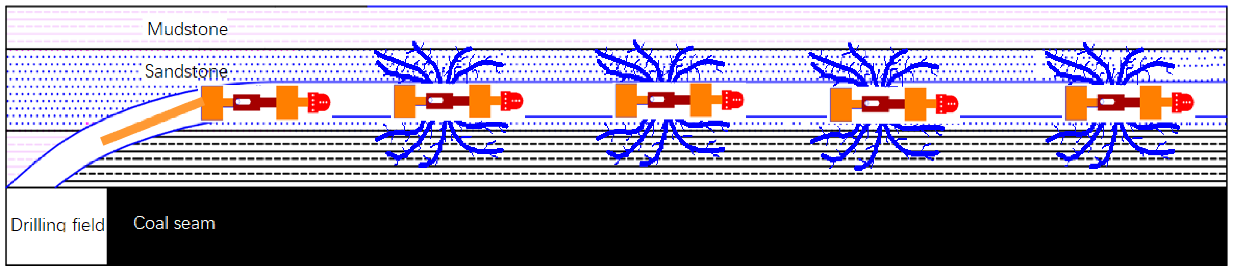
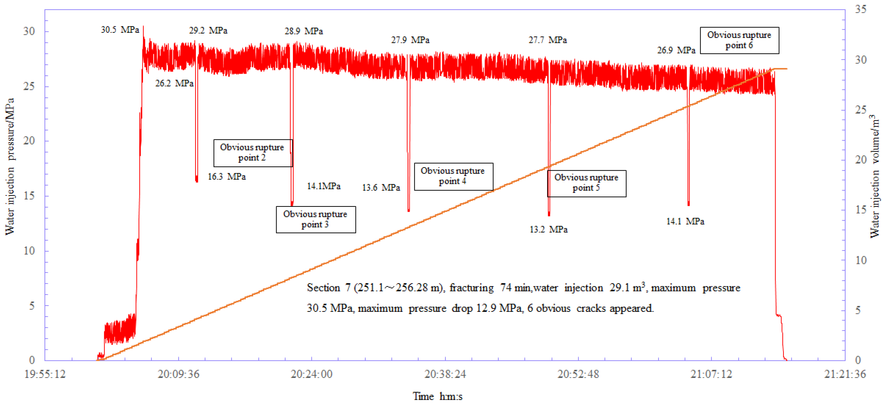
5.4.1. Construction of Staged Fracturing Project

Aiming at the characteristics of the hard roof with large thickness, high strength, strong compactness, high compressive strength during the stoping process, and difficulty in collapse, the calculation results are controlled in combination with reasonable suspended roof length. Relying on the width of the working face, a single drilling field adopts three directional long boreholes arranged at equal intervals along the direction of the coal seam. The borehole is 490–600 m long, and the “double-sealed single-card” open-hole segmented hydraulic fracturing technology (Figure 9) is used to perform fracturing construction from the inside to the outside of the borehole. The fracturing position is at the level of entering the target horizon section, single hole effective horizontal section 310–420 m, and the fracturing with a single hole is 8–15 sections. The cumulative water injection volume with a single hole is 280–540 m3, the maximum pressure is 30.5 MPa, the minimum pressure is 12.4 MPa, and the maximum pressure drops 12.9 MPa. The cumulative pressure exceeds 3.0 MPa 160 times, and the fracturing effect is obvious (Figure 10).

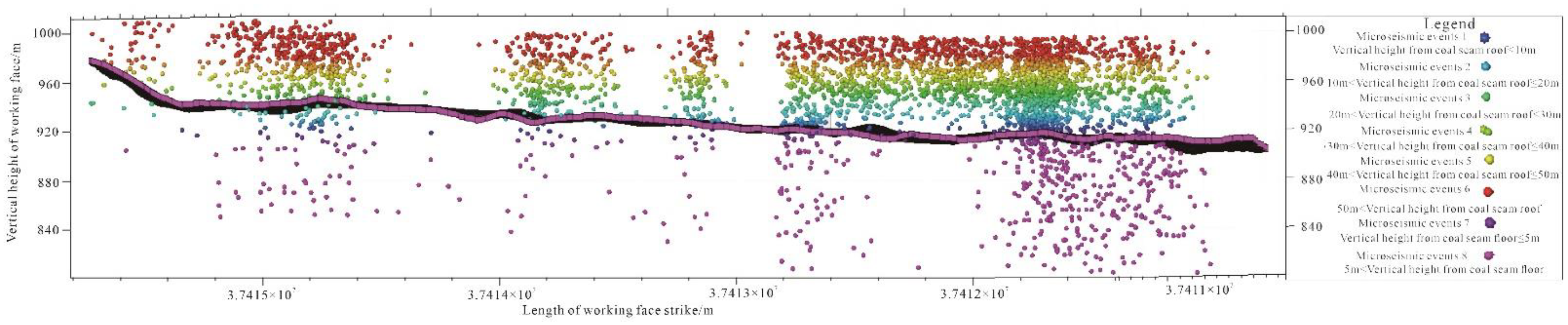
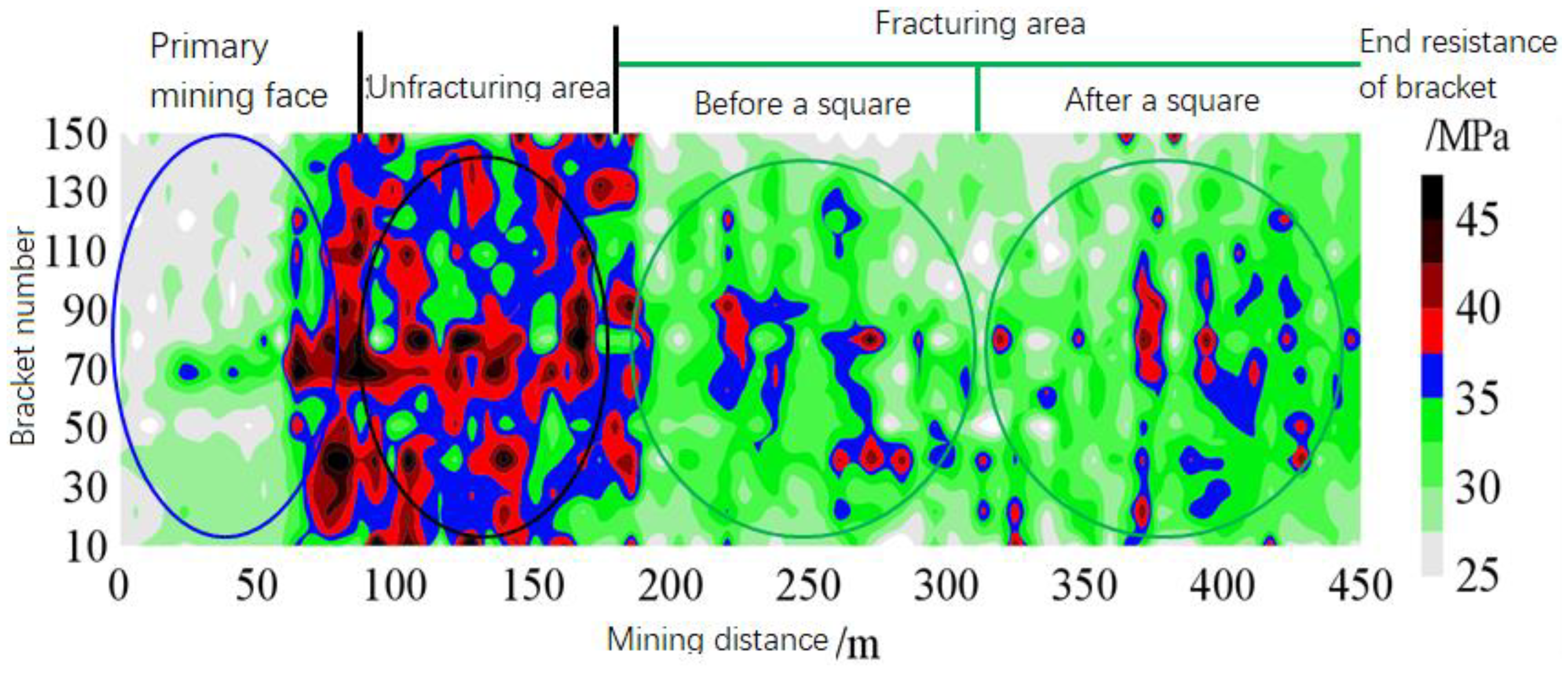
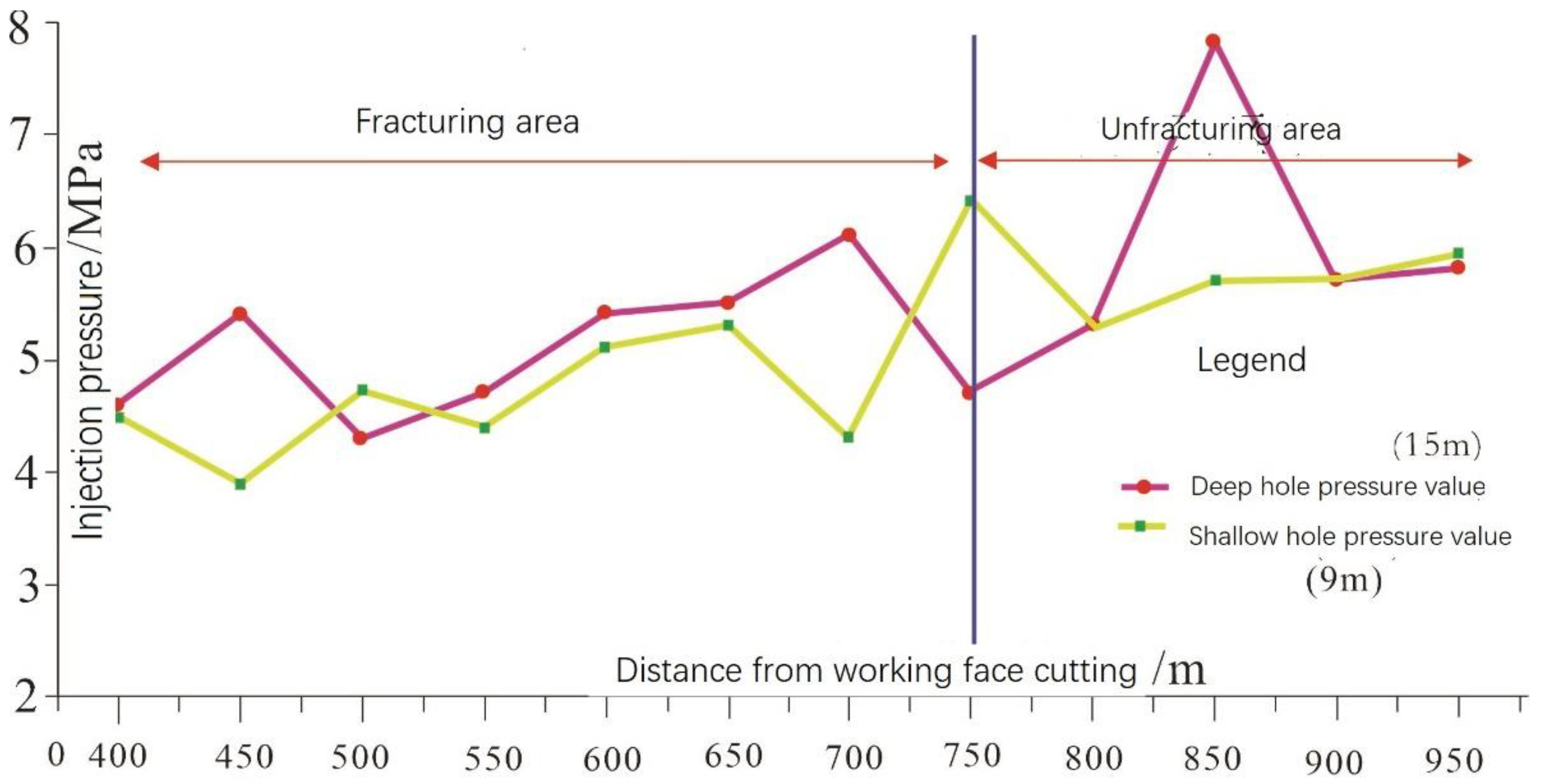
5.4.2. Evaluation of Fracturing Treatment Effect

By underground tracking and monitoring, and support data acquisition, a variation diagram of support resistance at the selected work position was drawn (Figure 11). Before entering the fracturing stage, the maximum pressure in each cycle was 53.8–59.1 MPa (1 bar = 0.1 MPa), and the average value was 55.45 MPa; the mean pressure was 41.6–44.7 MPa during the pressure period, and the average value was 42.97 MPa. During normal propulsion, the stable pressure of the support is 29.7 MPa, the dynamic load coefficient is 1.41–1.52, with an average of 1.46. The periodic pressure step distance is 24.2–26.3 m, with an average of 25.5 m, all exceeding the reasonable suspension length, and the pressure range is wide. After entering the fracturing stage, the maximum pressure in each cycle is 46.8–50.1 MPa and the average value is 48.00 MPa. The average pressure was 37.5–40.6 MPa, and the average was 39.02 MPa. During normal propulsion, the stable pressure of the support is 29.02 MPa, the dynamic load coefficient is 1.32–1.38, with an average of 1.34, and the periodic pressure step distance is 16.5–18.2 m, with a small pressure range.
After the roof segmented hydraulic fracturing is weakened, the roof pressure step, dynamic load factor, and maximum pressure are reduced by 32.16, 5.79 and 13.44%, respectively. The effectiveness of roof weakening after fracturing is verified.
Using the surrounding rock stress monitoring equipment, a set of surrounding rock stress monitoring equipment are installed every 50 m. Monitoring boreholes are divided into two types, 15 m deep holes and 9 m shallow holes. A comparative analysis is made for the fracturing area and the unfracturing area; the coal wall stress monitoring results show that after the fracturing is weakened, the advanced stress of the deep and shallow holes is reduced from 4.5–7.8 MPa to 3.5–5.5 MPa, a drop of more than 20%, and the fracturing is weakened After that, the stress of surrounding rock along the channel was effectively weakened (Figure 12, Table 3).

6. Hard Roof Disaster Control Mechanism

In the process of fracture and collapse of the hard roof of the coal seam, on the one hand, the stress of the coal and rock mass below will be significantly increased. On the other hand, the elastic energy accumulated in the coal and rock mass should be superimposed with the energy released by the fracture failure of the key layer, causing large-scale ore shock or rock burst. The active instability of the hard roof will lead to the passive instability of the underlying rock structure. Then the energy released by the hard roof is:
U = v i = 1 n ( U v i + 1 2 ρ i ( d u i d t ) 2 + ρ i g u i ) d V
where, n is the total number of rock formations broken along with the key layer; ui is the displacement of the rock formation; Uv is the elastic strain energy stored in the rock formation.
U V = ( 1 2 μ ) ( 1 + 2 λ ) 2 6 E γ 2 H 2
where, λ is the ratio of the average horizontal principal stress to the vertical stress; ρi is the density of the i rock layer, and g is the acceleration of gravity.
In the formula, the first term is the elastic strain energy of the rock with a hard roof; the second term is the kinetic energy in the process of roof failure; and the third term is the gravitational potential energy of the downward movement of the structure after breaking. It can be seen from the formula that the energy released by the breaking of a hard roof is directly related to the length of the suspended roof of the rock formation. Therefore, controlling the length of the suspended roof, that is, reducing the length of the roof to press the step distance, is an important way to solve the hard roof disaster.
The open-hole segmented fracturing technology of directional long boreholes in underground coal mines can realize man-made large-scale cracks in hard rock formations and change the stress distribution and fracture characteristics of the rock formations. The final propagation direction of fractures is always perpendicular to the minimum principal stress direction. According to the three-dimensional stress σH, σv, and σh, the fracture propagation patterns can be roughly divided into three situations. When σH > σv > σh, along the directional drilling horizontal fracturing period in the vertical direction of the working face mining ellipsoid fissure network formation, the formation of this type of fracture of hard rock segmentation in block sections, reduces the integrity of the rock strata, effectively reducing the roof pressure step, and the rock breaking energy release intensity will suddenly and sharply weaken (Figure 13a). When the maximum and minimum horizontal principal stress directions of the rock formation are different and σH > σh > σv is satisfied, a horizontal fracture surface network is formed in the direction perpendicular to the working surface after the horizontal section is fractured. The existence of the fracture surface realizes the thick and hard roof. Layering reduces the effective thickness of the hard top plate, as shown in Figure 13b.
When σv> σH> σh is satisfied, that is, the vertical stress of the rock formation is the largest, and the crack propagation pattern is shown in Figure 13c. At this time, a near-linear fracture surface dominated by vertical fractures is formed, the fracturing target layer has a small coverage area of fracturing fractures, the control of the rock formation is limited, the engineering volume is large, and the control effect of the strong rock pressure on the working face is not good.
Based on the Kaiser method, the in-situ stress distribution characteristics of the Shendong mining area are obtained. Most of the coal seams in the Shendong mining area are buried below 400 m. After testing, the Shendong mining area is buried less than 200 m and the stress state is σH > σh > σv; at more than 200 m, the stress state is σH > σv > σh which is in line with the fracture formation conditions of modes a and b, that is conducive to the reconstruction of the hard roof.
Through segmented hydraulic fracturing, the hard roof rock layer is cracked into irregular blocks, and weak planes are formed between each block. When the supporting pressure increases, each block will slide along the weak plane to release energy and reduce the stress of the rock formation. “Fracturing reduces the energy storage block and reduces the energy storage capacity” strong mine pressure disaster control. The elastic energy uv0 of rock accumulation with volume V0 is:
u v = V 2 E [ σ 1 2 + σ 2 2 + σ 3 2 2 δ ( σ 1 σ 2 + σ 2 σ 3 + σ 3 σ 1 ) ]
In the formula, σ1 is the first principal stress; σ2 is the second principal stress; σ3 is the third principal stress; δ is the Poisson’s ratio of the rock mass; E is the elastic modulus of the rock mass.
It can be seen from Equation (17) that the elastic energy of the rock mass is positively correlated with the rock mass and the surrounding rock stress. Therefore, when a complete rock mass is fractured into several small pieces, its energy is dispersed to each small piece, and as the rock mass decreases, the accumulated energy decreases (Figure 14).
In the fracturing process, the rock mass is subjected to high-pressure water, and multiple processes such as “fracture initiation-fracture extension-secondary cycle initiation” occur. This process is a single irreversible release process accompanied by energy consumption. The larger the fractured fracture scale, the better the overall pressure release effect is. In the process of energy release, an effective fracture network system is formed, the stress field is reformed to increase the relief area (reduce the concentrated pressure), and a new stress concentrated transfer area is formed, so as to realize the transfer and dissipation of stress on the roof.

7. Conclusions

(1)
During the mining of thick and hard roof coal seams, the overlying hard roof is suspended in a large area, the cantilever beam is broken, the fracture is large, the energy released by the fracture is small, and huge impact kinetic energy is easily released after breaking, forming a strong stope mine pressure.
(2)
A staged fracturing control technology for the hard roof is proposed, to weaken the low-level thick hard rock layer, reduce the suspended roof length, increase the breaking frequency, and reduce energy agglomeration. A mechanical model for judging the length of the reasonable suspended roof was constructed, and the reasonable length of the suspended roof was quantitatively judged.
(3)
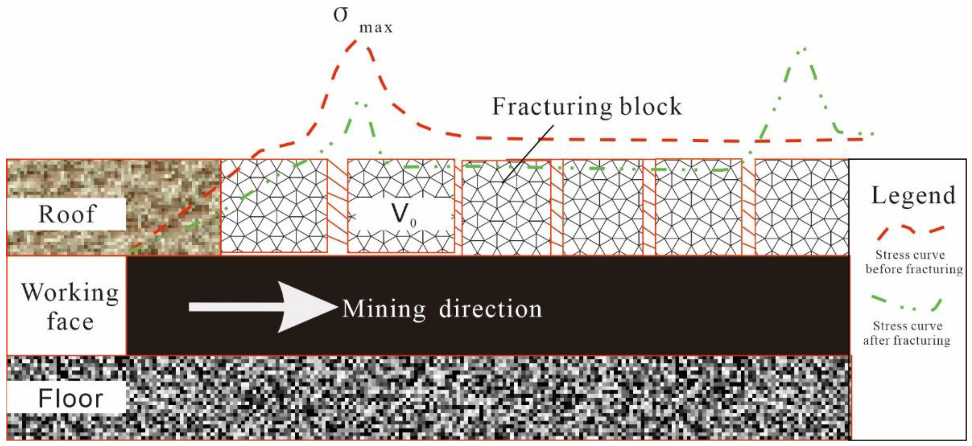
After the roof segmented hydraulic fracturing, the roof pressure step distance is effectively reduced by 32.16%, which realizes the effective control of the hard roof and the strong mine pressure disaster, and verifies the reasonable suspended roof. The hard roof rock mass is fractured into irregular blocks, the roof pressure step is reduced, the energy storage block is reduced, the energy storage capacity is reduced, and fractures are formed. In the process, it is realized that energy consumption, stress transfer and dissipation, effectively control strong mine pressure disasters.

Author Contributions

K.Z., Y.L. and T.Z. designed and wrote the paper, K.Z. performed the experiments, and J.Z. supervised the paper writing. All authors have read and agreed to the published version of the manuscript.

Funding

This research was funded by the Natural Science Foundation of Anhui Province (2008085QD191 and 1908085ME144), the National Key Research and Development Program of China (2017YFC0804101), and the Independent Research fund of the State Key Laboratory of Mining Response and Disaster Prevention and Control in Deep Coal Mines (Anhui University of Science and Technology) (No. SKLMRDPC19ZZ06).

Acknowledgments

The authors are grateful to Yuan and Xu for their assistance.

Conflicts of Interest

The authors declare no conflict of interest.

References

  1. Zhang, S.Z.; Fan, G.W.; Chai, L.; Li, Q.Z.; Chen, M.W.; Luo, T.; Ren, S. Disaster Control of Roof Falling in Deep Coal Mine Roadway Subjected to High Abutment Pressure. Geofluids 2021, 2021, 8875249. [Google Scholar] [CrossRef]
  2. Gonzalo, J.A.; Gero, M.B.P.; Fernández, M.I.Á.; Vigil, A.E.L.; Nicieza, C.G. Roof tensile failures in underground excavations. Int. J. Rock Mech. Min. Sci. 2013, 58, 141–148. [Google Scholar] [CrossRef]
  3. Xia, B.; Zhang, X.; Yu, B.; Jia, J. Weakening effects of hydraulic fracture in hard roof under the influence of stress arch. Int. J. Min. Sci. Technol. 2018, 28, 951–958. [Google Scholar] [CrossRef]
  4. Zheng, J.; Ju, W.; Sun, X.; Jiang, P.; Zheng, Y.; Ma, Z.; Zhu, L.; Yi, B. Analysis of Hydro-fracturing Technique Using Ultra-deep Boreholes for Coal Mining with Hard Roofs: A Case Study. Min. Met. Explor. 2021, 38, 471–484. [Google Scholar] [CrossRef]
  5. Sun, Y.; Fu, Y.; Wang, T. Field application of directional hydraulic fracturing technology for controlling thick hard roof: A case study. Arab. J. Geosci. 2021, 14, 438. [Google Scholar] [CrossRef]
  6. Zheng, K.G.; Zhang, T.; Zhao, J.Z.; Liu, Y.; Yu, F. Evolution and management of thick-hard roof using goaf-based multistage hydraulic fracturing technology—A case study in western Chinese coal field. Arab. J. Geosci. 2021, 14, 876. [Google Scholar] [CrossRef]
  7. Chen, Y.; Zhu, S.; Wang, Z.; Li, F. Deformation and failure of floor in mine with soft coal, soft floor, hard roof and varying thicknesses of coal seam. Eng. Fail. Anal. 2020, 115, 104653. [Google Scholar] [CrossRef]
  8. Zhang, M.; Jiang, F.X. Rock burst criteria and control based on an abutment: Tress-transfer model in deep coal roadways. Energy Sci. Eng. 2020, 8, 2966–2975. [Google Scholar] [CrossRef]
  9. Jiang, F.X.; Liu, Y.; Zhang, Y.C.; Wen, J.L.; Yang, W.L.; An, J. A three-zone structure loading model of overlying strata and its application on rock burst prevention. Chin. J. Rock Mech. Eng. 2016, 35, 2398–2408. [Google Scholar]
  10. Liu, S.H.; Pan, J.F.; Xia, Y.X. Study on induced mechanism of rock bursts by fracture movement of hard magmatic beds. Chin. J. Rock Mech. Eng. 2019, 38, 499–510. [Google Scholar]
  11. Lv, J.G.; Jiang, Y.D.; Li, S.G.; Ren, S.D.; Zhang, Z.C. Characteristics and mechanism research of coal bumps induced by faults based on extra thick and hard roof. J. China Coal Soc. 2014, 39, 1961–1969. [Google Scholar]
  12. Zhang, K.X. Mechanism study of coal bump under tectonic and ultra-thick conglomerate coupling conditions in mining roadway. Chin. J. Rock Mech. Eng. 2017, 36, 1040. [Google Scholar]
  13. Liu, C.Y.; Yang, J.X.; Yu, B. Rock-breaking mechanism and experimental analysis of confined blasting of borehole surrounding rock. Int. J. Min. Sci. Technol. 2017, 27, 795–801. [Google Scholar]
  14. Liu, C.Y.; Yang, J.X.; Yu, B.; Yang, P.J. Destabilization regularity of hard thick roof group under the multi gob. J. China Coal Soc. 2014, 39, 395–403. [Google Scholar]
  15. Dou, L.M.; Yang, S.X. Prevention and Control of Rock Burst Disaster in Coal Mining; China University of Mining and Technology Press: Beijing, China, 2006. [Google Scholar]
  16. Dou, L.M.; Wu, C.; Cao, A.; Guo, W. Comprehensive early warning of rock burst utilizing microseismic multi-parameter in-dices. Int. J. Min. Sci. Technol. 2018, 28, 54–61. [Google Scholar] [CrossRef]
  17. Simser, B. Rockburst management in Canadian hard rock mines. J. Rock Mech. Geotech. Eng. 2019, 11, 1036–1043. [Google Scholar] [CrossRef]
  18. Makowski, P.; Niedbalski, Z. A comprehensive geomechanical method for the assessment of rockburst hazards in under-ground mining. Int. J. Min. Sci. Technol. 2020, 30, 345–355. [Google Scholar] [CrossRef]
  19. Stephansson, O.; Semikova, H.; Zimmermann, G.; Zang, A. Laboratory Pulse Test of Hydraulic Fracturing on Granitic Sample Cores from sp HRL, Sweden. Rock Mech. Rock Eng. 2019, 52, 629–633. [Google Scholar] [CrossRef]
  20. Manouchehrian, A.; Cai, M. Numerical modeling of rockburst near fault zones in deep tunnels. Tunn. Undergr. Space Technol. 2018, 80, 164–180. [Google Scholar] [CrossRef]
  21. Yang, J.; Liu, C.; Yu, B. Application of Confined Blasting in Water-Filled Deep Holes to Control Strong Rock Pressure in Hard Rock Mines. Energies 2017, 10, 1874. [Google Scholar] [CrossRef] [Green Version]
  22. Ha, S.J.; Yun, T.S.; Kim, K.Y.; Jung, S.G. Experimental Study of Pumping Rate Effect on Hydraulic Fracturing of Cement Paste and Mortar. Rock Mech. Rock Eng. 2017, 50, 3115–3119. [Google Scholar] [CrossRef]
  23. Ma, S.; Chen, Y. Application of Hydraulic Fracturing and Energy-Absorption Rockbolts to Improve the Stability of a Gob-Side Roadway in a 10-m-Thick Coal Seam: Case Study. Int. J. Géoméch. 2017, 17, 05017002. [Google Scholar] [CrossRef]
  24. He, J.; Lin, C.; Li, X.; Zhang, Y.; Chen, Y. Initiation, propagation, closure and morphology of hydraulic fractures in sandstone cores. Fuel 2017, 208, 65–70. [Google Scholar] [CrossRef]
  25. Liu, J.; Liu, C.; Yao, Q.; Si, G. The position of hydraulic fracturing to initiate vertical fractures in hard hanging roof for stress relief. Int. J. Rock Mech. Min. Sci. 2020, 132, 104328. [Google Scholar] [CrossRef]
  26. Salimzadeh, S.; Usui, T.; Paluszny, A.; Zimmerman, R.W. Finite element simulations of interactions between multiple hy-draulic fractures in a poroelastic rock. Int. J. Rock Mech. Min. Sci. 2017, 99, 9–20. [Google Scholar] [CrossRef] [Green Version]
  27. Kanaun, S. Hydraulic fracture crack propagation in an elastic medium with varying fracture toughness. Int. J. Eng. Sci. 2017, 120, 15–30. [Google Scholar] [CrossRef]
  28. Khanna, A.; Luong, H.; Kotousov, A.; Nguyen, G.D.; Rose, L.R.F. Residual opening of hydraulic fractures created using the channel fracturing technique. Int. J. Rock Mech. Min. Sci. 2017, 100, 124–137. [Google Scholar] [CrossRef]
  29. Kim, H.; Xie, L.; Min, K.B.; Bae, S.; Stephansson, O. Integrated In Situ Stress Estimation by Hydraulic Fracturing, Borehole Observations and Numerical Analysis at the EXP-1 Borehole in Pohang, Korea. Rock Mech. Rock Eng. 2017, 50, 3141–3155. [Google Scholar] [CrossRef]
  30. Kanaun, S. On the hydraulic fracture of poroelastic media. Int. J. Eng. Sci. 2020, 155, 103366. [Google Scholar] [CrossRef]
  31. López-Comino, J.Á.; Cesca, S.; Niemz, P.; Torsten, D.; Arno, Z. Rupture Directivity in 3D Inferred from Acoustic Emissions Events in a Mine-Scale Hydraulic Fracturing Experiment. Front. Earth Sci. 2021, 9, 392. [Google Scholar] [CrossRef]
  32. Llanos, E.M.; Jeffrey, R.G.; Hillis, R.; Zhang, X. Hydraulic Fracture Propagation through an Orthogonal Discontinuity: A Laboratory, Analytical and Numerical Study. Rock Mech. Rock Eng. 2017, 50, 2101–2118. [Google Scholar] [CrossRef]
  33. Gao, Q.; Ghassemi, A. Pore Pressure and Stress Distributions Around a Hydraulic Fracture in Heterogeneous Rock. Rock Mech. Rock Eng. 2017, 50, 3157–3173. [Google Scholar] [CrossRef]
  34. Guo, J.; Luo, B.; Lu, C.; Lai, J.; Ren, J. Numerical investigation of hydraulic fracture propagation in a layered reservoir using the cohesive zone method. Eng. Fract. Mech. 2017, 186, 195–207. [Google Scholar] [CrossRef]
  35. Gupta, P.; Duarte, C.A. Coupled hydromechanical-fracture simulations of nonplanar three-dimensional hydraulic fracture propagation. Int. J. Numer. Anal. Methods Géoméch. 2018, 42, 143–180. [Google Scholar] [CrossRef]
  36. Lu, Y.Y.; Cheng, L.; Ge, Z.; Xia, B.W.; Li, Q.; Chen, J.F. Analysis on the Initial Cracking Parameters of Cross-Measure Hydraulic Fracture in Underground Coal Mines. Energies 2015, 8, 6977–6994. [Google Scholar] [CrossRef]
  37. Ge, Z.L.; Mei, X.D.; Lu, Y.Y.; Tang, J.R.; Xia, B.W. Optimization and application of sealing material and sealing length for hy-draulic fracturing borehole in underground coal mines. Arab. J. Geosci. 2015, 8, 3477. [Google Scholar] [CrossRef]
  38. Bolintineanu, D.S.; Rao, R.R.; Lechman, J.B.; Romero, J.A.; Jove-Colon, C.F.; Quintana, E.C.; Bauer, S.J.; Ingraham, M.D. Simulations of the effects of proppant placement on the conductivity and mechanical stability of hydraulic fractures. Int. J. Rock Mech. Min. Sci. 2017, 100, 188–198. [Google Scholar] [CrossRef]
  39. Chong, Z.; Li, X.; Chen, X. Effect of Injection Site on Fault Activation and Seismicity during Hydraulic Fracturing. Energies 2017, 10, 1619. [Google Scholar] [CrossRef]
  40. Caswell, T.E.; Milliken, R.E. Evidence for hydraulic fracturing at Gale crater, Mars: Implications for burial depth of the Yel-lowknife Bay formation. Earth Plan. Sci. Lett. 2017, 468, 72–84. [Google Scholar] [CrossRef]
  41. Huang, B.; Liu, C.; Zhang, Q. The reasonable breaking location of overhanging hard roof for directional hydraulic fracturing to control strong strata behaviors of gob-side entry. Int. J. Rock Mech. Min. Sci. 2018, 103, 1–11. [Google Scholar] [CrossRef]
  42. Lei, Q.; Latham, J.P.; Tsang, C.F. The use of discrete fracture networks for modelling coupled geomechanical and hydrological behaviour of fractured rocks. Comput. Geotech. 2017, 85, 151–176. [Google Scholar] [CrossRef]
  43. Yu, B.; Gao, R.; Kuang, T.; Huo, B.; Meng, X. Engineering study on fracturing high-level hard rock strata by ground hydraulic action. Tunn. Undergr. Space Technol. 2019, 86, 156–164. [Google Scholar] [CrossRef]
  44. Adachi, J.; Siebrits, E.; Peirce, A.; Desroches, J. Computer simulation of hydraulic fractures. Int. J. Rock Mech. Min. Sci. 2007, 44, 739–757. [Google Scholar] [CrossRef]
  45. Osiptsov, A.A. Fluid Mechanics of Hydraulic Fracturing: A Review. J. Pet. Sci. Eng. 2017, 156, 513–535. [Google Scholar] [CrossRef]
  46. Detournay, E. Mechanics of hydraulic fractures. Annu. Rev. Fluid Mech. 2016, 48, 311–339. [Google Scholar] [CrossRef]
Figure 1. Key layer model of low hard roof in fully mechanized panel with large mining height.
Minerals 11 01405 g001
Figure 2. Overburden movement during simulation by UDEC. (a) Simulated mining 60 m; (b) Simulated mining 75 m; (c) Simulated mining 95 m; (d) Simulated mining 115 m.
Minerals 11 01405 g002aMinerals 11 01405 g002b
Figure 3. Variation characteristics of overburden stress during simulated mining. (a) Simulated mining 60 m; (b) Simulated mining 75 m; (c) Simulated mining 95 m; (d) Simulated mining 115 m.
Minerals 11 01405 g003
Figure 4. Overburden fracture mechanical model.
Minerals 11 01405 g004
Figure 5. Strain energy density evolution law before and after the periodic breakage of the thick and hard roof.
Minerals 11 01405 g005
Figure 6. Schematic diagram of sub-disaster control in fractured zone.
Minerals 11 01405 g006
Figure 7. Mechanical model of cantilever rock beam.
Minerals 11 01405 g007
Figure 8. Segmented hydraulic fracturing process.
Minerals 11 01405 g008
Figure 9. Monitoring results of microseismic energy event.
Minerals 11 01405 g009
Figure 10. Variation law of pressure curve in staged fracturing process (part).
Minerals 11 01405 g010
Figure 11. Panel mining pressure change plan.
Minerals 11 01405 g011
Figure 12. Comparison of surrounding rock pressure changes.
Minerals 11 01405 g012
Figure 13. Fracture morphology under different stress states. (a) σH > σv > σh; (b) σH > σh > σv; (c) σv > σH > σh.
Minerals 11 01405 g013
Figure 14. Staged fracture treatment model of hard roof.
Minerals 11 01405 g014
Table 1. Physical and mechanical parameters of rock strata in the model.
Rock StrataBulk ModulusShear ModulusDensityInternal Friction AnglefCohesive ForceTensile Strength
(Gpa)(Gpa)(kg·m−3)(°)(Mpa)(Mpa)
fine grained sandstone1410.72550387.24.15
mudstone10.657.1925503543.3
coal seam6.541400283.51.8
Table 2. Physical and mechanical parameters of coal seam and roof rock.
No.LithologyLayer ThicknessUnit WeightTensile StrengthElastic Modulus
(m)(kN·m−3)(Mpa)(Gpa)
111-2 upper coal seam1.05142.132
10sandy mudstone3.39262.711.9
91-2 coal seam0.78141.682
8Siltstone18.4827.15.248
7sandy mudstone7.5125.53.628.6
62-2 coal seam2.82141.172
5sandy mudstone14.225.64.218.21
4Medium grained sandstone20.8926.14.458.14
3sandy mudstone14.9725.41.9310.99
2Fine grained sandstone22.86279.2614
1sandy mudstone14.4326.11.5210.56
04-2 coal seam7.23141.082
Table 3. Behavior characteristics of mine pressure during mining.
StageSteady Pressure
(MPa)
Mean Pressure
(MPa)
Maximum Pressure
(MPa)
Dynamic Load CoefficientLoading Distance
(m)
Unfracturing area29.10 42.60 53.80 1.46 24.2
31.10 43.90 56.20 1.41 26.1
29.50 44.70 59.10 1.52 25.0
28.80 42.10 54.70 1.46 25.5
28.10 41.60 53.80 1.48 26.3
29.70 42.90 55.10 1.44 25.7
Mean value29.28 42.97 55.45 1.46 25.5
Fracturing area27.70 37.50 50.10 1.35 18.2
28.60 37.70 46.80 1.32 16.5
29.50 39.00 48.90 1.32 17.2
29.10 39.50 45.60 1.36 17.6
28.80 39.80 48.90 1.38 16.5
30.40 40.60 47.70 1.34 17.8
Mean value29.02 39.02 48.00 1.34 17.3
Reducing(%)0.889.1913.445.7932.16
Publisher’s Note: MDPI stays neutral with regard to jurisdictional claims in published maps and institutional affiliations.

