Article

Hybrid Failure of Cemented Paste Backfill

1
Department of Civil and Mineral Engineering, University of Toronto, Toronto, ON M5S 1A4, Canada
2
Beijing General Research Institute of Mining and Metallurgy, Beijing 100160, China
*
Author to whom correspondence should be addressed.
Minerals 2021, 11(10), 1141; https://doi.org/10.3390/min11101141
Submission received: 5 October 2021 / Accepted: 12 October 2021 / Published: 17 October 2021
(This article belongs to the Special Issue Alkali-Activated Cements and Concretes)

Abstract

:
The hybrid failure is a coupled failure mechanism under the action of tensile and shear stresses. The failure is critical in cemented paste backfill (CPB) since there are no visible signs prior to the failure. Few studies have been conducted on the coupled stress response of CPB. This is most likely due to a lack of suitable laboratory equipment and test procedures. This paper presents a new punching shear apparatus to evaluate the hybrid failure of CPB. We harness two-dimensional finite element analysis (FEA) for supplementing experimental study in providing stress transformation, deformation, and possible failure mechanisms. Our study suggests that the coupled stress is a combination of tensile and shear strength in function of the angle of the frustum. The strengths measured by the coupled stress are comparable to those measured by direct shear and tensile strength tests, in which the strength properties of CPB are curing time and binder content dependent. The FEA results substantiate the effectiveness of proposed model for predicting the hybrid failure of CPB.

1. Introduction

The geomechanical properties of cemented paste backfill (CPB) and its design have been the interest of industrial groups and academic communities. CPB plays an increasingly important role in many modern mines throughout the world, particularly in Canada and Australia. CPB is a composite backfill technique used as regional ground support. It is a homogenous mixture obtained from mixing tailings with water and hydraulic binder. The designs of CPB are based on regional ground conditions, tailing behaviors, and operational requirements [1,2]. Generally, CPB consists of 70% to 85% fine particles by weight and incorporates 2% to 9% binder of Normal Portland Cement (NPC) and possibly fly ash or ground blast furnace slag [3].
The stability of the CPB structure is of great concern in its engineering applications. Indeed, CPB must remain stable during the extraction of the adjacent stopes to ensure the safety of the mine operations. Significant progress has been made in understanding the mechanical properties of CPB including failure mechanism under direct shear [4,5,6], uniaxial compression [7], triaxial [8,9,10], and tensile failure [11,12,13]. Nevertheless, the shear resistances under tensile stress—particularly those controlling the sprawling and caving—are not well understood due to limited testing techniques. The hybrid failure is a coupled failure mechanism under the action of concentrated loads [14]. The area surrounding the object is subject to a couple of shear and tensile forces. This type of failure is critical because no visible signs prior to its occurrence. Due to its brittle nature and the origin of a progressive collapse, the punching failure mechanism is very dangerous [15]. Thus, the coupled stress response is an important parameter in the design of the sill mat and the exposed face in cut-and-fill mining. The development of underlying stope requires the sill mat structure to support the overlying fill and the lateral closure pressure. Likewise, the extraction of the adjacent ore body requires the CPB to resist shear stress under the low confining stress.
A review of hybrid failure studies shows that a majority of the tests are involved in concrete materials [14,16]. Researchers in the field of concrete study have examined hybrid failure in the form of experimental tests, analytical models, and finite element analyses [14,15,16]. Boulifa et al. (2013) developed a coupled tensile and shear stress testing method based on plane shear by deviatory deformation [14]. In their studies, the sample was prepared with a reinforcement cage and two styrofoam molds which created two stress free zones along the top and bottom. While the studies of Boulifa et al. (2013) contributed to understanding the impact of this loading condition on concretes [14], there are open issues on the coupled stress of CPB. The CPB represents a soft material in comparison to the mechanical properties of concretes. The existing concrete hybrid failure testing setup cannot address the CPB coupled stress mechanisms. The finite element analysis (FEA) is essential for supplementing experimental research in providing insights into issues related to CPB coupled stress behavior, stress propagation, and possible failure mechanisms which have not been reported yet.
Based on the above literature review, a research program was initiated to study the hybrid failure properties of CPB. In this study, CPB designs were based on the operational requirements and regional ground conditions which reflected the current operation at the mines [2,17,18,19,20]. Our objective is to determine the coupled stress and elastic parameters of CPB. The coupled stress is neither an intrinsic shear nor pure tensile test [14]. It is a combination of tensile and shear strength in function of the angle of the frustum. We then proposed that fracture morphology is strongly related to the angle of the frustum, and the 20 mm, 40 mm, and 50 mm loading plates were selected for this study. The effort involves the development of punching shear specimen, FEA, measurements of the CPB shear strengths, and deformability under coupled stress and compression. FEA was utilized to supplement the experimental research in providing insights into strength behavior and stress transfer mechanisms. Our study highlights the testing procedure and approach for CPB, including experimental setup, instrumentation, and the similarity with direct shear and direct tensile behavior. The backfill design engineers rely on the backfill strength requirements for ongoing mining, which are often done by laboratory studies to determine the optimal backfill strengths for various types and combinations of CPB. The results have important implications on the possibility of allowing mine engineers to design and optimize the filling strategy, binder content, and curing time of CPB. Our findings may help improve the design and application of paste backfill in underground mines.

2. Material and Methods

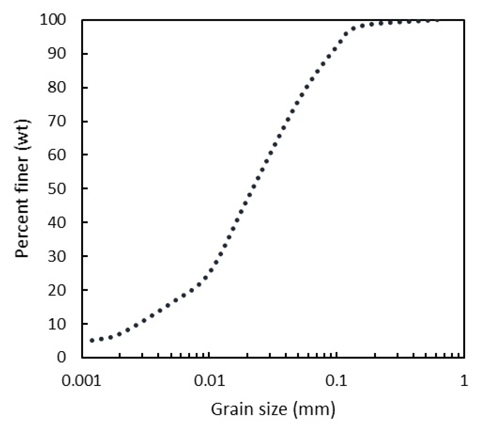
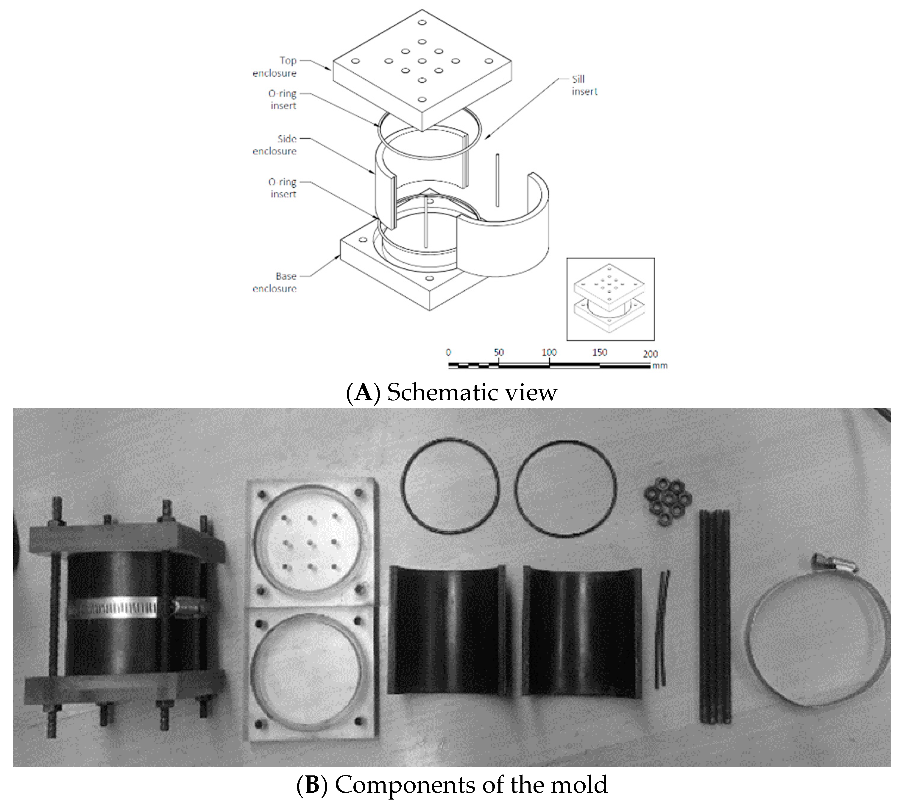
2.1. Sample Preparation

The CPB samples were prepared by mixing tailings, normal Portland cement (NPC), and process water in a stand mixer to obtain a homogeneous mixture. The tailing samples were collected from Barrick’s Williams Mine in Helmo mining camp, Ontario, Canada. The Williams Mine is located in Northwest Ontario, approximately 35 km west of the township Marathon. The ores are predominately amphibolite-facies Archean load gold deposits [21]. The deposits were extracted with a mixture of long hole and Alimak stopes and subsequently backfilled with CPB. The ore is milled to paste consistency with more than 45% passing 0.020 mm as shown in Figure 1 [18,20]. The tailing stream consists of silica, quartz, feldspar, and plagioclase. The sulfides in the tailings can be oxidized to alter the material’s initial gray-to-orange color when exposed to oxygen [22,23]. Table 1 shows the chemical composition of tailing and binder [20].
Studies on the William Mine [17,18,19,20] showed that the mechanical properties of CPB depend upon their physical and chemical characteristics such as the tailings mineralogy, particle size, water content, and binder type etc. Based on their findings, NPC was used to reflect current practice at Williams Mine. The 4.2% and 6.9% binder contents were used to simulate typical mining practice, and the 9.7% binder content was an upper bound and reflects the maximum concentrations used for critical applications such as undercut structures. The samples were prepared with 28% mine water content based on a recent field study which showed mine water content ranged from 26.5% to 29.6% in Williams Mine [18].
Prior to the test, all samples were cast in the cylinders with 72.6 mm diameter and 20 mm height by specially designed four-part spilt molds shown in Figure 2. The mold consisted of top cap, base cap, two-side enclosures, O-ring inserts, and seals. The mold was made of a split acrylonitrile butadiene styrene (ABS) pipe with plexiglass on the top and base caps. The base and the side enclosures were coated with silicone lubricant to facilitate the demolding process. After casting, the percolation holes were taped, and the samples were placed underwater to avoid evaporation.

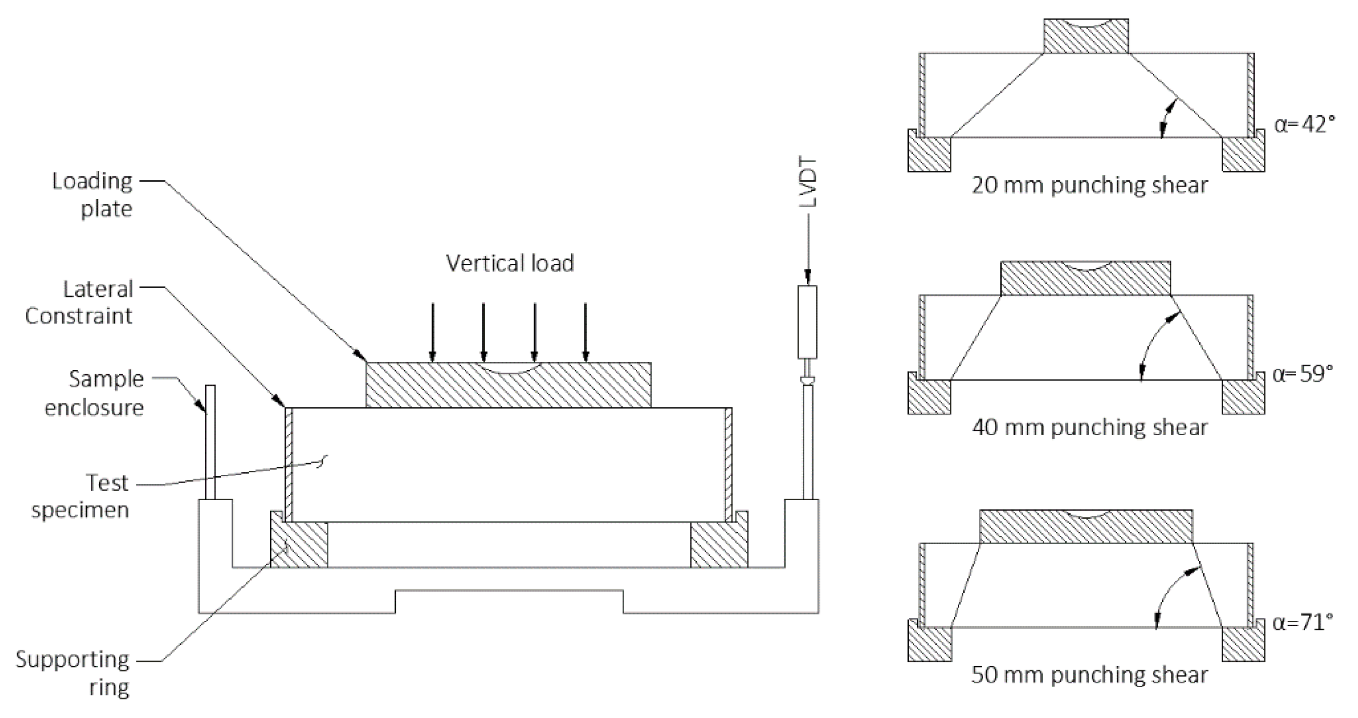
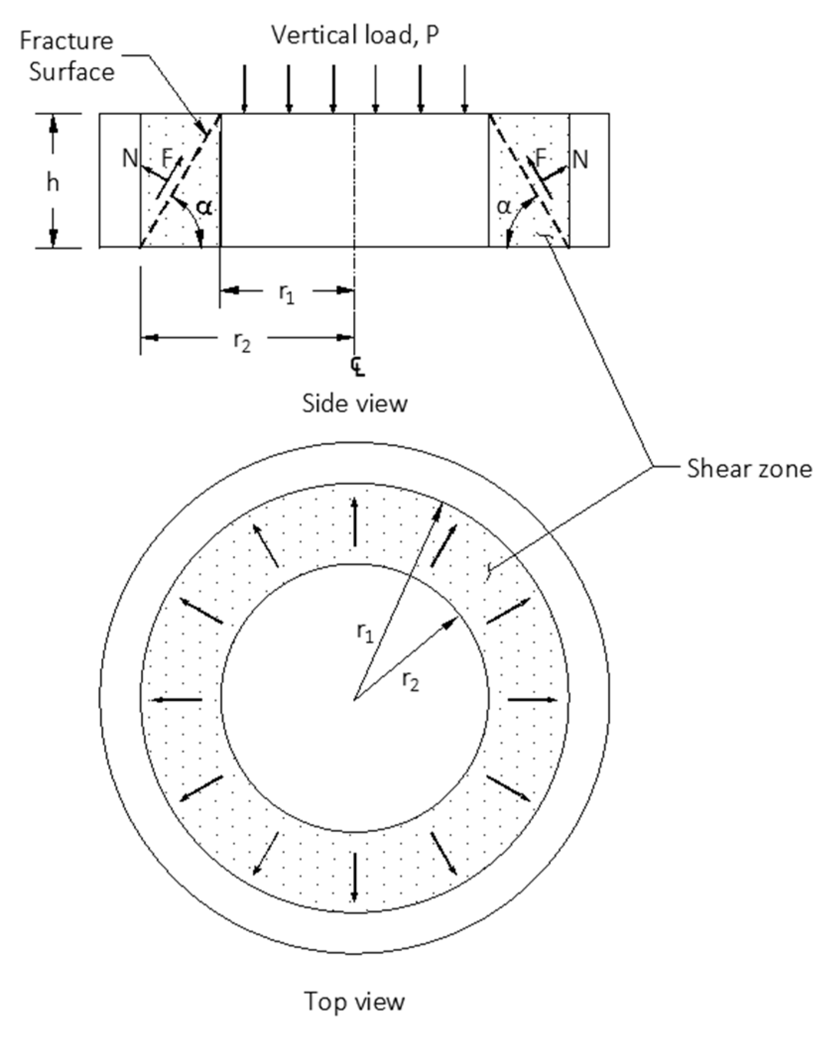
2.2. Testing Methods

We developed a punching shear apparatus for the couple stress test which transfers the compressive stress into a concentrated plane shear. Figure 3 shows a cross-section diagram of the apparatus. The major components consisted of the loading plate, support ring, and lateral conscription ring. The loading plate and support ring were designed to generate a preferential failure surface along the frustum. The lateral conscription ring held the specimen securely inside to provide confining stress so that the extensive shape is not applied to the specimen. Circular loading plates with diameters of 20 mm, 40 mm, and 50 mm were selected in the test, these dimensions enabled us to study the effect of base angle (shown by α in Figure 3), varying from 42° to 71°, on the failure mechanism of CPB under mentioned loading condition.
The vertical load was generated by the Wille Geotechnik Tabletop Electromechanical Apparatus (WGTEA). The vertical pressure from the WGTEA is transferred to the loading plate to generate a shear force and form a failure surface along the frustum. The horizontal deformation is controlled by the lateral conscription ring. The samples were loaded at 0.5 mm/min during the test, the test was performed underwater to reduce the effect of suction. All the testing results were recorded by the computerized data logging system, and the results were analyzed by the software Geosys.
The stress states were defined by the fracture surface upon the ultimate load as demonstrated in Figure 4. The stress states involved two elements: a normal component N that is perpendicular to the fracture surface and a shear component F that is tangent to the fracture surface. The normal stress is determined from the normal component N:
σn = −P(cosα)[(π(r1 + r2) [(r1 − r2)2 + h2]1/2,
While the shear stress is determined from the shear component F:
τ = P(sinα)[(π(r1 + r2) [(r1 − r2)2 + h2 ]1/2,
where P is the ultimate vertical load, α is the angle of the frustum, r1 is the radius of the loading plate, r2 is the radius of the support ring, and h is the height of the disk.

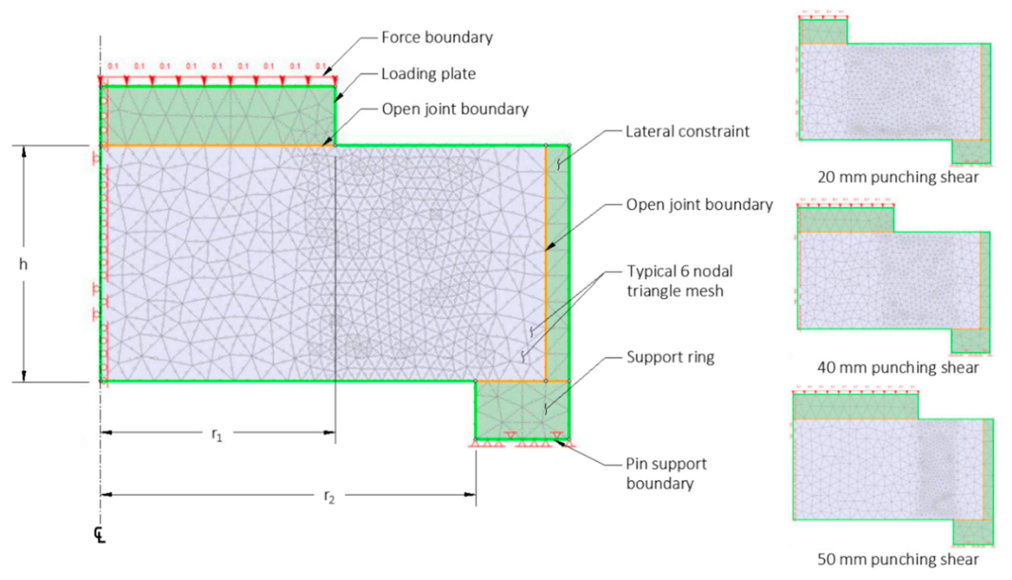
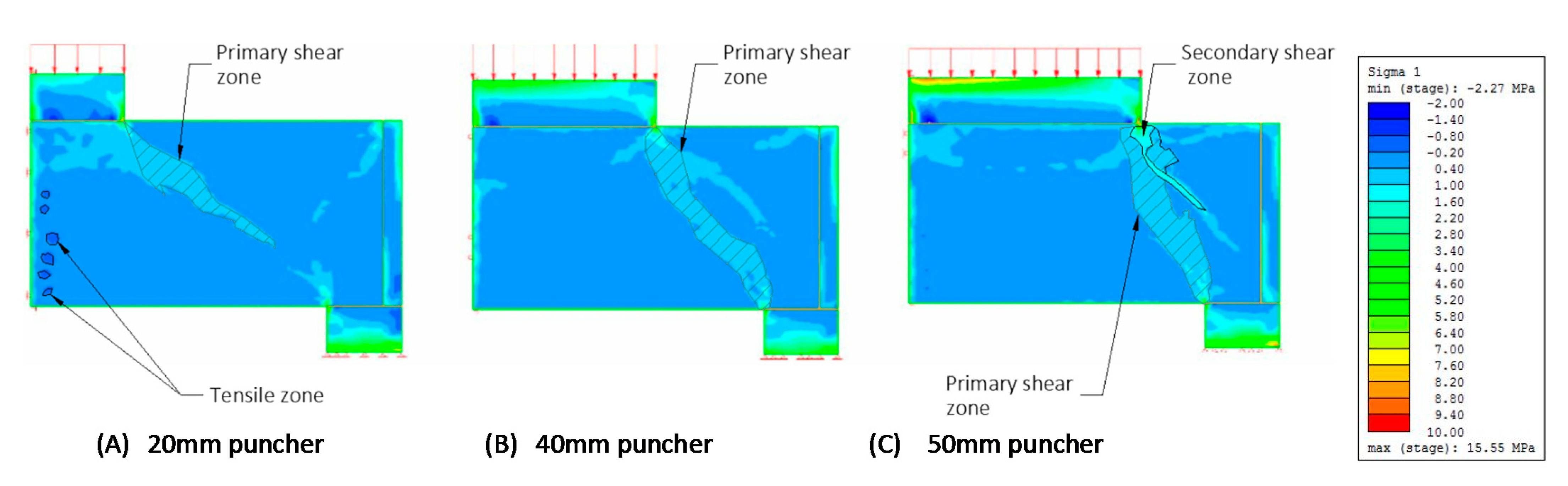
2.3. Numerical Simulation

Since the existing coupled stress testing itself cannot address all the aspects of punching stress transfer mechanisms, a two-dimensional finite element analysis (FEA) was performed for supplementing experimental analysis in providing stress transformation, deformation, and possible failure mechanisms. The numerical simulation was performed by RS2 v9.0 FEA software to determine the stress distribution. The CPB strength parameters were based on direct shear, unconfined compression strength (UCS), and direct tensile tests [6,12,23]. The parameters in the finite element simulations are as follows.
  • The Mohr–Coulomb envelope for the strength parameter [24]
    τp = σ tanϕp + c,
    τr = σ tanϕr,
    where τp is the peak shear stress, τr is the residual shear stress, σ is the normal stress, c is the cohesion, ϕp and ϕr are the peak and the residual angles of frictional resistance, respectively.
  • The modulus of elasticity E (material’s resistance to elastic deformation) [25]
    E = σ/ε,
    where σ is the stress and ε is the strain in the elastic region.
  • The shear modulus (material’s resistance to shear deformation) [25]
    G = τxyxy ≐ Fl/A∆x,
    where G is the shear modulus, τxy is the shear stress, γxy is the engineering shear strain, and l is the gauge length of the shear, F is the total applied force, and A is the area of shear, and ∆x is the lateral displacement.
  • The Poisson’s ratio v (ratio of longitudinal strain to transversal strain) [25]
    v = (E − 2G)/2G,
    where E is the modulus of elasticity and G is the shear modulus.
Figure 5 shows a cross-section diagram of the model. In this model, the elastic-perfect-plastic criterion was employed as strength parameter, and the failure criterion was defined as non-convergence. Considering its geometry, we created a two-dimensional finite element model in which the stress state was analyzed by six-nodal triangle meshes. The mesh density at the shear zone was refined to emphasize the critical state, and the specimen was modeled axisymmetrically around the centerline. Three elements including the loading plate, supporting ring, and the lateral conscription were implemented to replicate the loading conditions. The loading plate was modeled by the force boundary at the top, and the support ring was modeled by the pin-pin boundary at the base. To consider the difference in stiffness, an open joint boundary was designed to allow slippage between the specimen and the attachment.
A total of 36 trials were conducted with the combinations of three cement contents of 4.2%, 6.9%, and 9.7%; and four curing times of 3, 7, 14, and 28 days, each combination was tested three times to assure the repeatability and reproducibility of samples. The configurations are shown in Table 2.

3. Results and Discussion

In this study, hybrid failure results are presented by two types of analysis: (a) the fracture morphology and numerical simulation; and (b) the strength properties. The combination of three cement contents of 4.2%, 6.9%, and 9.7%; and four curing times of 3, 7, 14, and 28 days are presented and compared in each analysis.

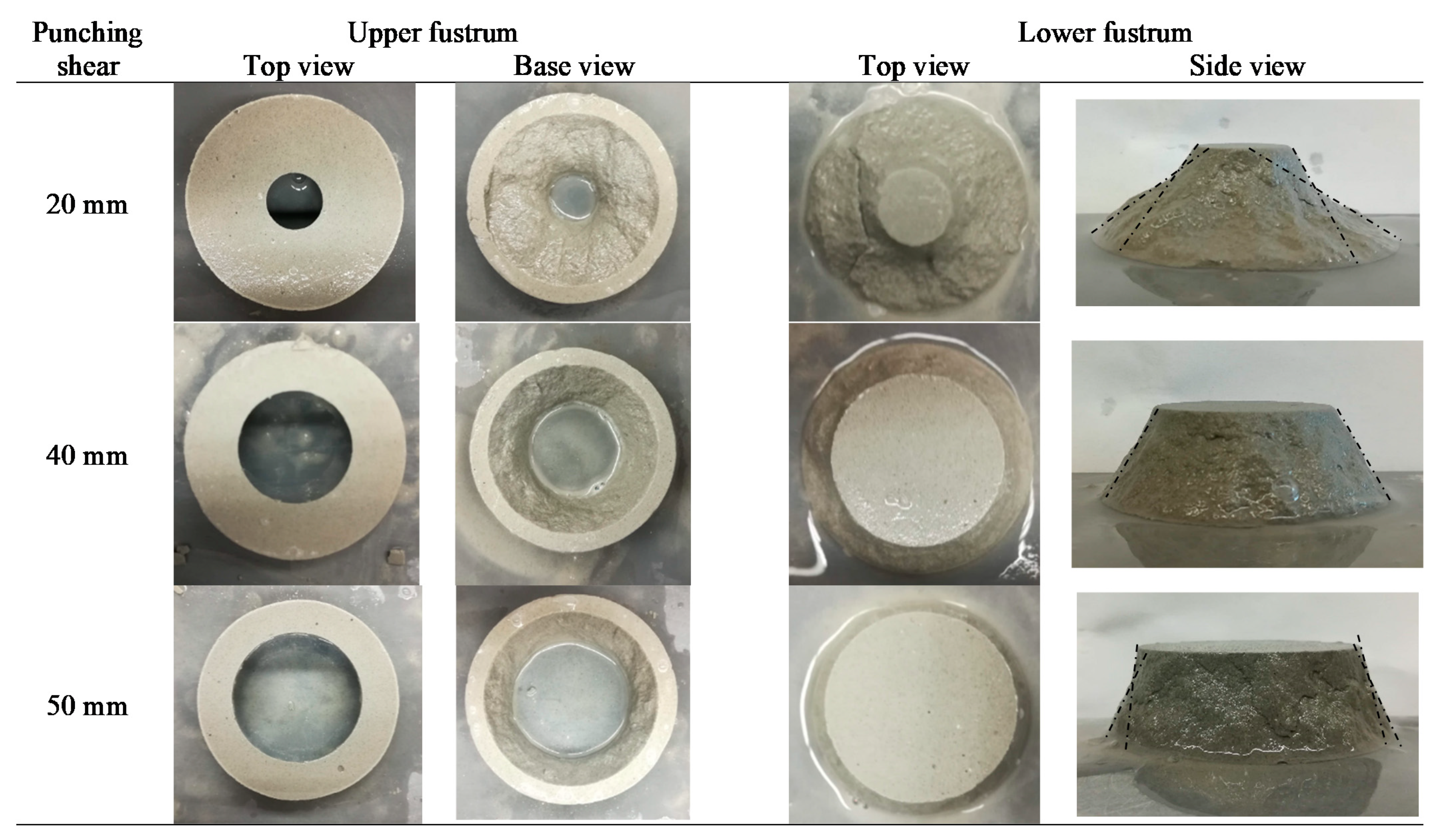
3.1. Fracture Morphology and Numerical Simulation

Figure 6 shows the typical fracture surfaces of the 20 mm, 40 mm, and 50 mm diameters of puncher plates. Under the critical local stress, the CPB samples cannot carry the load and a fracture occurs. In all the cases, the failure surfaces were characterized by a conic fracture from the loading plate to the support ring. The specimen was divided into two intact fragments, a conical central part and a cylindrical external part.
The fracture morphologies of the 40 mm and 50 mm puncher plates were similar, but different from that of the 20 mm. The fractures of the 40 mm and 50 mm punching plates were characterized by predefined failure planes that follow the angle α, of 59° for 40 mm and 71° for 50 mm plates. The frustum with the 40 mm plate remained intact, while the frustum with the 50 mm plate exhibited secondary cracks, despite the radial reinforcement. By comparison, the fracture of the 20 mm punching plate did not follow the predefined failure surface, it was characterized by a curved surface which was not possible for the continuous shear transfer across the failure plane. This failure occurred in the bending of the central part of the specimen which simultaneously created fissures at the base of the specimen.
The results of numerical simulation were consistent with those of the fracture morphology as shown in Figure 7. Upon the punch simulation stress initiated under the loading plate; further increasing loads led to the development of stress along the failure envelope. The results showed that the viability of the hybrid failure depend on the aspect ratio. The stress at a relatively small aspect ratio 42° of the 20 mm puncher plates exhibited a tensile zone around the center of the sample at the beginning and then led to the formation of the bending moment resulting in flexure failure, which indicated the development of tensile stress. The stress at an aspect ratio 59° of the 40 mm plate was well defined as the strain flow across the failure surface. By contrast, the stress at a relatively large angle 71° of the 50 mm confinement led to the development of a secondary stress concentration. This assumption was consistent with the visual observations of the CPB fracture surfaces in which the size of the punching plate was inversely proportional to the bending stiffness of the central part of the specimen, while the angle of the shear plane directly influenced the hybrid failure of the specimen. Our result was consistent with the statement by Boulifa et al. (2013) in concrete [14]. Our studies showed that FEA was an assessment tool, it provided insight into punching shear failure and crack formation, which cannot be obtained through experimental investigations.

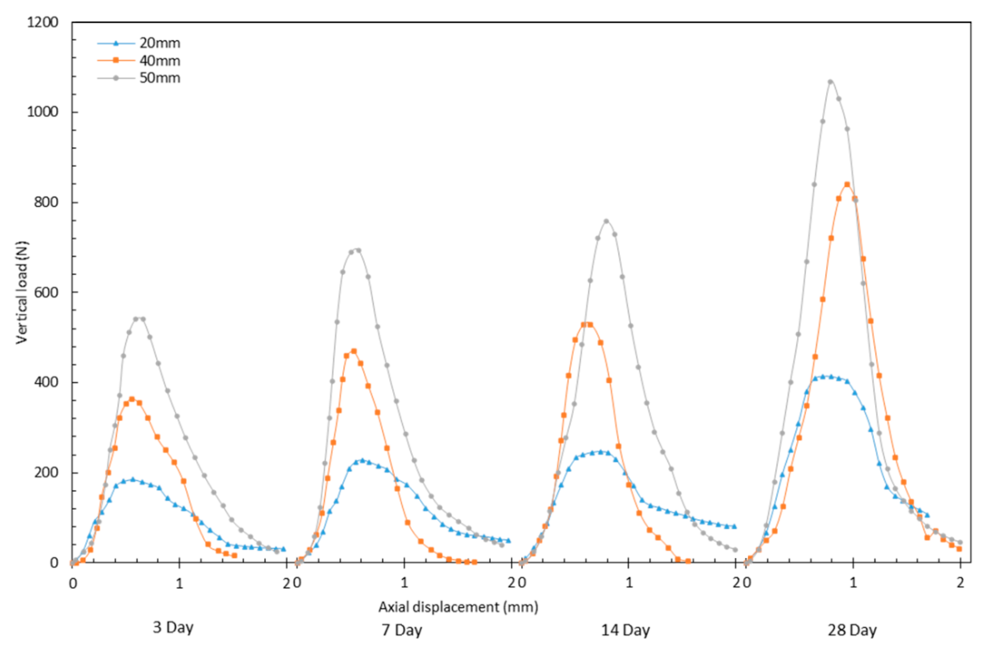
3.2. Strength Properties

The failure strengths of CPB under the 20 mm, 40 mm, and 50 mm punching plates at 9.7% binder contents with 3, 7, 14, and 28 days curing times are presented in Figure 8 for comparison. It can be seen that the load-displacement behavior of punching shear has three phases: an initial elastic behavior, a plateau region with peak strength around 0.6–0.8 mm displacement, and a post-peak behavior from onward. The phenomenon can be attributed to the propagation of cracks generated in the pre-peak and peak regions. Regardless of the binder contents and curing time, the post-peak behaviors of the 40 mm and 50 mm plates were different from that of the 20 mm, which was characterized by a brittle response. By contrast, the post-peak behavior of the 20 mm plate was characterized by a less brittle behavior, the reason for this was the failure mechanism transitions from shear to flexural with angles decreases. Indeed, the less brittleness is indicative of flexure failure; and more brittle behavior is indicative of shear failure. This was consistent with the analysis of the fracture morphology and the numerical simulation.
As expected, the CPB strength increased with the curing time and the binder contents. This influence was illustrated by the fact that the failure strength increases successively from 4.2% to 9.7% binder contents and from 3 to 28 days curing times, respectively, despite slight variations of the data due to each trial’s uncertainties and experimental variations from sample to sample. Regardless of the failure types, either shear or tensile, higher binder contents and more curing time generated more strength, the reason for this was the increase in the degree of hydration with time and binder contents. In fact, when the curing time and the binder contents of the CPB increased, CPB hardened due to the progression of binder hydration. This hardening resulted in an increased value of the critical stress to break the sample. The result was consistent with the studies of direct shear by Nasir and Fall (2008), and Koupouli et al. (2016), and the tensile by Pan and Grabinsky (2021) in which the shear strengths were related to the binder content and the curing time [4,5,12].
Several mechanisms are account for the failure mechanism of CPB under stress. Shear, tensile, and the combination of tensile and shear are of three basic failure types [9]. In practice, a pure tensile or shear stress is too ideal while in most situations the area surrounding the object is subject to a couple of shear and tensile stresses. For example, the extraction of the adjacent stopes and the undercut usually introduces differential stresses, subsequently results in the combination of shear and tensile failures. The coupled stress in our study is neither an intrinsic shear nor pure tensile stress. It is a combination of tensile and shear strength in the function of the angle of the frustum. Our design provides a simple means for determining the hybrid failure strength of CPB. The testing arrangements are both practical and reliable, as well as rigorous from a mechanics point of view.

4. Conclusions

We developed a new punching shear apparatus to evaluate the shear and tensile behavior of CPB in this study. We focused on the applications and a closer examination of the hybrid failure through both laboratory fracture morphology and numerical simulation. A series of FEA were performed to obtain a suitable specimen geometry which provided unidirectional coupled stresses under tensile and shear stresses on the same specimen. We observed that fracture morphology is strongly related to the angle of the frustum, which is consistent with the numerical simulation. We substantiated that the FEA is essential in providing stress transformation, deformation, possible failure mechanisms, and supplement experimental observations. Our study evaluated hybrid failure strength at the effects of different cement binder content and curing time. The hybrid failure strength was determined from the punching shear apparatus, the device was the most fundamental component in our study. Our results showed that the curing time and the binder content-dependent nature of the CPB significantly affect the strength properties in all the tests. This work provides a benchmark for others to test their materials and establish the appropriate failure envelope for their CPB designs under low confining stress conditions.

Author Contributions

Conceptualization, A.P. and M.G.; methodology, A.P.; software, A.P.; validation, A.P., M.G., M.J., and L.G.; formal analysis, A.P.; investigation, A.P.; resources, M.G.; data curation, A.P.; writing—original draft preparation, A.P.; writing—review and editing, A.P., M.G., M.J., and L.G.; visualization, A.P.; supervision, M.G.; project administration, A.P.; funding acquisition, M.G. All authors have read and agreed to the published version of the manuscript.

Funding

This study was funded in part by National Science and Engineering Research Council (NSERC) of Canada, University of Toronto, and the industrial funding from the Barrick Gold Corporation.

Data Availability Statement

All data, models, or code that support the findings of this study are available from the corresponding author upon reasonable request.

Acknowledgments

The authors would like to acknowledge the William’s Operation for providing tailings, binders, and process water. We would also like to thank Xiaoyu Song from Portland State University, USA for his technical support.

Conflicts of Interest

The authors declare no conflict of interest. The funders had no role in the design of the study; in the collection, analyses, or interpretation of data; in the writing of the manuscript, or in the decision to publish the results.

References

  1. Hassani, F.; Archibald, J. Mine Backfill; Canadian Institute of Mining, Metallurgy and Petroleum: Montreal, QC, Canada, 1998. [Google Scholar]
  2. Grabinsky, M.W.F.; Simms, P. Self-Desiccation of Cemented Paste Backfill and Implications for Mine Design. In Proceedings of the Ninth International Seminar on Paste and Thickened Tailings, Perth, Australia, 3–7 April 2006; Australian Centre for Geomechanics: Perth, Australia, 2006; pp. 323–332. [Google Scholar] [CrossRef]
  3. Grabinsky, M.W.F.; Simms, P. Direct measurement of matric suction in triaxial tests on early age cemented. Can. Geotech. J. 2009, 46, 93–101. [Google Scholar] [CrossRef]
  4. Nasir, O.; Fall, M. Shear behaviour of cemented pastefill-rock interfaces. Eng. Geol. 2008, 101, 146–153. [Google Scholar] [CrossRef]
  5. Koupouli, N.J.; Belem, T.; Rivard, P.; Effenguet, H. Direct shear tests on cemented paste backfill–rock wall and cemented paste backfill–backfill interfaces. J. Rock Mech. Geotech. Eng. 2016, 8, 472–479. [Google Scholar] [CrossRef] [Green Version]
  6. Pan, A.N.; Grabinsky, M.W.F.; Guo, L. Shear Properties of Cemented Paste Backfill under Low Confining Stress. Adv. Civ. Eng. 2021, 2021, 1–11. [Google Scholar] [CrossRef]
  7. Fall, M.; Belem, T.; Samb, S.; Benzaazoua, M. Experimental characterization of the stress—strain behaviour. J. Mater. Sci. 2007, 42, 3914–3922. [Google Scholar] [CrossRef]
  8. Liu, Q.; Liu, D.; Tian, Y.; Liu, X. Numerical simulation of stress-strain behaviour of cemented paste backfill in triaxial compression. Eng. Geol. 2017, 231, 165–175. [Google Scholar] [CrossRef]
  9. Zeng, B.; Huang, D.; Ye, S.; Chen, F.; Zhu, T.; Tu, Y. Triaxial extension tests on sandstone using a simple auxiliary apparatus. Int. J. Rock Mech. Min. Sci. Geomech. 2019, 120, 29–40. [Google Scholar] [CrossRef]
  10. Jafari, M.; Shahsavari, M.; Grabinsky, M. Drained Triaxial Compressive Shear Response of Cemented Paste Backfill (CPB). Rock Mech. Rock Eng. 2021, 54, 3309–3325. [Google Scholar] [CrossRef]
  11. Johnson, J.C.; Seymour, J.B.; Martin, L.A.; Stepan, M.; Arkoosh, A. Strength and Elastic Properties of Paste Backfill at the Lucky Friday Mine, Mullan, Idaho. In U.S. Rock Mechanics/Geomechanics Symposium; American Rock Mechanics Association: San Francisco, CA, USA, 2015. [Google Scholar]
  12. Pan, A.N.; Grabinsky, M. Tensile Strength of Cemented Paste Backfill. Geotech. Test. J. 2021, 44, 1886–1897. [Google Scholar] [CrossRef]
  13. Komurlu, E.; Kesimal, A.; Demir, S. Experimental and numerical analyses on determination of indirect (splitting) tensile strength of cemented paste backfill materials under different loading apparatus. Geomech. Eng. 2016, 10, 775–791. [Google Scholar] [CrossRef]
  14. Boulifa, R.; Samai, L.M.; Benhassine, T.M. A new technique for studying the behaviour of concrete in shear. J. King Saud Univ. Sci. 2013, 25, 149–159. [Google Scholar] [CrossRef] [Green Version]
  15. Francesconi, L.; Pani, L.; Stochino, F. Punching shear strength of reinforced recycled concrete slabs. Constr. Build Mater. 2016, 127, 248–263. [Google Scholar] [CrossRef]
  16. Genikomsou, A.S.; Polak, A.M. Finite element analysis of punching shear of concrete slabs using damaged plasticity model in ABAQUS. Eng. Struct. 2015, 98, 38–48. [Google Scholar] [CrossRef]
  17. Grabinsky, M.W.F. In situ monitoring for ground truthing paste backfill designs. In Proceedings of the Thirteenth International Seminar on Paste and Thickened Tailings, Toronto, ON, Canada, 3–6 May 2010; Australian Centre for Geomechanics: Toronto, ON, Canada, 2010; pp. 85–98. [Google Scholar] [CrossRef] [Green Version]
  18. Jafari, M.; Shahsavari, M.; Grabinsky, M.W.F. Cemented Paste Backfill 1-D Consolidation Results Interpreted in the Context of Ground Reaction Curves. Rock Mech. Rock Eng. 2020, 53, 4299–4308. [Google Scholar] [CrossRef]
  19. Thompson, B.D.; Bawden, W.F.; Grabinsky, M.W.F. In situ measurements of cemented paste backfill at the Cayeli Mine. Can. Geotech. J. 2012, 49, 755–772. [Google Scholar] [CrossRef]
  20. Jafari, M.; Shahsavari, M.; Grabinsky, M.W.F. Hydration Effects on Specific Gravity and Void Ratio of Cemented Paste Backfill. Geotech. Test. J. 2020, 43, 1300–1316. [Google Scholar] [CrossRef]
  21. Barrick Gold Corporation. Roscoe Postle Associates, Technical Report on the Hemlo Mine; Barrick Gold Corporation: Marathon, ON, Canada, 2017. [Google Scholar]
  22. Ercikdi, B.; Kesimal, A.; Cihangir, F.; Deveci, H.; Alp, I. Cemented paste backfill of sulphide-rich tailings: Importance of binder type and dosage. Cem. Concr. Compos. 2009, 31, 268–274. [Google Scholar] [CrossRef]
  23. Grabinsky, M.W.F.; Pan, A.N. Cemented paste backfill failure envelope at low confining stress. In Proceedings of the Minefill 2021, The 13th International Symposium on Mining with Backfill, Katowice, Poland, 25–28 May 2021; Society for Mining, Metallurgy and Exploration Minefill: Katowice, Poland, 2021. [Google Scholar]
  24. Terzaghi, K. Theoretical Soil Mechanics; John Wiley & Sons, Inc.: Hoboken, NJ, USA, 1943. [Google Scholar]
  25. Beer, F.P.; Johnston, E.R.; DeWolf, J.T.; Mazurek, D.F. Mechanics of Materials, 6th ed.; McGraw Hill: New York, NY, USA, 2012. [Google Scholar]
Figure 1. Grain size distribution.
Minerals 11 01141 g001
Figure 2. Punching shear sample mold.
Minerals 11 01141 g002
Figure 3. Cross-section diagram of punching shear apparatus.
Minerals 11 01141 g003
Figure 4. Schematic fracture surface at the ultimate load.
Minerals 11 01141 g004
Figure 5. The two-dimensional finite element analysis (FEA) model.
Minerals 11 01141 g005
Figure 6. Typical fracture morphology of the 20, 40, and 50 mm diameters of the puncher plates.
Minerals 11 01141 g006
Figure 7. Punching shear numerical simulation.
Minerals 11 01141 g007
Figure 8. Load displacement curve of 9.7% CPB.
Minerals 11 01141 g008
Table 1. Minerology and composition.
Tailing Composition
CompositionCaOSiO2SO3Al2O3MgOFe2O3K2ONa2O
Content (wt %)64.220.04.13.93.13.00.50.2
Binder Composition
Composition SiO2Al2O3CaOMgOK2ONa2OFe2O3STiO2P2O5
Content (wt %)59.812.23.63.53.43.22.40.60.40.2
Table 2. Punching shear test configuration.
Cement Content (%)Binder TypeCuring Time (Days)Trial Per MixNumber of Samples
4.2100% GPC3, 7, 14 and 28312
6.9100% GPC3, 7, 14 and 28312
9.7100% GPC3, 7, 14 and 28312
Publisher’s Note: MDPI stays neutral with regard to jurisdictional claims in published maps and institutional affiliations.

