Technical Note

Valorization of Kimberlite Tailings by Carbon Capture and Utilization (CCU) Method

School of Engineering, University of Guelph, 50 Stone Rd. E, Guelph, ON N1G 2W1, Canada
*
Author to whom correspondence should be addressed.
Minerals 2020, 10(7), 611; https://doi.org/10.3390/min10070611
Submission received: 5 June 2020 / Revised: 3 July 2020 / Accepted: 6 July 2020 / Published: 8 July 2020
(This article belongs to the Special Issue Reutilization and Valorization of Mine Waste)

Abstract

:
In the world of construction, cement plays a vital role, but despite its reputation and affordable prices, the cement industry faces multiple challenges due to pollution and sustainability concerns. This study aimed to assess the possibility of utilizing carbonated kimberlite tailings, a waste product from diamond mining, as a partial cement substitute in the preparation of concrete bricks. This is a unique opportunity to help close the gap between fundamental research in mineral carbonation and its industrial implementation to generate commercial products. Kimberlite was subjected to a mild thin-film carbonation process in a CO2 incubator at varying levels of CO2 concentration (10 vol% and 20 vol% at ambient pressure), kimberlite paste moisture content (10 wt% to 20 wt%), and chamber temperature (35 and 50 °C). The formation of magnesium carbonates, in the form of nesquehonite and lansfordite, was verified by X-ray diffraction analysis, and total CO2 uptake was quantified by thermal decomposition in furnace testing. Carbonated kimberlite tailings were then used to cast bricks. Replacement of cement between 10% and 20% were tested, with a constant water-to-binder ratio of 0.6:1, and a cementitious material-to-sand ratio of 1:3. Initial water absorption and 7- and 28-days compressive strength tests were carried out. The results obtained confirm the possibility of using carbonated kimberlite to replace cement partially, and highlight the benefits of carbonating the kimberlite for such application, and recommendations for future research are suggested. This study demonstrates the potential use of mining tailings to prototype the sequestration of CO2 into sustainable building materials to positively impact the increasing demand for cement-based products.

1. Introduction

A contemporary life without cement has been unimaginable for centuries. Cement is a primary building element for infrastructure development and housing, and a gateway to economic growth. The cement industry performs an essential function in advancing living standards worldwide by generating numerous indirect and direct jobs, consequently affording the associated industry with varied economic gains in cascade. Although it has many advantages such as practicality, it is responsible for 8% of global CO2 emissions. The global cement industry has produced about 2.2 billion tonnes of CO2, and the calcination process accounts for more than half of that amount. Moreover, the third biggest national emitter after China and the United States of America would be the world cement industry [1]. The consumption of cement or other industrial binders raises greenhouse gas emissions because a typical cement plant generates embedded discharges of 0.95 kg CO2 kg−1 of cement [2]. This unwanted reality will continue for decades to come until a more sustainable alternative is developed.
The global atmospheric temperature is shifting faster now than at any point in modern history, and ways to reduce greenhouse gases in the atmosphere are therefore one of our priorities to fight this climate change [1]. Recent studies and research have focused on the recovery of waste from various industrial sectors that can replace cement up to a certain quantity without compromising strength and durability [2]. When focusing on the mining sector, tailings are equivalent to approximately 99% of the total mineral excavated, while only 1 to 3% is concentrated [3]. These tailings are assessed on a scale of billions of tonnes per year regarding waste material, which is a huge sum that causes expensive landfills [4]. In many countries, rapid urbanization has also produced a large quantity of waste that impacts the environment [2]. With the rising demand for industrial waste and housing, it is advantageous to use this waste as a building resource in concrete and brick production [5]. Production of firebricks is a process that is highly energy intensive, and thus contains high embodied energy and carbon footprint [6]. The reduction of CO2 emissions in half was imposed by the “Cement and Technology Roadmap 2009” as a worldwide challenge to be accomplished by 2050 [7]. The increase in demand for cement focuses a lot on finding a better replacement for it. The emphasis on waste recovery has two main reasons: (1) it is inexpensive; and (2) it reduces discharges. A key factor in mineral carbonation is the availability of an abundant source of carbon dioxide, making the construction industry its best host.
Several studies have taken place on the utilization of various waste materials as a component for casting bricks; examples of such waste materials include wastewater sludge [8,9,10], pharmaceutical waste [11], paper and pulp mill residue [12], municipal solid waste [13], olive industry waste [14,15,16,17], and tea waste from processing plants [18], among many others. Research on the utilization of waste materials from steelmaking processes such as stainless-steel slag [19] and Basic Oxygen Furface slag [20] has been considered in the context of CO2 sequestration due to their suitable mineral composition that is reactive with CO2 to form carbonates; such carbonated slags have then been considered to be valorized in the field of construction. Through the Carmex Project [21], processed kimberlite has been identified as appropriate for carbon capture given the high level of mineral carbonation obtained in small aqueous reaction scale and based on extensive life cycle analysis of possible scenarios. Kimberlite is a magnesium- and calcium-rich silicate mineral and is presently stored in tailings ponds due to the remote location of mining operations such as those of De Beers Canada in the Northwest Territories. Using kimberlite for CO2 sequestration and for utilization in building materials thus presents an opportunity to better deal with this waste material, and to also encourage diamond mining from reserves that are not currently economically viable.
Accelerated mineral carbonation has been practiced for years, and its use for carbon capture and storage (CCS) is discussed widely in various research areas [22]. Consumers and industries are already turning toward strategies for combating climate change and adding value to their products via carbon capture and utilization (CCU) technologies. Adding value to commodities through substituting traditional methods for CCU also improves commercial efficiency, together with increasing the environmental advantages of mineralization [23]. Accelerated mineral carbonation processes are energy demanding, and efforts have been made to intensify the reactions, which often require high pressure and temperatures [24], along with pre-treatment of the minerals [25,26] and other reaction additives [27]. Thin-film carbonation, under mild conditions, is a form of accelerated carbonation that results in a moderate carbonation extent, but with low energy consumption [19].
This study presents the properties of processed kimberlite, sourced from a diamond mining operation, before and after being reacted with CO2 in an artificially accelerated mineral carbonation process, and focuses on its use in construction materials such as concrete bricks. The article assesses the influence of the replacement ratio of the kimberlite, and the carbonation conditions the kimberlite was subjected to (%CO2, moisture content, and temperature), on the physico-mechanical properties of the bricks (initial water absorption, compressive strength, and stress strain behavior, after 7 and 28 days of curing). The study outcomes indicate the potential of treated kimberlite in brick-making for a more sustainable masonry alternative in the construction sector.

2. Materials and Methods
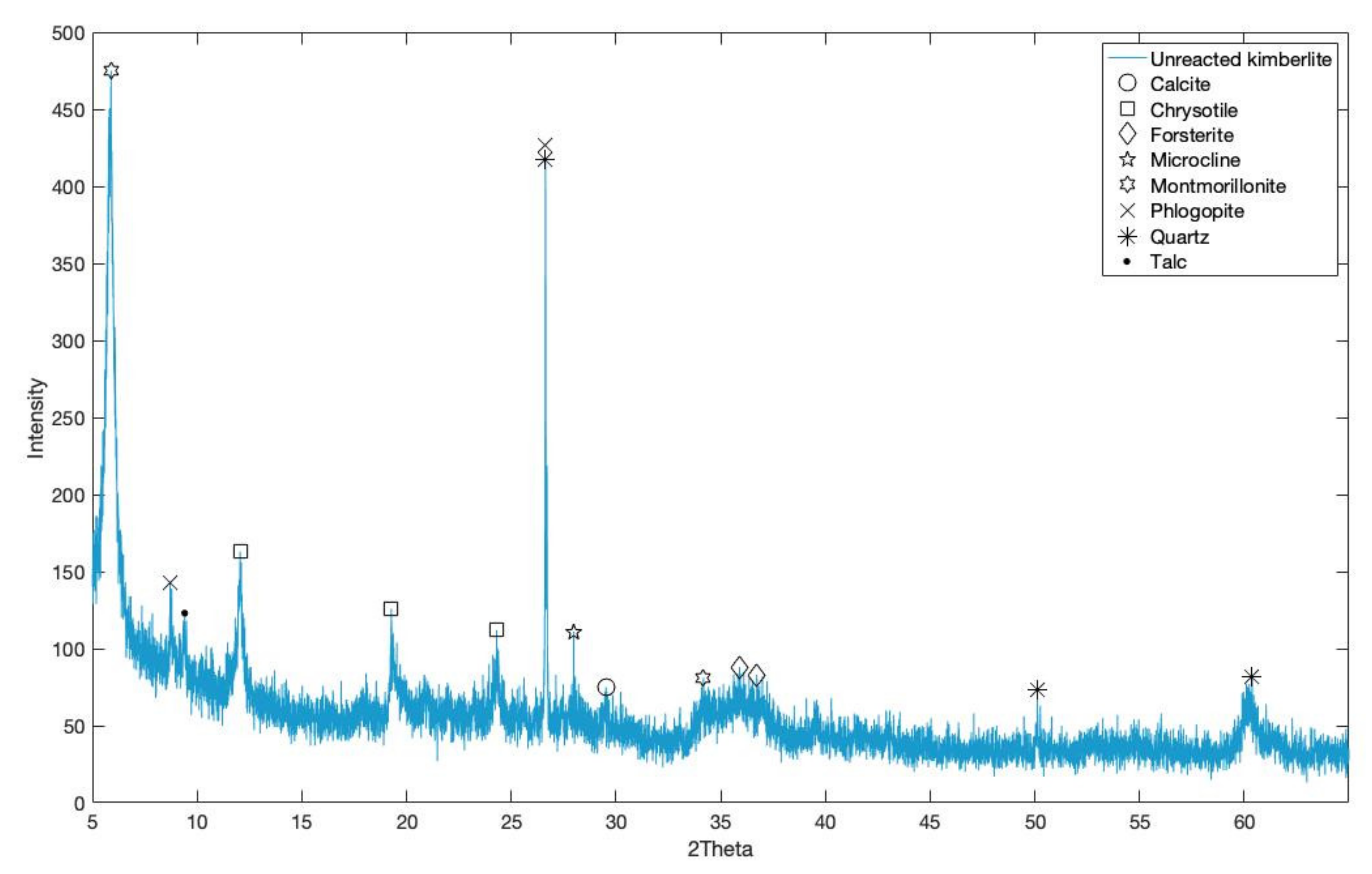
2.1. Kimberlite

Kimberlite was sourced from Gahcho Kué Diamond Mine, Northwest Territories, Canada, owned by the De Beers Group. The kimberlite received was freshly collected on site, wet, and was classified as fine processed kimberlite (FPK) with a grain size ranging from 3.9 to 62.5 µm. For the carbonation experiment, it was dried in an oven at 50 °C for 24 h and ground by a pestle to attain a powdery form. The elemental composition of the kimberlite was 48.4% SiO2, 27.5% MgO, 9.42% Fe2O3, 6.77% Al2O3, 3.0% CaO, 1.79% K2O, 0.91% P2O2, and 0.584% Na2O, determined by wavelength dispersive X-ray fluorescence (WDXRF, Malvern Panalytical, Malvern, United Kingdom).
The X-ray diffraction (XRD) diffractogram of the unreacted kimberlite is presented in Figure 1. According to the XRD analysis, unreacted kimberlite is mainly composed of, in alphabetic order, calcite (CaCO3), chrysotile (Mg3Si2H4O9), forsterite (Mg2SiO4), microcline (KAlSi3O8), montmorillonite ((Na,Ca)0.3(Al,Mg)2Si4O10(OH)2·nH2O), phlogopite (KMg3(AlSi3O10)(OH)2), quartz (SiO2), and talc (Mg3Si4O10(OH)2). This composition is in agreement with the characterization done by Mervine et al. [28] on processed kimberlite from Gahcho Kué. Its volatile content, determined by furnace loss on ignition (LOI) at 950 °C, was 7.12 wt%; such volatiles are attributable mainly to pre-existing carbonates, hydrated silicates, and metal hydroxides. After heat treatment to remove thermally decomposable hydrates and hydroxides, the LOI was reduced to 4.32 wt%, which is attributable to its CO2 content.

2.2. Thin-Film Carbonation

For thin-film carbonation, a CO2 incubator (Binder C170, Tuttlingen, Germany) was used. Experimental procedures and conditions were adapted from Bodor et al. [29] and Santos et al. [19]. Reaction temperatures of 35 and 50 °C, CO2 levels of 10 and 20%, and moisture contents of 10, 15, and 20 wt% were tested. In three stainless steel trays, 60 g of kimberlite was wetted using ultrapure water (18.2 MΩ·cm) to attain moisture contents of 10, 15, and 20 wt% for each sample. Around 50 g of kimberlite was spread on the bottom of the trays to make a thin layer, and 10 g was put in a small crucible. The trays and crucibles were put into a CO2 incubator for 144 h. Every 24 h, the small crucible that contained 10 g of wet kimberlite was put in an oven (60 °C) for 2–3 h to calculate the loss in moisture content during the 24 h in the incubator and subsequently determine the amount of ultrapure water required to add to the trays to maintain their initial moisture content. It is important to check their moisture content at least once in every 24 h because the heat produced during the exothermic mineral carbonation process can increase the chances of the samples drying out [30]. At the same time, the content that remained in each tray was lightly deagglomerated by using a pestle to increase its surface area (area of reactivity) as carbonation can lead to cementitious behavior of the stationary material, which decreases powder surface area and hinders the carbonation progression [31]. Once the content in the tray was rewetted to its initial moisture content, it was put back in the CO2 incubator for another 24 h. The same steps were repeated until the total amount of time that each tray spent in the incubator reached 144 h.
Mineral carbonation is not widely practiced due to process limitations including high energy intensity, low reaction conversion, and slow reaction kinetics [32]. Hence, a mild carbonation treatment was utilized in this study, despite its reduced ability in sequestering CO2. The rationale is that it is more feasible to reach lower carbonation conversion with less energy expenditure than to aim for high carbonation conversions but with much higher energy demand, which reduces the net CO2 sequestration achievable.
The carbonated kimberlite samples were mineralogically examined through the furnace test and XRD analysis. The furnace test was conducted with the samples’ weights measured at two temperatures, 300 °C and 950 °C. The weight loss up to 300 °C is attributable to chemically bonded water (hydrates and hydroxides), some of which may have formed during carbonation, and the weight loss between 300 °C and 950 °C is attributable to CO2 released from Ca- and Mg-carbonates.

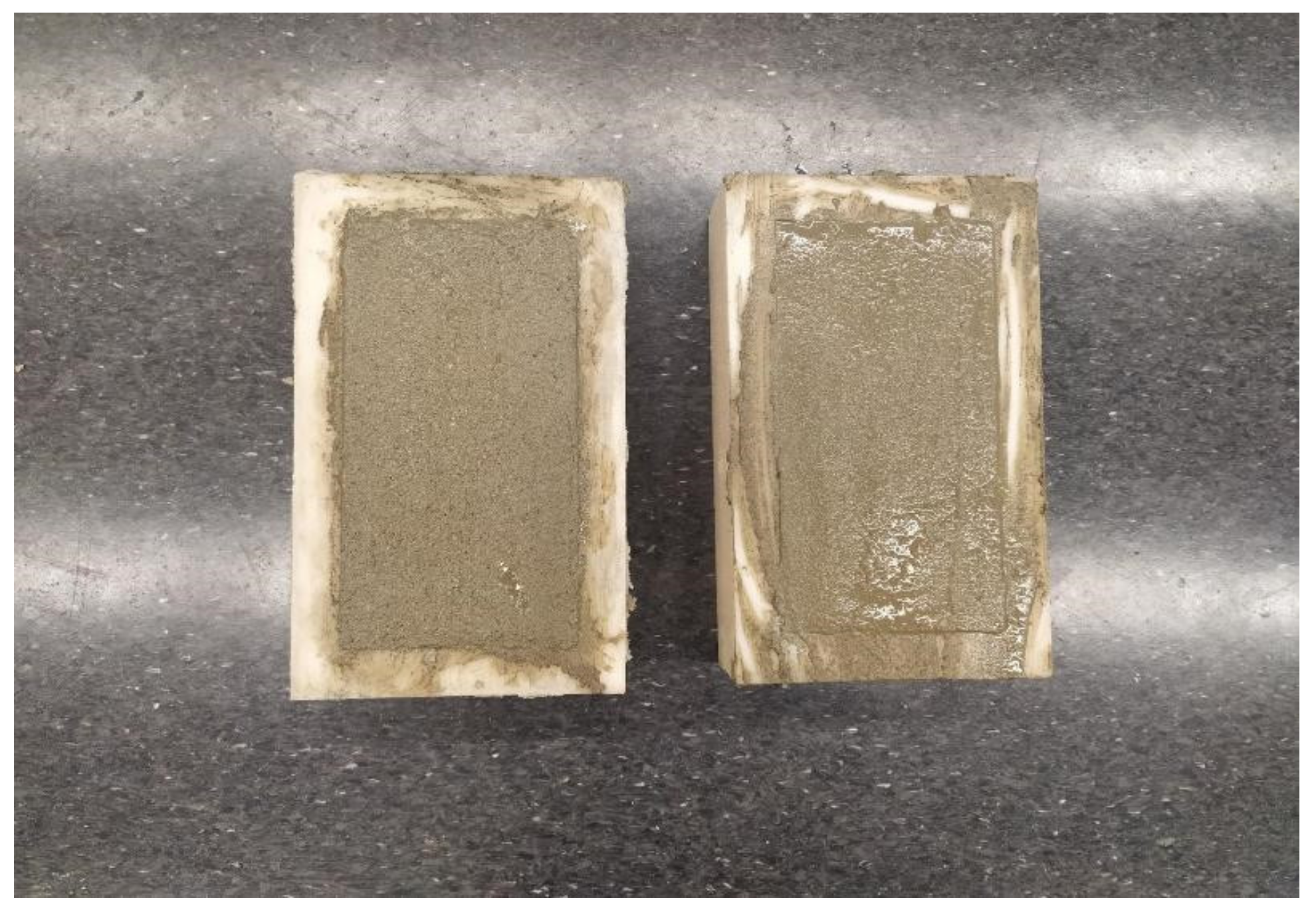
2.3. Casting of Bricks

The samples collected after 144 h from the incubator were used as a replacement for cement in concrete brick making. The samples were stored in separate containers. The various alterations in the experiments were used to create 12 different levels of carbonated kimberlite. These samples were used to cast bricks and compared with a control brick (industrial standard) according to ASTM standards [33].
The mix design of the concrete brick determines its strength. The ratio of cementitious material to sand was fixed as 1:3 and the water-to-cement ratio was 0.6:1 to produce industrial standard bricks. The kimberlite was used as a 10% replacement of cement in our testing. The main constituents used for casting a concrete brick were 600 g of cement and kimberlite as the binding material (540 g cement and 60 g of kimberlite), 1800 g of sand as its aggregate (to fill the voids and increase the density of the brick), and 360 mL of water for the chemical reaction in the mixture. The quantities were carefully measured using a weight balance and mixed together in a container to obtain a plastic mix. The components were mixed together with the help of a hand mixer. The brick mold was coated with grease and the mixture was filled in three steps with uniform compaction, as shown in Figure 2. The brick dimension was 20 cm (length) × 10 cm (width) × 6 cm (height). The molded bricks were placed to set/dry in the CO2 incubator at 35 °C and 10% CO2 for 24 h, allowing for CO2 dissolution into porewater and some early strength-producing carbonation to occur prior to pore drying. The set, dried bricks were then demolded, weighed on a weighing balance, and numbered as specified in Table 1.
For comparison to the industrial standard, two cement bricks were cast and named as control 1 and control 2. Additionally, control bricks were cast with unreacted kimberlite as 10% and 20% replacement to cement, namely control 10 and control 20, respectively.

2.4. Initial Water Absorption Test

The initial weights of the demolded bricks were noted as W1. Then, the bricks were immersed in water for curing, as shown in Figure 3. The time of immersion was noted, and the brick was removed from water after 24 h. The brick was set to air dry, and the surface of the brick was wiped with a cloth to remove any moisture and water from the brick surface. Then, the brick was weighed again in the weighing balance as W2. The gain in weight was calculated by Equation (1) to give the initial water absorption capacity of the brick. Bricks were then returned to water for immersion curing for another six or 27 days, according to Table 1.
Initial water absorption capacity of brick (%) = {(W2 − W1) × 100/W1}

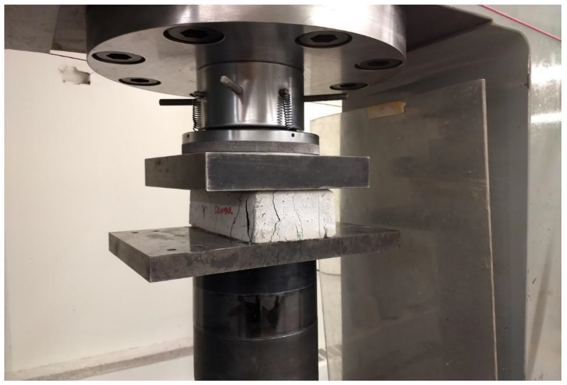
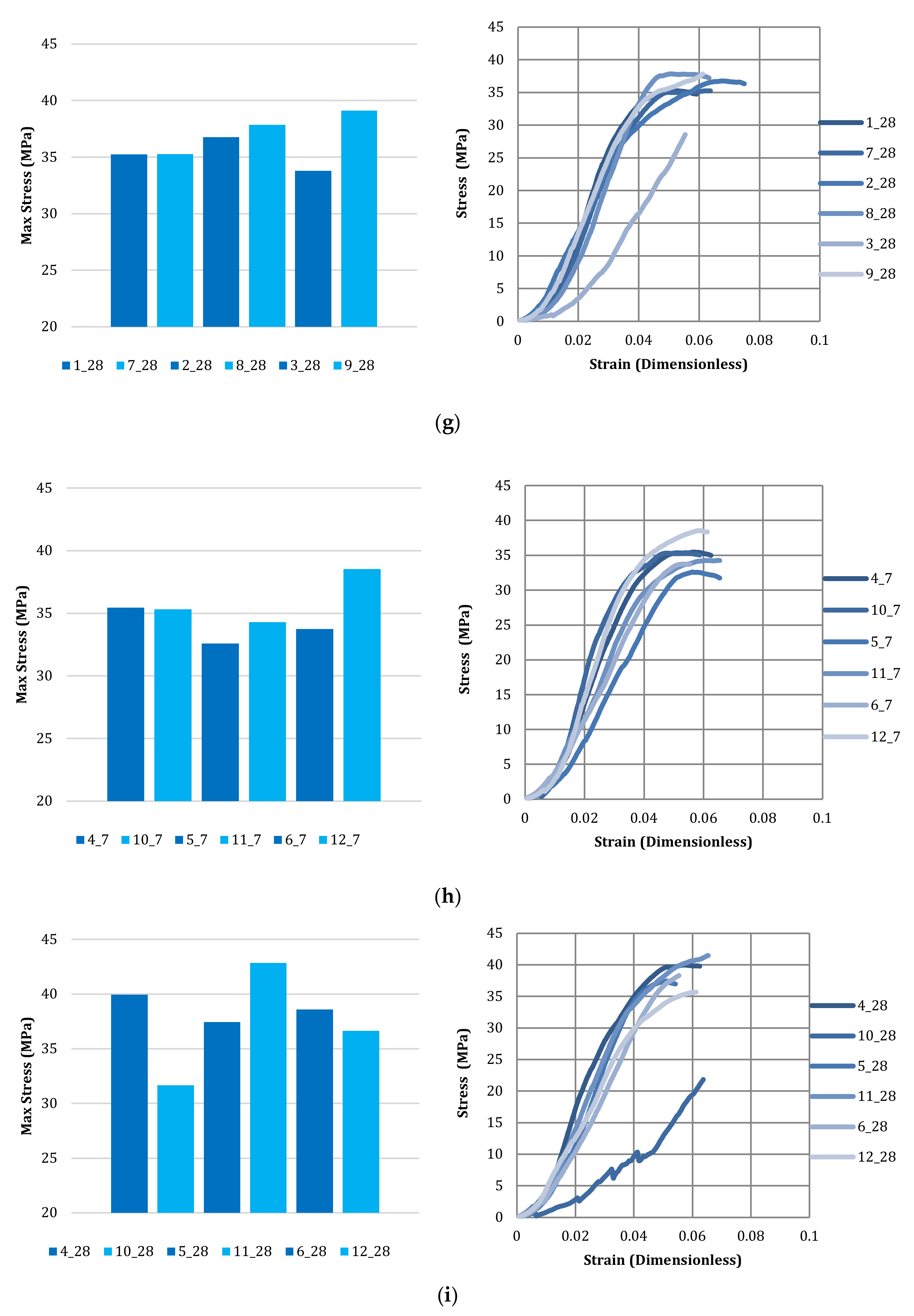
2.5. Compressive Strength Test

The compressive strength of the bricks helps us to understand the extent to which the kimberlite can be valorized as a building material. The concrete brick compressive strength testing was done in accordance with the ASTM C 67 code in an MTS® compression machine (MTS, Eden Prairie, MN, USA), as shown in Figure 4. Two metal plates, the size of the top face of the brick, were used to distribute the stress throughout the brick while under compression. The strain rate was fixed at 5 mm per minute and the load rate of four tonnes per minute. The brick’s surface was smoothened and kept under compression. The test was stopped once the brick cracked or the maximum stress was attained.

3. Results and Discussion

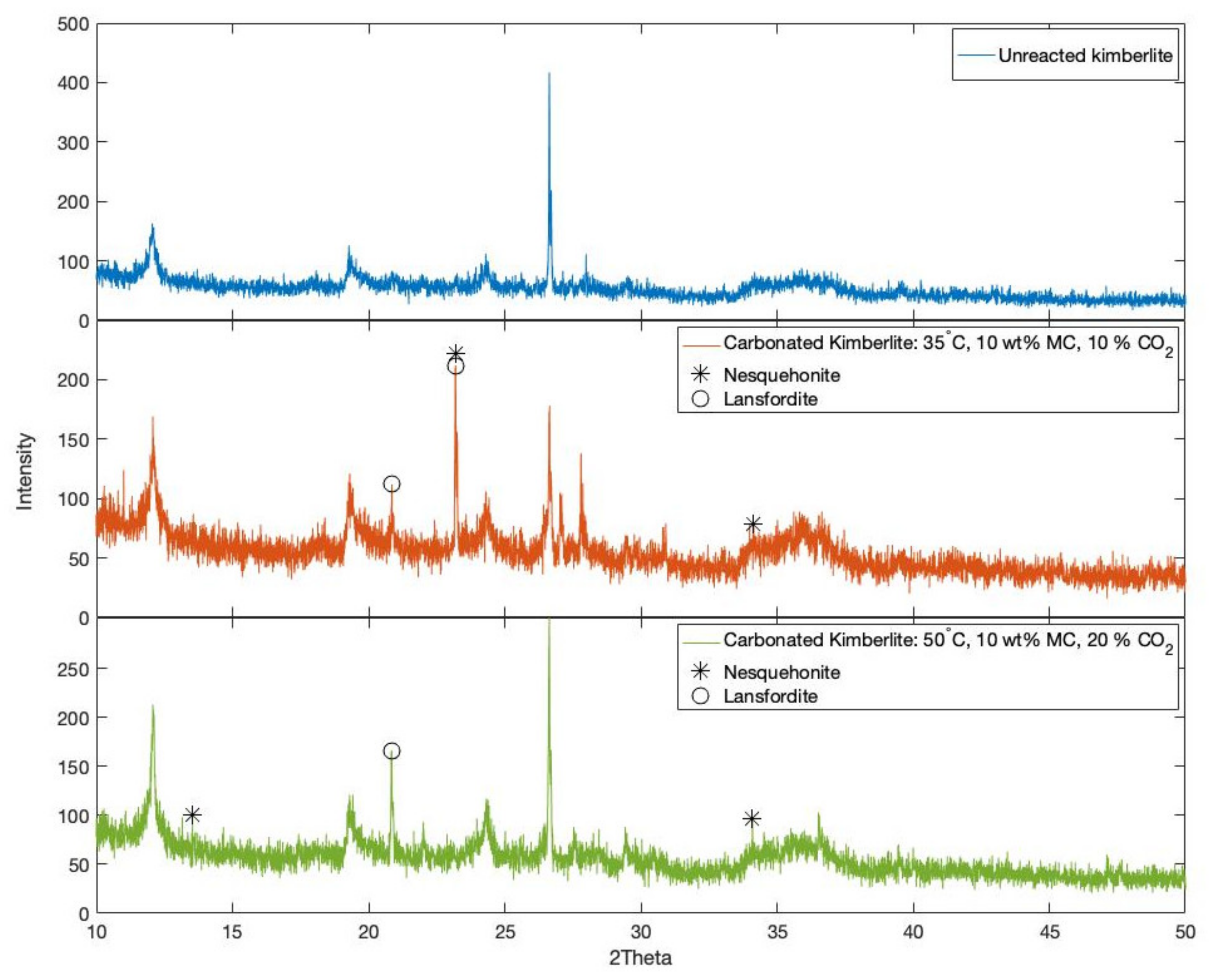
3.1. Kimberlite Carbonation

To determine the properties of CO2 sequestered kimberlite, the furnace test and XRD analysis were conducted. According to the furnace test, the maximum weight loss caused by the release of CO2 was achieved by the kimberlite sample with a moisture content of 20 wt% carbonated at 35 °C and under 20% CO2. This result was expected as high temperature (50 °C) reduces the solubility of CO2 compared to that at the lower temperature (35 °C) [19]. Variation in moisture content of the material did not show an apparent influence on the amount of CO2 sequestered in each sample. In this experiment, moisture contents of 10, 15, and 20 wt% were chosen for assessment because it had been reported that moisture content between 10 and 35 wt% should be maintained to proceed with thin-film carbonation [19]. The distinct effect of varying moisture content was lacking due to manual wetting of the material resulting in heterogeneous moisture content within the same batch of kimberlite. Table 2 provides the weight percentage of CO2 released by each kimberlite sample, which corresponds to the carbonates present after carbonation. It should be noted that these amounts of CO2 present in the samples do not directly reflect the amount of CO2 sequestered through the thin-film carbonation as they include the amount of CO2 that pre-existed prior to carbonation (4.32 wt%), due to the carbonate content of kimberlite (mainly calcite). Thus, the greatest gain in CO2 was approximately 3.7 wt% for the sample carbonated at 35 °C, 20% CO2 concentration, and 20% moisture content.
Figure 5 shows the XRD diffractograms that depict the formation of hydrated magnesium carbonates in the form of nesquehonite (MgCO3·3H2O) and lansfordite (MgCO3·5H2O) in thin-film carbonated kimberlite at 35 and 50 °C. It is predicted that the additional amount of calcium carbonates such as calcite precipitated due to carbonation; however, this additional formation is not detectable by qualitative XRD analysis as calcite already pre-existed in the unreacted kimberlite. Some carbonates that form under mild conditions can also be amorphous, and hence undetectable by XRD while being part of the CO2 released during the furnace test. Formation of nesquehonite and lansfordite was exhibited in most carbonated kimberlite samples, with certain samples containing larger peaks of the former, which is more thermodynamically stable, and certain samples containing larger peaks of the latter, which is less stable thermodynamically. The formation of nesquehonite in samples carbonated at 35 °C and 50 °C is in agreement with results obtained in published studies, which have elucidated that nesquehonite precipitates at temperatures ranging from 25 °C to 55 °C [34,35]. Lansfordite is known to convert to nesquehonite above 10 °C, but has been reported to co-occur with nesquehonite in certain ambient and accelerated carbonation systems [36,37], as it can be kinetically favored as a precursor carbonate phase under mild conditions. On the other hand, hydromagnesite (Mg5(CO3)4(OH)2·4H2O) and magnesite (MgCO3) were not observed as they are known to precipitate at higher temperatures of 60–95 °C and 105 °C, respectively.

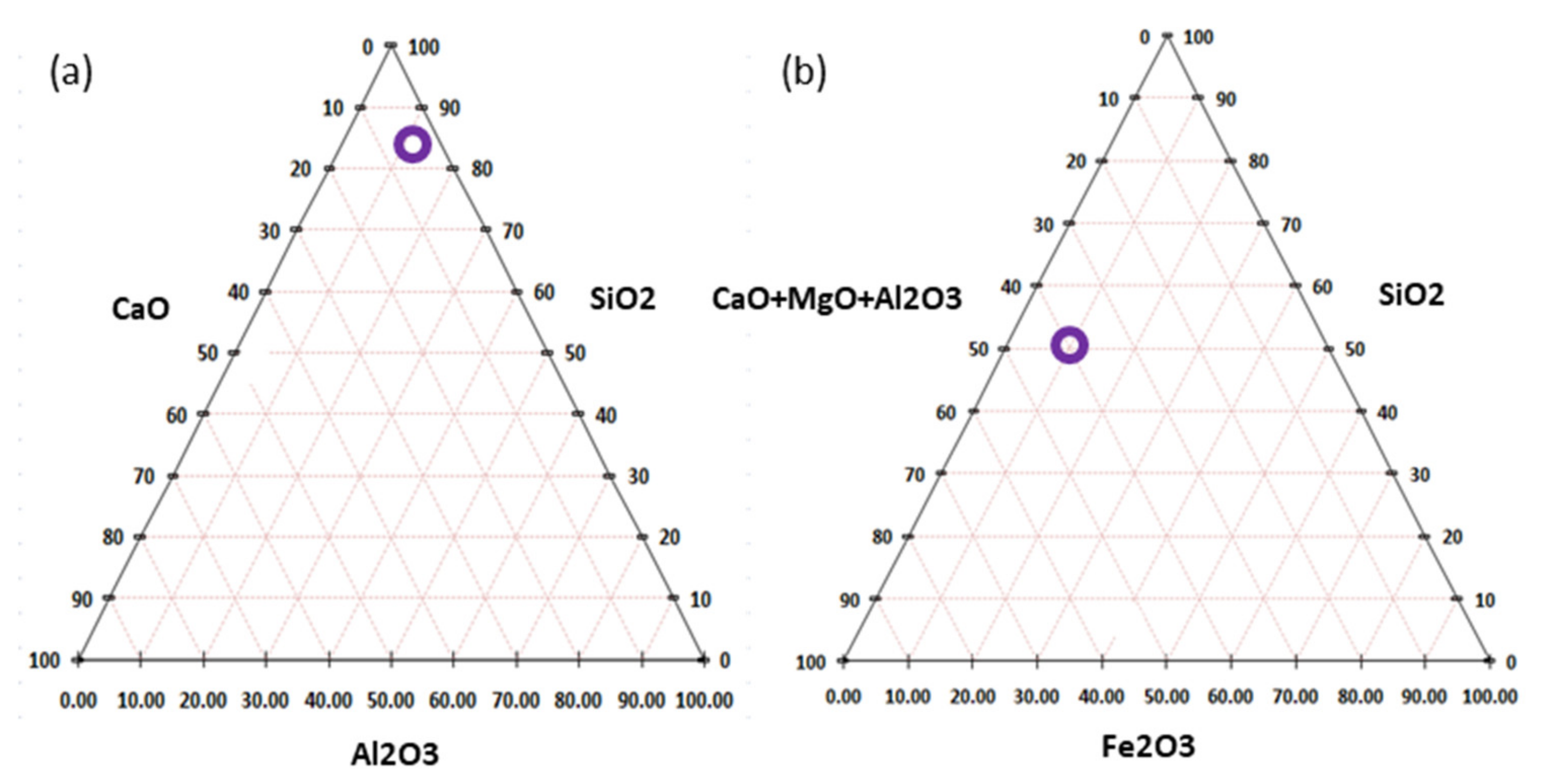
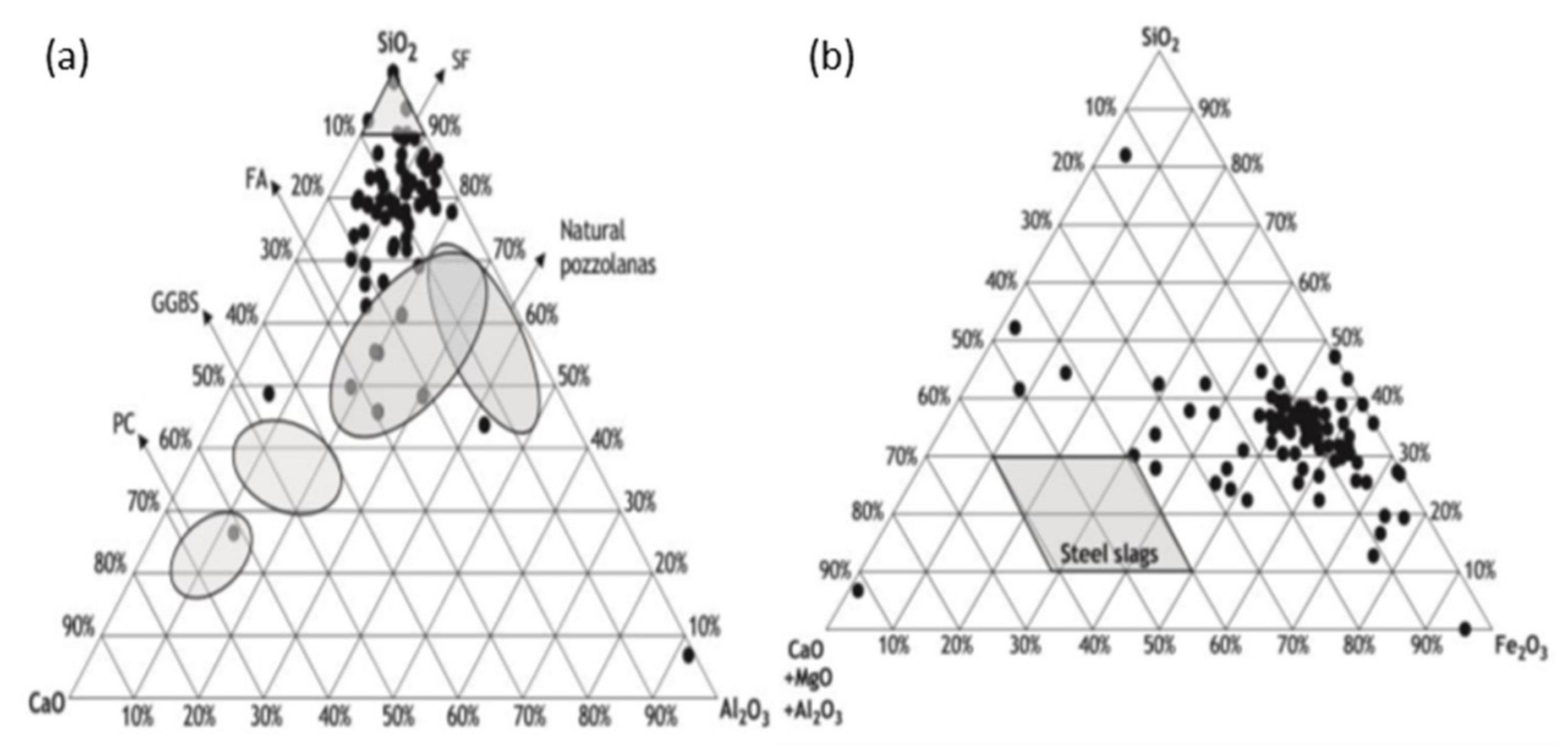
3.2. Binding Properties of Kimberlite

The two ternary diagrams in Figure 6 show the kimberlite’s elemental composition determined by WDXRF according to two different ternary systems. The first system consists of CaO, Al2O3, and SiO2, and the second consists of CaO + MgO + Al2O3, Fe2O3, and SiO2. These systems contain the fundamental compounds that provide the pozzolanic properties of a mineral, and used to compare pozzolanic properties between different materials (as shown in Figure 7). By comparing Figure 6a and Figure 7a, it can be said that kimberlite is comparable to fly ashes and natural pozzolanas (volcanic ash) in terms of its chemical composition. Its texture and fineness are likewise comparable, and this helps in reducing the voids in the brick matrix and thus increases the strength and bulk density of the brick. Comparing Figure 6b and Figure 7b, kimberlite is comparable to low iron content steel and copper slags, which is desirable to avoid rust coloration and minimize specific density of the brick.
Furthermore, according to ASTM C618 [39], the criteria to be satisfied to act as a pozzolanic material is that the total amount of SiO2, Al2O3, and Fe2O3 should be a minimum of 70.0% of the total chemical composition, and loss on ignition should be at most 10.0%. From our results from the WDXRF, the sum of these oxide constituents was 64.59%. Though the sum percentage was less when compared to the criteria, the carbonation of molded bricks in the CO2 incubator for 24 h, prior to demolding, can help in the production of carbonates that contribute to strength development [40].

3.3. Initial Water Absorption of Bricks

The permeability of water through capillary action and the water retention capacity of the bricks highly define its durability. Water absorption can also change the water-to-binder ratio and affect the modulus of elasticity of the brick. The amount of water absorption is also determined by the type of aggregate. Kimberlite is fine in nature when ground, and has a high composition of SiO2, making it a possible alternative for use in concrete as well as an aggregate substitute for sand, which is a finite natural resource and scarce in some regions.
Table 3 presents the calculated initial water absorption of the bricks. The test results showed that a minimum amount of water was absorbed into the pores and cement matrix of the bricks. It proved that there was a low volume of air voids, and thus the bricks were densely packed. The standard specifies that the water absorption for bricks should be less than 7% to have high durability and resistance to freeze and thaw effect. From the Table 3 results, it is clear that the initial water absorption was less than 2%, thus would be expected to be durable and resistant to the heat and thaw effect.

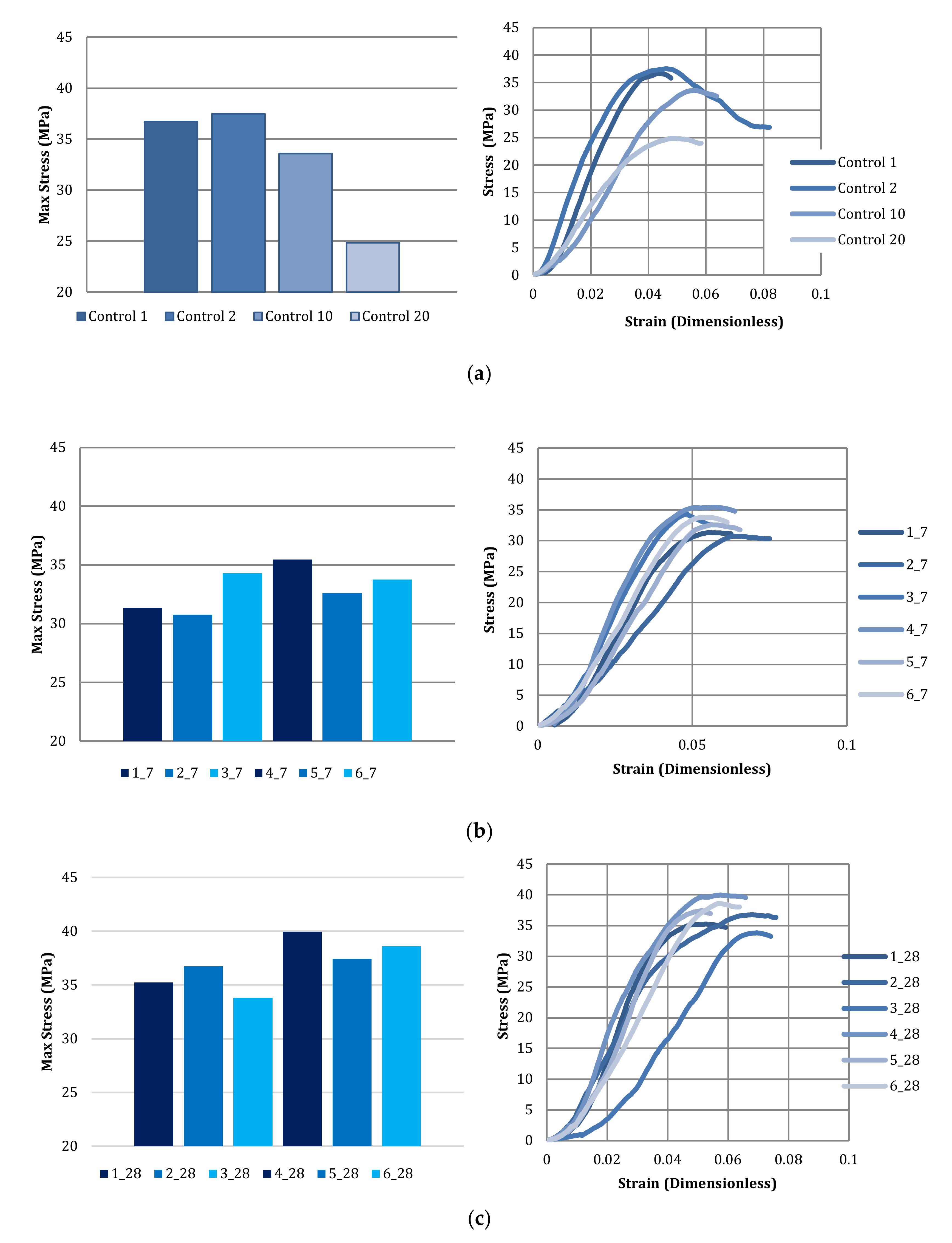
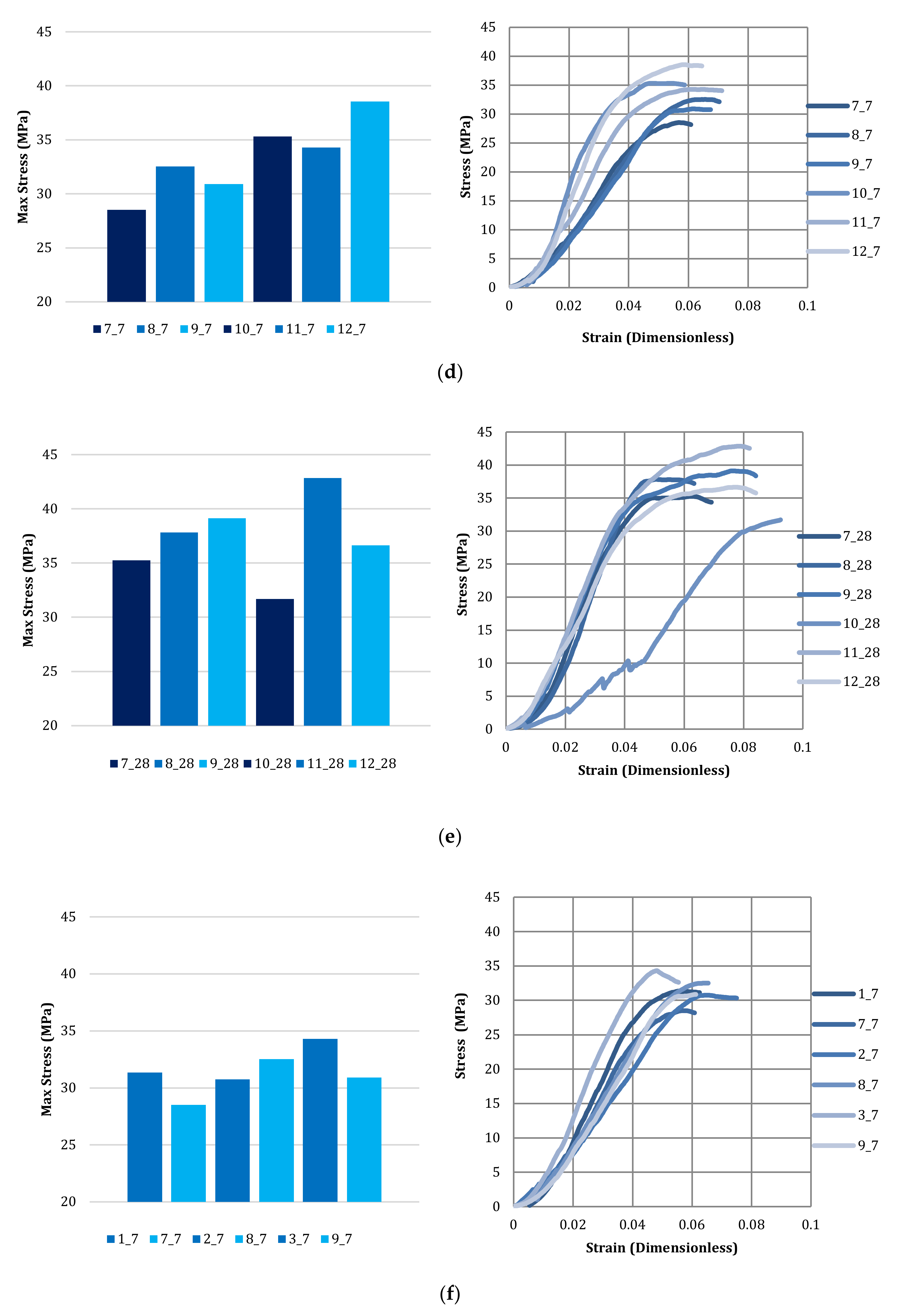
3.4. Compressive Strength of Bricks

According to the ASTM standards, the difference in strength between the 28th and 7th day concrete cement block should be 33.33%. This trend was witnessed throughout the samples, on average, with very few in deviation. Thus, the results plotted in Figure 8 are deemed reliable. For reference, the typical required compressive strength of masonry bricks at 28 days, according to the Canadian Concrete Masonry Producers Association, is between 15 and 40 MPa, mainly depending on the content of cement and the content and type of aggregate content, and aggregate type [41]. Typically, unit compressive strengths at 28 days can range from 15 MPa to 40 MPa. The ASTM specifies a minimum compressive strength from 10.3 to 55.2 MPa for applications ranging from lightest duty (building brick under negligible weathering) to strictest duty (paving brick under severe weathering), respectively [42].
The control graph in Figure 8a shows that the bricks made from 10% replacement (control 10) and 20% replacement (control 20) of cement by unreacted kimberlite had −10% and −30% reduced strength, respectively, when compared to the standard controls. Still, the stress-strain profiles of all controls remained similar, and followed the expected cracking/deforming/failure behavior, making these unreacted kimberlite bricks practically applicable as there will not be sudden failures of the bricks under loading. Still, it is clear that excessive replacement of unreacted kimberlite reduces the applicability of such bricks to a narrower range of service duties.
By comparing the graphs from Figure 8b–i, it can be seen that, in general (with few deviations), the compressive strength of bricks cast with kimberlite carbonated at the highest CO2% (20%) and moisture content (20%) reached higher values. These conditions are those that promote kimberlite thin-film carbonation, as higher CO2% accelerates mineral dissolution and subsequent carbonate precipitation, and higher moisture content maintains the solids adequately wet during thin-film carbonation. Hence, kimberlite that is better carbonated is seen to benefit the compressive strength of bricks that contain it as a partial replacement for cement. Amorphous silica (SiO2) is a by-product of the carbonation of silicates, and this can contribute to strength gain during concrete curing. Additionally, small carbonate crystals can help fill and densify the concrete matrix.
By comparing the graphs from Figure 8f–i, the carbonation temperature effect can be more easily contrasted. The effect of carbonation temperature on compressive strength is not very clear, though there are more bricks prepared with kimberlite carbonated at higher temperature with greater compressive strength than bricks prepared with kimberlite carbonated at lower temperature. However, at lower carbonation moisture content, a higher temperature carbonation resulted, generally, in lower brick strength. This can be explained by the samples drying out more quickly at elevated temperature in thin-film carbonation, thus reducing the carbonation extent and making the mineral paste less evenly carbonated (pastes dry out first near the surface).
It is important to note that optimal thin-film carbonation conditions not only aim to maximize CO2 uptake of the mineral paste on average, but also aim to evenly carbonate the paste (from surface to depth), and the two are not necessarily conducted simultaneously. For example, bricks 3 and 10 had the worst strength performance, reaching the slowest maximum strengths and deforming sooner than the other bricks. Condition 3 used the highest moisture content with lowest CO2% and temperature, which can hinder CO2 transport to the mineral surface as a result of paste pore flooding. Condition 10, conversely, used the highest temperature and CO2% with the lowest moisture content, which can lead to the paste drying out more quickly. In both cases, uneven carbonation may be at fault, since in terms of furnace test results (Table 2), these samples are not too different than the others. It is interesting to note that these two conditions are at opposite ends of the process conditions envelope tested, which means that the other conditions are closer to optimal.
The compressive strength results, together with stress-strain curves, support the idea that alkaline earth metal oxides combine with CO2 to produce hard carbonates. Thus, the increase in strength in concrete prepared with carbonated kimberlite, rather than unreacted kimberlite, is directly related to the production of carbonates in the thin-film carbonated paste mix. These results show kimberlite’s potential as a binder replacement for bricks, and can be expanded to other concrete components for better valorization. More tests should be done with various CO2%, moisture contents and temperatures to optimize the CO2 uptake of the mineral paste and the subsequent strength gain of the concrete.

4. Conclusions

CCU by accelerated CO2 mineralization processes is a promising technology to combat greenhouse gas emissions by substituting traditional products with the long-scale storage of CO2. Though the amount of CO2 sequestered per tonne of carbonated kimberlite, under mild conditions, is comparatively low (up to 3.7 wt% as furnace test results showed), and the process demands energy, continuous research and innovation in the acceleration of mineral carbonation and process intensification can provide the breakthrough that it needs. From the result of compressive strength of the brick, very few samples were unsuitable due to deviated values. This may be due to uneven carbonation of kimberlite replaced in those bricks, but also due to improper compaction, mixing of the particles, surface finish, or orientation of the brick during testing. The optimum concrete mix is defined based on the strength that is demanded by the end user. The characteristic strength of cement bricks is expected to reduce with an increase in the use of kimberlite as a cement replacement beyond the values tested in this study, but carbonation was shown to improve the properties of kimberlite as a cement replacement.
In future research, the amount of Mg- and Ca-carbonates produced by CO2 sequestration in kimberlite through various accelerated and intensified mineral carbonation methods should be tested along with long-term studies to find the durability. Innovation in accelerated carbonation techniques is much needed for these studies. Focus on the physical properties such as kimberlite from various sources should be investigated to certify its binder characteristics by its composition. The mineralogy of the material, leaching properties, physical and mechanical properties like abrasion resistance, shape, specific gravity, bulk density, voids, and particle size distribution is much needed to understand its potential as aggregate and admixture. The effect of substituting kimberlite for cement on greenhouse gas emissions should be analyzed for further insight. Life cycle assessment (LCA) on the valorization process helps us to better understand the process energy demand and determine the feasibility of this process.
This study helps in reusing a material, reduces carbon footprint by storing the CO2 permanently in the material, reduces the usage of other resources, minimizes environmental impact, and valorizes mining waste by-product.

Author Contributions

Conceptualization, R.M.S.; Methodology, C.C. and R.M.S.; Investigation, C.C., S.C., and H.F.; Resources, R.M.S.; Writing—original draft preparation, C.C., S.C., and Y.E.C.; Writing—review and editing, Y.E.C., H.F., and R.M.S.; Supervision, R.M.S.; Project administration, R.M.S.; Funding acquisition, C.C., S.C., and R.M.S. All authors have read and agreed to the published version of the manuscript.

Funding

This research was funded by the Mitacs Globalink program, Barrett Family grant, and the Natural Sciences and Engineering Research Council of Canada (NSERC) Discovery Grant.

Acknowledgments

The authors thank the support of Mitacs for the Globalink research funding provided to C.C. and S.C.; the Natural Sciences and Engineering Research Council of Canada for the Discovery Grant research funding that supports the graduate bursaries of Y.E.C. and H.F.; the Barrett Family for the Barrett Grant research funding provided to support the acquisition of laboratory equipment used in this study; and De Beers Canada Inc. for providing the kimberlite tailings.

Conflicts of Interest

The authors declare no conflicts of interest.

References

  1. Gibbs, M.J.; Soyka, P.; Conneely, D. Good Practice Guidance and Uncertainty Management in National Greenhouse Gas Inventories. 2001. Available online: https://www.ipcc-nggip.iges.or.jp/public/gp/english/ (accessed on 4 June 2020).
  2. Gavali, H.R.; Bras, A.; Faria, P.; Ralegaonkar, R.V. Development of sustainable alkali-activated bricks using industrial wastes. Constr. Build. Mater. 2019, 215, 180–191. [Google Scholar] [CrossRef]
  3. Adiansyah, J.S.; Rosano, M.; Vink, S.; Keir, G. A framework for a sustainable approach to mine tailings management: Disposal strategies. J. Clean. Prod. 2015, 108, 1050–1062. [Google Scholar] [CrossRef] [Green Version]
  4. Edraki, M.; Baumgartl, T.; Manlapig, E.; Bradshaw, D.; Franks, D.M.; Moran, C.J. Designing mine tailings for better environmental, social and economic outcomes: A review of alternative approaches. J. Clean. Prod. 2014, 84, 411–420. [Google Scholar] [CrossRef]
  5. Poinot, T.; Laracy, M.E.; Aponte, C.; Jennings, H.M.; Ochsendorf, J.A.; Olivetti, E.A. Beneficial use of boiler ash in alkali-activated bricks. Resour. Conserv. Recycl. 2018, 128, 1–10. [Google Scholar] [CrossRef]
  6. Zhang, L. Production of bricks from waste materials—A review. Constr. Build. Mater. 2013, 47, 643–655. [Google Scholar] [CrossRef]
  7. WBCSD. Cement Technology Roadmap 2009—Carbon Emissions Reductions up to 2050. 2009. Available online: http://www.cbcsd.org.cn/sjk/nengyuan/roadmap/20130516/download/Cement_Roadmap.pdf (accessed on 4 June 2020).
  8. Balasubramanian, J.; Sabumon, P.C.; Lazar, J.U.; Ilangovan, R. Reuse of textile effluent treatment plant sludge in building materials. Waste Manag. 2006, 26, 22–28. [Google Scholar] [CrossRef] [PubMed]
  9. Wolff, E.; Schwabe, W.K.; Conceição, S.V. Utilization of water treatment plant sludge in structural ceramics. J. Clean. Prod. 2015, 96, 282–289. [Google Scholar] [CrossRef]
  10. Ukwatta, A.; Mohajerani, A. Characterisation of fired-clay bricks incorporating biosolids and the effect of heating rate on properties of bricks. Constr. Build. Mater. 2017, 142, 11–22. [Google Scholar] [CrossRef]
  11. Rani, M.Y.; Bhagawan, D.; Himabindu, V.; Reddy, V.V.; Saritha, P. Preparation and characterization of green bricks using pharmaceutical industrial wastes. Environ. Sci. Pollut. Res. 2016, 23, 9323–9333. [Google Scholar] [CrossRef]
  12. Goel, G.; Kalamdhad, A.S. An investigation on use of paper mill sludge in brick manufacturing. Constr. Build. Mater. 2017, 148, 334–343. [Google Scholar] [CrossRef]
  13. Goel, G.; Kalamdhad, A.S. Degraded municipal solid waste as partial substitute for manufacturing fired bricks. Constr. Build. Mater. 2017, 155, 259–266. [Google Scholar] [CrossRef]
  14. Demir, I. An investigation on the production of construction brick with processed waste tea. Build. Environ. 2006, 41, 1274–1278. [Google Scholar] [CrossRef]
  15. Mekki, H.; Ammar, E.; Anderson, M.; Zina, M.B. The recycling of olive oil mill by-products in bricks. Ann. Chimie Sci. Materiaux 2003, 28, 109–127. [Google Scholar] [CrossRef]
  16. Mekki, H.; Anderson, M.; Amar, E.; Skerratt, G.R.; Zina, M.B. Olive oil mill waste water as a replacement for fresh water in the manufacture of fired clay bricks. J. Chem. Technol. Biotechnol. 2006, 81, 1419–1425. [Google Scholar] [CrossRef]
  17. Cotes Palomino, M.T.; Martínez García, C.; Iglesias Godino, F.J.; Eliche Quesada, D.; Corpas Iglesias, F.A. Study of the wet pomace as an additive in ceramic material. Desalin. Water Treat. 2016, 57, 2712–2718. [Google Scholar] [CrossRef]
  18. José, A.; Lorite, M.; Jiménez, J.; Castro, E. Valorisation of wastewater from two-phase olive oil extraction in fired clay brick production. J. Hazard. Mater. 2009, 169, 271–278. [Google Scholar]
  19. Santos, R.M.; Van Bouwel, J.; Vandevelde, E.; Mertens, G.; Elsen, J.; Van Gerven, T. Accelerated mineral carbonation of stainless steel slags for CO2 storage and waste valorization: Effect of process parameters on geochemical properties. Int. J. Greenh. Gas Control. 2013, 17, 32–45. [Google Scholar] [CrossRef] [Green Version]
  20. Baciocchi, R.; Costa, G.; Polettini, A.; Pomi, R. Influence of particle size on the carbonation of stainless steel slag for CO2 storage. Energy Procedia 2009, 1, 4859–4866. [Google Scholar] [CrossRef] [Green Version]
  21. Bodénan, F.; Bourgeois, F.; Petiot, C.; Augé, T.; Bonfils, B.; Julcour-Lebigue, C.; Guyot, F.; Boukary, A.; Tremosa, J.; Lassin, A.; et al. Ex situ mineral carbonation for CO2 mitigation: Evaluation of mining waste resources, aqueous carbonation processability and life cycle assessment (Carmex project). Miner. Eng. 2014, 59, 52–63. [Google Scholar] [CrossRef] [Green Version]
  22. Romanov, V.; Soong, Y.; Carney, C.; Rush, G.E.; Nielsen, B.; O’Connor, W. Mineralization of carbon dioxide: A literature review. ChemBioEng Rev. 2015, 2, 231–256. [Google Scholar] [CrossRef]
  23. Ostovari, H.; Sternberg, A.; Bardow, A. Rock ‘n’ use of CO2: Carbon footprint of carbon capture and utilization by mineralization. Sustain. Energy Fuels 2020. [Google Scholar] [CrossRef]
  24. O’Connor, W.K.; Dahlin, D.C.; Rush, G.E.; Gerdemann, S.J.; Penner, L.R.; Nilsen, D.N. Aqueous Mineral Carbonation; Final Report DOE/ARC-TR-04-002; US Department of Energy: Albany, OR, USA, 2005.
  25. Wang, X.; Maroto-Valer, M.M. Integration of CO2 capture and mineral carbonation by using recyclable ammonium salts. ChemSusChem 2011, 4, 1291–1300. [Google Scholar] [CrossRef] [Green Version]
  26. Li, J.; Hitch, M. Mechanical activation of magnesium silicates for mineral carbonation, a review. Miner. Eng. 2018, 128, 69–83. [Google Scholar]
  27. Ghoorah, M.; Dlugogorski, B.Z.; Balucan, R.D.; Kennedy, E.M. Selection of acid for weak acid processing of wollastonite for mineralisation of CO2. Fuel 2014, 122, 277–286. [Google Scholar] [CrossRef]
  28. Mervine, E.M.; Wilson, S.A.; Power, I.M.; Dipple, G.M.; Turvey, C.C.; Hamilton, J.L.; Vanderzee, S.; Raudsepp, M.; Southam, C.; Matter, J.M.; et al. Potential for offsetting diamond mine carbon emissions through mineral carbonation of processed kimberlite: An assessment of De Beers mine sites in South Africa and Canada. Mineral. Petrol. 2018, 112, S755–S765. [Google Scholar] [CrossRef]
  29. Bodor, M.; Santos, R.M.; Kriskova, L.; Elsen, J.; Vlad, M.; Van Gerven, T. Susceptibility of mineral phases of steel slags towards carbonation: Mineralogical, morphological and chemical assessment. Eur. J. Mineral. 2013, 25, 533–549. [Google Scholar] [CrossRef]
  30. Bukowski, J.M.; Berger, R.L. Reactivity and strength development of CO2 activated non-hydraulic calcium silicates. Cem. Concr. Res. 1979, 9, 57–68. [Google Scholar] [CrossRef]
  31. Van der Plas, G.; Limaye, P.; Loi, I.; Mercha, A.; Oprins, H.; Torregiani, C.; Thijs, S.; Linten, D.; Stucchi, M.; Katti, G.; et al. Design issues and considerations for low-cost 3-D TSV IC technology. IEEE J. Solid-State Circuits 2010, 46, 293–307. [Google Scholar] [CrossRef] [Green Version]
  32. Santos, R.M.; Van Gerven, T. Process intensification routes for mineral carbonation. Greenh. Gases Sci. Technol. 2010, 1, 287–293. [Google Scholar] [CrossRef] [Green Version]
  33. ASTM International. ASTM: C67-14, Standard Test Methods for Sampling and Testing Brick and Structural Clay Tile; ASTM: West Conshohocken, PA, USA, 2014. [Google Scholar]
  34. Morgan, B.; Wilson, S.A.; Madsen, I.C.; Gozukara, Y.M.; Habsuda, J. Increased thermal stability of nesquehonite (MgCO3·3H2O) in the presence of humidity and CO2: Implications for low-temperature CO2 storage. Int. J. Greenh. Gas Control. 2015, 39, 366–376. [Google Scholar] [CrossRef]
  35. Zhang, Z.; Zheng, Y.; Ni, Y.; Liu, Z.; Chen, J.; Liang, X. Temperature-and pH-dependent morphology and FT-IR analysis of magnesium carbonate hydrates. J. Phys. Chem. B 2006, 110, 12969–12973. [Google Scholar] [CrossRef]
  36. Power, I.M.; Wilson, S.A.; Harrison, A.L.; Dipple, G.M.; Mccutcheon, J.; Southam, G.; Kenward, P.A. A depositional model for hydromagnesite–magnesite playas near Atlin, British Columbia, Canada. Sedimentology 2014, 61, 1701–1733. [Google Scholar] [CrossRef]
  37. Hwang, K.-Y.; Kim, J.Y.; Phan, H.Q.H.; Ahn, J.-Y.; Kim, T.Y.; Hwang, I. Effect of CO2 concentration on strength development and carbonation of a MgO-based binder for treating fine sediment. Environ. Sci. Pollut. Res. 2018, 25, 22552–22560. [Google Scholar] [CrossRef] [PubMed]
  38. Obe, R.K.D.; De Brito, J.; Mangabhai, R.; Lye, C.Q. Sustainable Construction Materials: Copper Slag; Woodhead Publishing: Cambridge, UK, 2016. [Google Scholar] [CrossRef]
  39. ASTM International. ASTM: C618-19, Standard Specification for Coal Fly Ash and Raw or Calcined Natural Pozzolan for Use in Concrete; ASTM: West Conshohocken, PA, USA, 2012. [Google Scholar]
  40. Salman, M.; Cizer, Ö.; Pontikes, Y.; Santos, R.M.; Snellings, R.; Vandewalle, L.; Blanpain, B. Van Balen, K. Effect of accelerated carbonation on AOD stainless steel slag for its valorisation as a CO2-sequestering construction material. Chem. Eng. J. 2014, 246, 39–52. [Google Scholar] [CrossRef] [Green Version]
  41. Canadian Concrete Mansory Producers Association. Physical Properties, Metric Technical Manual. 2020. Available online: https://ccmpa.ca/wp-content/uploads/2012/02/Final2013Sec4.pdf (accessed on 23 June 2013).
  42. Kuranchie, F.A.; Shukla, S.K.; Habibi, D. Utilisation of iron ore mine tailings for the production of geopolymer bricks. Int. J. Min. Reclam. Environ. 2016, 30, 92–114. [Google Scholar] [CrossRef]
Figure 1. X-ray diffraction (XRD) diffractogram of fine processed kimberlite (FPK), sourced from the Gahcho Kué Diamond Mine, Northwest Territories, Canada.
Minerals 10 00611 g001
Figure 2. Compacted mix in the brick molds.
Minerals 10 00611 g002
Figure 3. Immersed bricks for the water absorption test.
Minerals 10 00611 g003
Figure 4. Compression test in the MTS® compression machine.
Minerals 10 00611 g004
Figure 5. Comparison between the XRD diffractograms of unreacted kimberlite and thin-film carbonated kimberlite at 35 °C, 10 wt% moisture content, and 10% CO2 concentration and at 50 °C, 10 wt% moisture content, and 20% CO2 concentration.
Minerals 10 00611 g005
Figure 6. Ternary diagrams of kimberlite’s elemental composition (circles). (a) SiO2, CaO, and Al2O3 system; (b) Fe2O3, CaO + MgO + Al2O3, and SiO2 system.
Minerals 10 00611 g006
Figure 7. Ternary diagrams for other existing binder materials (a) and steel slag (b), where dots represent copper slag compositions [38]. Reused with permission from Elsevier (License Number 4842140657812).
Minerals 10 00611 g007
Figure 8. (a) Comparing the compressive strength and stress strain curves of the standard (controls 1 and 2) and unreacted kimberlite (controls 10 and 20) control bricks. (b) Comparing the compressive strength and stress-strain curves of bricks with the replacement of kimberlite carbonated at constant temperature (35 °C), grouped by increasing moisture content (1 and 4 = 10%; 2 and 5 = 15%; 3 and 6 = 20%) then by increasing CO2% (1, 2, and 3 = 10%, 4, 5, and 6 = 20%) on the seventh day of curing. (c) Comparing the compressive strength and stress-strain curves of bricks with replacement kimberlite carbonated at constant temperature (35 °C), grouped by increasing moisture content (1 and 4 = 10%; 2 and 5 = 15%; 3 and 6 = 20%) then by increasing CO2% (1, 2, and3 = 10%, 4, 5, and 6 = 20%) on the 28th day. (d) Comparing the compressive strength and stress-strain curves of bricks with replacement kimberlite carbonated at constant temperature (50 °C), grouped by increasing moisture content (7 and 10 = 10%; 8 and 11 = 15%; 9 and 12 = 20%) then by increasing CO2% (7, 8, and 9 = 10%, 10, 11, and 12 = 20%) on the seventh day. (e) Comparing the compressive strength and stress-strain curves of bricks with replacement kimberlite carbonated at constant temperature (50 °C), grouped by increasing moisture content (7 and 10 = 10%; 8 and 11 = 15%; 9 and 12 = 20%) then by increasing CO2% (7, 8, and 9 = 10%, 10, 11, and 12 = 20%) on the 28th day. (f) Comparing the compressive strength and stress-strain curves of bricks with replacement kimberlite carbonated at constant CO2% (10%), grouped by increasing moisture content (1 and 7 = 10%; 2 and 8 = 15%; 3 and 9 = 20%) and then by temperature (1, 2, and 3 = 35 °C; 7, 8, and 9 = 50 °C) on the seventh day. (g) Comparing the compressive strength and stress-strain curves of bricks with replacement kimberlite carbonated at constant CO2% (10%), grouped by increasing moisture content (1 and 7 = 10%; 2 and 8 = 15%; 3 and 9 = 20%) and then by temperature (1, 2, and 3 = 35 °C; 7, 8, and 9 = 50 °C) on the 28th day. (h) Comparing the compressive strength and stress-strain curves of bricks with replacement kimberlite carbonated at constant CO2% (20%), grouped by increasing moisture content (4 and 10 = 10%; 5 and 11 = 15%; 6 and 12 = 20%) and then by temperature (4, 5, and 6 = 35 °C; 10, 11, and 12 = 50 °C) on the seventh day. (i) Comparing the compressive strength and stress-strain curves of bricks with replacement kimberlite carbonated at constant CO2% (20%), grouped by increasing moisture content (4 and 10 = 10%; 5 and 11 = 15%; 6 and 12 = 20%) and then by temperature (4, 5, and 6 = 35 °C; 10, 11, and 12 = 50 °C) on the 28th day. Bar graphs comparing the maximum compressive strength, and graphs comparing the stress-strain curves of bricks prepared without (a) and with (bi) carbonated kimberlite replacement as a function of various carbonation parameters: temperature, moisture content, and CO2%.
Minerals 10 00611 g008aMinerals 10 00611 g008bMinerals 10 00611 g008c
Table 1. The brick numbers that specify its curing duration and the carbonated kimberlite sample used.
Brick NumberCarbonated Kimberlite Material—10% Replacement
1 (7 days)10% Moisture Content, 10% CO2, 35 °C
1 (28 days)
2 (7 days)15% Moisture Content, 10% CO2, 35 °C
2 (28 days)
3 (7 days)20% Moisture Content, 10% CO2, 35 °C
3 (28 days)
4 (7 days)10% Moisture Content, 20% CO2, 35 °C
4 (28 days)
5 (7 days)15% Moisture Content, 20% CO2, 35 °C
5 (28 days)
6 (7 days)20% Moisture Content, 20% CO2, 35 °C
6 (28 days)
7 (7 days)10% Moisture Content, 10% CO2, 50 °C
7 (28 days)
8 (7 days)15% Moisture Content, 10% CO2, 50 °C
8 (28 days)
9 (7 days)20% Moisture Content, 10% CO2, 50 °C
9 (28 days)
10 (7 days)10% Moisture Content, 20% CO2, 50 °C
10 (28 days)
11 (7 days)15% Moisture Content, 20% CO2, 50 °C
11 (28 days)
12 (7 days)20% Moisture Content, 20% CO2, 50 °C
12 (28 days)
Table 2. The amount of CO2 released during furnace test from the unreacted and thin-film carbonated kimberlite.
Carbonation ConditionsCarbonated Kimberlite
Temperature (°C)CO2 Concentration (vol%)Moisture Content (wt% w.b.)CO2 Content (wt% d.b.)
Unreacted--4.32
3510107.67
157.92
207.76
3520107.94
157.96
208.04
5010107.52
157.53
207.35
5020107.75
157.62
207.47
d.b.: dry basis; w.b.: wet basis.
Table 3. Initial water absorption of the kimberlite bricks.
Brick NumberInitial Weight (g)Weight after 24 h (g)Initial Water Absorption (%)
1 (7 days)2445.152471.951.096
1 (28 days)2464.872494.951.220
2 (7 days)2490.212523.641.342
2 (28 days)2512.212544.841.299
3 (7 days)2463.272497.161.376
3 (28 days)2479.842514.871.413
4 (7 days)2558.102597.151.526
4 (28 days)2587.642623.461.384
5 (7 days)2561.482590.661.139
5 (28 days)2489.002518.871.200
6 (7 days)2503.732539.111.413
6 (28 days)2551.332581.851.196
7 (7 days)2581.852605.440.914
7 (28 days)2581.572606.610.970
8 (7 days)2566.822591.550.963
8 (28 days)2553.442578.070.965
9 (7 days)2471.972500.821.167
9 (28 days)2541.442570.811.156
10 (7 days)2679.802718.451.442
10 (28 days)2515.912549.811.347
11 (7 days)2536.432568.781.275
11 (28 days)2580.042611.121.205
12 (7 days)2554.702584.451.164
12 (28 days)2563.732597.851.331

