1. Introduction
The extreme intensity of X-rays that can be packed into a tiny beam is just the thing for high-pressure, high-temperature research using the diamond anvil cell (DAC). The appeal of the DAC had always been that so much could be learned, as long as analytical techniques exist that can be used for microscopic samples. I took a position in the Geology Department at Cornell University in 1978. It had been 17 years since my post-doc appointment at Brookhaven National Laboratory on Long Island. When I was there, I had watched the construction of the Alternating Gradient Synchrotron being built for electron-positron collision experiments. When the workmen had left for the day, I explored the partially constructed new facility. I was especially taken by the massive shielding made of salvaged old naval ship decking. When I inquired about its need, I was told it was to shield against synchrotron radiation, something that seemed to be simply a nuisance. I had never paid any more attention to that kind of radiation until the day I arrived at Cornell University for an interview and a tour of campus with Geology’s chairman, Jack Oliver, and was shown the Cornell High Energy Synchrotron Source (CHESS) just being built on the campus.
Figure 1 gives a simplified layout and outlines the basic principles involved in generating X-ray beams that can be used for research. When its capabilities were explained to me, and I learned that synchrotron radiation had acquired its new reputation, I realized that its intense, small X-ray beams and fast X-ray detectors might be the next ideal step for research with the DAC. Fortunately, I was offered the position and immediately started designing the equipment that would be needed to take advantage of its properties. Perhaps diffraction patterns could be made in less time than one week, as was needed on a conventional X-ray source, such as one that I had used earlier at the University of Rochester. Maybe data on the effects of high pressures and temperatures could be collected much more rapidly. The director of CHESS, Bob Batterman, and the beamline scientists were very generous and allowed some of us to make preliminary runs on CHESS before it was officially opened for users. The beamline scientists were extremely helpful and had my students and me up and running smoothly in a few days. These runs were so successful that I knew merging the DAC with synchrotron radiation would be a fascinating line of research for a long time to come. I learned many years later from Bob Batterman at his retirement that I was, in fact, the first person to formally apply for beamtime at CHESS when it was opened up to general users. The prospect of being able to collect a diffraction pattern at high pressures and temperatures in a few seconds rather than a week was irresistible. Later, when a visual camera with a strong lens system was added, visual changes could be correlated with the X-ray observations, and the X-ray beam could be seen for aiming when fluorescent diamond anvils were used. It was possible to watch phase transitions and reactions proceed in real time under either hydrostatic or deviatoric stress.
In addition to X-ray diffraction spectroscopic techniques, such as emission spectroscopy, not only made it possible to determine the compositions of individual phases, but also made it possible to determine the valence states and structures of complex ions in aqueous solution. As beamlines were equipped with specialized instrumentation, researchers happily paid for travel to the nearest synchrotron source or the place equipped with the best instrumentation for their research. Even if numerous trips to a synchrotron source were needed for one research project, it always seemed like a desirable choice. Being on the same campus with CHESS, however, meant that my students and I had no need to travel, and would sometimes be given beamtime when other groups had to cancel. Although CHESS was not the first synchrotron source, it was early enough so that a number of specialized beamlines were developed there. A number of good sites can be found by digital searching for “synchrotron radiation sources world wide”.
2. The Amazing Phenomenon of Synchrotron Radiation
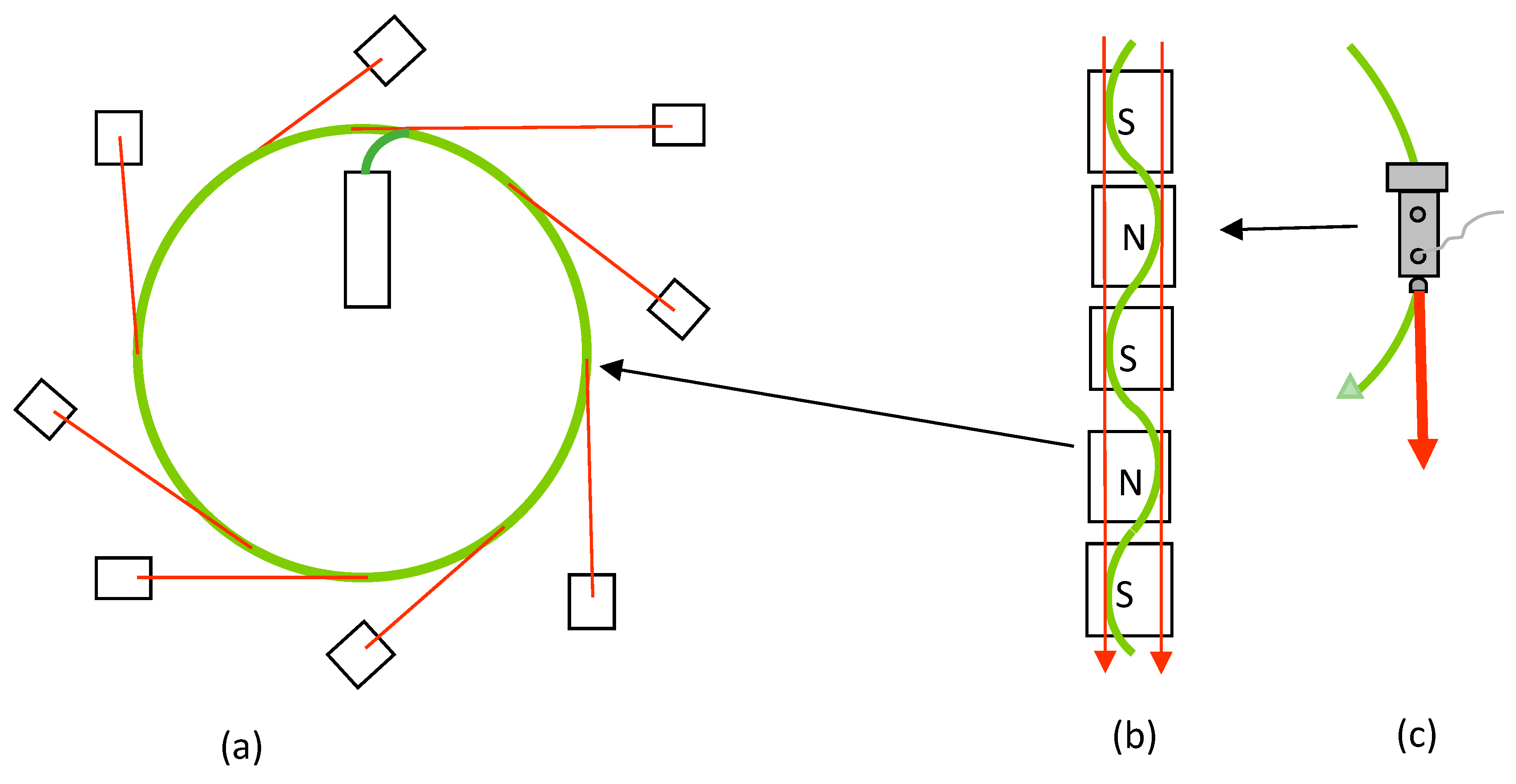
Figure 1 is a simplified layout for a synchrotron storage ring for producing X-ray beams for research experiments.
If the electron-beam energy is high, the frequency of the light is high, e.g., X-rays. Although synchrotron sources can and do produce lower-energy radiation, such as visible light and infrared, these high-energy X-ray beams have been the most valuable for mineral physics. It was found that much more intense beams could be produced if the electron beam passed through a wiggler or undulator so that a series of X-ray beams produced at each bend in the electron beam could be added together. CHESS was instrumental in perfecting them, and today they are the preferred sources for much of synchrotron research. The crest and trough of each wiggle produces an electromagnetic beam; the series of crests and troughs combine to produce a much greater intensity shown by the red arrows. (c) Shows the comparison between the synchrotron phenomenon and a locomotive’s headlight. The electric vector of the generated X-rays is highly oriented by the magnetic fields, so that the polarization is horizontal, a property especially valuable for our research using X-ray spectroscopy.
3. Results of Mineral Physics Research Using Synchrotron Radiation
One of the most interesting and valuable uses of synchrotron radiation for mineral physics was the ability to observe crystal structure change in real time. One of our most successful uses of this capability was the olivine-spinel phase transition which could have important implications for deep focus earthquakes. It had been pointed out by Green, et al. [
1] and Burnley, et al. [
2], that rocks are expected to be so ductile at the depths where deep-focus quakes originate, that a mechanism other than brittle failure must cause them. They suggest that, rather than brittle failure, the olivine-spinel phase transition made the most sense, and that shear stress might be an important mechanism. It occurred to me that we might be able to study the relationship between shear stress and the phase transition, if we were to watch the olivine-spinel transition by X-ray diffraction as the transition was taking place—something that synchrotron radiation would make possible. It might show that shear strain caused by shear stress is an even more intimate part of the transition by promoting the transition that, in turn, increasing the shear stress elsewhere on a fault plane driving additional transition and, in turn, additional phase transition. Perhaps shear strain rather than brittle failure could be shown to trigger failure by a shear mechanism at other points in a fault plane.
My student, Mike Furnish, and I [
3] thought that if we could very slowly increase pressure at a temperature expected at the depth of deep-focus earthquakes, we might learn more about the olivine-spinel phase transition and what triggers it. We designed a gear system that could very slowly increase the pressure as we turned the hand crank on a remote selsyn driver that turned the selsyn motor in the experimental hutch that increased the pressure as the crank was turned. That ability to increase the pressure or halt for an interesting observation in the diffraction pattern was exactly what we needed. We chose fayalite as our sample, mounted it without a gasket and made a series of diffraction patterns over quite a long time, as we slowly increased stress in the form of both isotropic stress (pressure) and shear stress, as a result of the extrusion of sample from between the anvil faces. Finally, we saw a subtle change and slowed progress even further and ultimately halted progress. What we observed amazed us; it was completely unexpected, too good to be true. The transition proceeded by two steps. There were several intermediate diffraction patterns and so we were certain it was real. First, we could clearly see that the oxygen atoms were moving by displacement from their positions in the olivine structure to their positions in the spinel structure while the cations remained in their olivine positions until given more time or more pressure. Then, they slowly migrated by diffusion to the spinel structure positions.
We made a model of the olivine structure out of plastic balls that would let us slide the layers of oxygen atoms over each other. We already suspected that shear stress played a role because of the displacive nature of hexagonal close-packed structure to cubic close-packed structure; we just never expected it to be so visible in our data.
4. A Different Experiment with the Same Conclusions
Pam Burnley joined us as a post-doc. We turned once more to the olivine-spinel transition, as she already had familiarity with it, and found yet another way of showing the connection between shear stress and the olivine-spinel transition. We ran several different olivine compositions in a diamond anvil cell with no gasket, so they would be subjected to radial shear stress as they extruded [
4,
5]. Observations of the extruding sample gave a clear picture of the amount of shear strain as pressure and/or temperature increased. The central pressure was well above the transition pressure for each of the samples. This time we used only a microscope and heated gradually, until color change indicated the high-pressure phase. The high-pressure phase appeared as a ring in every run for every sample. We concluded that this was another sure indication that shear triggered the high-pressure phase. The outer portion of the sample was at too low a pressure and while the center was well above the transition pressure it experienced less shear (
Figure 2).
5. Advanced Photon Source (APS) and Fluid Studies at High Pressures and Temperatures (1995)
As synchrotron sources gained in popularity, the new ones took advantage of technology developed at the earlier ones, so they could add many new analytical techniques with new specialized instrumentation. And so it was with CHESS and the Advanced Photon Source (APS) planned for the Argonne National Laboratory in Illinois. A number of us from Cornell were glad to attend planning sessions and contribute to the design of experimental hutches at APS with an even greater variety of new instrumentation. My colleagues and I made a number of preliminary experimental runs at CHESS to develop methods for studying fluid aqueous solutions, but then realized that what we wanted to do could be done even more easily with the newly developed X-ray spectrometric instruments at APS. For our research on fluid samples at high pressures and temperatures we traveled to Argonne to use the facilities at APS.
Figure 3 shows a diamond anvil cell designed specifically for passing an X-ray beam “between” the upper and lower diamond anvils perpendicular to the load axis of the cell [
6].
Figure 4 is an image of the setup for seeing the X-ray beam so we can aim it through our fluid or mixed-phase samples. Sometimes we use a metal gasket in addition to the recess for the sample; other times we just pressed the two anvil faces together so tightly that the sample cannot leak at the high sample pressures produced by heating (
Figure 4). The choice depended on whether we needed to increase the pressure by squeezing the gasket to reduce sample volume, or whether the pressures resulting from heating were sufficient. We would usually avoid using a gasket when possible so that we could minimize contamination of the sample. The X-ray beam enters “between” the gasket and anvil face or “between” the two anvil faces when no gasket is used. The notches are there to minimize attenuation by diamond. Emitted X-rays from the sample pass out through the notch on the left, where they can be spectrometrically analyzed. The left notch, because it is at a 90° angle to the incident beam, yields the clearest signal for determining absorption, because emission is a direct function of the absorption, while Rayleigh and other forms of scattering not indicative of absorption are minimized, due to the highly polarized nature of the impinging X-ray beam, as described in
Figure 2. We used this method to collect spectra that can be used to produce diagrams of complex ions, like the examples shown in
Figure 5 [
7]. This is valuable information for determining the mobility and reactivity of elements in solution as a function of concentration, pressure and temperature.
As interests in applications of synchrotron radiation to mineral physics research increased, it became clear that the understanding of many samples involves the compositions and properties of fluids and the structures of the ions in them. Virtually all high-pressure-high-temperature natural fluids and supercritical dense vapors are solutions in which minerals are carried, and are therefore very important to understanding hydrothermal, magmatic and nearly all metamorphic processes. Compositions of solutions at high pressure and temperature can be determined by emission spectra. However, it seems odd to speak of the structures of ions in solution, a job that diffraction cannot do, and yet we find that the structures of ions that are complexes undergo significant changes with pressure and temperature using X-ray spectroscopy. Diffraction cannot provide that information, but the extraordinary details found close to the X-ray absorption edges of the heavier elements contain much information about the structures of complex ions at high pressures and temperatures. An explanation of the principles behind XAFS are beyond the scope of this paper but can be found by digital searching for “what is XAFS”.
Ironically, those absorption details are more easily and accurately determined by the emission spectra than by absorption spectra. Diamond anvils with recesses in the anvil faces like that shown in
Figure 4 can be used to collect absorption spectra by means of the emission spectra. There is an important reason for this; the X-ray beam from a synchrotron is highly polarized horizontally for the reason explained in
Figure 2; all of the X-rays are produced by electrons following curved paths that are horizontal. The X-rays that are of value for interpreting ion structures are emitted, and therefore not polarized, while the polarized X-rays in the beam are not Rayleigh scattered by the sample, because the detector is aligned with the beam’s electric vector. This geometry greatly reduces interference with the emitted X-rays that contain the information for determining the structures of ions in solution.
6. The Importance of Complex Ionic Structures
The distribution of charge over the surface of an ion can make the difference between solubility and insolubility especially if some of the complex ion contains other ions. When that occurs, the charge on the complex ion can even change sign + to – or – to +. Complexing can also affect the polarity of the complex ion, and finally, it can affect the size of the ion. For these reasons, the structures of complex ions can have profound effects on the dissolving, transport and precipitation of minerals. All of these can have profound effects on mineral behavior in solution. With the effects that pressure and temperature on the structures of complex ions it is expected that depth within Earth’s interior has profound effects on hydrothermal, magmatic and metamorphic processes.


