1. Introduction
Flotation has long been regarded as the most efficient method to separate fine mineral particles [
1]. The flotation process can be divided into two stages—the conditioning stage and the separation stage. In the conditioning stage, particles and reagents are sufficiently dispersed in the pulp and valuable mineral particles become more hydrophobic by enhancement of the adsorption of the collector on the particle’s surfaces. After the conditioning process, hydrophobic particles adhere to the gas bubbles and form particle–gas aggregates. Due to the lower-than-normal density, particle–gas aggregates rise to the suspension surface by buoyancy and form the froth layer, while the hydrophilic particles fall down to the bottom of the flotation cell as tailings [
2,
3].
Hydrodynamic cavitation (HC) is defined by the appearance of vapor cavities when liquid flows through a pipe with increasing velocity (valves, orifice plate, or throat); when the pressure at the contractive position is below the saturated vapor pressure of the liquid, cavities are generated in the liquid and suddenly collapse when the pressure recovers in the downstream position. The gas dissolved in the liquid diffuses into the cavities and prevents collapse, which leads to the generation of tiny bubbles. The venturi tube is recognized as the most economic and efficient HC method [
4]. Cavitation is affected by many factors, which include geometric parameters, operational conditions, dissolved gas content, reagent concentrates, and addition of solids, among others [
5,
6,
7].
The application of HC in flotation has been reported in recent years. Some researchers have used HC as a pulp pretreatment method before flotation [
8,
9,
10,
11,
12,
13]. Other studies have used HC in flotation separation processes; the tests are usually carried out in flotation columns [
14,
15,
16,
17]. Both of the HC-assisted flotation methods have been proven to improve concentrate recovery and flotation efficiency. Most researchers believe that a key factor is the existence of nanobubbles. On one hand, because of their small size and high attachment ability, nanobubbles increase collision probability and decrease the likelihood of detachment with the particles [
18]. On the other hand, nanobubbles, which preferentially grow on the surface of hydrophobic material, improve the hydrophobicity of the target minerals and function as a “secondary collector” [
19]. Due to the nanobubble-bridging effect, fine particles form aggregates with the nanobubbles and increase in size, thus enhancing flotation efficiency [
14,
20].
However, a few reports have focused on the difference and combination of HC assistance in the conditioning and separation processes. To identify the influence of HC in the flotation results of different procedures, this study compared the flotation separation efficiency and flotation rate of different stages of flotation assisted by HC. In addition, particle size variation was studied under HC treatment, bubble size distribution under HC measured, and contact angle and collector size analysed to understand collector adsorption behavior.
2. Materials and Methods
2.1. Coal Samples
The coal samples in the tests were from Bailong Coal Preparation Plant in Huozhou, Shanxi province, China. The proximate analysis of samples on air dry basis is demonstrated in
Table 1, where M
ad is the moisture content, V
ad is the volatile content, FC
ad is the fixed carbon content, and A
ad is the ash content.
The particle size distribution of the samples is shown in
Table 2. It can be seen that the ash content of each size fraction is similar to the others at about 22%, except for −0.045 mm at 28.46%; fine (−0.074 mm) and coarse (+0.25 mm) particles account for 41.1% and 24.99%, respectively.
The mineral constitution of the coal samples was determined by XRD (X-ray diffraction). All the XRD tests were conducted at room temperature. The main gangue minerals, including kaolinite, quartz, and calcite are shown in
Figure 1.
2.2. Flotation Procedure
2.2.1. Conventional Flotation
Flotation tests were carried out in a 1 L flotation machine (XFDⅣ-1 L, Jilin exploration machinery factory, Changchun, China), which is a mechanically stirred and commonly used piece of flotation equipment in mineral processing. The agitation speed and aeration rate were 1800 rpm and 0.2 m3/h, respectively. Firstly, a 60-g coal sample was placed in the flotation slot with 1 L tap water and agitated for 2 min. Then, the collector (kerosene) was added into the slurry and mixed for 1 min. After that, the frother (2-Octyl alcohol) was added to the pulp and conditioned for 10 s. The flotation test lasted for 3 min. Finally, the products and tailings were filtered, dried, weighed, and analyzed.
2.2.2. HC-Assisted Flotation
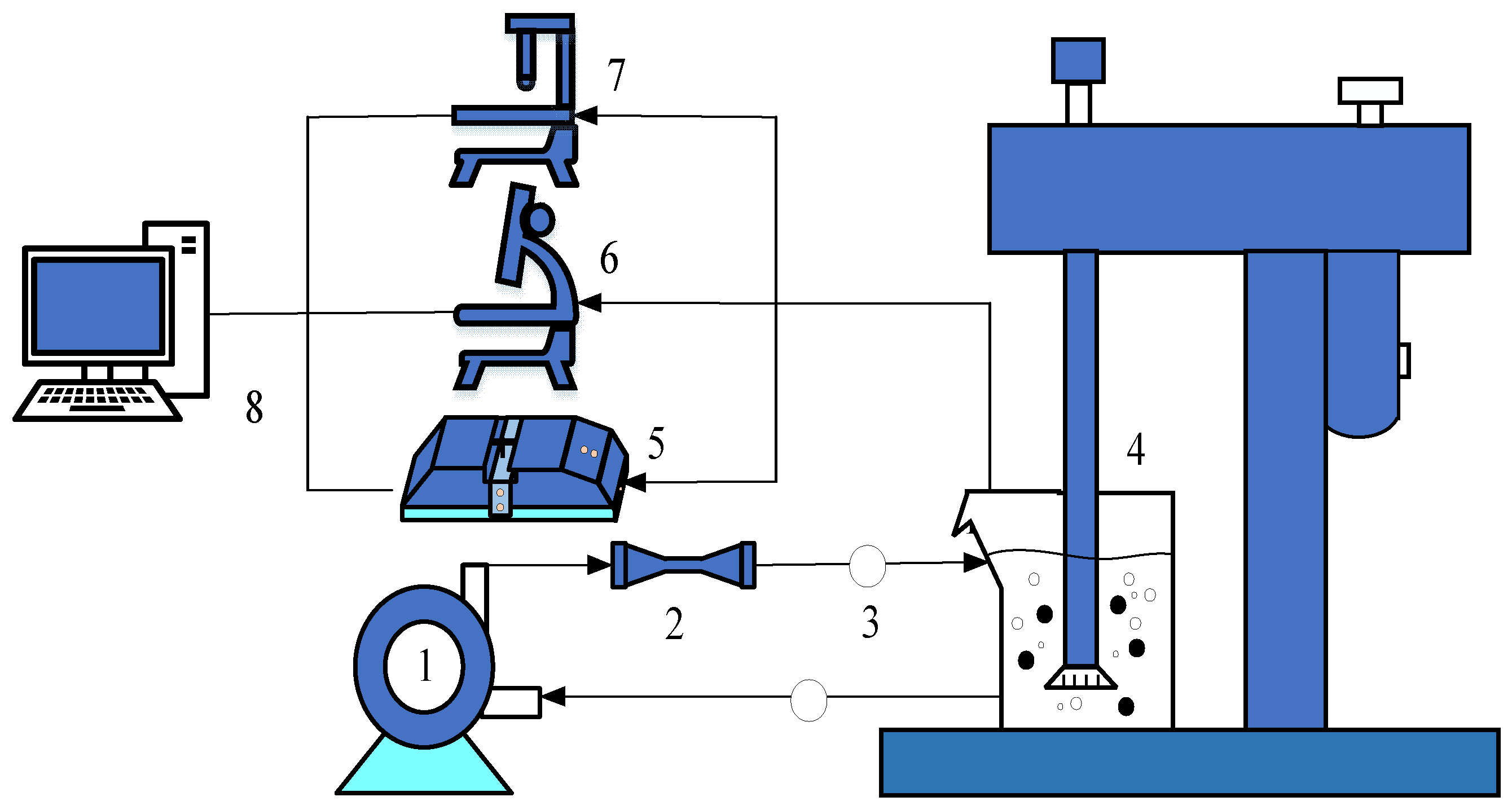
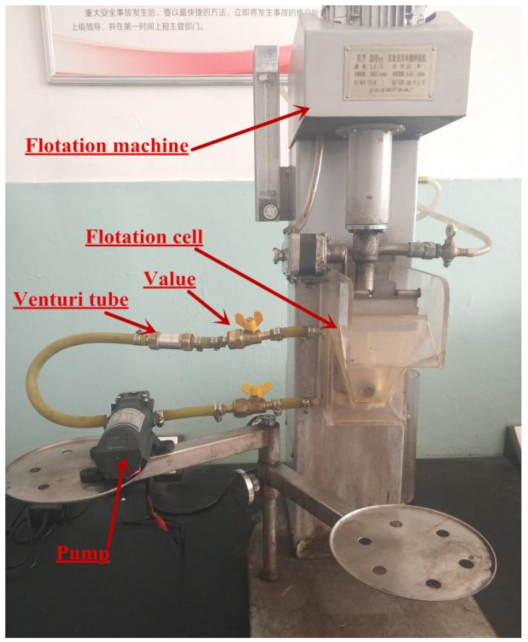
The HC-assisted flotation system is similar to the conventional one; the schematic diagram and real apparatus of the HC-assisted flotation system are shown in
Figure 2 and
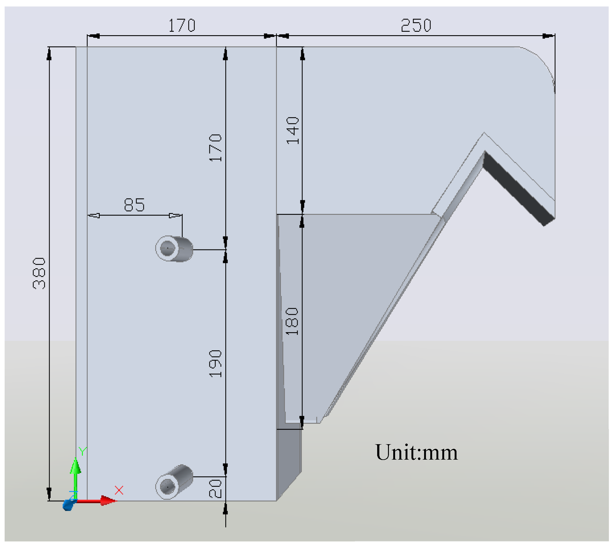
Figure 3, respectively. The specially designed flotation cell schematic diagram is given in
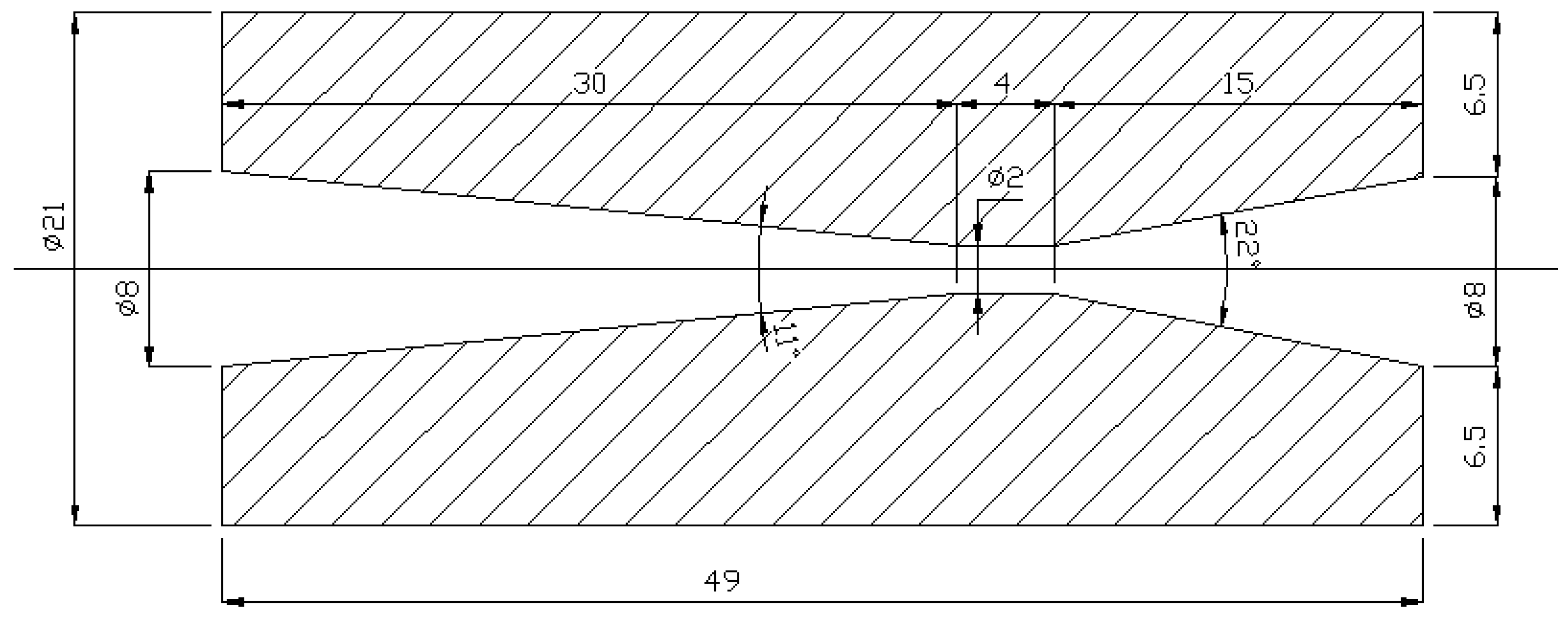
Figure 4. Two perspex tubes were installed on one side of the flotation cell. A venturi tube and pump were used for the HC treatment of slurry. The slurry was pumped through the venturi tube (geometric parameters are shown in
Figure 5) from the lower outlet and led back to the flotation cell through the higher inlet. The operating parameters of the tests are shown in
Table 3.
2.3. Laser Particle Size Analysis Tests
A laser particle size analyzer (Microtrac S3500, Microtrac Corporation, Montgomeryville, PA, USA) was used to determine bubble and collector size distribution in conventional and HC-assisted flotation conditions. A combination of 1 L of distilled water with 7.5 μL 2-Octyl alcohol was conditioned in the flotation machine at 1800 rpm and an air flow rate of 0.2 m3/h, with and without HC assistance, respectively. After 1 min, the solution was extracted for the size distribution tests. The collector size test was similar to the bubble size test; 1 L distilled water with 18.75 μL kerosene was agitated in the flotation cell at 1800 rpm for 1 min, with and without HC assistance, and then extracted for the size measurement.
2.4. Microscope Tests
Microscope tests were conducted to detect nanobubbles generated in the presence of HC; the procedure was similar to the bubbles size tests discussed in
Section 2.3, except for the residence time of 3 min to remove the large bubbles. A microscopy camera (LEICA DMC 4500, Leica Camera, Wetzlar, Germany) was used to observe the nanobubbles.
2.5. Contact Angle Tests
Contact angle tests were conducted using a contact angle meter (DSA 100, KRUSS GmbH, Hamburg, Germany). Flotation concentrate products of four flotation types were filtered, dried, and weighed for the contact angle tests. The static water drop method was used for the contact angle test. A 0.5 g sample was compressed using a tableting machine and placed in the sample stage; then, a drop of water (25 μL) was dropped on to the sample (the distance from tip to the sample was 1 cm). A digital camera was used to capture the images of the three-phase interface.
3. Results and Discussion
3.1. Effect of Hydrodynamic Cavitation (HC) on Particle Size Distribution
To investigate the variation in particle sizes of coal samples under HC, the size distributions of coal samples with HC under 0.5, 1, 1.5, 3, and 6 min were analyzed. Coal samples under cavitation treatment were screened and divided into five size fractions: −0.5 + 0.25, −0.25 + 0.125, −0.125 + 0.074, −0.074 + 0.045, and −0.045 mm.
Table 4 indicates particle size distribution variation under HC. With increase in cavitation time, the particle size of the coal sample tended to decrease, especially at +0.25 mm. At 6 min, the yield of +0.25 mm decreased from 24.99% to 20.65% and ash increased by 3.93%. The results show that it is easier for HC to break up coarse coal particles than other gangue minerals. For fine particles, the yield and ash content showed little change, when compared to raw coal. Hydrodynamic cavitation requires an energy input to create velocity difference of the liquid, and the high-speed liquid jet destroys solid surfaces and leads to breakage of particles [
21]. In consideration of optimum flotation size, medium-size coal particles generated by HC were found to be beneficial for flotation.
3.2. Flotation Results of Different Flotation Types with HC Assistance
The results for four flotation types (conventional flotation, hydrodynamic cavitation on conditioning stage (HCCS), hydrodynamic cavitation on separation stage (HCSS), and hydrodynamic cavitation on whole stage (HCWS)) at different collector dosages are shown in
Figure 6. It can be seen that, in the flotation without a collector, ash content decreases slightly with the assistance of HC. When the collector dosage increases, especially at 500 g/t, ash content is higher with the introduction of HC, which means that the HC-assisted flotation has better selectivity at lower collector dosages. Besides, all kinds of HC-assisted flotations have higher concentrate combustible recovery than conventional flotation. Compared to conventional flotation, concentrate combustible recovery with HCWS increases by about 6%, while HCCS and HCSS increase about 3%. The increment in concentrate combustible recovery of HCWS is close to the sum of HCCS and HCSS. The results, which are similar to that of previous studies, indicate that HC assistance is beneficial to the flotation process [
8,
16], HCCS and HCSS have similar flotation results, and HCWS showed the highest flotation performance improvement in comparison to the other two kinds of HC-assisted flotations.
3.3. Comparison of HC Time on Flotation Results
In consideration of the impact of longer HC treatment time on the flotation performance of HCWS, the influence of HC time in the conditioning stage on flotation performance was investigated. In conventional flotation, before the flotation agents are added, there is a 2-min agitation process to disperse and moisten the coal sample. The collector is then added to the slurry and left for 1 min to enhance the adsorption of the collector on the coal particles. Each of these conditioning parts were thus studied in the presence and absence of HC, respectively; when the time of one conditioning part was changed, the other conditioning part was found to be consistent with conventional flotation.
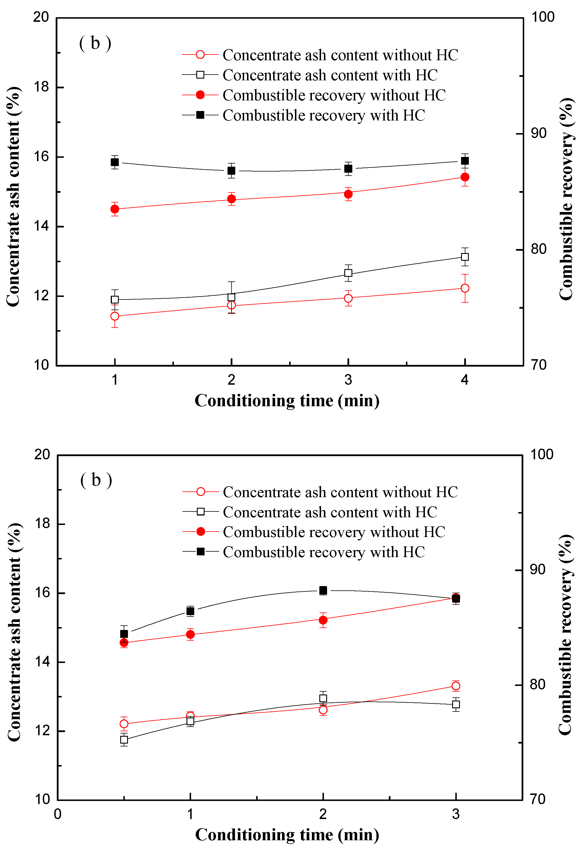
Figure 7a,b depict the experimental results of the non-collector conditioning time and collector conditioning time, respectively.
As shown in
Figure 7a, the ash contents of the concentrates increased with increase in conditioning time, in both conventional flotation and HC-assisted flotation. However, with the same conditioning time, concentrate combustible recovery with HC was found to be higher than that of conventional flotation, especially at a shorter time. In other words, HC has a stronger mixing effect, which promotes mixing efficiency and reduces conditioning time.
With respect to the effect of conditioning time on flotation performance in the presence of a collector,
Figure 7b shows that, in conventional flotation, with increase in agitation time using a reagent, ash content and combustible recovery was found to increase slightly—from 0.5 to 3 min. However, in the presence of HC, ash content and combustible recovery both increased with rise in conditioning time, and reached a peak at 2 min. It is to be noted that—except for the increase in combustible recovery—better flotation performance with HC was displayed with reduced ash content. When compared to conventional flotation tests, it is clear that HC can reduce conditioning time; however, excessive HC-assisted conditioning time does not enhance flotation efficiency.
3.4. Comparison of the Results of Flotation Kinetic Tests
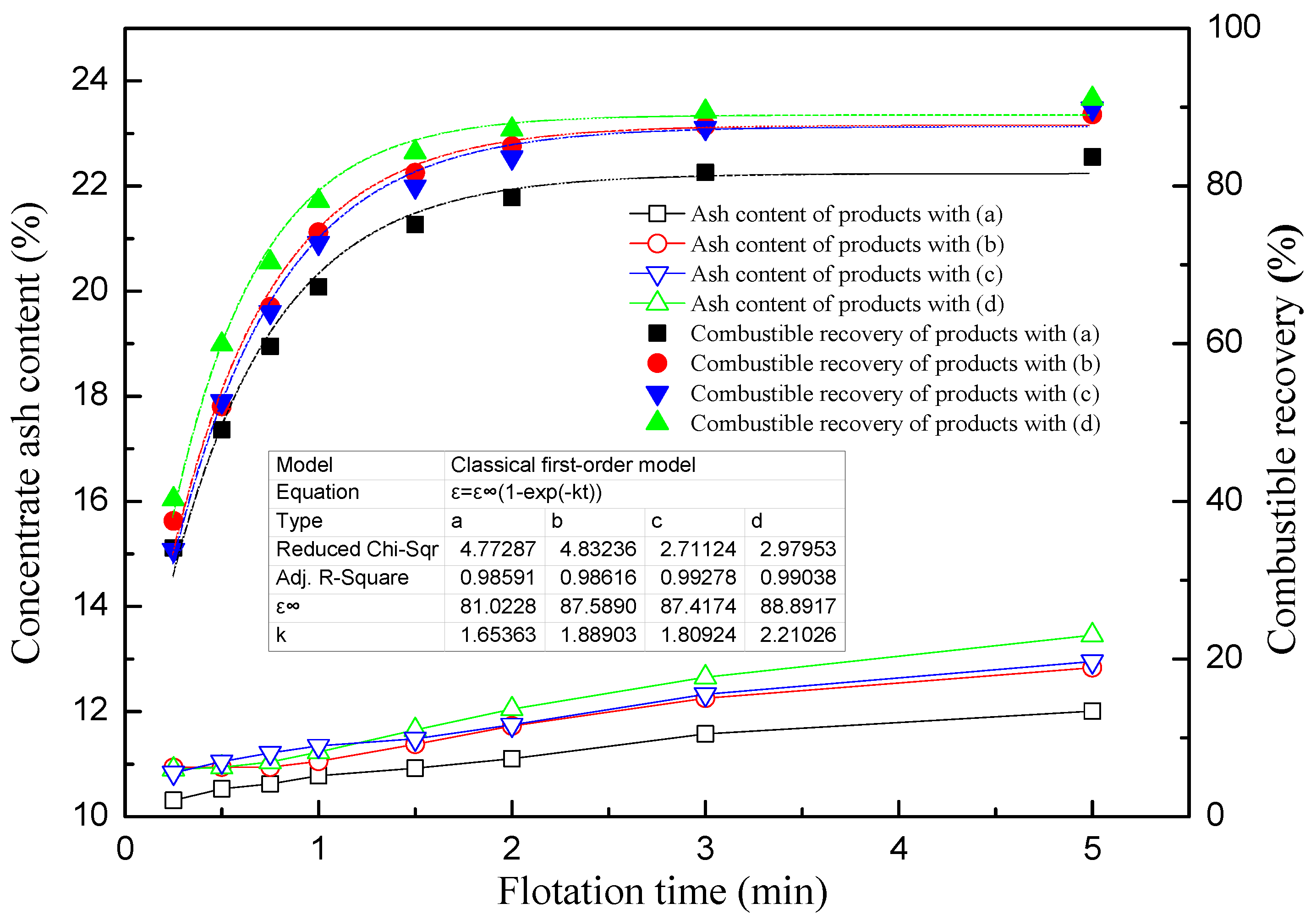
Flotation kinetic tests were carried out to investigate the effect of different cavitation assistance methods on flotation rate. The flotation rate results conform to the classical first order model, given by Equation (1):
where
ε represents the combustible recovery, %;
k represents the flotation rate constant;
ε∞ represents the theoretical maximum combustible recovery, %;
t represents the flotation time, min.
As shown in
Figure 8, the flotation rate of conventional flotation, HCCS, HCSS, and HCWS are 1.65, 1.89, 1.81, and 2.21, respectively. When compared to conventional flotation, the flotation constant rate of HCCS, HCSS and HCWS was found to increase by 14.24%, 9.41%, and 33.66%, respectively. The combination of HCCS and HCSS has a higher flotation rate than each approach alone. It is generally believed that the formation of nanobubbles on the hydrophobic particle surface with the help of HC leads to the agglomeration of fine particles and an increase in flotation rate. For HCSS, the reduction in flotation bubbles, including the generation of nanobubbles by HC, increases the collision probability of particles and bubbles, leading to an improvement in flotation rate. It is assumed that there is cooperation between the two mechanisms.
3.5. Bubble Size Distribution with HC Assistance
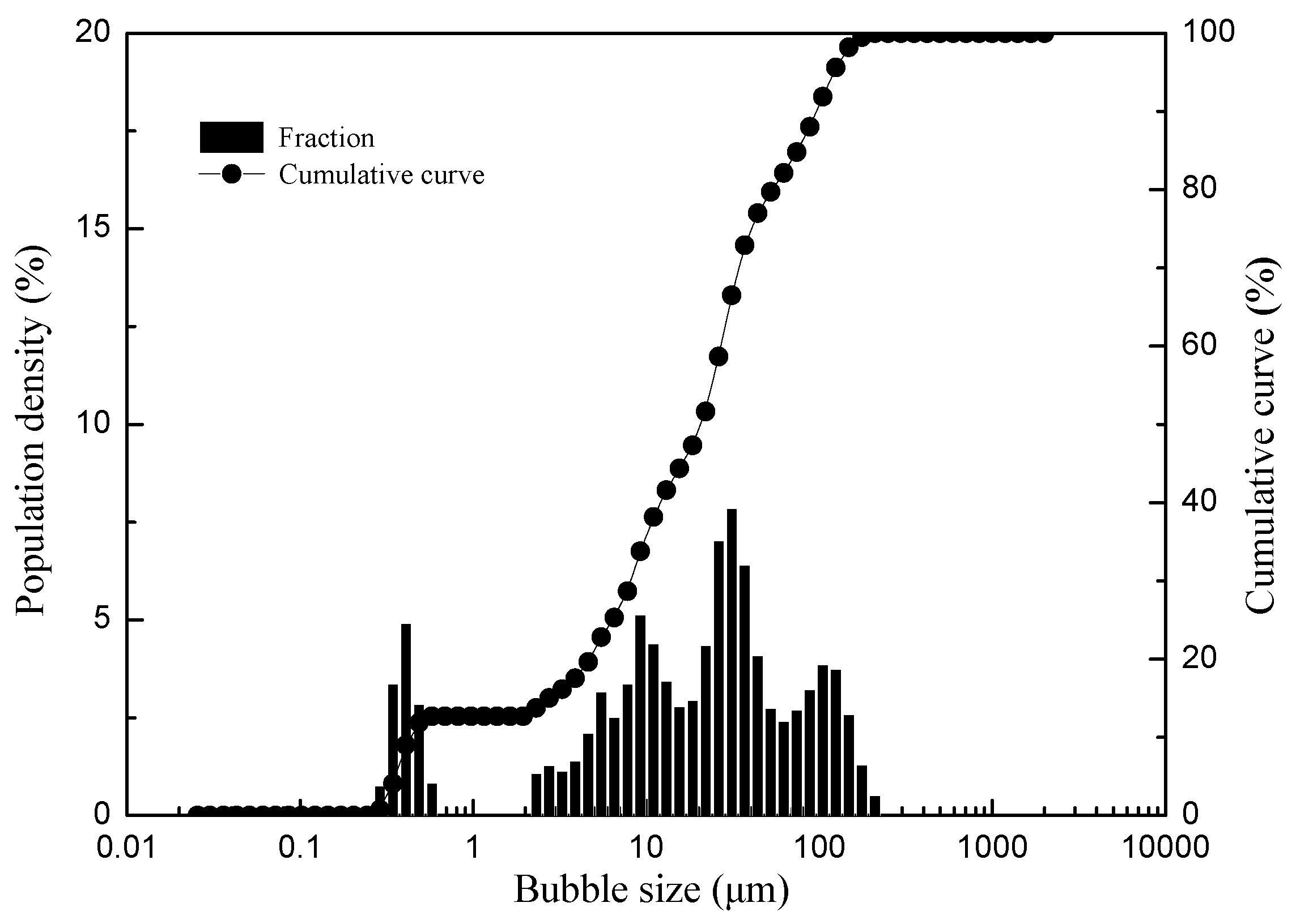
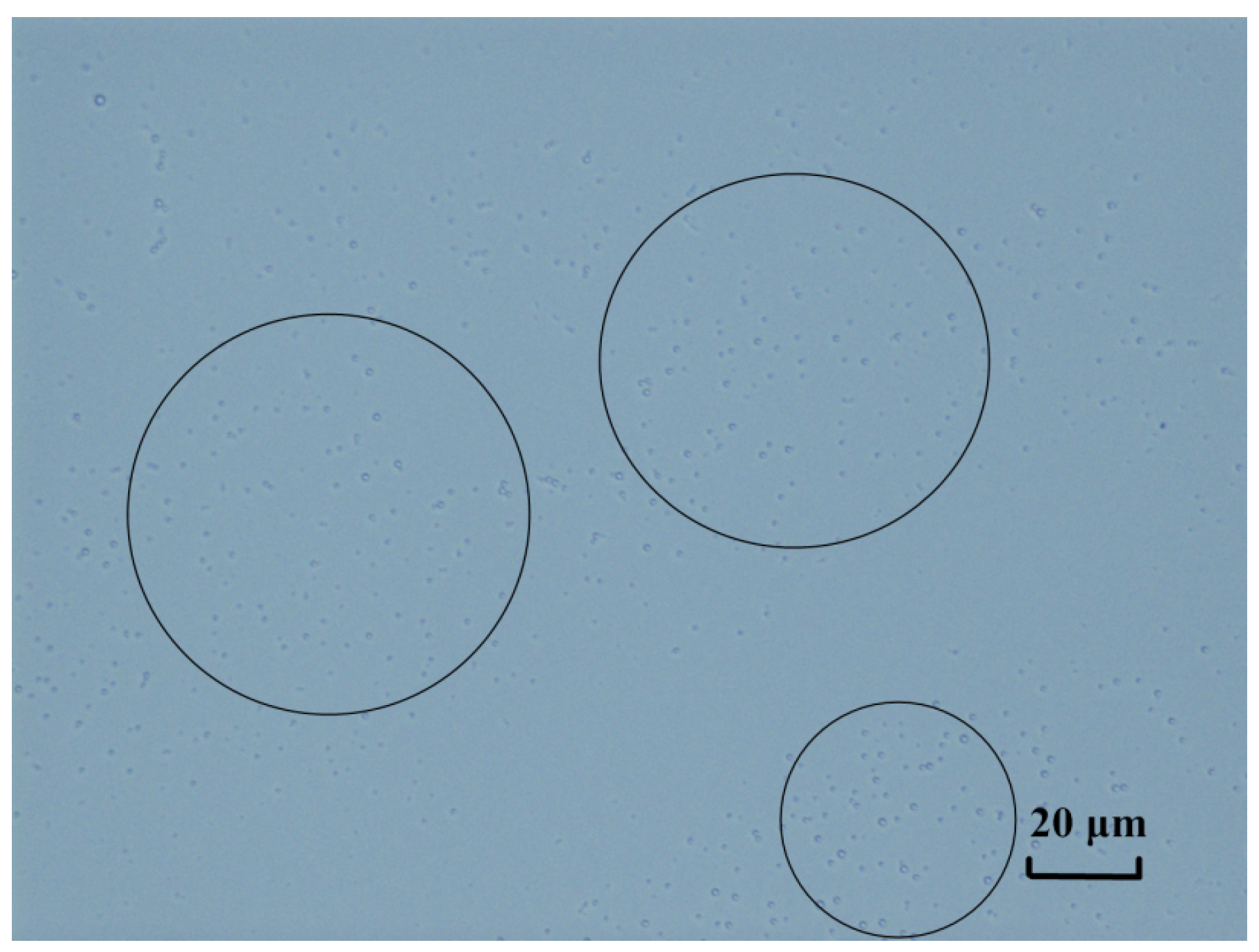
Figure 9 and
Figure 10 show bubble size distribution and nanobubble image under HC assistance, respectively. It can be clearly seen that micro-nanobubbles generated in the presence of HC lead to a decrease in bubble size. The solution under flotation machine agitation cannot be detected with a laser size analyzer and microscope camera. Considering the stability of nanobubbles [
22], it is believed that nanobubbles can hardly be generated in conventional flotation. With massive air gas injection in the flotation separation stage, the reduction in bubble size causes a larger number of bubbles and greater collision probability between the coal particles and the bubbles. In addition, the nanobubbles generated by HC adsorb on the hydrophobic surface and form fine particle aggregation, thus improving flotation performance [
9,
20].
3.6. Comparison of Collector Size Distribution
Figure 11 depicts the comparison of size distribution of kerosene (a collector) between conventional agitation and the HC-assisted method. The D
10, D
50, and D
90 of the size fractions of kerosene under conventional agitation were found to be 33.98, 72.41, and 174.05 μm, respectively. While, for HC assistance, the D
10, D
50, and D
90 of the size fractions decreased to 5.05, 12.30, and 22.92 μm, respectively. This demonstrates that HC has a more significant dispersion effect on kerosene than flotation machine agitation. The large pressure difference between the inlet and outlet of the throat causes high liquid speed and hydrodynamic stress; meanwhile, shock waves and micro-jets disperse the kerosene drops in the liquid. With the decrease in kerosene drops, a larger specific surface area and higher amount of kerosene drops results in higher collision and attachment probabilities between the kerosene and the coal particles, which is beneficial for coal flotation.
3.7. Comparison of Product Contact Angles
According to Young’s equation, a larger contact angle means greater hydrophobicity. As dry flotation products were being tested, the main factors affecting the samples’ hydrophobicity were the surface properties of the particles themselves and collector adsorption, not the nanobubbles generated by the HC.
Figure 12 shows the contact angles of the concentrates in different flotation modes. Compared to non-collector flotation, the contact angle of the concentrate in conventional flotation increased by about 10°. However, in the presence of HCCS, a bigger concentrate contact angle was obtained, which means that more collector was adsorbed on the surface of the coal particles; the results relate to size reduction in the collector, as is shown in
Figure 10. However, the contact angle of the concentrate under HCSS showed an obvious decrease, when compared to the conventional one, and the value is similar to the results of conventional flotation without a collector. It is assumed that the adsorption behavior of the collector was disturbed by the HCSS with a large gas content. In view of
Figure 6,
Figure 9 and
Figure 10, the reasons why HCWS promotes flotation performance are probably the decrease in size of the flotation bubbles and the existence of nanobubbles. On the other hand, HCWS has a middle contact angle value between HCCS and HCSS, which might be a consequence of HCCS and HCSS acting together.
Based on the above results, a possible mechanism of HC-assisted flotation is proposed, as shown in
Figure 13. The effect of HC on the improvement of flotation performance is different for the conditioning and separation stages. HCCS increases the dispersity and efficiency of the collector, while micro-nanobubbles generated by HC play a major role in HCSS. The combination of HCCS and HCSS, which offers both advantages, leads to higher separation efficiency.
4. Conclusions
HC—including HCCS, HCSS, and HCWS—promotes coal flotation performance to a great extent, in comparison to conventional flotation. HCWS offers the highest combustible recovery and flotation rate of the concentrate over HCCS and HCSS. It is easier for coarse coal particles to be broken in the presence of HC. HCCS decreases the pretreatment time and enhances the flotation effect, but excessive HC conditioning time is not shown to have better flotation results. Furthermore, the extension of HC time on the separation stage cannot improve flotation performance. The reduction in size of the collector caused by HC contributes to the adsorption of reagents on the surface of coal particles with HCCS. However, during the separation stage, the introduction of HC may cause desorption of the collector from the surface of the coal particles, decrease in size of the bubbles. Micro-nanobubbles are another factor enhancing flotation performance.
Author Contributions
Conceptualization, H.W.; data curation and formal analysis, H.H.; methodology, A.L; writing—original paper preparation, review, and editing, H.H.; visualization and validation, A.L.; supervision, H.W.; funding acquisition, A.L. All authors have read and agreed to the published version of the manuscript.
Funding
This research was funded by the National Natural Science Foundation of China (No.51704208).
Acknowledgments
The authors would like to thank the Academic Editor for handing this paper and reviewers for their helpful comments and suggestions.
Conflicts of Interest
The authors declare no conflict of interest. The funders played no role in the design of the study, collection, analyses of data, writing of the manuscript, or decision to publish the results.
References
- Kirjavainen, V.M. Review and analysis of factors controlling the mechanical flotation of gangue minerals. Int. J. Miner. Process. 1996, 46, 21–34. [Google Scholar] [CrossRef]
- Jameson, G.J. New directions in flotation machine design. Miner. Eng. 2010, 23, 835–841. [Google Scholar] [CrossRef]
- Bakalarz, A.; Duchnowska, M.; Pawlos, W. Influence of hydrodynamics on preflotation process in flotation machine. Miner. Metall. Proc. 2018, 35, 19–23. [Google Scholar] [CrossRef]
- Fan, M.; Tao, D.; Honaker, R.; Luo, Z. Nanobubble generation and its application in froth flotation (part I): Nanobubble generation and its effects on properties of microbubble and millimeter scale bubble solutions. Min. Sci. Technol. 2010, 20, 1–19. [Google Scholar] [CrossRef]
- Xiong, Y.; Peng, F. Optimization of cavitation venturi tube design for pico and nano bubbles generation. Int. J. Min. Sci. Technol. 2015, 25, 523–529. [Google Scholar] [CrossRef]
- Ziaeddin, P.; Bahram, R.; Mohammad, N. Effective parameters on generation of nanobubbles by cavitation method for froth flotation applications. Physicochem. Probl. Miner. Process. 2017, 53, 920–942. [Google Scholar]
- Etchepare, R.; Oliveira, H.; Nicknig, M.; Azevedo, A.; Rubio, J. Nanobubbles: Generation using a multiphase pump, properties and features in flotation. Miner. Eng. 2017, 112, 19–26. [Google Scholar] [CrossRef]
- Zhou, Z.A.; Xu, Z.; Finch, J. On the role of cavitation in particle collection during flotation-A critical review II. Miner. Eng. 2009, 22, 419–433. [Google Scholar] [CrossRef]
- Zhou, W.G.; Chen, H.; Ou, L.M.; Shi, Q. Aggregation of ultra-fine scheelite particles induced by hydrodynamic cavitation. Int. J. Miner. Process. 2016, 157, 236–240. [Google Scholar] [CrossRef]
- Nazari, S.; Shafaei, S.Z.; Gharabaghi, M.; Ahmadi, R.; Shahbazi, B.; Maoming, F. Effects of nanobubble and hydrodynamic parameters on coarse quartz flotation. Int. J. Miner. Process. 2018, 29, 289–295. [Google Scholar] [CrossRef]
- Ahmadi, R.; Khodadadi, D.A.; Abdollahy, M.; Fan, M. Nano-microbubble flotation of fine and ultrafine chalcopyrite particles. Int. J. Min. Sci. Technol. 2014, 24, 559–566. [Google Scholar] [CrossRef]
- Nazari, S.; Shafaei, S.Z.; Shahbazi, B.; Chehreh Chelgani, S. Study relationships between flotation variables and recovery of coarse particles in the absence and presence of nanobubble. Colloids Surf. A. 2018, 559, 284–288. [Google Scholar] [CrossRef]
- Zhou, W.G.; Qu, L.M.; Shi, Q.; Feng, Q.M.; Chen, H. Different Flotation Performance of Ultrafine Scheelite under Two Hydrodynamic Cavitation Modes. Minerals 2018, 8, 264. [Google Scholar] [CrossRef]
- Xiong, Y. Bubble Size Effects in Coal Flotation and Phosphate Reverse Flotation Using a Pico-Nano Bubble Generator; West Virginia University: Morgantown, WV, USA, 2014. [Google Scholar]
- Sobhy, A.; Tao, D. Effects of Nanobubbles on Froth Stability in Flotation Column. Int. J. Coal Prep. Util. 2018, 1–16, 183–198. [Google Scholar] [CrossRef]
- Sobhy, A.; Tao, D. Nanobubble column flotation of fine coal particles and associated fundamentals. Int. J. Miner. Process. 2013, 124, 109–116. [Google Scholar] [CrossRef]
- Peng, F.F.; Xiong, Y. Pico-nano bubble column flotation using static mixer-venturi tube for Pittsburgh No. 8 coal seam. Int. J. Min. Sci. Technol. 2015, 25, 347–354. [Google Scholar] [CrossRef]
- Fan, M.; Tao, D.; Honaker, R.; Luo, Z. Nanobubble generation and its applications in froth flotation (part IV): Mechanical cells and specially designed column flotation of coal. Int. J. Min. Sci. Technol. 2010, 20, 317–338. [Google Scholar] [CrossRef]
- Fan, M.; Tao, D.; Honaker, R.; Luo, Z. Nanobubble generation and its applications in froth flotation (part II): Fundamental study and theoretical analysis. Int. J. Min. Sci. Technol. 2010, 20, 159–177. [Google Scholar] [CrossRef]
- Zhou, W.; Niu, J.; Xiao, W.; Qu, L. Adsorption of bulk nanobubbles on the chemically surface-modified muscovite minerals. Ultrason. Sonochem. 2019, 51, 31–39. [Google Scholar] [CrossRef]
- Momber, A.W. Aggregate liberation from concrete by flow cavitation. Internal. J. Miner. Process. 2004, 74, 177–187. [Google Scholar] [CrossRef]
- Azevedo, A.; Etchepare, R.; Calgaroto, S.; Rubio, J. Aqueous dispersions of nanobubbles: Generation, properties and features. Miner. Eng. 2016, 94, 29–37. [Google Scholar] [CrossRef]
Figure 1.
XRD patterns of the coal sample.
Figure 1.
XRD patterns of the coal sample.
Figure 2.
Schematic diagram of the experimental apparatus: (1) pump; (2) venturi tube; (3) valve; (4) flotation machine; (5) laser particle size analyzer; (6) microscope; (7) contact angle meter; (8) computer.
Figure 2.
Schematic diagram of the experimental apparatus: (1) pump; (2) venturi tube; (3) valve; (4) flotation machine; (5) laser particle size analyzer; (6) microscope; (7) contact angle meter; (8) computer.
Figure 3.
HC-assisted flotation system.
Figure 3.
HC-assisted flotation system.
Figure 4.
Diagram of the designed special flotation cell.
Figure 4.
Diagram of the designed special flotation cell.
Figure 5.
Structure parameters of the venturi tube.
Figure 5.
Structure parameters of the venturi tube.
Figure 6.
Comparison of the flotation results of different hydrodynamic cavitation (HC) flotation types at different collector dosages (a) 0 g/t, (b) 250 g/t, and (c) 500 g/t.
Figure 6.
Comparison of the flotation results of different hydrodynamic cavitation (HC) flotation types at different collector dosages (a) 0 g/t, (b) 250 g/t, and (c) 500 g/t.
Figure 7.
Effect of HC time on the flotation results at different conditioning stages: (a) without a collector, and (b) with a collector.
Figure 7.
Effect of HC time on the flotation results at different conditioning stages: (a) without a collector, and (b) with a collector.
Figure 8.
Flotation kinetics results in four types of flotation (a) Conventional flotation, (b) conditioning stage (HCCS), (c) separation stage (HCSS), and (d) whole stage (HCWS).
Figure 8.
Flotation kinetics results in four types of flotation (a) Conventional flotation, (b) conditioning stage (HCCS), (c) separation stage (HCSS), and (d) whole stage (HCWS).
Figure 9.
Size distribution of bubbles under HC.
Figure 9.
Size distribution of bubbles under HC.
Figure 10.
Nanobubbles in the solution with HC assistance.
Figure 10.
Nanobubbles in the solution with HC assistance.
Figure 11.
Size fraction of the collector: (a) Conventional agitation; (b) HC-assisted agitation.
Figure 11.
Size fraction of the collector: (a) Conventional agitation; (b) HC-assisted agitation.
Figure 12.
Contact angle of flotation products for different flotation types: (a) Conventional flotation without collector; (b) Conventional flotation with collector; (c) HCCS; (d) HCSS; and (e) HCWS.
Figure 12.
Contact angle of flotation products for different flotation types: (a) Conventional flotation without collector; (b) Conventional flotation with collector; (c) HCCS; (d) HCSS; and (e) HCWS.
Figure 13.
Schematic diagram of the flotation enhancement of HCCS, HCSS, and HCWS.
Figure 13.
Schematic diagram of the flotation enhancement of HCCS, HCSS, and HCWS.
Table 1.
Proximate analysis of the coal sample.
Table 1.
Proximate analysis of the coal sample.
| Mad(%) | Vad (%) | FCad (%) | Aad (%) |
|---|
| 1.15 | 28.21 | 46.03 | 24.59 |
Table 2.
Particle size distribution of the coal sample.
Table 2.
Particle size distribution of the coal sample.
| Size Fraction (mm) | Weight (%) | Ash Content (%) |
|---|
| −0.5 + 0.25 | 24.99 | 23.51 |
| −0.25 + 0.125 | 21.19 | 22.32 |
| −0.125 + 0.074 | 12.72 | 22.65 |
| −0.074 + 0.045 | 9.68 | 22.21 |
| −0.045 | 31.42 | 28.51 |
| Total | 100.00 | 24.59 |
Table 3.
Cavitation conditions and operating parameter values used for the flotation tests.
Table 3.
Cavitation conditions and operating parameter values used for the flotation tests.
| Operating Parameters | Pump Flow (L/min) | Pulp Density (g/L) | Impeller Speed (rpm) | Air Flow Rate (m3/h) | Kerosene (g/t) | Sec-Octyl Alcohol (g/t) |
|---|
| Value | 3 | 60 | 1800 | 0.2 | 250 | 100 |
Table 4.
Comparison of screening results of coal samples under different cavitation time.
Table 4.
Comparison of screening results of coal samples under different cavitation time.
| Size Fraction (mm) | Raw Coal | Cavitation Time (min) |
|---|
| 0.5 | 1 | 1.5 | 3 | 6 |
|---|
| Yield (%) | Ash (%) | Yield (%) | Ash (%) | Yield (%) | Ash (%) | Yield (%) | Ash (%) | Yield (%) | Ash (%) | Yield (%) | Ash (%) |
|---|
| –0.5 + 0.25 | 24.99 | 23.51 | 24.57 | 23.42 | 24.47 | 24.53 | 24.12 | 24.52 | 22.64 | 26.39 | 20.65 | 27.44 |
| –0.25 + 0.125 | 21.19 | 22.32 | 21.35 | 22.52 | 21.64 | 22.64 | 22.11 | 23.27 | 21.89 | 23.54 | 22.89 | 22.87 |
| –0.125 + 0.074 | 12.72 | 22.65 | 12.87 | 22.02 | 13.01 | 23.01 | 12.56 | 24.81 | 13.18 | 22.43 | 13.43 | 23.18 |
| –0.074 + 0.045 | 9.68 | 22.21 | 9.34 | 23.52 | 9.56 | 23.05 | 9.55 | 25.62 | 9.45 | 24.97 | 9.70 | 25.16 |
| –0.045 | 31.42 | 28.51 | 31.87 | 28.96 | 31.32 | 28.67 | 31.66 | 28.67 | 32.84 | 28.76 | 33.33 | 28.49 |
| Total | 100 | 24.59 | 100 | 24.82 | 100 | 25.08 | 100 | 25.70 | 100 | 25.89 | 100 | 25.95 |
© 2020 by the authors. Licensee MDPI, Basel, Switzerland. This article is an open access article distributed under the terms and conditions of the Creative Commons Attribution (CC BY) license (http://creativecommons.org/licenses/by/4.0/).


