Article

Waste Slag from Heating Plants as a Partial Replacement for Cement in Mortar and Concrete Production. Part I—Physical–Chemical and Physical–Mechanical Characterization of Slag

by
Andrijana Nedeljković
1,
Marija Stojmenović
1,
Jelena Gulicovski
1,
Nenad Ristić
2,
Sonja Milićević
3,
Jugoslav Krstić
4 and
Milan Kragović
1,*
1
“Vinča” Institute of Nuclear Sciences, National Institute of the Republic of Serbia, University of Belgrade, 22-24 Mike Petrovića Alasa, 11351 Belgrade, Serbia
2
Faculty of Civil Engineering and Architecture, University of Niš, 18000 Niš, Serbia
3
Institute for Technology of Nuclear and Other Mineral Raw Materials, Franše d’Eperea 86, 11000 Belgrade, Serbia
4
University of Belgrade, Institute of Chemistry, Technology and Metallurgy, National Institute, Centre for Catalysis and Chemical Engineering, 11000 Belgrade, Serbia.
*
Author to whom correspondence should be addressed.
Minerals 2020, 10(11), 992; https://doi.org/10.3390/min10110992
Submission received: 10 October 2020 / Revised: 3 November 2020 / Accepted: 6 November 2020 / Published: 9 November 2020

Abstract

:
Numerous factors influence the complexity of environmental and waste management problems, and the most significant goal is the reuse of materials that have completed their “life cycle” and the reduction in the use of new resources. In order to reduce impact of waste slag on the environment, in the present study, waste slag, generated in heating plants after lignite combustion, was characterized in detail and tested for application as a replacement for cement in mortar or concrete production. For physical–chemical characterization of slag, different experimental and instrumental techniques were used such as chemical composition and determination of the content of heavy metals, investigation of morphological and textural properties, thermal analysis, X-ray, and infrared spectroscopy. Physical–mechanical characterization of slag was also performed and included determination of activity index, water requirement, setting time and soundness. A leaching test was also performed. Presented results show that waste slag may be used in mortar and concrete production as a partial cement replacement, but after additional combustion at 650 °C and partial replacement of slag with silica fume in the minimal amount of 12%. The maximal obtained cement replacement was 20% (17.8% slag and 2.2% of silica fume).

1. Introduction

Coal is the energy source with the highest percentage of estimated fossil fuels (over 65%), with more evenly distributed deposits in the world than oil and gas. The USA, Russia, Australia, China, India, Indonesia, Germany, Ukraine, Poland, and Kazakhstan are some of the largest coal producers in the world [1]. Coal is a widespread fossil fuel used around the world. About 23% of the primary energy demand and 39% of electricity is obtained from coal. Due to the decline in oil and gas reserves, significant use of coal is expected to increase in the future. Today, about 40% of the world’s total energy is produced from coal, and it is expected that this situation will remain in the future [2].
In general, there are various methods for the classification of coal, including the carbon content, origin, purpose, age, thermal power, and other properties. Thus, according to the carbon content, there are the following types of coal: (1) anthracite, or “hard coal”, contains carbon in the range of 86–97%. It is characterized by a brittle texture and lustrous sheen and due to the high heat value it is mainly used in industrial settings and the metal industry; (2) bituminous coal, often called “soft coal”, possesses a slightly lower content of carbon in comparison to anthracite (45–86%) and is mostly used for electricity and steel production; (3) sub-bituminous coal has a carbon content of 35–45% and its primary field of application is electricity generation; (4) lignite (“brown coal”) has a carbon content of 25–35%. Its characteristics are high moisture content, which sometimes reaches 66%, and crumbly texture, and it is often used for the generation of electricity [3]. It is also known as medium-calorie coal and due to its application and quantity, it represents an exceptional potential in energy terms. Although it contains a relatively high amount of moisture, the thermal power of lignite is relatively high—ranging from 10 to 20 MJ/kg. The combustible part of lignite consists of solid organic matter and volatiles, while moisture and ash are the non-combustible part. The non-combustible part, in addition to fly ash, which represents about 85–95% of the total amount of ash, contains slag in the amount of about 10% [4]. If we take into account that the world’s annual consumption of lignite is more than 1600 million tons [5], it practically means that the production of fly ash in the world is more than hundreds of millions tons [5,6], while the calculated amount of slag is more than 160 million tons. In Serbia, the annual production of fly ash is around six million tons, and slag 500–600 thousand tons [7].
From a chemistry standpoint, coal ash (or shorter ash) is defined as a solid non-combustible residue that remains after coal annealing. Thus, several types of ash can be distinguished as follows: slag (bottom ash), the primary non-combustible residue extracted from the bottom of the boiler; boiler ash, larger classes of which are extracted from the boiler together with the flue gases and fly ash, the finest class, separated from the boiler with flue gases [8].
Ash and slag obtained as waste materials by incomplete combustion of coal such as lignite in power or heating plants usually contain different, very toxic, microelements such as arsenic, cadmium, chromium, copper, manganese, nickel, lead, selenium, zinc as well as their compounds, which are very harmful for the environment, natural resources and hence may affect the life and health of humans [9,10,11]. According to the EU’s rule book “List of Waste” [12] as well as Serbia’s “Rules on the manner of handling waste that have the characteristics of hazardous substance” [13], waste material that contains heavy metals and other hazardous substances must be classified as hazardous waste.
In most countries, including Serbia, there are appropriate regulations that necessitate stricter controls and additional measures for securing, disposing and transporting generated hazardous waste as well as additional financial costs for the companies to pay the state in the view of additional taxes [14]. However, despite financial costs, the most significant problem is the impact of such waste on nature and the environment. Waste material from landfills can relatively easily pollute the environment by scattering both air and soil. as well as water systems and resources and thereby directly pollute and endanger the health of animals and plants, but the most significant concern is the health and food of humans. To reduce the harmful impacts on the environment, as well as to avoid financial costs for the companies, it is of particular importance to find useful value in such a waste. In this way, the benefits may be multiple—environmental and financial—so all aspects of green chemistry and circular economy would be satisfied.
The potential application of fly ash in industries is fairly well described in the literature [15,16,17,18,19,20]. However, practical applications of slag are still not well described and sufficiently examined. The slag particles have large dimensions, and because of this they may be used as an aggregate, in road construction and in the brick industry, as well as in the production of so-called slag-blocks. Additionally, in the EU member states, slag is intensively and increasingly used to encapsulate landfills [21,22]. Different authors have investigated the application of the blast furnace slag, which is generated in industries as a partial cement replacement. Adu-Amankwah et al. [23] investigated the influence of limestone on the hydration of ternary slag cements. In their study, mixes with different amounts of cement–slag/quartz–limestone/quartz–anhydrite were prepared and tested. The amount of slag used was expressed as slag/quartz content, which was in the range of ~28–47%. In the study of the Sum et al. [24], optimization of gypsum and slag content in blended cement containing slag was investigated. For these experiments, blast furnace slag was also used. In this study, different amounts of gypsum (0–40%), slag (60–100%) and clinker (0–40%) were mixed with Portland cement. Authors concluded that a high cement strength in the ternary slag–gypsum–clinker system may be obtained for 10% of gypsum, 20–40% of clinker and 60–75% of slag as well as for 10–25% of gypsum, less than 5% of clinker and 70–85% of slag. In the study of the Yoon et al. [25], blast furnace slag-blended Portland cement was used and tested for cobalt (Co) immobilization. In this study, authors replaced 0–70% of the cement with blast furnace slag. Their results show that regarding the retention of cobalt ions (Co2+), retention increases with increasing the slag content in the mixes and the best results were obtained for cement replacement of 70%. However, the amount of slag that is obtained and already presented in the landfills is significantly higher than actual needs, and therefore there is a need for new research studies that could enable or provide guidelines for the use of slag in other industries. It is important to emphasize that the slag obtained from different sources (blast furnaces, hitting plants, etc.) possess different chemical compositions and thus potential application for all of them must be checked, investigated, and proven. From the aspect of practical application, it is very important that the use of slag has no negative effects on the environment, only positive effects, which are reflected in the protection of natural aggregates, reduction of CO2 emissions, energy savings and, above all, reduction in waste material.
Due to its rough particles (sizes between sand and gravel), which have a glass structure and make it convenient to be used to replace natural aggregates (such as sand, gravel, crushed granite, etc.), potential practical application of slag in the cement industry was investigated in this study. The starting waste slag was characterized in detail and solutions were proposed to eliminate the defects of the slag from the aspect of application in the cement industry, and finally, the physical–mechanical characterizations of the obtained slag–Portland cement mixtures were made.

2. Materials and Methods

2.1. Sampling

The waste slag was sampled from landfill of a heating plant located in Valjevo, Serbia. The slag was obtained during combustion of lignite. The samples were taken from six different places at the landfill from three different depths, 30 samples in total. After sampling, the samples were dried at 105 °C for 2 h and homogenized. Homogenized slag samples were crushed, ground and sieved so the size of the grain and the particles were 100% below 63 µm before analysis.
Portland cement (CEM I 42.5R) was bought from the company CRH, Popovac, Serbia. Silica fume was bought from the company “Sika”.

2.2. Characterization

Determination of the chemical composition and heavy metal content in slag was obtained with classical chemical analysis [26], using the atomic absorption spectrophotometer AAnalyst 300 (Perkin Elmer, Waltham, MA, USA) and the spectrophotometer Specol 1300 (Analytic Jena, Wegberg, Germany), using standard and internally developed methods.
Simultaneous non-isothermal thermogravimetric analysis (TGA) and differential thermal analysis (DTA) were used for testing the thermal properties of the slag and the Portland cement. For measuring, a Setaram Setsys Evolution 1750 instrument (Setaram, Lion, France) was used. Measuring was performed in the temperature range of 25 to 1000 °C with a heating rate of 10 min−1 in an air atmosphere, with a flow of 16 cm3 min−1. The mass of the sample was 15 mg.
The Sorptomatic 1990 Thermo Finnigan device (Thermo Fisher, Waltham, MA, USA) was used to measure the textural properties of the slag. The nitrogen adsorption–desorption isotherms were obtained by adsorption at −196 °C. Firstly, the slag was degassed at room temperature for 1 h and then, under the same residual pressure, for 16 h at 110 °C. For analyzing the isotherms, Software ADP Version 5.13 Thermo Electron (Thermo Fisher, Waltham, MA, USA) was used. The Brunauer–Emmett–Teller (BET) method was used for determination of the specific surface area (SBET) of the slag [27]. The micropore volume (Vmic-DR) was determined by application of the Dubinin–Radushkevich (DR) equation on the nitrogen adsorption isotherms [28], while the Dollimore and Heal (DH) method [29] was used for measuring the mesopore volume (Vmeso).
The structural properties and the composition of the crystal phase of the slag and Portland cement were determined by Roentgen X-ray diffraction analysis (XRD). For XRD analysis, a PHILIPS PW-1710 X-ray diffractometer (Philips, Amsterdam, Netherlands) with a scintillation counter and a curved graphite monochromator was used. The measuring was performed at room temperature at 0.02°/s, in the range of 4–65° 2θ. A voltage of 40 kV and a current of 30 mA was used, while 1° and 0.1 mm slits were used for the direction of the primary and diffracted beams.
The field emission scanning electron microscopy (FESEM) and the TESCAN Mira3 XMU instrument at 20 kV (Tescan, Brno–Kohoutovice, Czech Republic) were used for investigation of the morphological and microstructural properties of the slag. Prior to analysis, the slag samples were pre-coated with several nanometers of a thick gold layer, using the sputter coater Polaron SC503 Fision Instrument (Quorum Technologies Ltd., Lewes, UK). The chemical composition of the surfaces were determined by energy-dispersive X-ray spectroscopy (EDS) analysis in conjunction with an Oxford Instruments INCA X-sight system (Oxford Instruments, UK) attached to the Jeol JSM-6460 LV SEM (JEOL Ltd., Tokyo, Japan).
The Thermo Scientific “Nicolet iS50” instrument ((Thermo Fisher, Waltham, MA, USA) was used for infrared spectroscopic analyses (FTIR) of the slag and Portland cement. Investigations were performed in the transmission mode. In the background, the KBr spectrum was used. The wavelength range was 400–4000 cm−1, while the resolution and number of scans were 2 cm−1 and 64, respectively. Two corrections—base line automatic correction and suppression of the atmosphere—were used after recording the spectra.

2.3. Testing of the Slag’s Pozzolanic Activity

Reactions that occur between the active ingredients of pozzolan, such as lime and water, represent pozzolanic activity. The progress of the pozzolanic reaction is usually monitored by a decrease in the free lime in the system or an increase in the amounts of silica and aluminum, which are soluble in acid105 by using the Florentin method. Additionally, pozzolanic activity can be monitored indirectly through the measurement of the activity index (AI). According to this method, a part of Portland cement is replaced with the appropriate pozzolan in a precisely defined amount, and then the properties of such mixtures are compared with the properties of a mixture that is 100% Portland cement, i.e., the activity index (AI) represents the ratio of the strength of the Portland cement mixture with and without pozzolan [30].
The pozzolanic activity includes the maximum amount of lime that pozzolan can encompass and the degree of reaction over the time or the reaction rate between a pozzolan and calcium ions (Ca2+) or calcium-hydroxide (Ca(OH)2) in the presence of water. The rate of the reaction is dependent on the specific surface area, chemical composition, and the active phase content in the pozzolan. Both factors depend on the nature, quality, and quantity of the active phases in the pozzolans [30].
In this study, the pozzolanic activity of slag was followed by measuring the activity index (AI). The measuring was in accordance with the International EN 450-1 standard. The AI was determined as the ratio of the compressive strength of the standard mortar prism, which was prepared with 75 wt.% of cement and 25 wt.% of slag, to the compressive strength of the standard mortar prism prepared with 100% cement, tested at the same age. The EN 450-1b standard defines that the AI of the mortar prism prepared with 75 wt.% of cement and 25 wt.% of the slag, after 28 and 90 days, must not be less than 75% and 85%, respectively, in comparison with the AI values obtained for the prism prepared with 100% cement. In addition to the activity index, the following tests were also carried out on binder material: water requirement (WR) according to EN 450-1 Annex B, setting time (ST, initial (IST) and final (FST)) according to EN 196-3 and soundness (S) according to EN 196-3.

3. Results

3.1. Chemical Analysis and Determination of the Content of Heavy Metals

Chemical composition is very important, and this is one of the main conditions that determines whether a material can be used and whether it finds practical application in the cement industry. For waste materials, which are the subject of research in this paper, necessary criteria prescribed by the EN 450-1:2012 standard must be satisfied in order to apply the material in the cement industry and concrete or mortar production. For this reason, chemical analyses of the waste slag have been performed. The results are shown in Table 1, where the results of the chemical composition of the Portland cement (CEM I 42.5R) and the values prescribed by the standard are also presented.
The comparison of the slag properties and the requirements prescribed by the standard shows that there are two criteria that waste slag, in starting form, does not satisfy. At first, the sum of the masses of SiO2, Fe2O3 and Al2O3 (47.71%) in the slag is less than 70%. Then, the loss of ignition (LOI) of the slag (37.21%) is more than the 11% that is prescribed by the standard.
Since the loss of ignition of slag mainly comes from the loss of unburned organic constituents or physically adsorbed water during annealing, this disadvantage may be surpassed by annealing the slag at the temperature of 650 °C.
This temperature was determined by TGA/DTA analyses (Section 3.2), which confirmed that 650 °C is the necessary temperature for the loss of unburned organic constituents or physically adsorbed water. After the additional thermal treatment of the slag, the percentual chemical composition changed, so that all requirements prescribed by the standard were satisfied. Results are shown in Table 2.
In addition to the determination of the chemical composition, the content of heavy metals in slag was also measured and results are shown in Table 3.
According to the rulebook on the categories, testing and classification of waste—Official Journal of the Republic of Serbia No 56/2010—the content of the Cr, Ni, Pb and Sb exceed the maximum values allowed for the classification of waste as non-hazardous, so slag should be categorized as hazardous waste due to its characteristics. For the use of waste materials in the cement industry in Europe, including Serbia, the rules prescribed by the “Rulebook on restrictions and prohibitions on the production, placing on the market and use of chemicals” as well as the “Rulebook on the categories, testing and classification of waste” are in use. These rulebooks do not restrict the concentration of heavy metals in the waste material. The only limitation according to the rulebooks is the restriction of releasing any heavy metals from the end products (mortars or hardened mortars) during leaching. Thus, a leaching test was performed on the mortar mixture where 17.8% of CEM I 42.5R was replaced with slag (maximal allowed amount of slag that may be used—results are shown in Section 3.7). The testing procedure consists of the leaching of crushed hardened mortar (grain size smaller than 4 mm) with water, the liquid–solid ratio was 10 dm3/kg, and the determination of the heavy metal concentrations was obtained from eluates. The leaching is performed by mixing the mixture for 24 h. For the test, the mortar prisms used for testing AI were crushed. The leaching test was carried out in accordance with the EN 12457-2 standard and the results are shown in Table 4:

3.2. Thermogravimetric and Differential Thermal Analysis (TGA/DTA)

The thermal properties of the slag and Portland cement were investigated by the simultaneous non-isothermal TGA/DTA analysis and the results are shown in the Supplemental Materials (Figure S1a (for slag), S1b (for Portland cement)) and Table 5.
In the DTA diagram of the slag (S1a), one endothermic and two exothermic peaks were observed. The endothermic peak of DTA curves was detected at 95 °C, originating from the dehydration of physically adsorbed water. Due to this process, weight loss of about 4% in the first temperature interval (25–214 °C) was observed. In the second temperature interval (214–600 °C), two exothermic peaks were observed at 468 and 542 °C. For many burning products, such as slags or ashes, the loss of ignition (LOI) content can be equated to the amount of unburned organic constituents. The presence of organic carbon in a sample may be manifested by the appearance of an exotherm, or exotherms in the range of 400–600 °C. If the DTA curve contains two exotherms, the lower temperature exotherm represents amorphous (isotropic) carbon, and the higher temperature is due to the crystalline (anisotropic) variety. Thus, these exotherms at 468 and 542 °C correspond to the reaction of the production of CO2 and CO due to combustion of the organic constituents, which contain isotropic and anisotropic carbon, respectively [31]. The mass loss during these reactions, which occurs in the temperature interval 214–650 °C, may be read from the thermogravimetric curve and was about 33% and corresponds to the content of organics in the sample. From the aspect of the application of slag in the cement industry, it is very important to notice that the content of organics and unburned carbon is restricted due to: (1) the tendency to adsorb the air entrainment admixtures added to the concrete to prevent crack formation and propagation and (2) increasing water requirements and decreasing strength development in concrete [32,33].
As it may also be seen from Figure S1b, for CEM I 42.5R two characteristic peaks are visible on the DTA curves. The endothermic peak of the DTA curves was detected at 113 °C, originating from endothermic reaction dehydration i.e., removal of physically adsorbed water. This process was followed with weight loss of about 0.65% in the temperature range 25–400 °C. In the second temperature interval (400–1000 °C), an endothermic peak with high intensity was observed at 730 °C, which was accompanied with weight loss of 6.87% on the TGA curve. This peak and weight loss can be explained by decomposition of the CEM I 42.5R aluminate phase, i.e., portlandite decomposition [34,35,36], dehydroxylation of the calcium aluminate and the alumina hydrates and the decomposition of the calcite (carbonates) [34,35,36,37]. However, due to the low amount of carbonate mineral calcite in the Portland cement, this process was not visible on the DTA curve.

3.3. Textural Properties

The nitrogen adsorption–desorption isotherm of the slag sample is shown in Figure S2, while the calculated textural parameters are shown in Table 6.
The position of the hysteresis loop ending is characteristic for measurements with nitrogen at −196 °C and cannot be related to the textural properties of the material, but can be related to the use of nitrogen (N2) as an adsorbate (so-called tensile strength effect) [38,39]. Although there is a certain content of mesopores in the analyzed material, which is indicated by the presence of a hysteresis loop, the small volume of the mesopores (0.020 cm3/g), the absence of a horizontal plate at high p/p0 and the position of the hysteresis loop end exclude the possibility of categorizing slag as an exclusively mesoporous material. Therefore, the resulting isotherm can be classified as type II, which is typical for non-porous or macroporous materials (International Union of Pure and Applied Chemistry—IUPAC nomenclature) [38,39].
The standard “EN 197-1-Cement—Part 1 Composition, specifications and conformity criteria for common cements”, which is applicable in the Republic of Serbia and the EU, prescribes that the ingredients for cement should have a specific surface area (SBET), determined in agreement with ISO 9277, of a minimum of 15 m2/g. The SBET of the slag sample was determined and the calculated value was SBET = 25.0 m2/g, which means that the slag sample meets the required criteria.

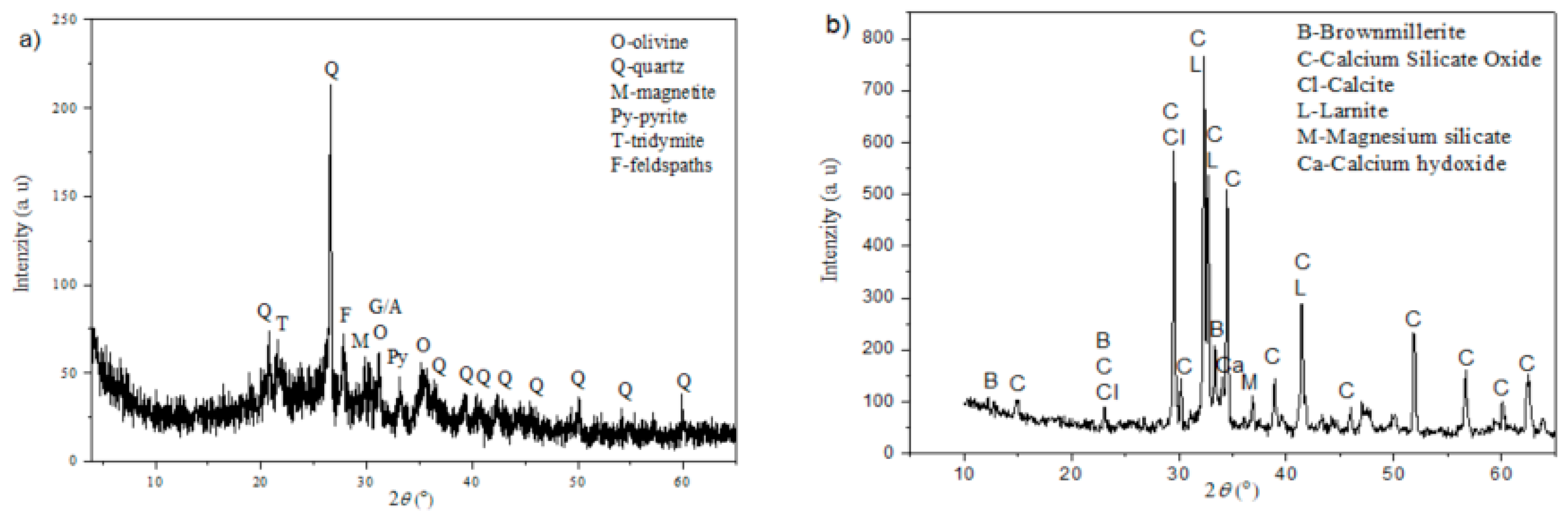
3.4. X-ray Structural Analysis (XRD)

For the determination of the crystal phase composition of the slag, XRD analysis was used and the results are shown in Figure 1. Additionally, XRD analysis of the CEM I 42.5R was performed and results are also shown in Figure 1.
It was determined that the slag sample possesses low crystallinity. However, crystal phases were detected, and the following minerals/phases were present: quartz, olivine, magnetite, pyrite, tridymite, feldspars. The most abundant mineral is quartz, while olivines and feldspars and then all other minerals/phases are less present. Of the feldspars, plagioclases are dominant, relative to K-feldspars.
The results of the XRD analysis of the CEM I 42.5R sample show its high crystallinity and the following minerals were detected: brownmillerite, calcium silicate oxide, calcite, larnite, magnesium silicate, calcium hydroxide. The most abundant phase is calcium silicate oxide, then brownmillerite, larnite and calcite, while magnesium silicate and calcium hydroxide are present as associate minerals. Of the larnite, larnite-beta (Ca2(SiO4) is dominant. The CEM I 42.5R crystallinity was high.

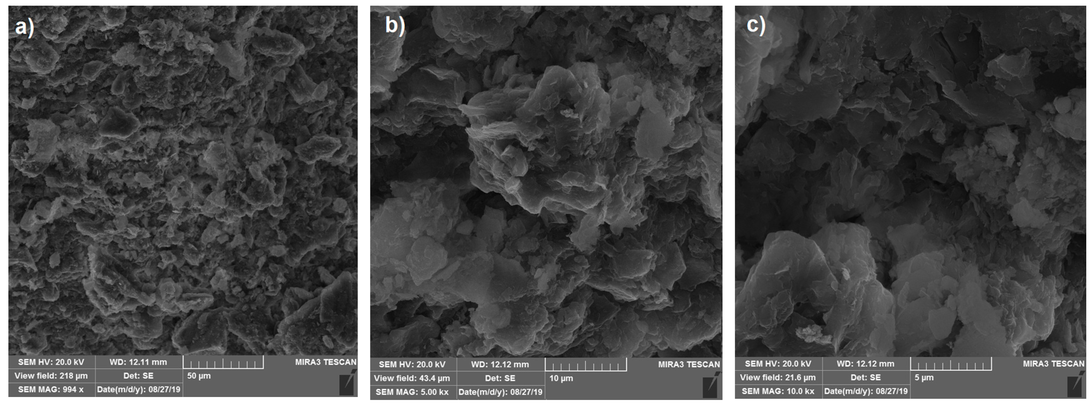
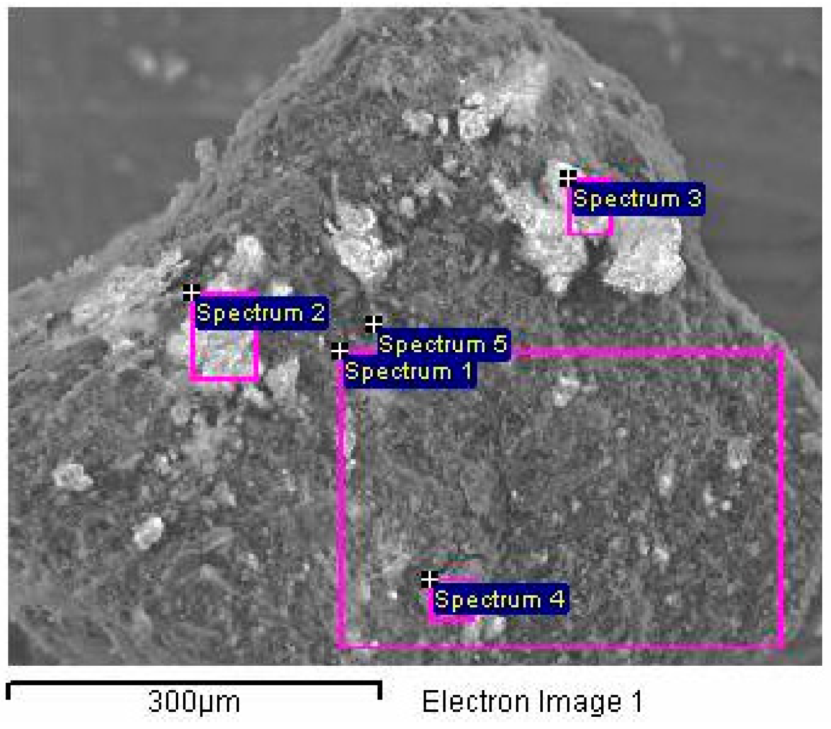
3.5. Scanning Electron Microscopy (SEM) Analysis

SEM images of the waste slag taken with different magnifications are shown at Figure 2.
From the micrographs taken with different magnifications, it can be seen that the slag is mainly constituted of aggregates of irregular size, which are mostly flat or have a granular structure. Micrographs taken with higher magnifications (5000× and 10000×) show that slag is mainly constituted of irregularly shaped aggregates of different sizes in the range of 2 to 10 µm. From the morphology of the investigated sample, it is also evident that the slag sample possesses cavities, which most likely originate from the loss of the bound aggregates on the surface during the combustion process of lignite or the drying of the sample, such as water molecules from the surface, organic molecules or carbonates.
The chemical composition of the surfaces of the slag is presented in Figure 3 and Table 7.
Five different positions and two measurement mods (spot and area) were used in order to get precise information about the chemical composition of the slag surface. Any chosen position for the EDS analysis of the surface composition of slag represents an aggregate of particles. This fact, pointed out previously in the analysis of the higher magnification micrographs, is confirmed by the analysis of the EDS spectrum results. The composition of the two spectra (one and five), of which spectrum one contains the results of the average composition of the surface at almost 0.1 mm2, and spectrum five contains the results of the composition at a point in the immediate vicinity of the edge of said surface, differ significantly. Indeed, the carbon content at position five is three times smaller, while the contents of Aluminum and Silicon are over two times higher in relation to the average composition of the chosen surface (spectrum one). Taking into account the processes, which simultaneously occurred during the burning of lignite (dehydration, partially or complete oxidation) and slag cooling and settling (possible carbonation and rehydration) as well as the different phases identified by the XRD analysis, complex highly heterogeneous surface composition is expected. Nevertheless, a reasonable degree of agreement is obtained by comparing the average values of the major analyte of the EDS analysis with the results obtained by classical chemical analysis (Section 3.1).

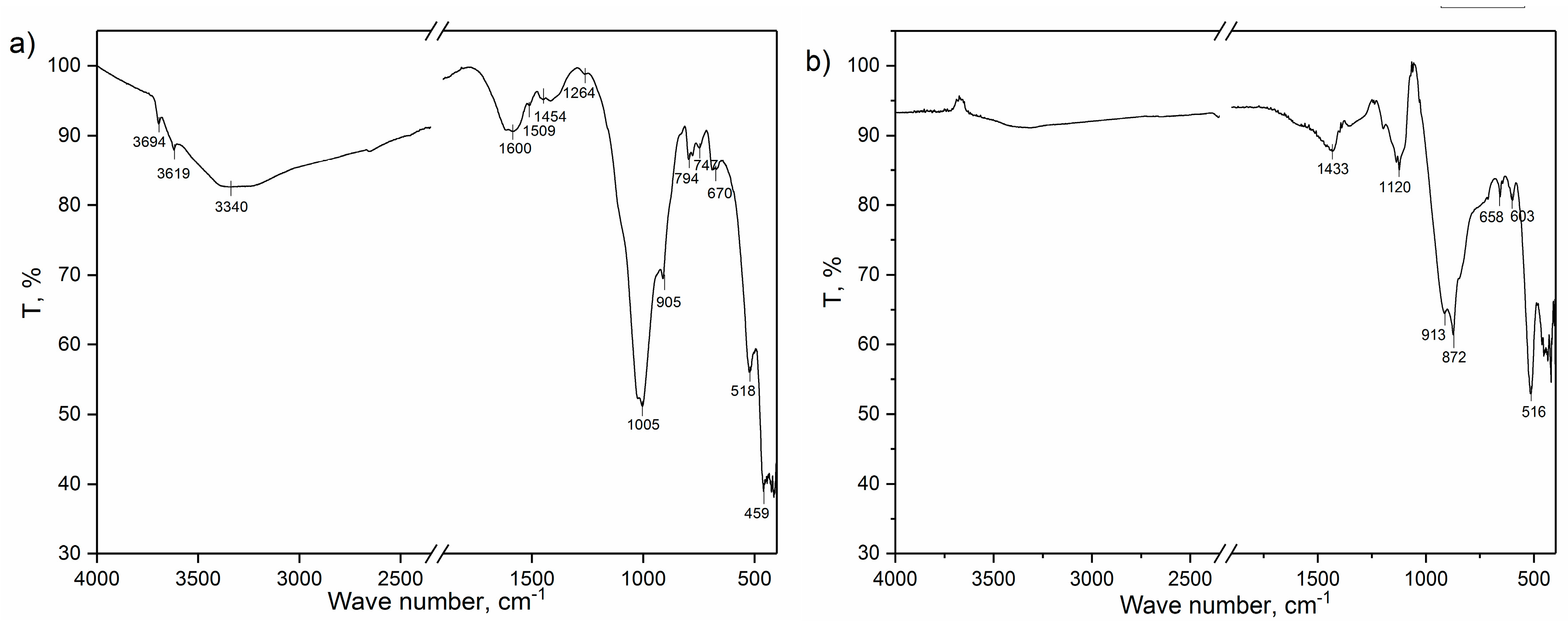
3.6. Infrared Spectroscopy with Fourier Transform (FTIR)

The infrared spectra of the starting slag sample and CEM I 42.5R are shown in Figure 4. In the infrared spectrum of the slag, spectral bands at 3697, 3619, 3340, 1618, 1585, 1509, 1454, 1264, 1025, 1005, 911, 796, 777, 692, 522 and 460 cm−1 are presented. The spectral bands at 3697 and 3619 cm−1 are assigned to the stretching vibrations of structural hydroxyl groups in Al-OH and Si-OH [40,41]. The spectral bands at 3340 and 1618 cm−1 may be assigned to the presence of the physical bounded and surface adsorbed water and stretching and banding vibrations of OH groups, respectively [40,41]. The position of the spectral band is related to the banding vibrations of OH and groups of water molecules may be an indication that water molecules interact through oxygen atoms with surface cations and act as an H-bond acceptor. Namely, according to the literature, a spectral band is usually obtained at 1630 cm−1 and shifting in its position may give information about the acidity/alkalinity of the surface. When a water molecule acts as an H-bond acceptor, the δ (H2O) is shifted to lower wave numbers; conversely, when it acts as H-bond donor, the δ (H2O) is shifted to higher wave numbers [42]. Spectral bands at 1025, 1005, 796, 777, 692, 520 and 460 cm−1 can be assigned to the Si-O vibrations. According to their positions and shape, they are clear confirmation of the presence of quartz, plagioclases and tridymite in the waste slag, which were also confirmed by XRD analysis [43,44,45]. Additional confirmation of the presence of the plagioclases (albite (NaAlSi3O8) and anorthite (CaAl2Si2O8)) is the spectral band at 911 cm−1, which originated from Al-Al-OH banding vibrations [40]. Bands originating from other minerals presented in the crystal phase of the slag sample were not visible due to them overlapping with much more pronounced bands in the spectrum. Spectral bands at 1585, 1509, 1454 and 1264 cm−1 originated from slag components that are in the amorphous phase and were not visible by XRD analysis. These spectral bands may be assigned to the organic components of the slag. Lignite, whose incomplete combustion produces slag, which is the subject of this research, is humus coal from deposits in Serbia, Kolubara basin and belongs to type III kerogen, which is formed from terrestrial plants, rich in cellulose and lignin, with low lipid content [46,47]. Such coals are mainly aromatic in nature, so the vibrations visible in the spectrum of the slag sample are mainly related to the vibrations in the aromatic rings. Thus, spectral bands at 1509 and 1454 cm−1 are assigned to the ν19a and ν19b in-plane, aromatic ring vibrations. Vibrations ν8a and ν8b (in-plane, aromatic ring stretch) are assigned in the FTIR spectrum with spectral bands at 1603 and 1585 cm−1. However, due to the overlapping of the band with lower intensity at 1603 cm−1 with those that originated from the vibration of the −OH group (at 1618 cm−1), only the line at 1585 cm−1 is visible in the spectrum. Stronger intensity of the band at 1585 cm−1 in comparison to the band at 1603 cm−1 indicates that the substituent on the ring is conjugated to the ring [48]. Finally, the spectral band at 1264 cm−1 may be assigned to enolic stretching C-O vibrations [49].
In the spectrum of the CEM I 42.5R, the band of 1433cm−1 is attributed to stretching vibrations of the CO3−2, and originates from the presence of calcium-carbonate (CaCO3) in cement [8,41] and also, this spectral band is characteristic for brownmillerite [50], which was also detected by the XRD analysis. The spectral band at 914 cm−1 originated from Al-Al-OH bending vibrations, and the band at 876 cm−1 may be assigned to Fe-Al-OH deformations, which also confirmed the presence of brown millerite (Ca2 (AlFe)2O5) while the band at 516 cm−1 originated from Al-O-Si bending vibrations. The band at 657 cm −1 is due to coupled Al-O and Si-O out of plane vibrations [8,39], while the band at 602 cm−1 is due to vibrations of internal modes of FeO6 in brown millerite. The bands at 420 and 465 cm−1 originated from O-Mg-O and O-Ca-O bending modes in minerals, which contain calcium (brown millerite, larnite, calcium silicate oxide and calcite) and magnesium silicate, respectively [51]. Spectral bands in the range 1200–1000 cm−1 are due to stretching (in plane and out of plane) vibrations of Si-O groups [8,40,41].

3.7. Testing of the Slag’s Pozzolanic Activity

The pozzolanic activity is one of the most important and basic parameters in order to determine if the investigated material can be used as a replacement for cement. For this reason, the AI of the slag was determined, and these investigations were performed in accordance with the EN 450-1 standard and the results are shown in Table 8.
Based on the results presented in Table 8, according to the parameters IST and S, the waste slag satisfied criteria, while according to parameters AI and WR, the waste slag does not satisfy parameters prescribed by the EN 450-1 standard, and thus, it may be concluded that the investigated slag does not possess pozzolanic activity in the presented form, and therefore it cannot be used as a replacement for cement without additional modifications and actions. In this study, this problem was solved with the addition of silica fume to the slag.
Namely, it is well known that silicate fume possesses good pozzolanic properties and because of this, it was tested as an addition to the slag in order to increase slag’s pozzolanic activity and improve its properties. At first, determination of the chemical composition of the silica fume was performed and the results shown in Table 9 confirm its very good quality (≈94% of SiO2).
After the determination of the chemical composition, the silica fume was used as an addition to slag during the production of cement mixtures. For this aim, five samples of the cement mixtures were prepared with different amounts of CEM I 42.5 R (the content was in range 100–75%), slag (the content was in range 8.9–22.2%) and silica fume (the content was in range 1.1–2.8%) as described in Table 10.
After the mixtures were prepared, the AI, as the most important parameter of all prepared mixtures, were determined, and the results are presented in Table 11.
From the presented results, it may be seen that slag with the addition of the silica fume possesses pozzolanic activity, which satisfies requirements prescribed by the EN 450-1 standard. Based on the measuring of the AI, the maximal possible cement replacement is 20% with 17.8% of slag and 2.2% of silica fume.

4. Conclusions

Results presented in this study show that waste slag—obtained from a heating plant (due to combustion of lignite) and taken from the landfill in Valjevo, Serbia—should be categorized as a hazardous waste due to its chemical composition and heavy metals content. From this point, it represents a serious environmental problem that must be solved.
Regarding slag utilization in the cement industry, results have shown that tested waste slag in the original form does not completely satisfy necessary criteria prescribed by the rulebooks from the aspect of the content of SiO2, Al2O3 and Fe2O3 as well as from the aspect of the content of the unburned carbon and loss of ignition. The proposed solution and the easiest way for solving and overcoming these problems is thermal treatment of the slag prior to use. The results of the thermal analysis show that, after thermal treatment up to 650 °C, all criteria related to heavy metals content and chemical composition can be met. Additional physical–chemical characterizations (XRD, FTIR, N2 physisorption, SEM, determination of the density) of the slag showed good correlation and that, regarding all additional tested physical–chemical properties, the slag completely satisfied the criteria prescribed by the rulebooks for utilization in cement industry.
Based on results of testing the physical–mechanical properties of the slag, it may be concluded that the investigated slag does not possess pozzolanic activity in its raw form, but with additional modifications and actions, it can be used as a replacement for cement. This may be overcome by mixing the slag with silica fume. The results show that mixing the slag with silica fume in minimal amounts (the slag/silica fume ration ≈0.88%/≈0.12%) improve the properties of the slag so that it possesses satisfactory pozzolanic activity. Maximal possible cement replacement was 20% with 17.8% of slag and 2.2% of silica fume. The results of leaching tests also prove that it is possible to use slag as mineral binders in cement composites, as there was no significant release of heavy metals.

Supplementary Materials

The following are available online at https://www.mdpi.com/2075-163X/10/11/992/s1, Figure S1: Results of thermal analyses of the: (a) slag and (b) CEM I 42.5R. Figure S2: Nitrogen isotherm of slag sample (insert-part of BET isotherm for SBET calculation).

Author Contributions

M.K. conceived and designed the experiments, wrote the paper, and contributed to all experiments and the analyzing of the obtained results. A.N. contributed to all experiments and the analyzing of the obtained results. M.S. and J.G. participated in SEM and thermal analyses and analyzed the results. S.M. performed XRPD analyses and explained obtained results. J.K. performed the determination of textural properties and contributed to the analysis of obtained results. N.R. performed physical–mechanical measurements and contributed to analyzing the results. All authors have read and agreed to the published version of the manuscript.

Funding

This research received funding from the Ministry of Education and Science of Serbia.

Acknowledgments

This work has been supported by the Ministry of Education and Science of Serbia.

Conflicts of Interest

The authors declare no conflict of interest.

References

  1. Mining Technology. Available online: https://www.mining-technology.com/features/feature-the-worlds-biggest-coal-reserves-by-country (accessed on 19 May 2020).
  2. Milovanović, Z. Chapter: 7 Edition: Monographs “Energy and process plants”. In Thermal Power Plants—Theoretical Bases; Faculty of Mechanical Engineering, University of Banja Luka: Banja Luka, Bosnia and Herzegovina, 2005; pp. 385–392. [Google Scholar]
  3. American Geosciences Institute. Available online: https://www.americangeosciences.org/critical-issues/faq/what-are-the-different-types-of-coal (accessed on 19 May 2020).
  4. Aydin, S.; Baradan, B. Effect of pumice and fly ash incorporation on high temperature resistance of cement based mortars. Cem. Concr. Res. 2007, 37, 988–995. [Google Scholar] [CrossRef]
  5. Statista. Available online: https://www.statista.com/statistics/605024/major-lignite-consuming-countries-globally/date (accessed on 8 April 2020).
  6. Dwivedi, A.; Jain, M. Fly ash—Waste management and overview: A Review. Recent Res. Sci. Technol. 2014, 6, 30–35. [Google Scholar]
  7. Terzić, A.; Mijatović, N.; Milićević, L.J.; Radojević, Z. Slag from coal combustion process as a secondary raw material for use in building composites. In Contemporary Materials and Constructions with Regulations, Belgrade, Serbia; Jevtić, D., Ed.; Society for Testing and Research of Materials and Structures: Belgrade, Serbia, 2016; pp. 51–60. [Google Scholar]
  8. Li, R.; Wang, L.; Yang, T.; Raninger, B. Investigation of MSWI fly ash melting characteristic by DSC–DTA. Waste Manag. 2007, 27, 1383–1392. [Google Scholar] [CrossRef] [PubMed]
  9. Wei, M.C.; Wey, M.Y.; Hwang, J.H.; Chen, J.C. Stability of heavy metals in bottom ash and fly ash under various incinerating conditions. J. Hazard. Mater. 1998, 57, 145–154. [Google Scholar] [CrossRef]
  10. Terzić, A.; Pezo, L.; Mijatović, N.; Stojanović, J.; Kragović, M.; Miličić, L.J.; Andrić, L.J. The effect of alternations in mineral additives (zeolite, bentonite, fly ash) on physico-chemical behavior of Portland cement based binders. Constr. Build. Mater. 2018, 180, 199–210. [Google Scholar] [CrossRef]
  11. Sun, X.; Yi, Y. pH evolution during water washing of incineration bottom ash and its effect on removal of heavy metals. Waste Manag. 2020, 104, 213–219. [Google Scholar] [CrossRef] [PubMed]
  12. European List of Waste, the Classification of Waste Based on: The European List of Waste (Commission Decision 2000/532/EC—Consolidated Version) and Annex III to Directive 2008/98/EC (Consolidated Version). Available online: http://data.europa.eu/eli/dec/2000/532/2015-06-01 (accessed on 25 September 2020).
  13. Official Journal of the Republic of Serbia No. 12/95. Available online: http://www.slglasnik.com/ (accessed on 1 February 2017).
  14. Decree of 20 December 2005—Official Journal of the Republic of Serbia No.113. Available online: http://www.slglasnik.com/ (accessed on 20 December 2005).
  15. Liu, X.; Ni, C.; Meng, K.; Zhang, L.; Liu, D.; Sun, L. Strengthening mechanism of lightweight cellular concrete filled with fly ash. Constr. Build. Mater. 2020, 251, 118954. [Google Scholar] [CrossRef]
  16. Wong, G.; Fan, X.; Gan, M.; Ji, Z.; Ye, H.; Zhou, Z.; Wang, Z. Resource utilization of municipal solid waste incineration fly ash in iron ore sintering process: A novel thermal treatment. J. Clean. Prod. 2020, in press. [Google Scholar] [CrossRef]
  17. Cai, J.; Pan, J.; Li, X.; Tan, J.; Li, J. Electrical resistivity of fly ash and metakaolin based geopolymers. Constr. Build. Mater. 2020, 23420, 117–868. [Google Scholar] [CrossRef]
  18. Hu, C. Microstructure and mechanical properties of fly ash blended cement pastes. Constr. Build. Mater. 2014, 73, 618–625. [Google Scholar] [CrossRef]
  19. Zabielska-Adamska, K. Laboratory compaction of fly ash and fly ash with cement additions. J. Hazard. Mater. 2008, 151, 481–489. [Google Scholar] [CrossRef]
  20. Nadesan, M.; Dinakar, P. Mix design and properties of fly ash waste lightweight aggregates in structural lightweight concrete. Case Stud. Constr. Mater. 2017, 7, 336–347. [Google Scholar] [CrossRef]
  21. Terzić, A.; Pavlović, L.J.; Radojević, Z.; Pavlović, V.; Mitić, V. Novel Utilization of Fly Ash for High-temperature Mortars: Phase Composititon, Microstructure and Performance Correlation. Int. J. Appl. Ceram. Technol. 2015, 12, 133–146. [Google Scholar] [CrossRef]
  22. Wang, S.; Baxter, L.; Fonseca, F. Biomass fly ash in concrete: SEM, EDX and ESEM analysis. Fuel 2008, 87, 372–379. [Google Scholar] [CrossRef]
  23. Adu-Amankwah, S.; Zajac, M.; Stabler, C.; Lothenbach, B. Influence of limestone on the hydration of ternary slag cements. Cem. Concr. Res. 2017, 100, 96–109. [Google Scholar] [CrossRef]
  24. Sun, H.; Quian, J.; Yang, Y.; Fan, C.; Yue, Y. Optimization of gypsum and slag contents in blended cement containing slag. Cem. Concr. Compos. 2020, 112, 103674. [Google Scholar] [CrossRef]
  25. Yoon, H.N.; Seo, J.; Kim, S.; Lee, H.K.; Park, S. Characterization of blast furnace slag-blended Portland cement for immobilization of Co. Cem. Concr. Res. 2020, 134, 106089. [Google Scholar] [CrossRef]
  26. Voinovitch, I.; Debrad-Guedon, J.; Louvrier, J. The Analysis of Silicates; Israel Programfor Scientific Translations: Jerusalem, Israel, 1966. [Google Scholar]
  27. Gregg, S.J.; Sing, K.S.W. Adsorption, Surface Area and Porosity, Berichte der Bunsengesellschaft für Physikalische Chemie; Hansen, N., Ed.; Academic Press: New York, NY, USA; London, UK, 1967; p. 71. [Google Scholar]
  28. Dubinin, M.M. Physical adsorption. In Progress in Surface Press, and Membrane Science; Cadenead, D.A., Danielli, J.F., Rosenberg, M.D., Eds.; Academic Press: New York, NY, USA; London, UK, 1975; Volume 9, pp. 1–70. [Google Scholar]
  29. Dollimore, D.; Heal, G.R. An improved distribution method for the calculation of pore size from adsorption data. J. Appl. Chem. 1964, 14, 109–114. [Google Scholar] [CrossRef]
  30. Hewlett, P.C. Lea’s Chemistry of Cement and Concrete, 4th ed.; Elsevier Ltd.: Oxford, UK, 1998. [Google Scholar]
  31. Marinković, S.; Trifunović, P.; Tokalić, R.; Matijašević, S.; Kostić-Pulek, A. DTA/TGA studies of bottom ash from the Nikola Tesla power plant from Serbia for the purpose of its utilization in road construction. In Proceedings of the 36th International Conference of SSCHE, Tatranské Matliare, Slovakia, 25–29 May 2009; pp. 094-1–094-8. [Google Scholar]
  32. Maroto-Valer, M.; Taulbee, D.; Hower, J. Characterization of differing forms of unburned carbon present in fly ash separated by density gradient centrifugation. Fuel 2001, 80, 759–800. [Google Scholar] [CrossRef]
  33. Hill, R.; Sarkar, S.; Rathbone, R.; Hower, J. An examination of fly ash carbon and itsinteractions with air entraining agent. Cem. Concr. Res. 1997, 27, 193–204. [Google Scholar] [CrossRef]
  34. Millán-Corrales, G.; González-López, J.R.; Palomo, A.; Fernandez-Jiménez, A. Replacing fly ash with limestone dust in hybrid cements. Constr. Build. Mater. 2020, 243, 118–169. [Google Scholar] [CrossRef]
  35. Soriano, I.; Tashima, M.; Bonilla, M.; Payá, J.; Monzó, J.; Borrachero, M. Use of high resolution thermo gravimetric analysis (HRTG) technique in spent FCC catalyst/Portland cement pastes. J. Therm. Anal. Calorim. 2015, 120, 1511–1517. [Google Scholar] [CrossRef]
  36. Scrivener, K.; Snellings, R.; Lothenbach, B. Chapter 5 (Thermogravimetric Analysis), A Practical Guide to Micostructural Analysis of Cementitious Materials, 1st ed.; Taylor and Francis Group: Oxford, UK, 2016; p. 36. [Google Scholar]
  37. Zeng, Q.; Li, K.; Chong, T.; Dangla, P. Determination of cement hydration and pozzolanic reaction extents for fly-ash cement pastes. Constr. Build. Mater. 2012, 27, 560–569. [Google Scholar] [CrossRef]
  38. Bertier, P.; Schweinar, K.; Stanjek, H.; Ghanizadeh, A.; Clarkson, C.R.; Busch, A.; Kampman, N.; Prinz, D.; Amann-Hildenbrabd, A.; Krooss, B.M.; et al. On the use and abuse of N2 physisorption for the characterization of the pore structure of shales. Clay Miner. Soc. Workshop Lect. 2016, 21, 151–161. [Google Scholar]
  39. Thommes, M.; Kaneko, K.; Neimark, V.A.; James, P.O.; Rodriguez-Reinoso, F.; Rouquerol, J.; Sing, W.K.S. Physisorption of gases, with special reference to the evaluation of surface area and pore size distribution (IUPAC Technical Report). Pure Appl. Chem. 2015, 87, 1051–1069. [Google Scholar] [CrossRef] [Green Version]
  40. Patel, H.A.; Somani, S.R.; Bajaj, C.H.; Jasra, V.R. Nanoclays for polymer nanocomposites, paints, inks, greases and cosmetics formulations, drug delivery vehicle and waste water treatment. Bull. Mater. Sci. 2006, 29, 133–145. [Google Scholar] [CrossRef]
  41. Wu, H.; Xie, H.; He, G.; Guan, Y.; Zhang, Y. Effects of the pH and anions on the adsorption of tetracycline on iron-montmorillonite. Appl. Clay Sci. 2016, 119, 161–169. [Google Scholar] [CrossRef]
  42. Fesenko, O.; Yatsenko, L.; Brodin, M. Nano materials Imaging Techniques, Surface Studies, and Applications; Springer: Berlin, Germany, 2012; p. 146. [Google Scholar]
  43. Database of ATR-FT-IR Spectra of Various Materials. Available online: http://lisa.chem.ut.ee/IR_spectra/paint/fillers/quartz/ (accessed on 23 May 2020).
  44. Correcher, V.; Garcia-Guinea, J.; Bustillo, A.M.; Garcia, R. Study of the thermoluminescence emission of a natural α-cristobalite. Radiat. Eff. Defects Solids 2009, 164, 59–67. [Google Scholar] [CrossRef]
  45. Bosch-Reig, F.; Gimeno-Adelantado, J.V.; Bosch-Mossi, F.; Doménech-Carbó, A. Quantification of minerals from ATR-FTIR spectra with spectral interferences using the MRC method. Spectrochim. Acta Part A Mol. Biomol. Spectrosc. 2017, 181, 7–12. [Google Scholar] [CrossRef]
  46. Obradović, M. Research and Comparison of the Influence of Low Rank Coals Characteristics on Their Grindability and Milling Process Parameters. Ph.D. Thesis, Faculty of Mechanical Engineering, University of Belgrade, Belgrade, Serbia, 2015. [Google Scholar]
  47. Mitrović, D. Origin and Paleoenvironmental Reconstruction of the “Kovin” Coal Deposit—Implications from Petrographic and Geochemical Investigations. Ph.D. Thesis, Faculty of Chemistry, University of Belgrade, Belgrade, Serbia, 2018. [Google Scholar]
  48. Mayo, D.V.; Miller, F.A.; Hannah, R.W. Course Notes on the Interpretation of Infrared and Raman Spectra; John Wiley and Sons: Hoboken, NJ, USA, 2003. [Google Scholar]
  49. Mane, V.G. Studies of Some Transition Metal Complexes of Schiffõs Bases. Lulu.Com. 2019. Available online: https://books.google.rs/books?hl=en&lr=&id=RVePDwAAQBAJ&oi=fnd&pg=PA19&ots=_Z8TVoH9Ph&sig=U2YqsX98CeXlMr4exwqcajZTtok&redir_esc=y#v=onepage&q&f=false (accessed on 25 September 2020).
  50. Singh, S.; Menon, S.; Gupta, K.; Jayavel, R. Preferentially oriented single crystal growth of brownmillerite CaFeO2.5 by flux growth technique. Mater. Lett. 2014, 131, 332–335. [Google Scholar] [CrossRef]
  51. Choudhary, R.; Koppala, S.; Swamiappan, S. Bioactivity studies of calcium magnesium silicate prepared from eggshell wastebysol–gelcombustionsynthesis. J. Asian Ceram. Soc. 2015, 3, 173–177. [Google Scholar] [CrossRef] [Green Version]
Figure 1. Results of the XRD analyses of the (a) slag and (b) CEM I 42.5R.
Minerals 10 00992 g001
Figure 2. SEM micrographs of slag measured with different magnifications: (a) 994×, (b) 5000× and (c) 10000×.
Minerals 10 00992 g002
Figure 3. EDS-SEM micrography of waste slag.
Minerals 10 00992 g003
Figure 4. Infrared spectra of the: (a) slag and (b) CEM I 42.5R.
Minerals 10 00992 g004
Table 1. Compositions (in weight percentages, wt.%) of the slag and CEM I 42.5R and values prescribed by the standard.
ParameterSiO2Fe2O3Al2O3CaOMgOSO3Na2OK2OP2O5TiO2LOI *
Slag21.2010.8115.706.322.501.782.670.630.0360.6237.45
CEM I 42.5R21.622.607.0060.162.342.550.330.66-2.68
Standard70 < SiO2 + Fe2O3 + Al2O3≤10.0≤4.0≤3.0≤5.0-≤5.0≤11.0
* LOI—loss of ignition. Annealing temperature 1050 °C; ignition time 2 h.
Table 2. Compositions of the slag after additional thermal treatment (in weight percentages, wt.%).
ParameterSiO2Fe2O3Al2O3CaOMgOSO3Na2OK2OTiO2P2O5
Slag33.7517.4625.9610.003.982.844.251.000.700.0573
Table 3. The content of heavy metals in slag. Concentration is expressed as mg/kg.
SampleCrCuLiMnNiPbZnCdSnSbAg
Slag1385131600110480362.2<51605.4
Limit value *7040505.0
* Lower limit value for the classification of waste as hazardous waste, according to the rulebook on the categories, testing and classification of waste, Official Journal of the Republic of Serbia No 56/2010.
Table 4. Concentration of the released elements after the leaching test. Concentration is expressed in µg/dm3.
Released ElementConcentrationAllowed Values *
Cr754000–12,000
Cu816000–12,000
Mn114-
Ni1543000–7500
Pb5635000–15,000
Zn6686000–20,000
Cd2950–200
Ag21-
* According to the rulebook on permitted quantities of hazardous and harmful materials in agricultural land and water for irrigation and methods for testing—applicable in Serbia.
Table 5. Weight loss in different temperature intervals for slag and CEM I42.5R samples.
Weight Loss, %
Temperature25–150 °C200–650 °C650–800 °C800–1000 °C25–1000 °C
Slag4.0032.780.610.00138.31
Temperature25–400 °C400–1000 °C25–1000 °C
CEM I 42.5.0.656.877.52
Table 6. Properties of the slag sample.
SampleSBET, m2/gVmeso, cm3/gVmic, cm3/g
Slag25.00.0200.010
Table 7. Composition of the slag surfaces at selected positions expressed in weight percentages (wt.%).
Spectrum NumberElement Concentration
COAlSiFeTiCaMgKNaS
138.5733.156.111.345.030.313.430.700.70-0.67
227.9642.247.8314.862.980.321.850.690.640.130.52
341.9235.255.438.13.080.253.440.90.5-1.14
434.1336.257.1213.024,001.752.070.650.68-0.33
512.6235.5213.2224.996.40.323.381.161.59-0.8
Table 8. Test results of physical and mechanical characteristics of slag.
Properties100% CEM75% CEM + 25% SlagRequirements EN 450-1
Activity index, %-28 days–76.9
90 days–76.4
28 days–75 *
90 days–85 *
Water Requirement, %-113<95% of CEM *
Setting time, mininitial 115
final 165
initial 170
final 215
<2 × 100% CEM **
-
Soundness, mm1.01.5<10.0 **
* According to the EN 450-1 standard; ** according to EN 196-3.
Table 9. Chemical composition of silica fume expressed in weight percentages (wt.%).
ParameterSiO2Fe2O3Al2O3CaOMgOSO3Na2OK2OP2O5LOI
Silica fume93.600.210.270.050.050.800.230.50-2.40
Table 10. Preparation of the mixtures with the additions of the different amounts of the silicate fume.
MarkEP10-3P15-3P20-3P25-3
DescriptionEtalon
(without CEM replacement)
CEM replacement with 8.9% of slag and 1.1% silica fume.
Total replacement of CEM = 10%
CEM replacement with 13.3% of slag and 1.7% silica fume.
Total replacement of CEM = 15%
CEM replacement with 17.8% of slag and 2.2% silica fume.
Total replacement of CEM = 20%
CEM replacement with 22.2% of slag and 2.8% silica fume.
Total replacement of CEM = 25%
Table 11. Activity indexes of mixtures with different amounts of silica fume.
Mix CodeActivity Index/%Requirements EN 450-1/%
P1028 days–95.1
90 days–93.2
28 days–75
90 days–85
P1528 days–90.8
90 days–89.1
P2028 days–86.9
90 days–85.2
P2528 days–82.3
90 days–81.1
Publisher’s Note: MDPI stays neutral with regard to jurisdictional claims in published maps and institutional affiliations.

