Crystallographic and Seismic Anisotropies of Calcite at Different Depths: A Study Using Quantitative Texture Analysis by Neutron Diffraction
Abstract
1. Introduction
2. Samples Description and Geological Setting
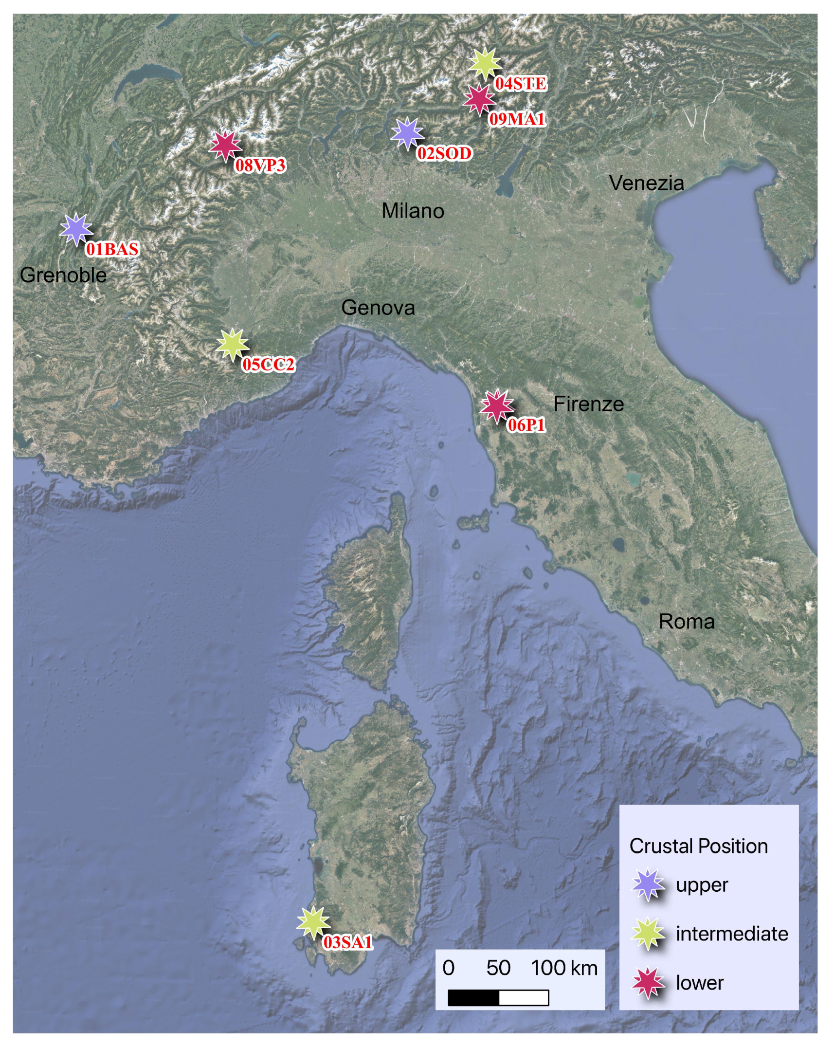
- The BAS sample is a light gray crystalline limestone, fine-grained, homogeneous, and free of any planar fabrics at the macroscopic scale, both primary or secondary, as fractures or joints. It is Jurassic in age and it belongs to the External thrust-belt French Subalpine system [25,26]; it is part of the so-called Calcaires “tithoniques” [27]. It was sampled close to Grenoble (France), La Bastille, the southernmost part of the Chartreuse massive. According to the tectonic reconstruction and the local geologic map [27,28], the thrust system developed a km-scale anticline, associated with brittle faults and fracture systems. The BAS sample has been collected within this anticline but far from the brittle system. The fold and thrust system occurred at <3 km depth, at temperature <100 C.
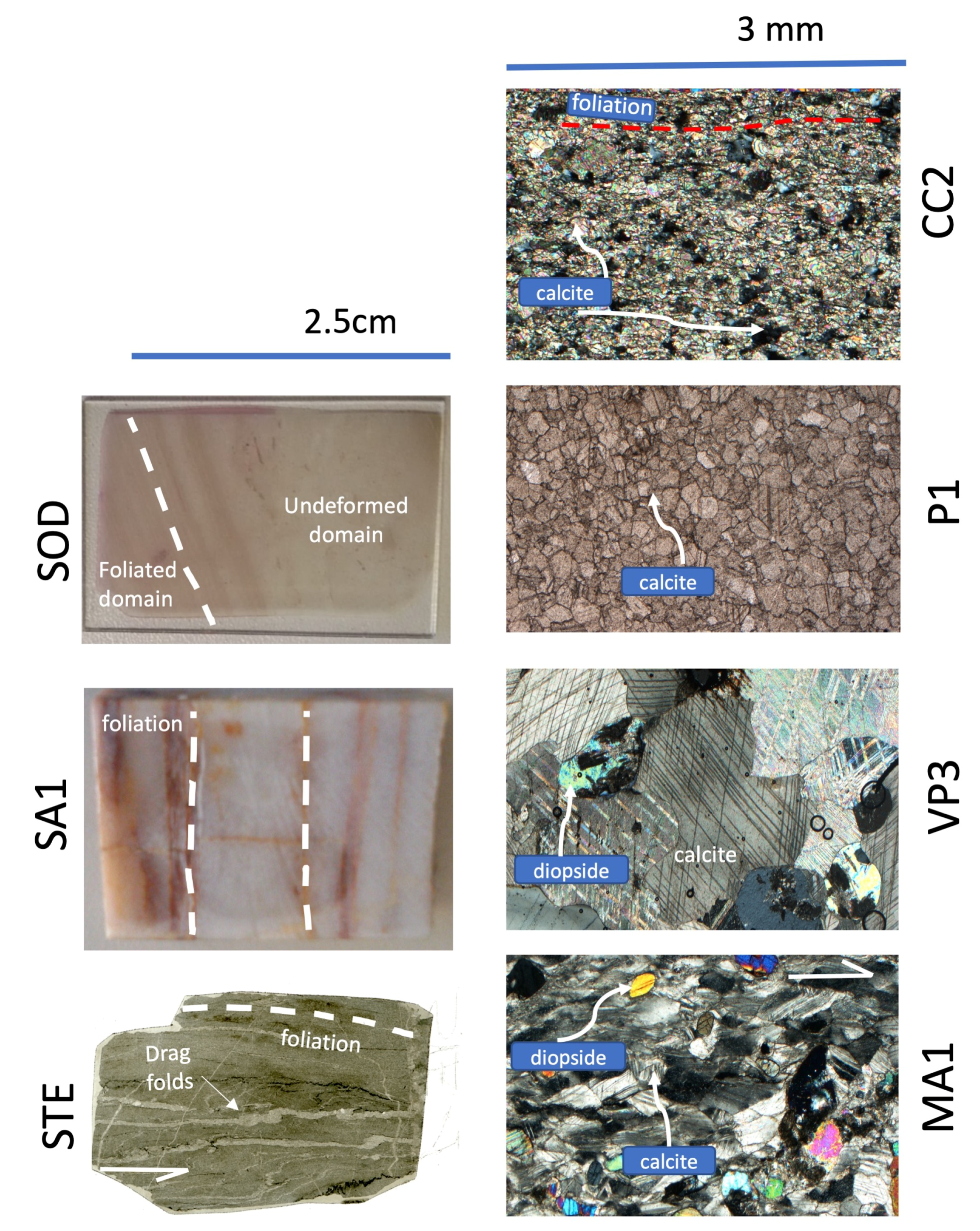
- The SOD sample was collected in the Southalpine domain. The sample is part of the Triassic cover, which crops along the entire Southalpine domain. The general interpretation infers the thrust and fold system to convergent tectonics active during the formation of the Alpine system (Figure 1 and Figure 2). It was collected within the meter-scale mylonitic horizons associated with a meter to tens of meters asymmetric folds [29]. According to these authors, the thrust horizons occurred at relatively upper depth, not exceeding 5–7 km, corresponding to a maximum of 200 C. The studied sample shows an abrupt change in fabric from undeformed to highly strained domains (Figure 2), often associated with grain-size reduction, pressure-solution, and plastic deformation in carbonate grains, testified by mechanical twinning. These meso- and microstructures support temperatures as high as 200 C [30,31]. The kinematics of these thrust horizons have been reconstructed based on stratigraphic and structural constraints, being characterized by strong simple shear components also testified by classical shear indicators, as cm- to mm-scale drag folds and porphyroclasts geometries [32].
- SA1 sample was collected in the Sardinia basement. It is part of the Ceroidi Limestone (Gonnesa Fm.), pre-Ordovician protolith of the External Zone. This metasedimentary cover has been deeply involved in the Paleozoic-Variscan tectonics [33]. During the Variscan tectonic activity, green-schists metamorphic conditions were attained [34], locally associated with high strain shear horizons, from meters to tens of meters thick [35,36]. The SA1 sample was collected in one of these high strain horizons, made by meta-carbonate limestone. The Variscan deformation developed as pervasive folding systems. However, the SA1 sample was collected far from folds and within the domain where the mylonitic foliation is well visible at the macroscopic scale (Figure 2). As qualitative estimates for pressure and temperature, the intermediate limit can be put following the metamorphic evolution of the inner part of the belt, as described by Elter et al. [37]. Consequently, a limit of 350 C and 4–5 kbar, corresponding to roughly 12–15 km depth can be used to constrain the development of the fabric on this horizon. Moreover, mesoscopically no asymmetric shear sense indicators have been recognized, supporting the microstructural and textural observations [35], which suggested a pure shear strain.
- STE sample was collected in the Central Alps, within the intermediate Austroalpine domain [38]. Here the Mesozoic sedimentary cover was involved in the Alpine tectonics, occurring as thick-skinned thrusting of cover and its pre-alpine basement [39]. Thrusting localized along high strain horizons within cover and basement [40]. The temperature conditions of this event were estimated at T = 300–350 C at depth = 15–20 km [41,42]. We collected a sample within the mylonite horizons in the Mesozoic cover, namely the Fraele Fm. It is characterized by a strongly developed mylonite fabric, associated with a meter- to tens of meter folds. A strong transposition of the lithostratigraphic features has been recorded along this horizon [43]. A simple shear component has been described for this deformation based on meso- and microstructural analysis [41]. Sample scale features, as mm-sized drag faults (Figure 2), support the simple shear component.
- CC sample was collected in the Western Alps, in the sub-Briançonnais domain. It consists of Jurassic limestone strongly deformed during Alpine thrusting of the external part of the chain [44]. According to [45,46] the External Briançonnais units equilibrated at a pressure not exceeding 5 kbar, corresponding to depths <15 km, and T = 300–350 C. Moreover, overall simple shear kinematics is constrained by map- to micro-scale indicators, extensively described in the area [47,48,49]; however, the studied sample does not show clear microstructures that could be uniquely related to a simple shear geometry (Figure 2).
- P1 was collected in the well-known Carrara marbles quarries. They consist of the Mesozoic cover of the Autochthon of the Tuscan Units metamorphosed during the Alpine evolution [50,51]. Km- to meter-scale folding systems have been mapped, and several kinematics reconstructions have been proposed [52] suggesting large scale shear, related to the thrusting of the deep units, resulted in meso- and micro-scale simple shear fabrics (e.g., [20,53]). However, large scale strain partitioning also occurred, allowing a large volume of marbles to escape the development of planar or linear fabrics [54]. In fact, the studied sample is characterized by isotropic equigranular texture of recrystallized calcite (Figure 2), suggesting a static recrystallization process associated with grain-boundary migration both leading to grain size increase [32]. Within the Alpi Apuane Metamorphic Complex the estimated conditions of metamorphism point to T = 400–500 C at 8–10 kbar [50,55,56], corresponding to 25–30 km depth.
- VP3 and MA1 were both collected in the Austroalpine domain of the Alps [44]. The Austroalpine domain is interpreted as fragments of the pre-alpine continental crust involved in the Alpine subduction-collision system. The collected samples are marbles whose metamorphism has produced during high-temperature Permian–Triassic extension [57]. VP3 was collected in the Valpelline Series, Austroalpine of the Western Alps [58,59], while MA1 was collected in the Languard-Campo, Austroalpine domain of the Central Alps [60]. They are characterized by 0.5–1.5 mm (VP3) to <0.5 mm (MA1) grain-size and strong planar fabric, marked by the shape preferred orientation of calcite and local diopside and quartz (Figure 2). They display diffuse mechanical twinning and undulose extinction, both suggesting grain-scale plastic deformation [32]. Shear indicators are not univocal, MA1 often shows asymmetrical bending of calcite tails around porphyroblast suggesting a component of simple shear, but pure shear cannot be ruled out. Similarly, VP3 displays a less tendency to develop asymmetric microstructures, point to a greater contribution of pure shear. Metamorphic conditions have been quantitatively determined for both samples, VP3 developed at T = 700–800 C and P > 6 kbar, corresponding to >18 km depth, while MA1 fabric was estimated to form at T = 600–750 C and P = 6.5–7.5 kbar, corresponding to 20–24 km depth [58,60].
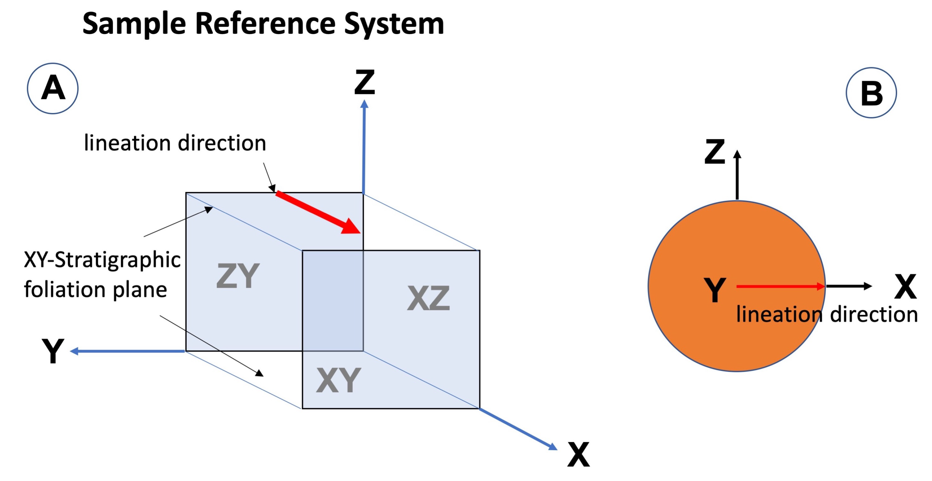
3. Sample Reference System and Methods
4. Results
4.1. Textures
4.2. Seismic Velocities
5. Discussion
5.1. Texture Types Evolution with Temperature, Pressure, Shear Geometry, and Strain
5.2. Seismic Anisotropy
6. Conclusions
- Eight samples of limestones and marbles were studied by neutron diffraction. We collected Texture of naturally deformed calcite at different depths in the crust, from upper to lower crust.
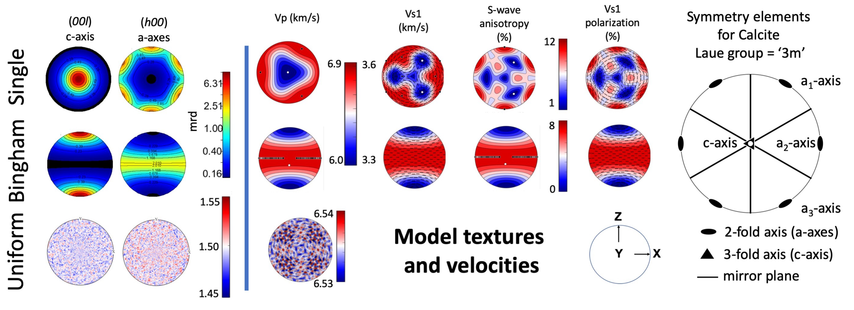
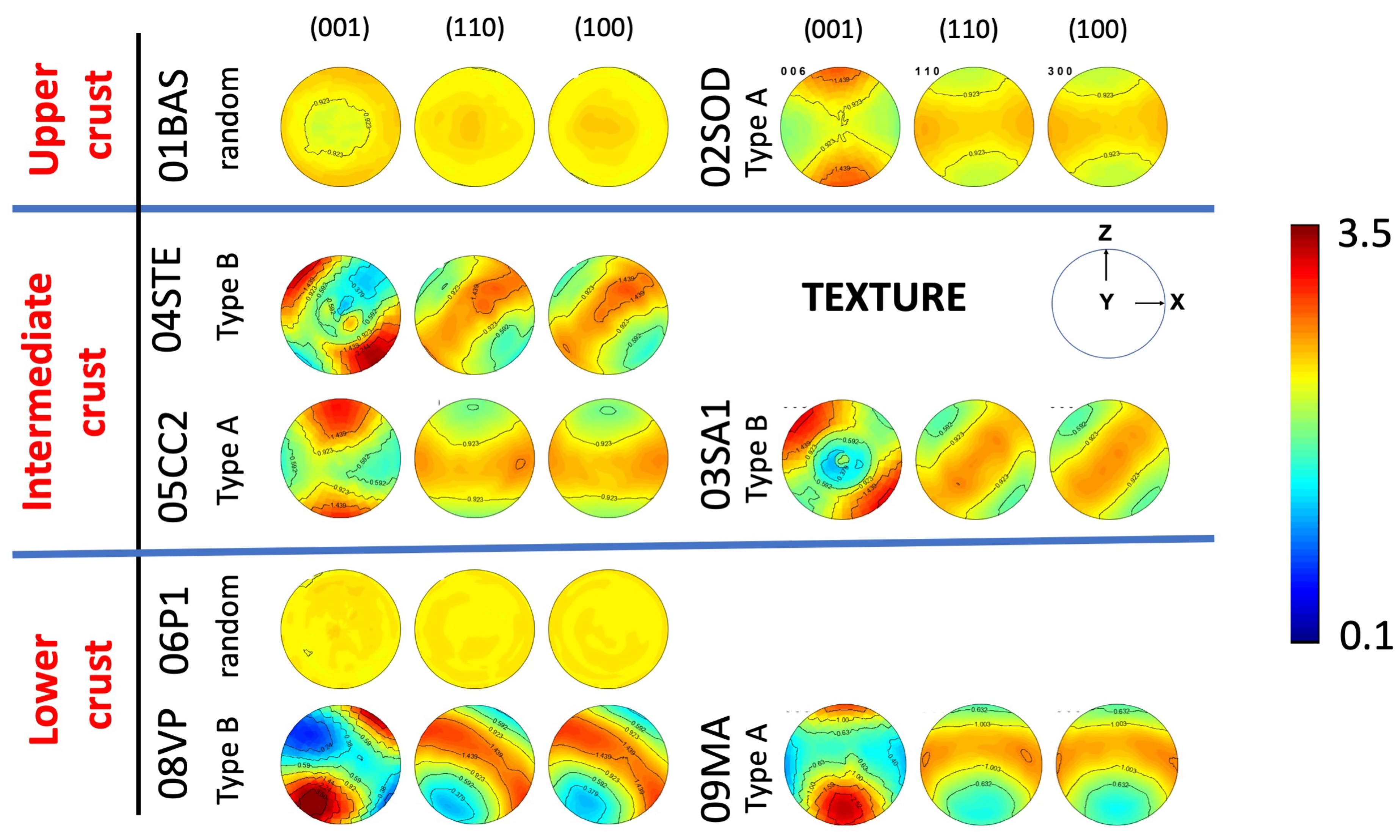
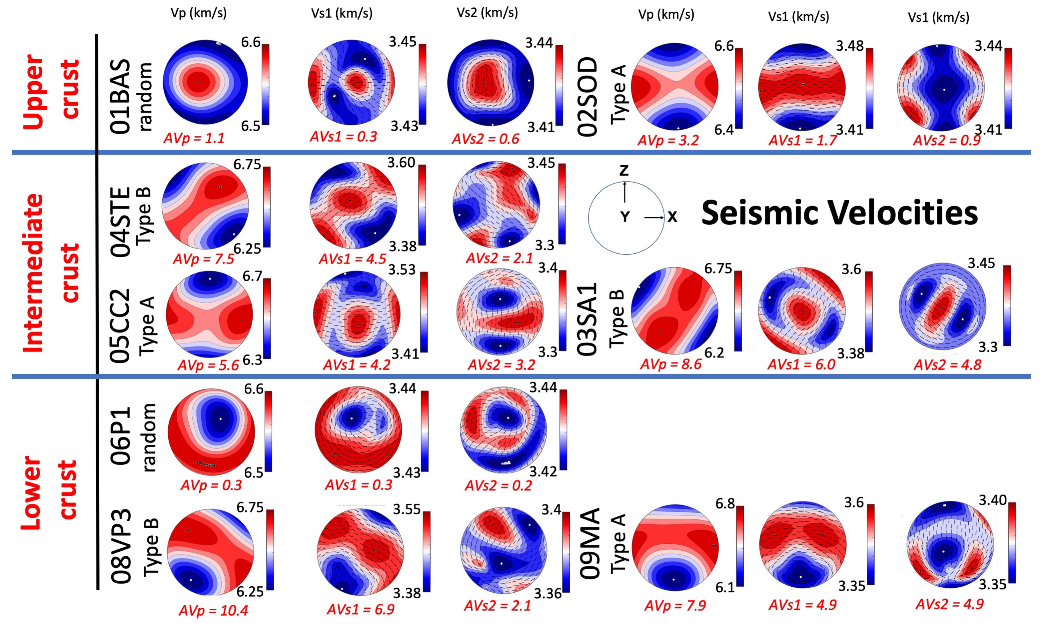
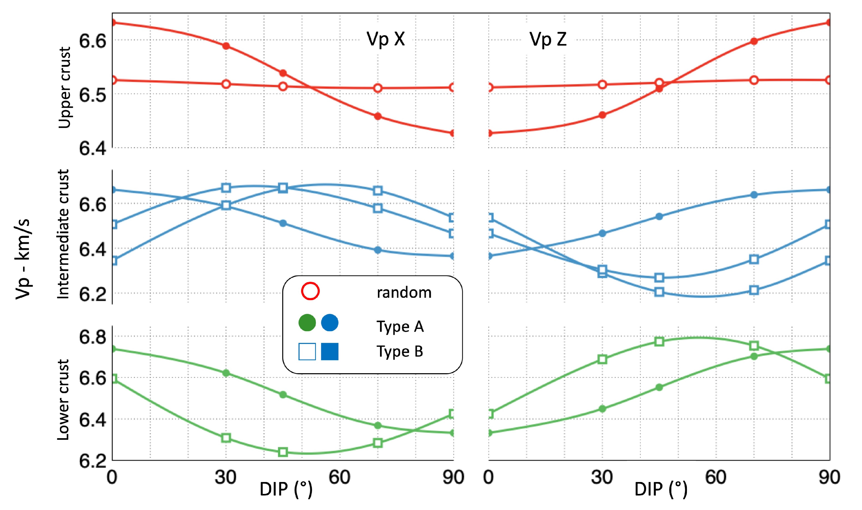
- Different Texture patterns were recognized, from random to strongly textured (Type B); the latter, with orthorhombic (Type A) or monoclinic (Type B) symmetries. Seismic anisotropies were calculated using the Orientation Distribution Function to homogenize the elastic tensor of calcite.
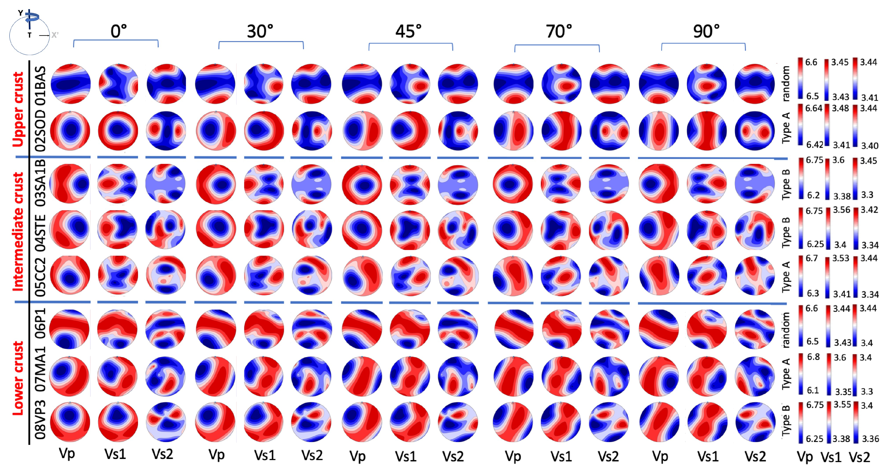
- A wide variability of seismic anisotropies arise from the various textural types, crustal positions, and dipping of the shear planes.
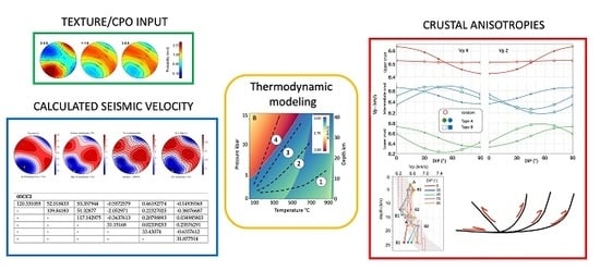
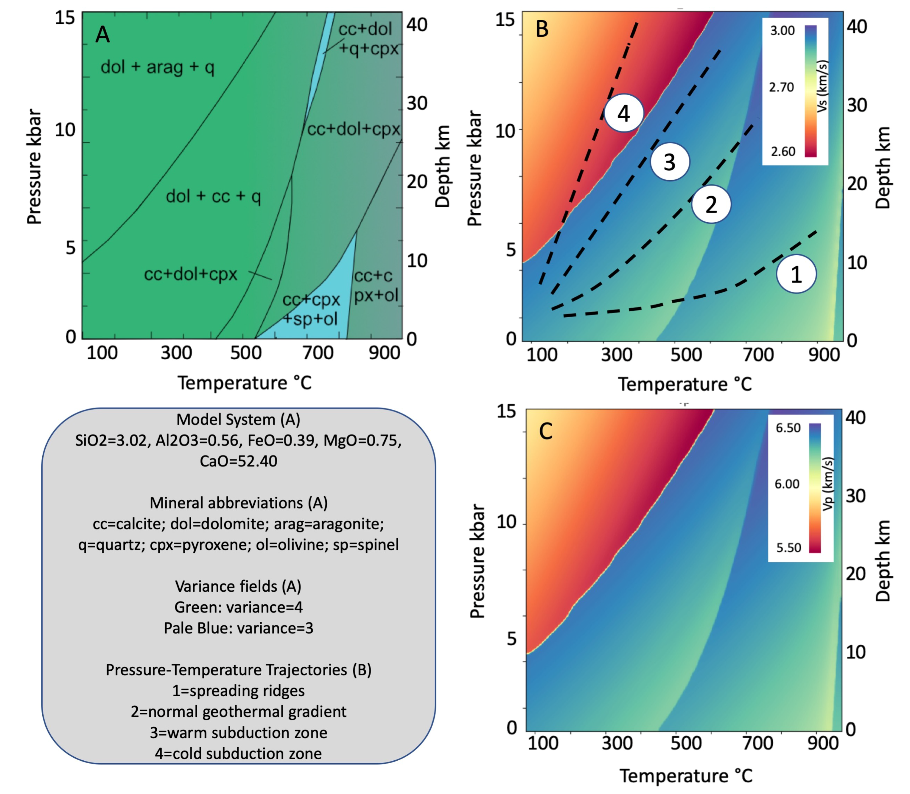
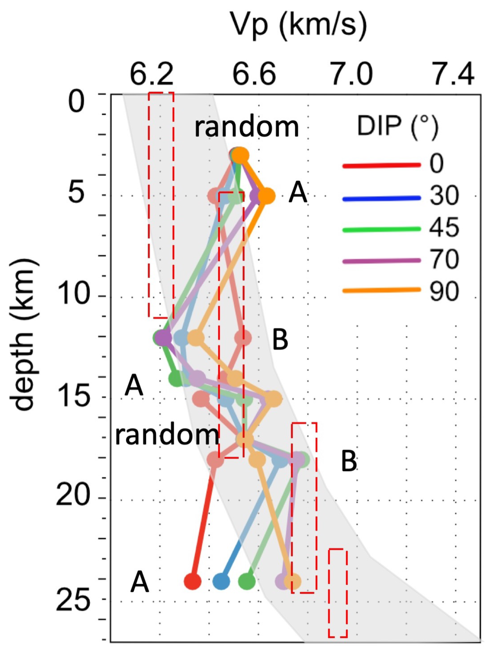
- These results may be valuably used to guess geometry of shear zones at upper to depth for carbonate rocks or at deeper crustal levels where thick carbonatic horizons are involved localizing deformation (Figure 11).
- This work suggests that at depth, even for carbonate rocks, there is an important overlapping between different rock types in term of their seismic properties (Figure 11); unambiguous determination of geological information from natural seismic must consider the orientation of the macroscopic fabric, shear foliation, lineation, or any fabric associated with texture playing a role in developing seismic anisotropies [24,84].
- Lastly, texture types may produce unique seismic velocities pattern. For example, Type A (Figure 11) produces a unique pattern at any depth, characterized by an increase of Vp velocities (e.g., 6.3 to 6.8 at 20–25 km depth) as the dipping angle increases. Future studies may show if these singular patterns might be used to better constrain the interpretation of seismic profiles.
Supplementary Materials
Author Contributions
Funding
Acknowledgments
Conflicts of Interest
References
- Lowrie, W. Fundamentals of Geophysics; Cambridge University Press: New York, NY, USA, 2007; 390p. [Google Scholar] [CrossRef]
- Sun, L.; Fang, C.; Sa, L.; Yang, P.; Sun, Z. Innovation and prospect of geophysical technology in the exploration of deep oil and gas. Shiyou Kantan Yu Kaifa/Pet. Explor. Dev. 2015, 42, 414–424. [Google Scholar] [CrossRef]
- Kendall, J.-M.; Fisher, Q.J.; Covey Crump, S.; Maddock, J.; Carter, A.; Hall, S.A.; Wookey, J.; Valcke, S.L.A.; Casey, M.; Lloyd, G.; et al. Seismic anisotropy as an indicator of reservoir quality in siliciclastic rocks. Geolog. Soc. Lond. Spec. Publ. 2007, 292, 123–136. [Google Scholar] [CrossRef]
- Okaya, D.; Vel, S.S.; Song, W.J.; Johnson, S.E. Modification of crustal seismic anisotropy by geological structures (“structural geometric anisotropy”). Geosphere 2019, 15, 146–170. [Google Scholar] [CrossRef]
- Faccenda, M.; Ferreira, A.M.; Tisato, N.; Lithgow-Bertelloni, C.; Stixrude, L.; Pennacchioni, G. Extrinsic Elastic Anisotropy in a Compositionally Heterogeneous Earth’s Mantle. J. Geophys. Res. Solid Earth 2019, 124, 1671–1687. [Google Scholar] [CrossRef] [PubMed]
- Brownlee, S.J.; Schulte-Pelkum, V.; Raju, A.; Mahan, K.; Condit, C.; Orlandini, O.F. Characteristics of deep crustal seismic anisotropy from a compilation of rock elasticity tensors and their expression in receiver functions. Tectonics 2017, 36, 1835–1857. [Google Scholar] [CrossRef]
- Almqvist, B.S.; Mainprice, D. Seismic properties and anisotropy of the continental crust: Predictions based on mineral texture and rock microstructure. Rev. Geophys. 2017, 55, 367–433. [Google Scholar] [CrossRef]
- Prior, D.J.; Mariani, E.; Wheeler, J. EBSD in the Earth Sciences: Applications, Common Practice, and Challenges. In Electron Backscatter Diffraction in Materials Science; Springer: Boston, MA, USA, 2010; pp. 345–360. [Google Scholar] [CrossRef]
- Suppe, J. Geometry and Kinematics of fault-bend folding. Am. J. Sci. 1983, 283, 681–721. [Google Scholar] [CrossRef]
- Smith, S.A.; Di Toro, G.; Kim, S.; Ree, J.H.; Nielsen, S.; Billi, A.; Spiess, R. Coseismic recrystallization during shallow earthquake slip. Geology 2013, 41, 63–66. [Google Scholar] [CrossRef]
- Busch, J.P.; van der Pluijm, B.A. Calcite textures, microstructures and rheological properties of marble mylonites in the Bancroft shear zone, Ontario, Canada. J. Struct. Geol. 1995, 17, 677–688. [Google Scholar] [CrossRef]
- Bestmann, M.; Kunze, K.; Matthews, A. Evolution of a calcite marble shear zone complex on Thassos Island, Greece: Microstructural and textural fabrics and their kinematic significance. J. Struct. Geol. 2000, 22, 1789–1807. [Google Scholar] [CrossRef]
- Almqvist, B.S.; Hirt, A.M.; Herwegh, M.; Ebert, A.; Walter, J.M.; Leiss, B.; Burlini, L. Seismic anisotropy in the Morcles nappe shear zone: Implications for seismic imaging of crustal scale shear zones. Tectonophysics 2013, 603, 162–178. [Google Scholar] [CrossRef]
- Barber, D.J.; Wenk, H.R.; Gomez-Barreiro, J.; Rybacki, E.; Dresen, G. Basal slip and texture development in calcite: New results from torsion experiments. Phys. Chem. Miner. 2007, 34, 73–84. [Google Scholar] [CrossRef]
- Pieri, M.; Kunze, K.; Burlini, L.; Stretton, I.; Olgaard, D.L.; Burg, J.P.; Wenk, H.R. Texture development of calcite by deformation and dynamic recrystallization at 1000 K during torsion experiments of marble to large strains. Tectonophysics 2001, 330, 119–140. [Google Scholar] [CrossRef]
- Schuster, R.; Habler, G.; Schafler, E.; Abart, R. Microstructural and textural evolution of calcite deformed to high shear strain by high-pressure torsion. J. Struct. Geol. 2019, 118, 32–47. [Google Scholar] [CrossRef]
- Schmid, S.M.; Panozzo, R.; Bauer, S. Simple shear experiments on calcite rocks: Rheology and microfabrics. J. Struct. Geol. 1987, 9, 747–778. [Google Scholar] [CrossRef]
- Ferrero, A.M.; Migliazza, M.; Spagnoli, A.; Zucali, M. Micromechanics of intergranular cracking due to anisotropic thermal expansion in calcite marbles. Eng. Fract. Mech. 2014, 130, 42–52. [Google Scholar] [CrossRef]
- Lutterotti, L.; Matthies, S.; Wenk, H.R.; Schultz, A.S.; Richardson, J.J.W. Combined texture and structure analysis of deformed limestone from time-of-flight neutron diffraction spectra. J. Appl. Phys. 1997, 81, 594–600. [Google Scholar] [CrossRef]
- Leiss, B.; Molli, G. ‘High-temperature’ texture in naturally deformed Carrara marble from the Alpi Apuane, Italy. J. Struct. Geol. 2002, 25, 649–658. [Google Scholar] [CrossRef]
- Matthies, S.; Humbert, M. On the Principle of a Geometric Mean of Even-Rank Symmetric Tensors for Textured Polycrystals. J. Appl. Crystallogr. 1995, 28, 254–266. [Google Scholar] [CrossRef]
- Punturo, R.; Kern, H.; Cirrincione, R.; Mazzoleni, P.; Pezzino, A. P- and S-wave velocities and densities in silicate and calcite rocks from the Peloritani Mountains, Sicily (Italy): The effect of pressure, temperature and the direction of wave propagation. Tectonophysics 2005, 409, 55–72. [Google Scholar] [CrossRef]
- Lloyd, G.E.; Butler, R.W.H.; Casey, M.; Tatham, D.J.; Mainprice, D. Constraints on the seismic properties of the middle and lower continental crust. Geol. Soc. Lond. Spec. Publ. 2011, 360, 7–32. [Google Scholar] [CrossRef]
- Ko, B.; Jung, H. Crystal preferred orientation of an amphibole experimentally deformed by simple shear. Nat. Commun. 2015, 6, 1–10. [Google Scholar] [CrossRef] [PubMed]
- Debrand-Passard, S.; Courbouleix, S.; Lienhardt, M. Synthèse Géologique du Sud-Est de la France; Mémoires BRGM: Orleans, France, 1984; pp. 1–125. [Google Scholar]
- Courjault, T.; Grosheny, D.; Ferry, S.; Sausse, J. Detailed anatomy of a deep-water carbonate breccia lobe (Upper Jurassic, French subalpine basin). Sediment. Geol. 2011, 238, 156–171. [Google Scholar] [CrossRef]
- BRGM. La Carte Géologique à 1/50000 GRENOBLE est Recouverte par la Coupure de la Carte Géologique de la France à 1/80000; BRGM: Orleans, France, 1970; 37p.
- Jourdon, A.; Rolland, Y.; Petit, C.; Bellahsen, N. Style of Alpine tectonic deformation in the Castellane fold-and-thrust belt (SW Alps, France): Insights from balanced cross-sections. Tectonophysics 2014, 633, 143–155. [Google Scholar] [CrossRef]
- Gaetani, M.; Sciunnach, D.; Bini, A.; Rossi, S. Foglio 076 Lecco. Note Illustrative Della Carta Geologica d’Italia alla Scala 1: 50.000; Servizio Geologico d’Italia: Ispra, Italy, 2012; Volume 5, 216p.
- Burkhard, M. Calcite twins, their geometry, appearance and significance as stress-strain markers and indicators of tectonic regime: A review. J. Struct. Geol. 1993, 15, 351–368. [Google Scholar] [CrossRef]
- Ferrill, D.A.; Morris, A.P.; Evans, M.A.; Burkhard, M.; Groshong, R.H., Jr.; Onasch, C.M. Calcite twin morphology: A low-temperature deformation geothermometer. J. Struct. Geol. 2004, 26, 1521–1529. [Google Scholar] [CrossRef]
- Passchier, C.; Trouw, R. Microtectonics; Springer: Berlin, Germany, 2005; Volume 275, 366p. [Google Scholar] [CrossRef]
- Carmignani, L.; Oggiano, G.; Barca, S.; Conti, P.; Eltrudis, A.; Funedda, A.; Pasci, S.; Salvadori, I. Memorie Descrittive Della Carta Geologica D’Italia. Note Illustrative Della Carta Geologica Della Sardegna a Scala 1:200.000; Istituto Poligrafico e Zecca dello Stato: Roma, Italy, 2001; 283p. [Google Scholar]
- Franceschelli, M.; Puxeddu, M.; Cruciani, G. Variscan metamorphism in Sardinia, Italy: Review and discussion. J. Virtual Explor. 2005, 1–35. [Google Scholar] [CrossRef]
- Lebit, H. On Fold and Strain Interference Patterns in the Paleozoic Rocks of Iglesiente (SW Sardinia). Ph.D. Thesis, ETH Zurich, Zurich, Switzerland, 1995. [Google Scholar]
- Carmignani, L.; Conti, P.; Funedda, A.; Oggiano, G.; Pasci, S. La geologia della Sardegna—Geological Field Tips. Geol. Field Trips 2012, 4, 104. [Google Scholar] [CrossRef]
- Elter, F.M.; Corsi, B.; Cricca, P.; Muzio, G. The south-western alpine foreland: Correlation between two sectors of the variscan chain belonging to “stable Europe”: Sardinia(-)Corsica and the Maures Massif (South-Eastern France). Geodin. Acta 2004, 17, 31–40. [Google Scholar] [CrossRef]
- Polino, R.; Dal Piaz, G.V.; Gosso, G. Tectonic erosion at the Adria margin and accretionary processes for the Cretaceous orogeny of the Alps. In Deep Structure of the Alps; Roure, F., Heitzmann, P., Polino, R., Eds.; Société Géologique de France: Mémoire, France, 1990; pp. 345–367. [Google Scholar]
- Schmid, S.M.; Haas, R. Transition from near-surface thrusting to intrabasement decollement, Schlinig Thrust, Eastern Alps. Tectonics 1989, 8, 697–718. [Google Scholar] [CrossRef]
- Conti, P.; Manatschal, G.; Pfister, M. Synrift sedimentation, Jurassic and Alpine tectonics in the central Ortler Nappe, (Eastern Alps, Italy). Eclogae Geol. Helv. 1994, 87, 63–90. [Google Scholar]
- Conti, P. The Austroalpine Ortler Nappe and the Tectonic Evolution of the Engadine Dolomites (Switzerland–Italy); Istituto Poligrafico e Zecca dello Stato: Roma, Italy, 1997; Volume 53, 102p. [Google Scholar]
- Berra, F.; Jadoul, F. Stratigraphy, paleogeography and tectonic setting of the Norian succession of the Ortles Nappe (Central Austroalpine, Lombardy, Northern Italy). Mem. Sci. Geol. Padova 1999, 51, 78–89. [Google Scholar]
- Montrasio, A.; Berra, F.; Cariboni, M.; Ceriani, M.; Deichmann, N.; Ferliga, C.; Gregnanin, A.; Guerra, S.; Guglielmin, M.; Jadoul, F.; et al. Note Illustrative dalla Carta Geologica d’Italia alla scala 1:50.000 Foglio 24 CARG. ISPRA 2012, 24, 150. [Google Scholar]
- Bigi, G.; Castellarin, A.; Coli, M.; Dal Piaz, G.V.; Sartori, R.; Scandone, P.; Vai, G.B. Structural Model of Italy, Sheets 1–2, Progetto Finalizzato Geodinamica; Società Geologica Italiana: Roma, Italy, 1990. [Google Scholar]
- Piana, F.; Battaglia, S.; Bertok, C.; D’atri, A.; Ellero, A.; Leoni, L.; Martire, L.; Perotti, E. Illite (KI) and chlorite (AI) “crystallinity” indices as a constraint for the evolution of the External Briançonnais Front in Western Ligurian Alps (NW Italy). Ital. J. Geosci. 2014, 133, 445–454. [Google Scholar] [CrossRef]
- Michard, A.; Avigad, D.; Goffé, B.; Chopin, C. The high-pressure metamorphic front of the south Western Alps (Ubaye-Maira transect, France, Italy). Schweiz. Mineral. Petrogr. Mitt. 2004, 84, 215–235. [Google Scholar]
- Bertok, C.; Musso, A.; D’atri, A.; Martire, L.; Piana, F. Geology of the Colle di Tenda—Monte marguareis area (Ligurian Alps, NW Italy). J. Maps 2018, 14, 542–551. [Google Scholar] [CrossRef]
- Carminati, E.; Gosso, G. Structural map of a Ligurian Briançonnais cover nappe (Conca delle Carsene, Monte Marguareis, Ligurian Alps, Italy) and explanatory notes. Mem. Soc. Geol. Padova 2000, 52-1, 93–99. [Google Scholar]
- Carminati, E. Incremental strain analysis using two generations of syntectonic coaxial fibres: An example from the Monte Marguareis Briançonnias cover nappe (Ligurian Alps, Italy). J. Struct. Geol. 2001, 23, 1441–1456. [Google Scholar] [CrossRef]
- Molli, G.; Giorgetti, G.; Meccheri, M. Tectono-metamorphic evolution of the Alpi Apuane Metamorphic Complex: New data and constraints for geodynamic models. Bolletino Della Soc. Geol. Ital. 2001, 1, 789–800. [Google Scholar]
- Di Pisa, A.; Franceschelli, M.; Leoni, L.; Meccheri, M. Regional variation of the metamorphic temperatures across the Tuscanid I Unit and its implications on the alpine metamorphism (Apuan Alps, N-Tuscany). Neues Jahrb. Mineral. Abh. 1985, 151, 197–211. [Google Scholar]
- Molli, G.; Conti, P.; Giorgetti, G.; Meccheri, M.; Oesterling, N. Microfabric study on the deformational and thermal history of the Alpi Apuane marbles (Carrara marbles), Italy. J. Struct. Geol. 2000, 22, 1809–1825. [Google Scholar] [CrossRef]
- Burlini, L.; Kunze, K. Fabric and seismic properties of Carrara marble mylonite. Phys. Chem. Earth Part A Solid Earth Geod. 2000, 25, 133–139. [Google Scholar] [CrossRef]
- Carmignani, L.; Conti, P.; Disperati, L.; Fantozzi, P.; Giglia, G.; Meccheri, M. Carta Geologica del Parco delle Alpi Apuane. Scala 1:50.000; SELCA: Firenze, Italy, 2000. [Google Scholar]
- Molli, G.; Vitale Brovarone, A.; Beyssac, O.; Cinquini, I. RSCM thermometry in the Alpi Apuane (NW Tuscany, Italy): New constraints for the metamorphic and tectonic history of the inner northern Apennines. J. Struct. Geol. 2018, 113, 200–216. [Google Scholar] [CrossRef]
- Carmignani, L.; Conti, P.; Cornamusini, G.; Pirro, A. Geological map of Tuscany (Italy). J. Maps 2013, 9, 487–497. [Google Scholar] [CrossRef]
- Spalla, M.I.; Zanoni, D.; Marotta, A.M.; Rebay, G.; Roda, M.; Zucali, M.; Gosso, G. The transition from Variscan collision to continental break-up in the Alps: Insights from the comparison between natural data and numerical model predictions. Geol. Soc. Lond. Spec. Publ. 2014, 405, 363–400. [Google Scholar] [CrossRef]
- Manzotti, P.; Zucali, M. The pre-Alpine tectonic history of the Austroalpine continental basement in the Valpelline unit (Western Italian Alps). Geol. Mag. 2013, 150, 153–172. [Google Scholar] [CrossRef]
- Zucali, M.; Manzotti, P.; Diella, V.; Pesenti, C.; Risplendente, A.; Darling, J.; Engi, M. Permian tectonometamorphic evolution of the Dent Blanche Unit (Austroalpine domain, Western Italian Alps). Rend. Online Soc. Geol. Ital. 2011, 15, 133–136. [Google Scholar]
- Roda, M.; Zucali, M.; Li, Z.X.; Spalla, M.I. Pre-Alpine contrasting tectono-metamorphic evolutions within the Southern Steep Belt, Central Alps. Lithos 2018, 310–311, 31–49. [Google Scholar] [CrossRef]
- Camana, G.; Chateigner, D.; Zucali, M.; Artioli, G. The grid-work texture of authigenic microcrystalline quartz in siliceous crust-type (SCT) mineralized horizons. Am. Mineral. 2002, 87, 1128–1138. [Google Scholar] [CrossRef]
- Wenk, H.R. Neutron diffraction texture analysis. In Neutron Scattering in Earth Sciences, Reviews in Mineralogy and Geochemistry, Vol. 63; Mineralogical Society of America: Chantilly, VA, USA, 2006; pp. 399–426. [Google Scholar]
- Zucali, M.; Tartarotti, P.; Capelli, S.; Ouladdiaf, B. Multiscalar structural study of the ultramafic rocks of the Antrona ophiolite (Pennine Alps). J. Virtual Explor. 2012, 41, 1–23. [Google Scholar] [CrossRef]
- Zucali, M.; Chateigner, D.; Dugnani, M.; Lutterotti, L.; Ouladdiaf, B. Quantitative texture analysis of glaucophanite deformed under eclogite facies conditions (Sesia-Lanzo Zone, Western Alps); comparison between X-ray and neutron diffraction analysis. Geol. Soc. Spec. Publ. 2002, 200, 239–253. [Google Scholar] [CrossRef]
- Siegesmund, S.; Helming, K.; Kruse, R. Complete texture analysis of a deformed amphibolite: Comparison between neutron, diffraction and U-stage data. J. Struct. Geol. 1994, 16, 131–142. [Google Scholar] [CrossRef]
- Zucali, M.; Barberini, V.; Voltolini, M.; Ouladdiaf, B.; Chateigner, D.; Mancini, L.; Lutterotti, L. Quantitative 3D microstructural analysis of naturally deformed amphibolite from the Southern Alps (Italy): Microstructures, CPO and seismic anisotropy from a fossil extensional margin. Geol. Soc. Lond. Spec. Publ. 2015, 409, 201–222. [Google Scholar] [CrossRef]
- Frassi, C.; Musumeci, G.; Zucali, M.; Mazzarini, F.; Rebay, G.; Langone, A. The Cotoncello Shear Zone (Elba Island, Italy): The deep root of a fossil oceanic detachment fault in the Ligurian ophiolites. Lithos 2017, 278–281, 445–463. [Google Scholar] [CrossRef]
- Zucali, M.; Voltolini, M.; Ouladdiaf, B.; Mancini, L.; Chateigner, D. The 3D quantitative lattice and shape preferred orientation of a mylonitised metagranite from Monte Rosa (Western Alps): Combining neutron diffraction texture analysis and synchrotron X-ray microtomography. J. Struct. Geol. 2014, 63, 91–105. [Google Scholar] [CrossRef]
- Zucali, M.; Fontana, E.; Panseri, M.; Tartarotti, P.; Capelli, S.; Ouladdiaf, B. Submarine lava flow direction revealed by neutron diffraction analysis in mineral lattice orientation. Geochem. Geophys. Geosyst. 2014, 15, 765–788. [Google Scholar] [CrossRef]
- Frischbutter, A.; Neov, D.; Scheffzük, C.; Vrána, M.; Walther, K. Lattice strain measurements on sandstones under load using neutron diffraction. J. Struct. Geol. 2000, 22, 1587–1600. [Google Scholar] [CrossRef]
- Tartarotti, P.; Zucali, M.; Panseri, M.; Lissandrelli, S.; Capelli, S.; Ouladdiaf, B. Mantle origin of the Antrona serpentinites (Antrona ophiolite, Pennine Alps) as inferred from microstructural, microchemical, and neutron diffraction quantitative texture analysis. Ofioliti 2011, 36, 167–189. [Google Scholar]
- Lutterotti, L.; Matthies, S.; Wenk, H.R. MAUD (Material Analysis Using Diffraction): A user friendly Java program for Rietveld Texture Analysis and more. In Proceedings of the Twelfth International Conference on Textures of Materials (ICOTOM-12); Szpunar, J.A., Ed.; NRC Research Press: Ottowa, ON, Canada, 1999; Volume 2, pp. 1599–1605. [Google Scholar]
- Matthies, S.; Wenk, H.R.; Vinel, G.W. Some basic concepts of texture analysis and comparison of three methods to calculate orientation distributions from pole figures. J. Appl. Crystallogr. 1988, 21, 285–304. [Google Scholar] [CrossRef]
- Viani, A.; Gualtieri, A.F.; Puente Orench, I.; Zucali, M. Texture analysis of magnesium potassium phosphate ceramics. Inst. Laue-Langevin (ILL) 2016. [Google Scholar] [CrossRef]
- Zucali, M.; Capelli, S.; Chateigner, D.; Ouladiaf, B. Deep mantle related natural microstructures assessed by Quantitative Texture Analysis of natural rocks. Inst. Laue-Langevin (ILL) 2012. [Google Scholar] [CrossRef]
- Zucali, M.; Benitez Perez, J.; Chateigner, D.; Gomez-Barreiro, J.; Lutterotti, L.; Ouladdiaf, B. Rheology of the lower crust: Quantitative Texture Analysis of High Pressure - High Temperature rocks from Alps and Iberian Variscan belt. Inst. Laue-Langevin (ILL) 2014. [Google Scholar] [CrossRef]
- Babuska, V.; Cara, M. Seismic Anisotropy in the Earth; Springer: Dordrecht, The Netherlands, 1991; Volume 10, 399p. [Google Scholar]
- Mainprice, D.; Humbert, M.; Wagner, F. Phase Transformations and Inherited ODFs Implications for Petrophysical Properties. Textures Microstruct. 1991, 14, 339–345. [Google Scholar] [CrossRef]
- Hill, R. The Elastic Behaviour of a Crystalline Aggregate. Proc. Phys. Soc. Sect. A 1952, 65, 349–354. [Google Scholar] [CrossRef]
- Bachmann, F.; Hielscher, R.; Schaeben, H. Texture analysis with MTEX- Free and open source software toolbox. In Solid State Phenomena; Trans Tech Publications: Zurich, Switzerland, 2010; pp. 63–68. [Google Scholar] [CrossRef]
- Mainprice, D.; Hielscher, R.; Schaeben, H. Calculating anisotropic physical properties from texture data using the MTEX open-source package. Geol. Soc. Lond. Spec. Publ. 2011, 360, 175–192. [Google Scholar] [CrossRef]
- Burlini, L.; Marquer, D.; Challandes, N.; Mazzola, S.; Zangarini, N. Seismic properties of highly strained marbles from the Splügenpass, central Alps. J. Struct. Geol. 1998, 20, 277–292. [Google Scholar] [CrossRef]
- Faccenda, M.; Bressan, G.; Burlini, L. Seismic properties of the upper crust in the central Friuli area (northeastern Italy) based on petrophysical data. Tectonophysics 2007, 445, 210–226. [Google Scholar] [CrossRef]
- Brownlee, S.J.; Hacker, B.R.; Salisbury, M.; Seward, G.; Little, T.A.; Baldwin, S.L.; Abers, G.A. Predicted velocity and density structure of the exhuming Papua New Guinea ultrahigh-pressure terrane. J. Geophys. Res. Solid Earth 2011, 116. [Google Scholar] [CrossRef]
- Connolly, J.A. Multivariable phase diagrams: An algorithm based on generalized thermodynamics. Am. J. Sci. 1990, 290, 666–718. [Google Scholar] [CrossRef]
- pyWerami (v.0.25)—A Stand-Alone Program to Make Countour-3D Plot from Data File Generated by the PerpleX Program WERAMI or tci File Generated by TCInvestigator. 2017. Available online: https://github.com/ondrolexa/pywerami/ (accessed on 1 November 2019).
- Zhang, K.J.; Li, Q.H.; Yan, L.L.; Zeng, L.; Lu, L.; Zhang, Y.X.; Hui, J.; Jin, X.; Tang, X.C. Geochemistry of limestones deposited in various plate tectonic settings. Earth-Sci. Rev. 2017, 167, 27–46. [Google Scholar] [CrossRef]
- Holland, T.J.B.; Powell, R. An internally consistent thermodynamic data set for phases of petrological interest. J. Metamorph. Geol. 1998, 16, 309–344. [Google Scholar] [CrossRef]
- Holland, T.J.; Powell, R. An improved and extended internally consistent thermodynamic dataset for phases of petrological interest, involving a new equation of state for solids. J. Metamorph. Geol. 2011, 29, 333–383. [Google Scholar] [CrossRef]
- Cloos, M. Lithospheric buoyancy and collisional orogenesis: Subduction of oceanic plateaus, continental margins, island arcs, spreading ridges, and seamounts. Geol. Soc. Am. Bull. 1993, 105, 715–737. [Google Scholar] [CrossRef]
- Fisher, N.I.; Lewis, T.; Embleton, B.J. Statistical Analysis of Spherical Data; Cambridge University Press: Cambridge, UK, 1993; 329p. [Google Scholar] [CrossRef]
- Chateigner, D. Reliability criteria in quantitative texture analysis with experimental and simulated orientation distributions. J. Appl. Crystallogr. 2005, 38, 603–611. [Google Scholar] [CrossRef]
- Schaeben, H. Texture analysis of heterogeneous data–a farewell to F-coefficients. J. Struct. Geol. 2000, 22, 1565–1568. [Google Scholar] [CrossRef]
- Wenk, H.R.; Takeshita, T.; Bechler, E.; Erskine, B.G.; Matthies, S. Pure shear and simple shear calcite textures. Comparison of experimental, theoretical and natural data. J. Struct. Geol. 1987, 9, 731–745. [Google Scholar] [CrossRef]
- Burlini, L.C.M.; Rutter, E.H.; Anonymous. Preferred orientation development in hot-pressed synthetic, ultrafine-grained calcite rocks. Terra Abstr. 1993, 5, 288. [Google Scholar]
- Casey, M.; Rutter, E.H.; Schmid, S.M.; Siddans, A.W.B.; Whalley, J.S. Texture development in experimentally deformed calcite rocks. In Textures of Materials: Proceeding of the Fifth International Conference on Textures of Materials: March 28–31, 1978, Aachen, Germany; Göttstein, G., Lücke, K., Eds.; Springer: Berlin/Heidelberg, Germany, 1978; Volume 2, pp. 231–240. [Google Scholar]
- Trullenque, G.; Kunze, K.; Heilbronner, R.; Stünitz, H.; Schmid, S.M. Microfabrics of calcite ultramylonites as records of coaxial and non-coaxial deformation kinematics: Examples from the Rocher de l’Yret shear zone (Western Alps). Tectonophysics 2006, 424, 69–97. [Google Scholar] [CrossRef]
- Schmid, S.M.; Casey, M.; Starkey, J. The microfabric of calcite tectonites from the Helvetic Nappes (Swiss Alps). Geol. Soc. Lond. Spec. Publ. 1981, 9, 151–158. [Google Scholar] [CrossRef]
- Ratschbacher, L.; Wenk, H.R.; Sintubin, M. Calcite textures; examples from nappes with strain-path partitioning. J. Struct. Geol. 1991, 13, 369–384. [Google Scholar] [CrossRef]
- Erskine, B.G.; Heidelbach, F.; Wenk, H.R. Lattice preferred orientations and microstructures of deformed Cordilleran marbles: Correlation of shear indicators and determination of strain path. J. Struct. Geol. 1993, 15, 1189–1205. [Google Scholar] [CrossRef]
- Leiss, B.; Siegesmund, S.; Weber, K. Texture Asymmetries as Shear Sense Indicators in Naturally Deformed Mono- and Polyphase Carbonate Rocks. Textures Microstruct. 1999, 33, 61–74. [Google Scholar] [CrossRef]
- Pieri, M.; Burlini, L.; Kunze, K.; Stretton, I.; Olgaard, D.L. Rheological and microstructural evolution of Carrara marble with high shear strain: Results from high temperature torsion experiments. J. Struct. Geol. 2001, 23, 1393–1413. [Google Scholar] [CrossRef]
- De Wall, H.; Bestmann, M.; Ullemeyer, K. Anisotropy of diamagnetic susceptibility in Thassos marble: A comparison between measured and modeled data. J. Struct. Geol. 2000, 22, 1761–1771. [Google Scholar] [CrossRef]
- Ebert, A.; Herwegh, M.; Pfiffner, A. Cooling induced strain localization in carbonate mylonites within a large-scale shear zone (Glarus thrust, Switzerland). J. Struct. Geol. 2007, 29, 1164–1184. [Google Scholar] [CrossRef]
- Demurtas, M.; Smith, S.A.; Prior, D.J.; Spagnuolo, E.; Di Toro, G. Development of crystallographic preferred orientation during cataclasis in low-temperature carbonate fault gouge. J. Struct. Geol. 2019, 126, 37–50. [Google Scholar] [CrossRef]
- Fernández, F.J.; Brown, D.; Álvarez-Marrón, J.; Prior, D.J.; Pérez-Estaún, A. Microstructure and lattice preferred orientation of calcite mylonites at the base of the southern Urals accretionary prism. J. Geol. Soc. 2004, 161, 67–79. [Google Scholar] [CrossRef]
- Parsons, A.J.; Law, R.D.; Lloyd, G.E.; Phillips, R.J.; Searle, M.P. Thermo-kinematic evolution of the Annapurna-Dhaulagiri Himalaya, central Nepal: The Composite Orogenic System. Geochem. Geophys. Geosyst. 2016, 17, 1511–1539. [Google Scholar] [CrossRef]
- Wells, R.K.; Holyoke, C.W.; Newman, J.; Kronenberg, A. Lattice-preferred orientation development in experimental and natural fine-grained dolomite shear zones. J. Struct. Geol. 2019, 128, 103874. [Google Scholar] [CrossRef]
- Leiss, B.; Weiss, T. Fabric anisotropy and its influence on physical weathering of different types of Carrara marbles. J. Struct. Geol. 2000, 22, 1737–1745. [Google Scholar] [CrossRef]
- Barnhoorn, A.; Bystricky, M.; Burlini, L.; Kunze, K. The role of recrystallisation on the deformation behaviour of calcite rocks: Large strain torsion experiments on Carrara marble. J. Struct. Geol. 2004, 26, 885–903. [Google Scholar] [CrossRef]
- Oesterling, N.; Heilbronner, R.; Stünitz, H.; Barnhoorn, A.; Molli, G. Strain dependent variation of microstructure and texture in naturally deformed Carrara marble. J. Struct. Geol. 2007, 29, 681–696. [Google Scholar] [CrossRef]
- Negrini, M.; Smith, S.A.; Scott, J.M.; Tarling, M.S. Microstructural and rheological evolution of calcite mylonites during shear zone thinning: Constraints from the Mount Irene shear zone, Fiordland, New Zealand. J. Struct. Geol. 2018, 106, 86–102. [Google Scholar] [CrossRef]
- De Bresser, J.H. Calcite c-axis textures along the Gavarnie thrust zone, central Pyrenees. Geol. Mijnb. 1989, 68, 367–375. [Google Scholar]
- Anselmetti, F.S.; Eberli, G.P. Sonic Velocity in Carbonate Sediments and Rocks. Carbonate Seismol. 1997, 6, 53–74. [Google Scholar] [CrossRef]
- Bassinot, F.C.; Marsters, J.C.; Mayer, L.A.; Wilkens, R.H. Velocity anisotropy in calcareous sediments from Leg 130, Ontong Java Plateau. Proc. Ocean Drill. Prog. Sci. Results 1993, 130, 663–672. [Google Scholar] [CrossRef]
- Park, S.; Ishii, M. Near-surface compressional and shear wave speeds constrained by body-wave polarization analysis. Geophys. J. Int. 2018, 213, 1559–1571. [Google Scholar] [CrossRef]
- Rudnick, R.L.; Fountain, D.M. Nature and composition of the continental crust: A lower crustal perspective. Rev. Geophys. 1995, 33, 267–309. [Google Scholar] [CrossRef]

| Label | Domain | Crustal Position | Temperature | Shear Geometry |
|---|---|---|---|---|
| 01BAS | Helvetic-Dauphinoise | upper (<3 km) | <100 C | no shear |
| 02SOD | Southalpine | upper (<5–7 km) | ≈200 C | simple shear |
| 03SA1 | Sardinia Basement | intermediate (12–15 km) | ≈350 C | pure shear |
| 04STE | Austroalpine | intermediate (15–20 km) | 300–350 C | simple shear |
| 05CC2 | Briançonnaise | intermediate (<15 km) | 300–350 C | pure/simple shear |
| 06P1 | Apuane Metamorphic Complex | lower (25–30 km) | 400–500 C | no shear |
| 08VP3 | Austroalpine | lower (>18–20 km) | 700–800 C | pure/simple shear |
| 09MA1 | Austroalpine | lower (20–24 km) | 600–750 C | simple/pure shear |
| Sample | Instrument | Year | Acquisition Time (s) | DOI http://doi.ill.fr/10.5291/ILL-DATA | |||
|---|---|---|---|---|---|---|---|
| 01BAS | D1B | 2016 | 10 | 0–355 | 0–90 | 20 | 1-02-201 [74] |
| 02SOD | D1B | 2016 | 10 | 0–355 | 0–90 | 20 | 1-02-201 [74] |
| 03SA1 | D19 | 2014 | 10 | 0–355 | 0–90 | 10 | 5-11-397 [75] |
| 04STE | D1B | 2016 | 10 | 0–355 | 0–90 | 20 | 1-02-163 [76] |
| 05CC2 | D1B | 2016 | 10 | 0–355 | 0–90 | 20 | 1-02-201 [74] |
| 06P1 | D1B | 2014 | 10 | 0–355 | 0–90 | 20 | 1-02-163 [76] |
| 08VP3 | D20 | 2005 | 10 | 0–355 | 0–90 | 40 | no DOI |
| 09MA1 | D20 | 2005 | 10 | 0–355 | 0–90 | 40 | no DOI |
| Sample | Rb Ref | Rexp Ref | Rw Rwimv | Rb Ewimv | F2—Texture Index |
|---|---|---|---|---|---|
| 01BAS | 7.31 | 7.56 | 3.76 | 4.46 | 1.04 |
| 02SOD | 24.6 | 5.93 | 2.9 | 4.0 | 1.10 |
| 03SA1 | 27.19 | 25.62 | 24.11 | 24.43 | 1.732 |
| 04STE | 19.6 | 6.24 | 9.53 | 9.59 | 1.6 |
| 05CC | 9.22 | 3.96 | 4.11 | 4.57 | 1.26 |
| 06P1 | 15.79 | 6.28 | 4.85 | 5.95 | 1.005 |
| 08VP3 | 31.01 | 4.05 | 10.44 | 11.02 | 2.17 |
| 09MA1 | 22.83 | 4.98 | 12.91 | 15.73 | 1.18 |
| Single Crystal | |||||
|---|---|---|---|---|---|
| 124.80639 | 54.72449 | 51.150898 | 0 | −3.4680943 | 0 |
| - | 124.80639 | 51.150898 | 0 | 3.4680943 | 0 |
| - | - | 100.81746 | 0 | 0 | 0 |
| - | - | - | 30.698822 | 0 | 3.4680943 |
| - | - | - | - | 30.698822 | 0 |
| - | - | - | - | - | 35.04095 |
| Model Bingham | |||||
| 127.50047 | 51.043633 | 55.929905 | 0 | 0 | 0 |
| - | 96.653496 | 51.04301 | 0 | 0 | 0 |
| - | - | 127.4964 | 0 | 0 | 0 |
| - | - | - | 30.140978 | 0 | 0 |
| - | - | - | - | 35.78422 | 0 |
| - | - | - | - | - | 30.141603 |
| 01BAS | |||||
| 115.48373 | 51.741405 | 52.193005 | 0.0137869865 | −0.15203768 | −0.057538427 |
| - | 115.00182 | 52.065735 | −0.015753072 | −0.070318885 | −0.06224491 |
| - | - | 117.33802 | 0.003552162 | −0.22920334 | 0.008067851 |
| - | - | - | 32.058846 | 0.005816382 | −0.07812717 |
| - | - | - | - | 32.197884 | 0.013756884 |
| - | - | - | - | - | 31.695593 |
| 02SOD | |||||
| 119.29561 | 51.75047 | 52.70474 | 0.09108701 | −0.13749328 | 0.24086875 |
| - | 112.01606 | 51.493103 | 0.1646471 | −0.030619144 | 0.2721084 |
| - | - | 116.93503 | 0.13448612 | −0.15284155 | 0.118958846 |
| - | - | - | 31.385612 | 0.13175486 | −0.03567471 |
| - | - | - | - | 32.75555 | 0.09919309 |
| - | - | - | - | - | 31.68194 |
| 03SA1 | |||||
| 108.98519 | 51.129845 | 53.54879 | −0.22707361 | 0.09098859 | 4.010708 |
| - | 115.68208 | 54.011932 | −0.42028734 | 0.19944625 | 4.040168 |
| - | - | 120.24887 | −0.4792106 | 0.6209795 | 1.0868437 |
| - | - | - | 34.00615 | 1.3028204 | 0.21294828 |
| - | - | - | - | 33.391453 | −0.24855585 |
| - | - | - | - | - | 30.711746 |
| 04STE | |||||
| 114.62599 | 51.28098 | 52.65128 | 0.40403882 | −0.24915834 | 4.076245 |
| - | 113.24674 | 52.87957 | 1.7690595 | 0.1510593 | 2.9629822 |
| - | - | 120.20226 | 1.3745261 | −0.33024174 | 1.3390523 |
| - | - | - | 32.772617 | 1.5227332 | 0.12351844 |
| - | - | - | - | 32.543037 | 0.45559624 |
| - | - | - | - | - | 31.0105 |
| 05CC2 | |||||
| 120.331055 | 52.018433 | 53.357944 | −0.5572579 | 0.46192774 | −0.14939365 |
| - | 109.84183 | 51.32877 | −2.052971 | 0.22327025 | −0.38076687 |
| - | - | 117.142975 | −0.3637613 | 0.20798893 | 0.034985803 |
| - | - | - | 31.15168 | 0.02339253 | 0.23576291 |
| - | - | - | - | 33.43074 | −0.6357612 |
| - | - | - | - | - | 31.877514 |
| 06P1 | |||||
| 116.18255 | 52.0272 | 51.979866 | −0.04868714 | −0.03236508 | −0.011777747 |
| - | 116.03572 | 51.9618 | −0.16846395 | −0.021853263 | −0.021358635 |
| - | 51.9618 | 115.6278 | −0.067962535 | −0.08895395 | −0.020873472 |
| - | - | - | 31.94424 | −0.021930851 | −0.02458574 |
| - | - | - | - | 31.965382 | −0.053988267 |
| - | - | - | - | - | 32.021183 |
| 07P2 | |||||
| 117.62099 | 51.808167 | 52.04327 | 0.26321256 | 0.320841 | 0.538134 |
| - | 115.71749 | 51.596924 | 0.7797489 | 0.24568443 | 0.40074456 |
| - | - | 115.65552 | 0.5507176 | 0.31947044 | 0.02256278 |
| - | - | - | 31.551678 | 0.03927036 | 0.26017663 |
| - | - | - | - | 32.037464 | 0.29400057 |
| - | - | - | - | - | 31.800737 |
| 08VP3 | |||||
| 117.58365 | 52.024033 | 53.17902 | 0.9461038 | 1.649634 | −5.2456484 |
| - | 111.576004 | 52.19252 | 3.4886246 | 0.64441526 | −4.231288 |
| - | - | 119.872314 | 3.4239075 | 1.0557145 | −1.510464 |
| - | - | - | 31.833376 | −1.7366006 | 0.750887 |
| - | - | - | - | 32.96562 | 1.1209756 |
| - | - | - | - | - | 31.585485 |
| 09MA1 | |||||
| 123.13773 | 51.935154 | 53.12128 | 1.066385 | 0.72052747 | −0.34793347 |
| - | 108.63644 | 51.16951 | 3.118211 | 0.10843302 | −0.30422294 |
| - | - | 117.85145 | 3.0853832 | 0.26028427 | 0.001484112 |
| - | - | - | 30.831026 | −0.014819718 | 0.1207543 |
| - | - | - | - | 33.11233 | 1.2279662 |
| - | - | - | - | - | 31.690102 |
© 2019 by the authors. Licensee MDPI, Basel, Switzerland. This article is an open access article distributed under the terms and conditions of the Creative Commons Attribution (CC BY) license (http://creativecommons.org/licenses/by/4.0/).
Share and Cite
Zucali, M.; Chateigner, D.; Ouladdiaf, a.B. Crystallographic and Seismic Anisotropies of Calcite at Different Depths: A Study Using Quantitative Texture Analysis by Neutron Diffraction. Minerals 2020, 10, 26. https://doi.org/10.3390/min10010026
Zucali M, Chateigner D, Ouladdiaf aB. Crystallographic and Seismic Anisotropies of Calcite at Different Depths: A Study Using Quantitative Texture Analysis by Neutron Diffraction. Minerals. 2020; 10(1):26. https://doi.org/10.3390/min10010026
Chicago/Turabian StyleZucali, Michele, Daniel Chateigner, and and Bachir Ouladdiaf. 2020. "Crystallographic and Seismic Anisotropies of Calcite at Different Depths: A Study Using Quantitative Texture Analysis by Neutron Diffraction" Minerals 10, no. 1: 26. https://doi.org/10.3390/min10010026
APA StyleZucali, M., Chateigner, D., & Ouladdiaf, a. B. (2020). Crystallographic and Seismic Anisotropies of Calcite at Different Depths: A Study Using Quantitative Texture Analysis by Neutron Diffraction. Minerals, 10(1), 26. https://doi.org/10.3390/min10010026


