
Threats of Password Pattern Leakage Using Smartwatch Motion Recognition Sensors


Abstract
:1. Introduction
2. Proposed Methods
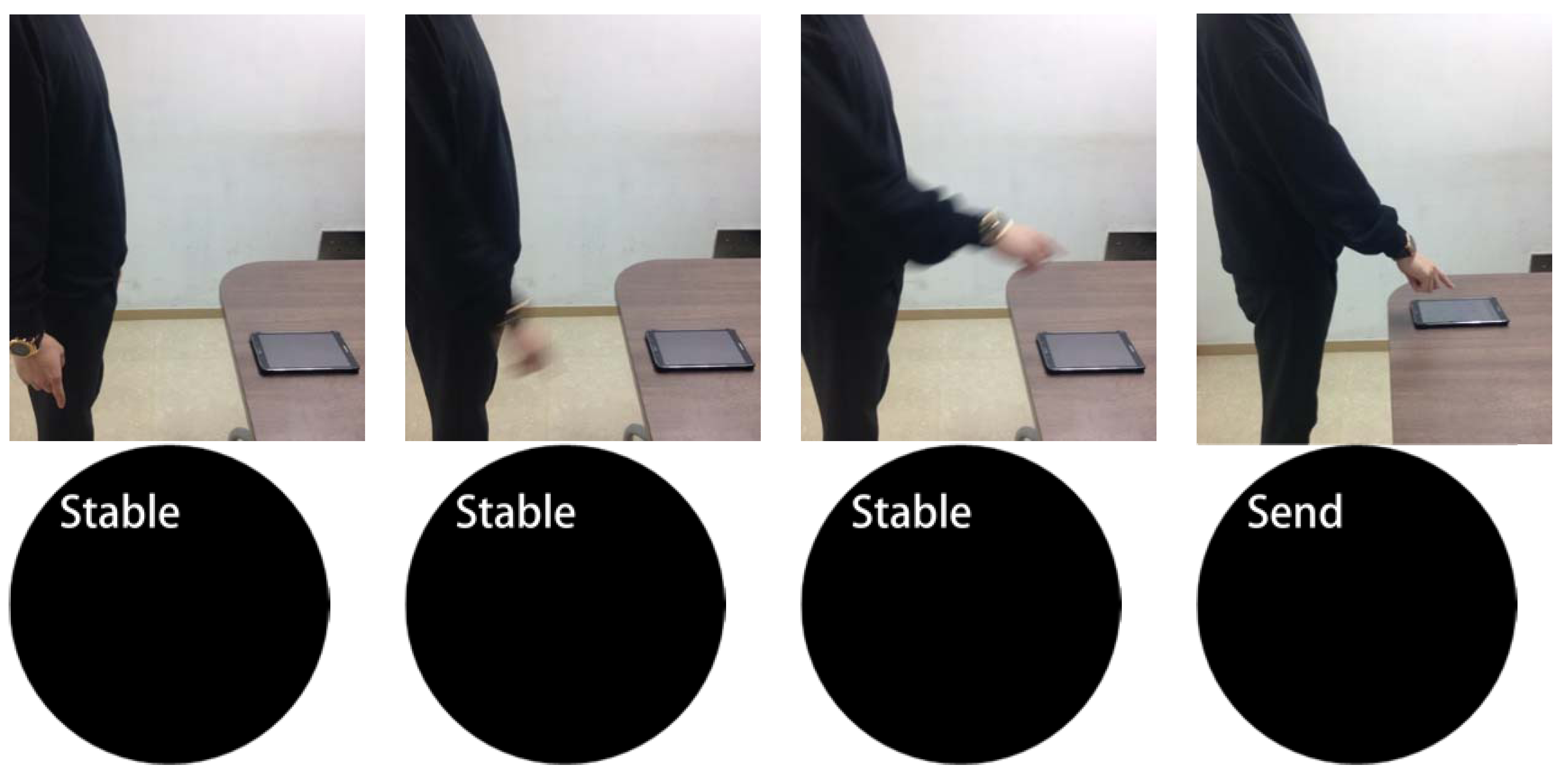
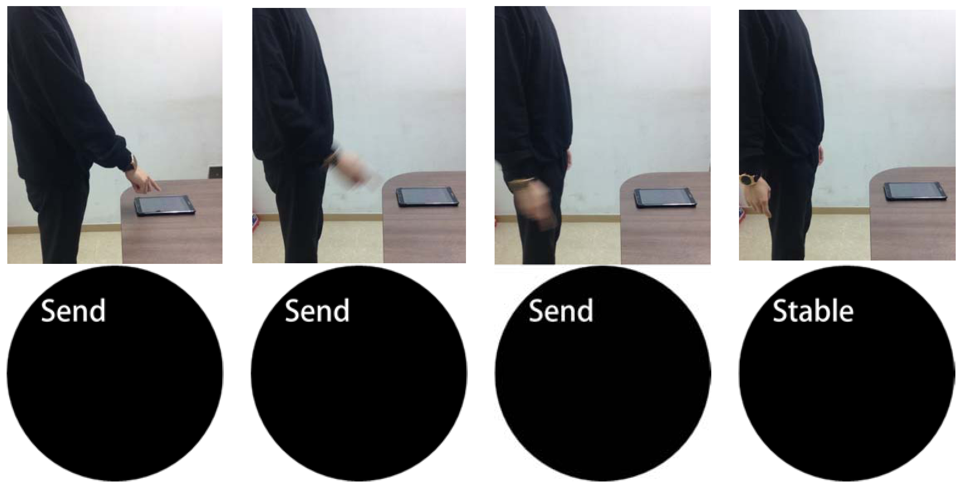
2.1. Identifying User Behaviors
- Raise the arm
- Take the actions to input a password
- Lower the arm
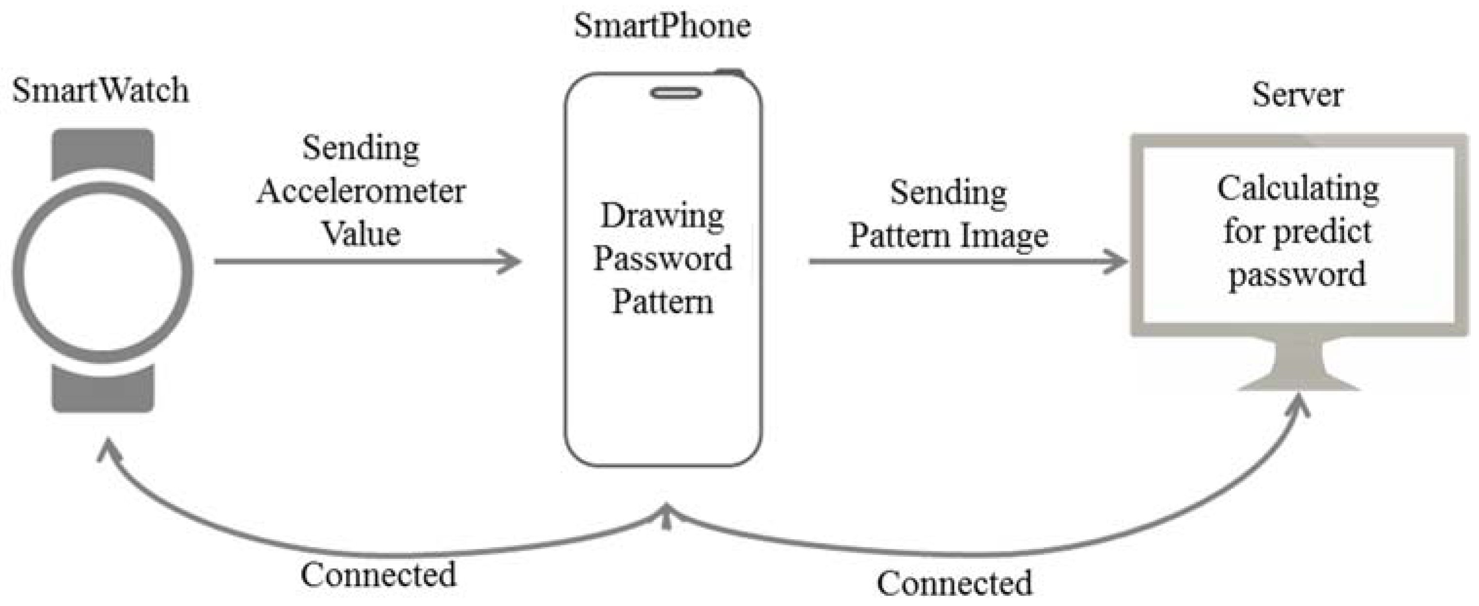
2.2. Start Transmission and Measurement Values
2.3. Transmission of Sensor Measured Values
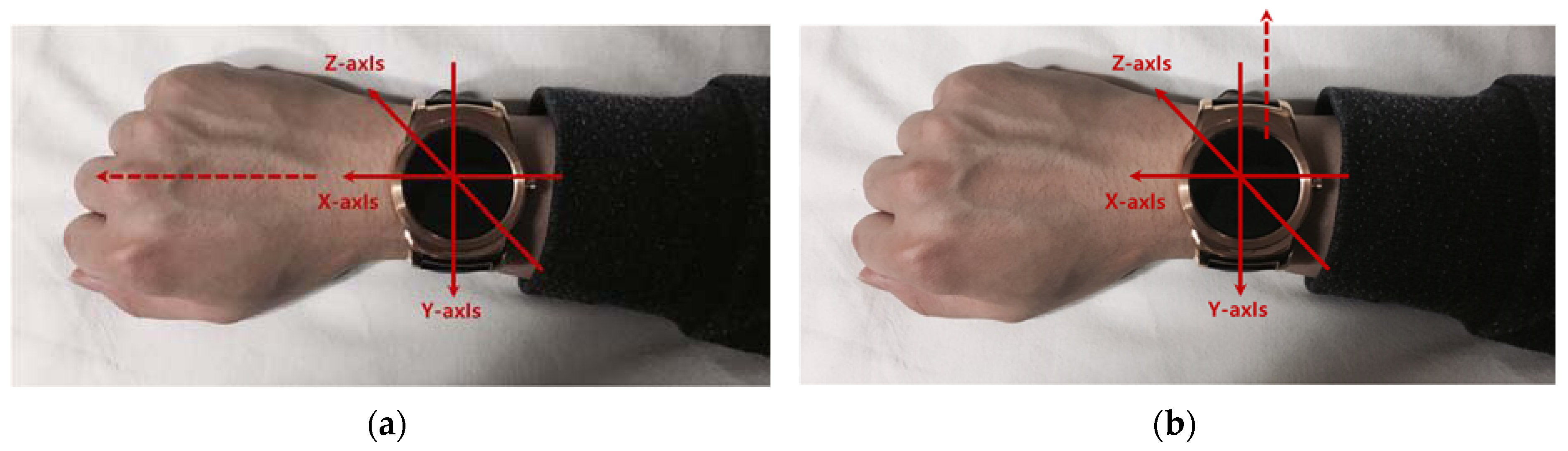
2.3.1. Acceleration Sensor
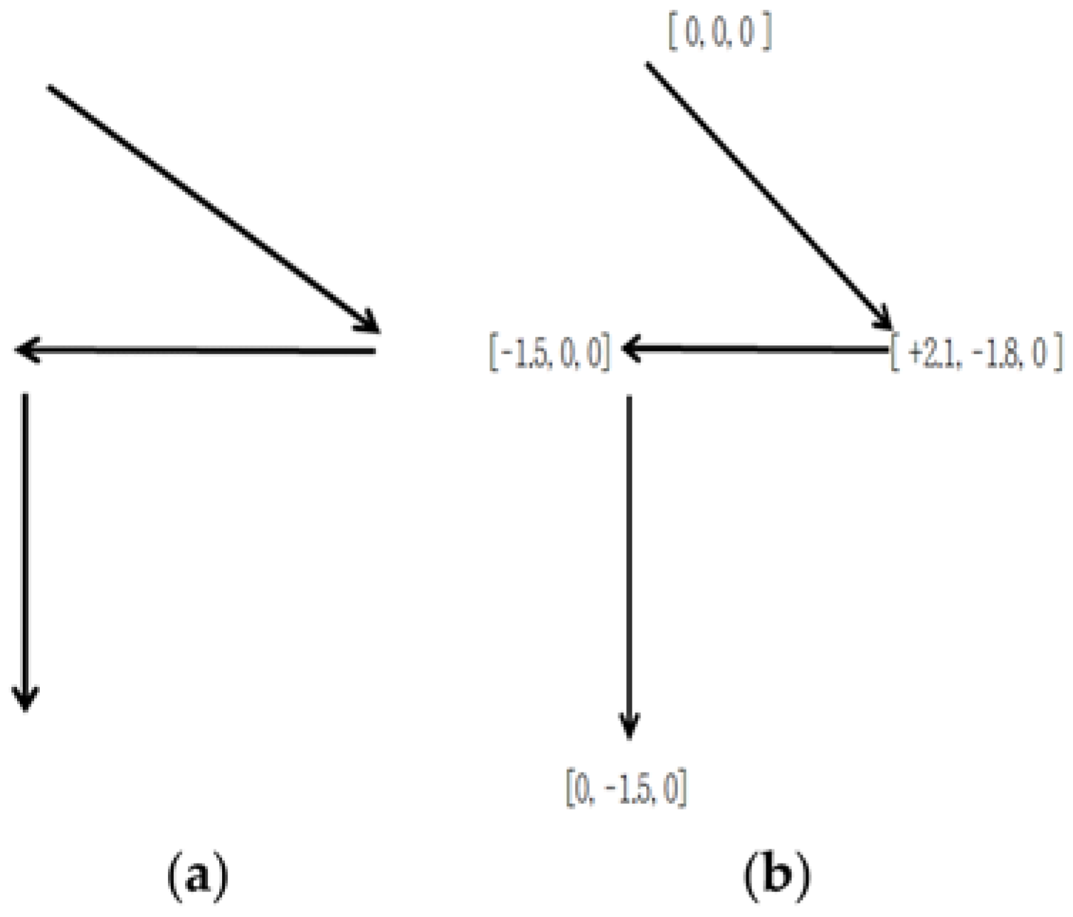
2.3.2. Simple Movements of Smartwatches in the Process of Inputting Passwords
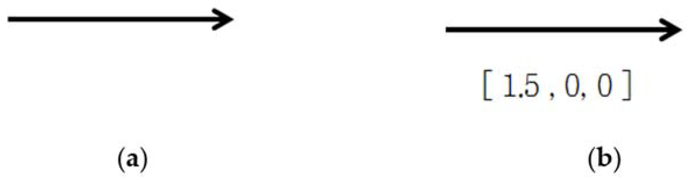
2.3.3. Smartwatch Movements when Password Pressing Actions are Taken
2.4. Terminate Transmission a Measurement Values
2.5. Password Estimation
2.6. Computational Complexity
2.7. Filter and Inertia
2.7.1. Low-Pass Filter
2.7.2. Kalman Filter
2.7.3. Inertia
3. Experiment
3.1. Experimental Environment
3.2. Scenario
3.3. Test Case
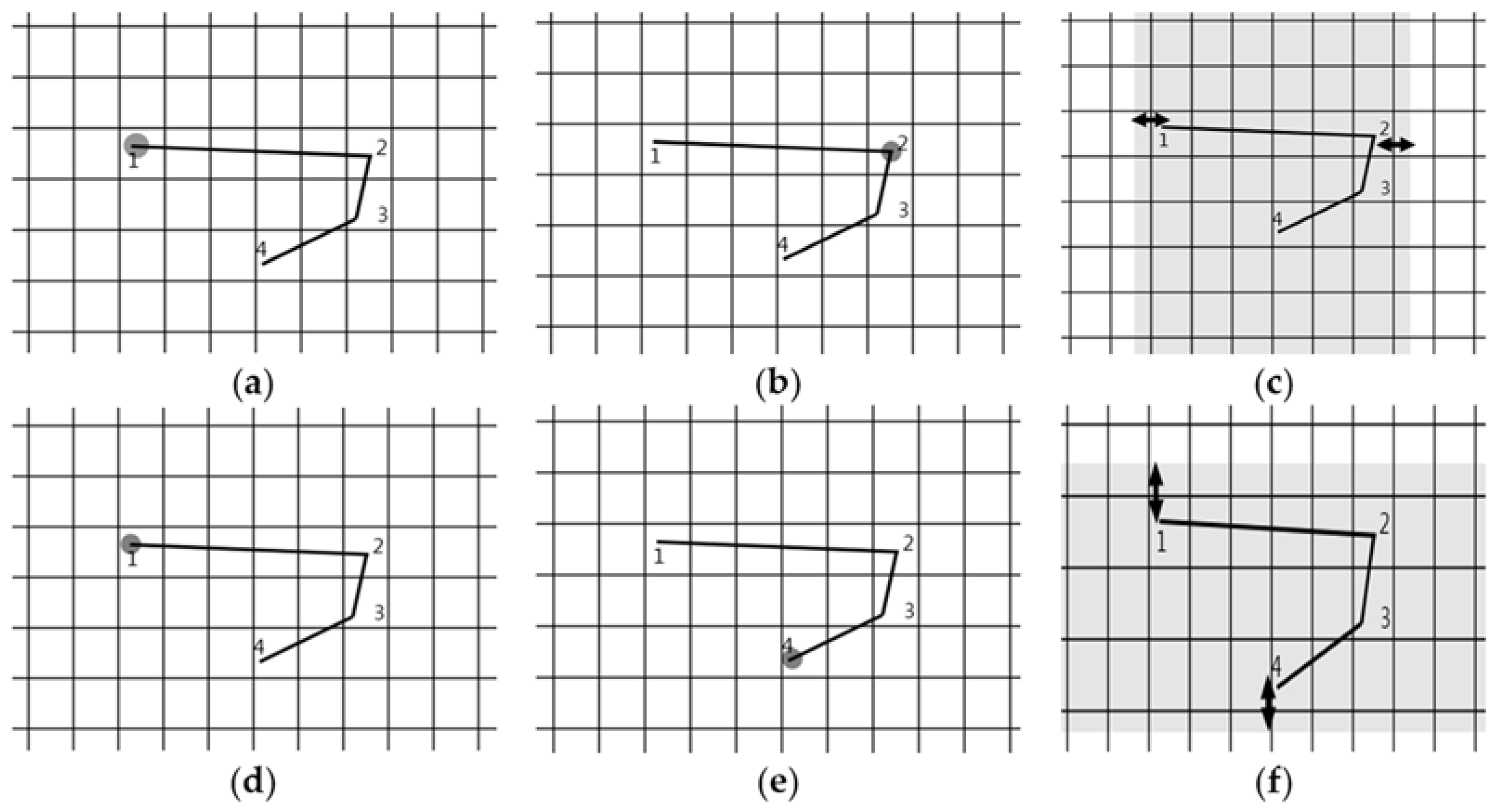
3.4. Pattern Acquisition
3.5. Pattern Acquisition by Angle Change
3.6. Results of Password Estimation
4. Verification
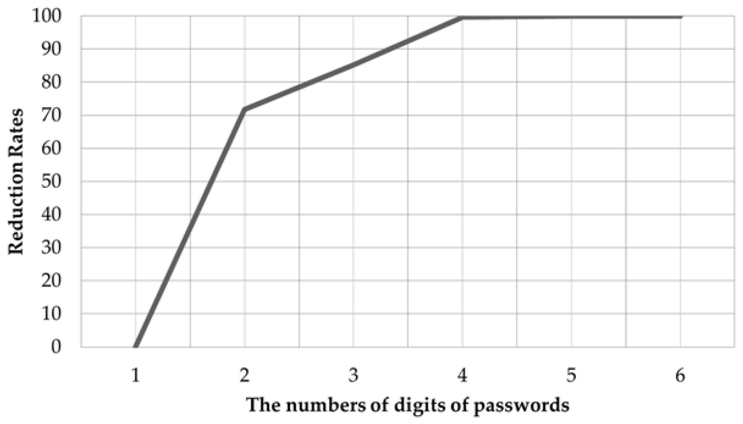
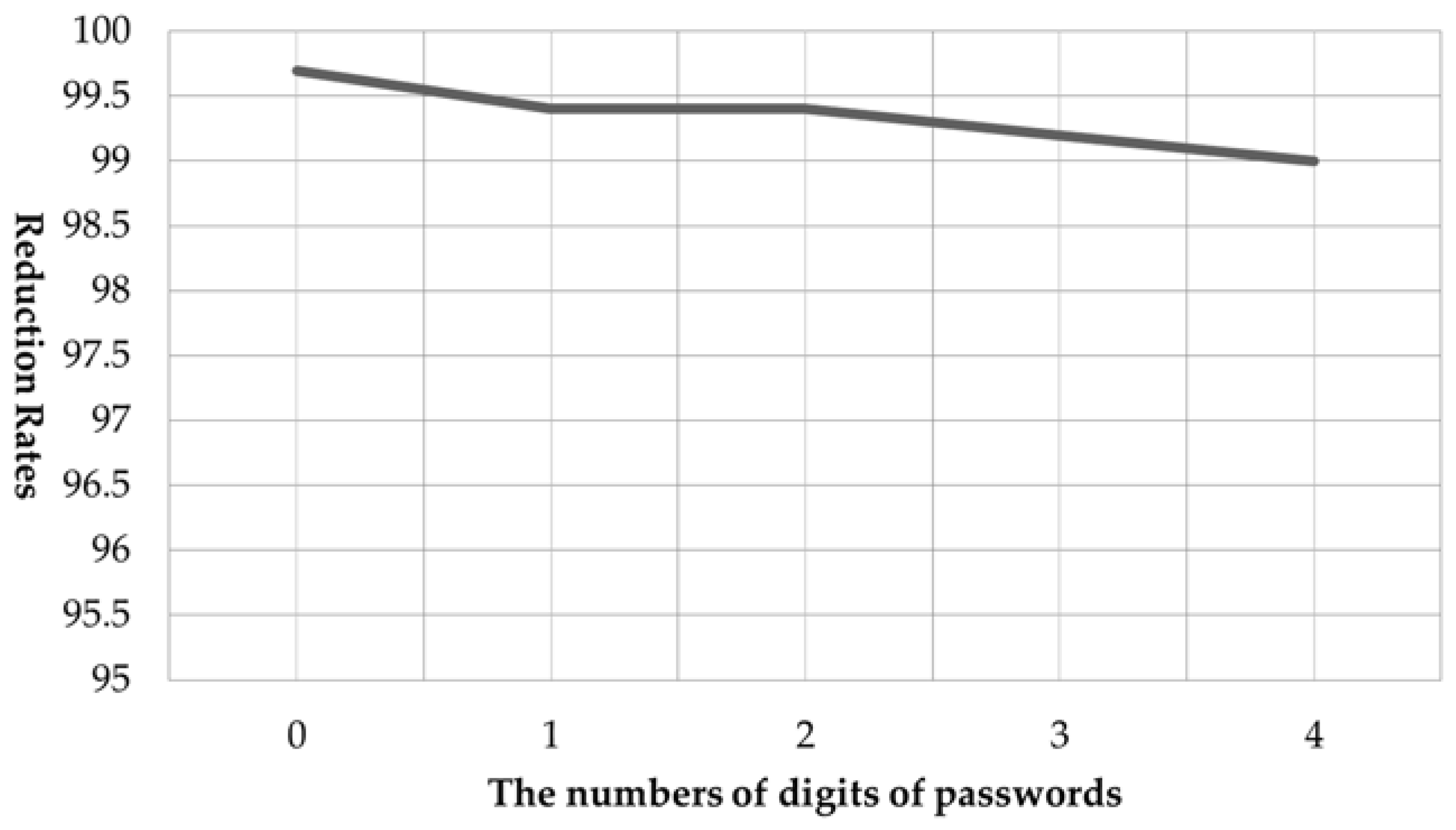
4.1. Reduction Rates for Number of Cases by the Number of Digits of Passwords
4.2. Reduction Rates for Number of Cases by the Number of Overlapping Digits
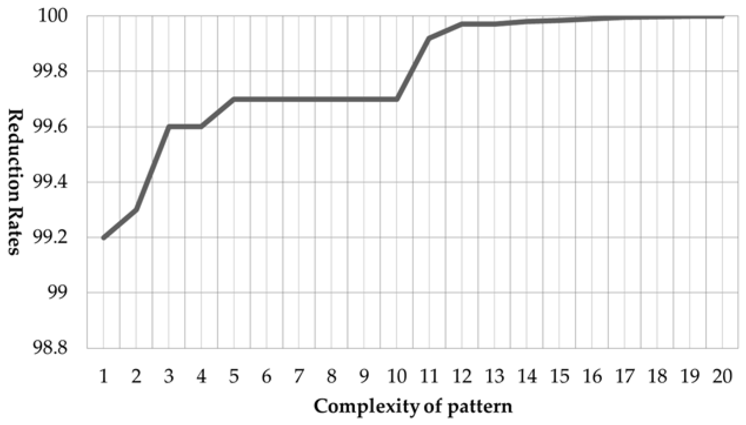
4.3. Reduction Rates for the Number of Cases According to Pattern Complexity
4.4. Binary Classification Result
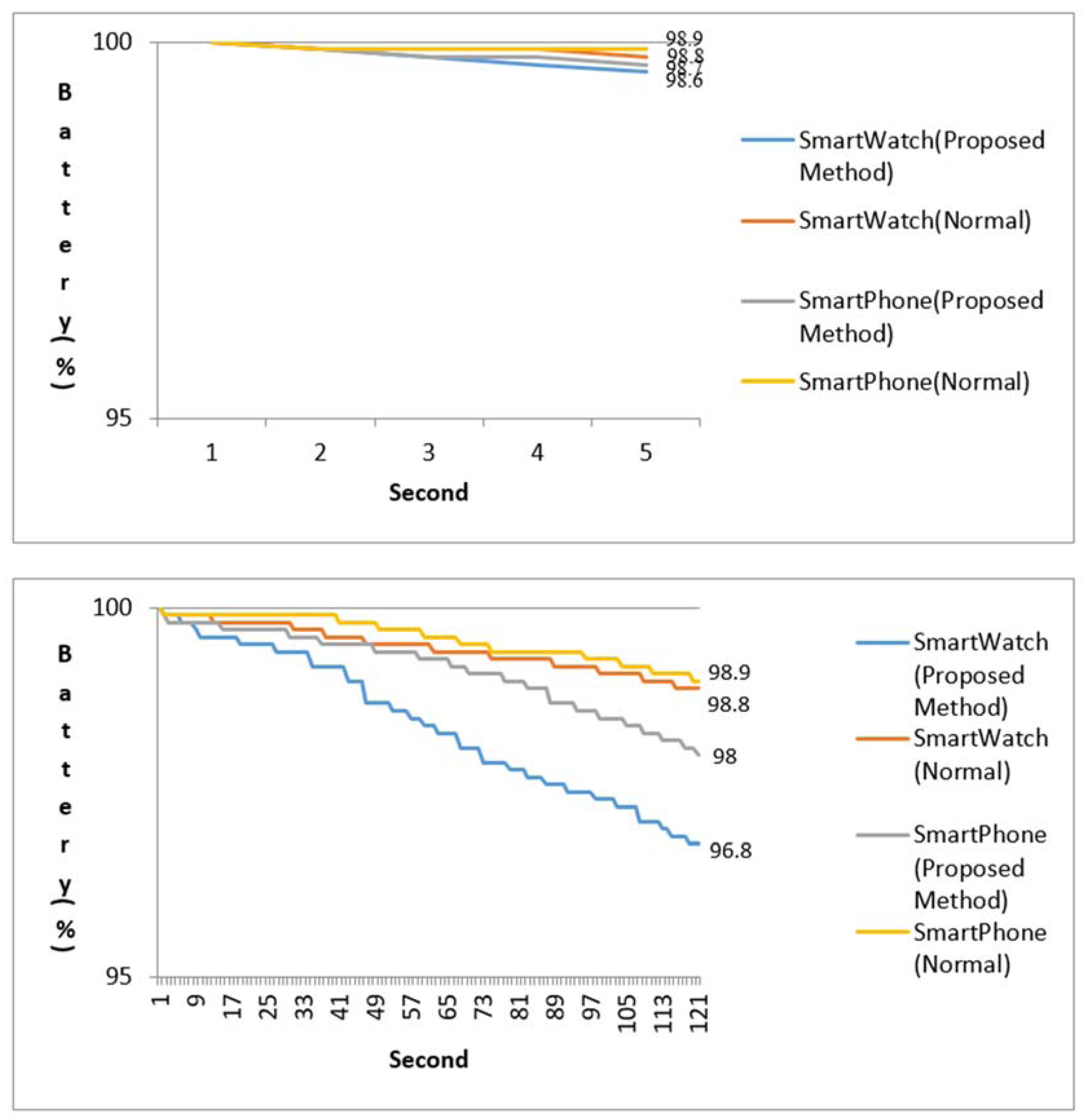
4.5. Energy Efficient
5. Related Work
6. Conclusion
Acknowledgments
Author Contributions
Conflicts of Interest
References
- Rawassizadeh, R.; Price, B.A.; Petre, M. Wearables: Has the age of smartwatches finally arrived? Commun. ACM 2015, 58, 45–47. [Google Scholar] [CrossRef]
- Chernbumroong, S.; Atkins, S.A.; Yu, H. Activity classification using a single wrist-worn accelerometer. In Proceedings of the 5th International Conference on Software, Knowledge Information, Industrial Management and Applications (SKIMA), Benevento, Italy, 8–11 September 2011. [Google Scholar]
- Hinckley, K.; Pierce, J.; Sinclair, M.; Horvitz, E. Sensing techniques for mobile interaction. In Proceedings of the 13th Annual ACM Symposium on User Interface Software and Technology, San Diego, CA, USA, 6–8 November 2000. [Google Scholar]
- Rawassizadeh, R.; Tomitsch, M.; Nourizadeh, M.; Momeni, E.; Peery, A.; Ulanova, L.; Pazzani, M. Energy-Efficient Integration of Continuous Context Sensing and Prediction into Smartwatches. Sensors 2015, 15, 22616–22645. [Google Scholar] [CrossRef] [PubMed]
- Udoh, E.S.; Alkharashi, A. Privacy risk awareness and the behavior of smartwatch users: A case study of Indiana University students. In Proceedings of the Future Technologies Conference (FTC), San Francisco, CA, USA, 6–7 December 2016. [Google Scholar]
- A PowerPoint Presentation by Paul E. Tippens, Professor of Physics Southern Polytechnic State University, 2017. Technical Paper. Available online: https://www.stcharlesprep.org/01_parents/vandermeer_s/Useful%20Links/Honors%20Physics/pdf%20lectures/Acceleration.pdf (accessed on 29 June 2017).
- Dadafshar, M. Accelerometer and Gyroscopes Sensors: Operation, Sensing, and Applications; Maxim Integrated: San Jose, CA, USA, 2014. [Google Scholar]
- The Earth’s Gravitational Field. Techinical Paper. Available online: http://www-gpsg.mit.edu/12.201_12.501/BOOK/chapter2.pdf (accessed on 29 June 2017).
- Takeda, R.; Tadano, S.; Todoh, M.; Morikawa, M.; Nakayasu, M.; Yoshinari, S. Gait analysis using gravitational acceleration measured by wearable sensors. J. Biomech. 2009, 42, 223–233. [Google Scholar] [CrossRef] [PubMed]
- Liu, M. A study of mobile sensing using smartphones. Int. J. Distrib. Sens. Netw. 2013. [Google Scholar] [CrossRef]
- Furutani, K.; Kato, M.; Tsuru, T. Low-Pass Filter. U.S. Patent 5,668,511, 16 September 1997. [Google Scholar]
- Welch, G.; Bishop, G. An Introduction to the Kalman Filter; University of North Carolina: Chapel Hill, NC, USA, 1995. [Google Scholar]
- LG Urbane. Available online: http://www.gsmarena.com/lg_watch_urbane_w150-7680.php (accessed on 29 June 2017).
- Samsung Galaxy S6. Available online: http://www.gsmarena.com/samsung_galaxy_s6-6849.php (accessed on 29 June 2017).
- Hardyck, C.; Petrinovich, L.F. Left-handedness. Psychol. Bull. 1977, 84, 385. [Google Scholar] [CrossRef] [PubMed]
- Watch Handedness. Available online: https://en.wikipedia.org/wiki/Watch#Handedness (accessed on 29 June 2017).
- Is It Acceptable to Wear a Watch on the Right Wrist? Available online: http://www.askandyaboutclothes.com/forum/showthread.php?116570-Is-it-acceptable-to-wear-a-watch-on-the-right-wrist (accessed on 29 June 2017).
- Why Wear a Watch on the Wrist Where You’re Hand Dominant? Available online: http://www.reddit.com/r/Watches/comments/1wzub5/question_why_wear_a_watch_on_the_wrist_where/ (accessed on 29 June 2017).
- Annett, M. Handedness and Brain Asymmetry: The Right Shift Theory; Psychology Press: Leicester, UK, 2002. [Google Scholar]
- Yan, S.; Soh, P.J.; Vandenbosch, G.A.E. Wearable dual-band composite right/left-handed waveguide textile antenna for WLAN applications. Electron. Lett. 2014, 50, 424–426. [Google Scholar] [CrossRef]
- Why Don’t Apple Have Left Handed Watches? Available online: https://www.iphonetricks.org/5-reasons-to-wear-the-apple-watch-on-your-left-hand/ (accessed on 29 June 2017).
- Android Wear Left Handed Mode? Available online: https://www.reddit.com/r/AndroidWear/comments/3f77fs/left_handed_mode/ (accessed on 29 June 2017).
- How to Set Up the Apple Watch for Left-Handed Use. Available online: http://www.imore.com/how-set-apple-watch-left-handed-use (accessed on 29 June 2017).
- Goutte, C.; Gaussier, E. A probabilistic interpretation of precision, recall and F-score, with implication for evaluation. In Proceedings of the European Conference on Information Retrieval, Santiago de Compostela, Spain, 21–23 March 2005. [Google Scholar]
- Nahapetian, A. Side-Channel Attacks on Mobile and Wearable Systems. In Proceedings of the 13th IEEE Annual Consumer Communications and Networking Conference (CCNC), Las Vegas, NV, USA, 9–12 January 2016. [Google Scholar]
- Spreitzer, R.; Moonsamy, V.; Korak, T.; Mangard, S. Systematic Classification of Side-Channel Attacks: A Case Study for Mobile Devices. 2010; arXiv:1611.03748. [Google Scholar]
- Chu, H.; Raman, V.; Shen, J.; Kansal, A.; Bahl, V.; Choudhury, R.R. I am a smartphone and I know my user is driving. In Proceedings of the 2014 Sixth International Conference on Communication Systems and Networks (COMSNETS), Bangalore, India, 6–10 January 2014. [Google Scholar]
- Cai, L.; Machiraju, S.; Chen, H. Defending against sensor-sniffing attacks on mobile phones. In Proceedings of the 1st ACM Workshop on Networking, Systems, and Applications for Mobile Handhelds, Barcelona, Spain, 17 August 2009. [Google Scholar]
- Cai, L.; Chen, H. TouchLogger: Inferring Keystrokes on Touch Screen from Smartphone Motion. In Proceedings of the 6th USENIX conference on Hot topics in security, San Francisco, CA, USA, 8–12 August 2011. [Google Scholar]
- Liang, C.; Chen, H. On the practicality of motion based keystroke inference attack. In Proceedings of the International Conference on Trust and Trustworthy Computing, Vienna, Austria, 13–15 June 2012. [Google Scholar]
- Xu, Z.; Bai, K.; Zhu, S. Taplogger: Inferring user inputs on smartphone touchscreens using on-board motion sensors. In Proceedings of the fifth ACM conference on Security and Privacy in Wireless and Mobile Networks, Tucson, AZ, USA, 16–18 April 2012. [Google Scholar]
- Owusu, E.; Han, J.; Das, S.; Perrig, A.; Zhang, J. ACCessory: Password inference using accelerometers on smartphones. In Proceedings of the Twelfth Workshop on Mobile Computing Systems & Applications, San Diego, CA, USA, 28–29 February 2012. [Google Scholar]
- Wang, H.; Lai, T.T.-T.; Choudhury, R.R. Mole: Motion leaks through smartwatch sensors. In Proceedings of the 21st Annual International Conference on Mobile Computing and Networking, Paris, France, 7–11 September 2015. [Google Scholar]
- Sarkisyan, A.; Debbiny, R.; Nahapetian, A. WristSnoop: Smartphone PINs prediction using smartwatch motion sensors. In Proceedings of the 2015 IEEE International Workshop on Information Forensics and Security (WIFS), Rome, Italy, 16–19 November 2015. [Google Scholar]
- Beltramelli, T.; Risi, S. Deep-Spying: Spying Using Smartwatch and Deep Learning. Master’s Thesis, IT University of Copenhagen, Copenhagen, Denmark, December 2015. [Google Scholar]
- Liu, X.; Zhou, Z.; Diao, W.; Li, Z.; Zhang, K. When good becomes evil: Keystroke inference with smartwatch. In Proceedings of the 22nd ACM SIGSAC Conference on Computer and Communications Security, Denver, CO, USA, 12–16 October 2015. [Google Scholar]
- SANS Technology Institute. Password Policy. Available online: https://www.sans.edu/student-files/projects/password-policy-updated.pdf (accessed on 29 June 2017).


| State | Explanation |
|---|---|
| Stable | The measured values were not transmitted. |
| Send | The measured values were transmitted. |
| Estimated Number | |||||
|---|---|---|---|---|---|
| First and second | (1, 3) | (1, 3) | (1, 3) | (4, 6) | (7, 9) |
| Third | 6 | 6 | 9 | 9 | ← |
| Fourth | 8 | 0 | 0 | 0 | none |
| Finally estimated number | 1368 | 1360 | 1390 | 4690 | none |
| Test Case | Password | Characteristics of the Patterns |
|---|---|---|
| 1 | 1234 | horizontal |
| 2 | 2580 | vertical |
| 3 | 1333 | horizontal, overlapping |
| 4 | 2000 | vertical, overlapping |
| 5 | 1399 | ㄱ-shaped, overlapping |
| 6 | 1357 | horizontal, diagonal |
| 7 | 1733 | vertical, diagonal |
| 8 | 7597 | triangle |
| 9 | 9054 | random |
| 10 | 8642 | random |
| 11 | 75920 | 5-digits |
| 12 | 39547 | 5-digits |
| 13 | 13333 | 5-digits |
| 14 | 10000 | 5-digits |
| 15 | 79831 | 5-digits |
| 16 | 976154 | 6-digits |
| 17 | 391736 | 6-digits |
| 18 | 798105 | 6-digits |
| 19 | 800000 | 6-digits |
| 20 | 139712 | 6-digits |
| Test Case | Password | Characteristics of the Patterns | Acquired Patterns | Test Case | Password | Characteristics of the Patterns | Acquired Patterns |
|---|---|---|---|---|---|---|---|
| 1 | 1234 | horizontal |  | 11 | 75920 | 5-digits |  |
| 2 | 2580 | vertical |  | 12 | 39547 | 5-digits |  |
| 3 | 1333 | horizontal, overlapping |  | 13 | 13333 | 5-digits |  |
| 4 | 2000 | vertical, overlapping |  | 14 | 10000 | 5-digits |  |
| 5 | 1399 | ㄱ-shaped, overlapping |  | 15 | 79831 | 5-digits |  |
| 6 | 1357 | horizontal, diagonal |  | 16 | 976154 | 6-digits |  |
| 7 | 1733 | vertical, diagonal |  | 17 | 391736 | 6-digits |  |
| 8 | 7597 | triangle |  | 18 | 798105 | 6-digits |  |
| 9 | 9054 | random |  | 19 | 800000 | 6-digits |  |
| 10 | 8642 | random |  | 20 | 139712 | 6-digits |  |
| Tablet Angle | Acquired Patterns | Tablet Angle | Acquired Patterns | Tablet Angle | Acquired Patterns |
|---|---|---|---|---|---|
| 0° |  | 10° |  | 20° | 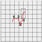 |
| 30° | 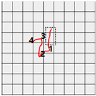 | 40° | 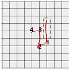 | 50° | 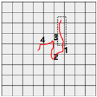 |
| Test Case | Password | Characteristics of the Patterns | Estimated Passwords | Estimation Success Rate |
|---|---|---|---|---|
| 1 | 1234 | horizontal | 1234, 4560, 7890 | 100 |
| 2 | 2580 | vertical | 1470, 2580, 3690 | 100 |
| 3 | 1333 | horizontal, overlapping | 1222, 1333, 4555, 4666, 7888, 7999, 0000 | 100 |
| 4 | 2000 | vertical, overlapping | 1444, 1777, 1000, 2555, 2888, 2000, 3666, 3999 | 100 |
| 5 | 1399 | ㄱ-shaped, overlapping | 1255, 1288, 1366, 1399 | 100 |
| 6 | 1357 | horizontal, diagonal | 1357, 1350, 4680 | 100 |
| 7 | 1733 | vertical, diagonal | 1733, 1766, 4033, 4066 | 100 |
| 8 | 7597 | triangle | 4264, 7297, 7597 | 100 |
| 9 | 9054 | random | 6821, 6021, 9054 | 100 |
| 10 | 8642 | random | 0975, 0972, 8642 | 100 |
| 11 | 75920 | 5-digits | 75920 | 100 |
| 12 | 39547 | 5-digits | 39547, 39540 | 100 |
| 13 | 13333 | 5-digits | 13333, 46666, 79999, | 100 |
| 14 | 10000 | 5-digits | 14444, 17777, 10000, 25555, 28888, 20000 3666, 39999 | 100 |
| 15 | 79831 | 5-digits | 46531, 79831, 79864 | 100 |
| 16 | 976154 | 6-digits | 976154 | 100 |
| 17 | 391736 | 6-digits | 281714, 391736, 392825 | 100 |
| 18 | 798105 | 6-digits | 798105 | 100 |
| 19 | 800000 | 6-digits | 144444, 177777, 100000, 200000, 255555, 288888, 366666, 399999 400000, 4777777, 500000, 588888, 699999, 700000, 800000 | 100 |
| 20 | 139712 | 6-digits | 136412, 139012, 139712, 469745 | 100 |
| Test Case | Password | No. of Digits | Characteristics of the Patterns | Total Number of Cases of Passwords | Number of Estimated Password | Number of Cases Reduction Rate |
|---|---|---|---|---|---|---|
| 1 | 1234 | 4 | horizontal | 1000 | 3 | 99.700 |
| 2 | 2580 | 4 | vertical | 1000 | 3 | 99.700 |
| 3 | 1333 | 4 | horizontal, overlapping | 1000 | 7 | 99.300 |
| 4 | 2000 | 4 | vertical, overlapping | 1000 | 8 | 99.200 |
| 5 | 1399 | 4 | ㄱ-shaped, overlapping | 1000 | 4 | 99.600 |
| 6 | 1357 | 4 | horizontal, diagonal | 1000 | 3 | 99.700 |
| 7 | 1733 | 4 | vertical, diagonal | 1000 | 4 | 99.600 |
| 8 | 7597 | 4 | triangle | 1000 | 3 | 99.700 |
| 9 | 9054 | 4 | random | 1000 | 3 | 99.700 |
| 10 | 8642 | 4 | random | 1000 | 3 | 99.700 |
| 11 | 75920 | 5 | random | 10,000 | 1 | 99.990 |
| 12 | 39547 | 5 | random | 10,000 | 2 | 99.980 |
| 13 | 13333 | 5 | horizontal, overlapping | 10,000 | 3 | 99.970 |
| 14 | 10000 | 5 | vertical, overlapping | 10,000 | 8 | 99.920 |
| 15 | 79831 | 5 | Random | 10,000 | 3 | 99.970 |
| 16 | 976154 | 6 | Random | 100,000 | 1 | 99.999 |
| 17 | 391736 | 6 | Random | 100,000 | 3 | 99.997 |
| 18 | 798105 | 6 | Random | 100,000 | 1 | 99.999 |
| 19 | 800000 | 6 | vertical, overlapping | 100,000 | 15 | 99.985 |
| 20 | 139712 | 6 | random | 100,000 | 4 | 99.996 |
| Test Case | Password | Predicted Passwords | Numbers of Predicted Passwords | Precision | Recall Factor | F-Score |
|---|---|---|---|---|---|---|
| 1 | 1234 | 1234, 4560, 7890 | 3 | 0.333 | 1.000 | 0.500 |
| 2 | 2580 | 1470, 2580, 3690 | 3 | 0.333 | 1.000 | 0.500 |
| 3 | 1333 | 1222, 1333, 4555, 4666, 7888, 7999, 0000 | 7 | 0.143 | 1.000 | 0.250 |
| 4 | 2000 | 1444, 1777, 1000, 2555, 2888, 2000, 3666, 3999 | 8 | 0.125 | 1.000 | 0.222 |
| 5 | 1399 | 1255, 1288, 1366, 1399 | 4 | 0.250 | 1.000 | 0.400 |
| 6 | 1357 | 1357, 1350, 4680 | 3 | 0.333 | 1.000 | 0.500 |
| 7 | 1733 | 1733, 1766, 4033, 4066 | 4 | 0.250 | 1.000 | 0.400 |
| 8 | 7597 | 4264, 7297, 7597 | 3 | 0.333 | 1.000 | 0.500 |
| 9 | 9054 | 6821, 6021, 9054 | 3 | 0.333 | 1.000 | 0.500 |
| 10 | 8642 | 0975, 0972, 8642 | 3 | 0.333 | 1.000 | 0.500 |
| 11 | 75920 | 75920 | 1 | 1.000 | 1.000 | 1.000 |
| 12 | 39547 | 39547, 39540 | 2 | 0.500 | 1.000 | 0.667 |
| 13 | 13333 | 13333, 46666, 79999 | 3 | 0.333 | 1.000 | 0.500 |
| 14 | 10000 | 14444, 17777, 10000, 25555, 28888, 20000 36666, 39999 | 8 | 0.125 | 1.000 | 0.222 |
| 15 | 79831 | 46531, 79831, 79864 | 3 | 0.333 | 1.000 | 0.500 |
| 16 | 976154 | 976154 | 1 | 1.000 | 1.000 | 1.000 |
| 17 | 391736 | 281714, 391736, 392825 | 3 | 0.333 | 1.000 | 0.500 |
| 18 | 798105 | 798105 | 1 | 1.000 | 1.000 | 1.000 |
| 19 | 800000 | 144444, 177777, 100000, 200000, 255555, 288888, 366666, 399,999 400,000, 4777777, 500000, 588888, 699999, 700000, 800000 | 15 | 0.067 | 1.000 | 0.125 |
| 20 | 139712 | 136412, 139012, 139712, 469745 | 4 | 0.250 | 1.000 | 0.400 |
© 2017 by the authors. Licensee MDPI, Basel, Switzerland. This article is an open access article distributed under the terms and conditions of the Creative Commons Attribution (CC BY) license (http://creativecommons.org/licenses/by/4.0/).
Share and Cite
Kim, J.; Youn, J.M. Threats of Password Pattern Leakage Using Smartwatch Motion Recognition Sensors. Symmetry 2017, 9, 101. https://doi.org/10.3390/sym9070101
Kim J, Youn JM. Threats of Password Pattern Leakage Using Smartwatch Motion Recognition Sensors. Symmetry. 2017; 9(7):101. https://doi.org/10.3390/sym9070101
Chicago/Turabian StyleKim, Jihun, and Jonghee M. Youn. 2017. "Threats of Password Pattern Leakage Using Smartwatch Motion Recognition Sensors" Symmetry 9, no. 7: 101. https://doi.org/10.3390/sym9070101
APA StyleKim, J., & Youn, J. M. (2017). Threats of Password Pattern Leakage Using Smartwatch Motion Recognition Sensors. Symmetry, 9(7), 101. https://doi.org/10.3390/sym9070101