1. Introduction
With the rapid growth of mobile data services, the requirement for the communication speed and communication quality in today’s wireless communication system is increasing constantly [
1]. High speed, high spectral efficiency, high capacity and high reliability will be the dominant factors of modern communication system [
2]. However, with increasingly complex wireless communication environment, channel fading caused by multipath propagation [
3] is becoming more and more serious. At the same time, traditional multiplex communication technologies (frequency division multiplexing, time division multiplexing, code division multiplexing) are becoming increasingly difficult to cope with the tense situation of spectrum resources [
4,
5,
6]. Under such circumstances, the MIMO system is put forward to solve the problem. The multipath signal transmission in traditional communication theory has always been the negative factor [
7]; however, the MIMO technology can make full use of the multipath fading in the free space and exponentially increases the system transmission rate and the communication capacity [
8]. Communication quality has been greatly improved for the limited spectrum resources and fixed transmit power by this technology [
9].
The most prominent advantage of MIMO systems is that it can increase channel capacity and spectrum efficiency without increasing bandwidth and antenna transmit power [
10], which will maximize the spatial multiplexing gain and diversity gain. In fact, the nature of improving the spatial multiplexing gain is to maximize the spectrum utilization and improve channel capacity by introducing multi antennas [
11,
12]. The nature of improving the diversity gain is to improve the channel reliability and reduce the system bit error rate by time-space encoding [
13]. However, in MIMO communication technology, there are still some defects that limit development. First, in order to increase the spatial reuse of the MIMO system, the correlation between the MIMO channels and the mutual coupling between multi-antennas should be reduced as much as possible. However, the antenna dimension usually increases to at least half a wavelength and it is difficult to realize such large feed structure in the portable terminal device. Second, the MIMO system needs to equip the transmit antennas and receive antennas with a radio link, and the high cost and high power consumption in the amplifier and mixer will increase the overall system complexity. Therefore, improvement of the efficiency of the corresponding feeder system and simplification of the RF link in the MIMO system is a challenging issue in the field of MIMO technology.
In order to reduce channel dependence, the decoupling network [
14,
15] was used to ensure the isolation between antennas, but the network design is complex and the system bandwidth is too narrow. In order to simplify the RF link, the signal processing in the transmitter and receiver antenna will adopt the selection algorithm [
16]. The algorithm selects the best transmission performance antennas as the transmitter and the receivers using the RF switch [
17]. The antenna selection algorithm is considered to be the best when the system channel capacity reaches maximum [
18]. In [
19], a method for source separation based on the single source point identification and time frequency-smoothed
l0 norm in non-cooperative electromagnetic case is proposed. In addition, some researchers have implemented space coding and time coding using spatial modulation [
20] or the beamforming algorithm [
21], which can be implemented in the RF domain and can effectively reduce the complexity of the system.
However, with the increasing size of the MIMO system, the number of RF links is still very large and the simplification of the RF link has not been fundamentally solved. The single-link MIMO system based on SPA was proposed [
22,
23]. In the system, the transmitting antenna adopts a planar SPA structure with three elements, and the distance between antennas is 1/12 propagation wavelength, which breaks through the limitation of half a wavelength of the traditional 2 × 2 MIMO system. The experimental results show that the changing tendency of error rate with the signal-to-noise ratio shares the same regularity with traditional MIMO system. The single RF link MIMO system can not only guarantee the performance of traditional MIMO, but greatly reduces the complexity of the system and the power loss, which realizes the miniaturization of the antenna. The spatial multiplexing of MIMO system can be realized through the SPA switched far field patterns, but the process of far field pattern fails in the hardware realization. Subsequently, the theory of using switching parasitic antennas to achieve the diversity of far field radiation pattern has gradually been improved [
24,
25].
Now, in 2 × 2 MIMO systems, the space between the two switching parasitic antennas can reach 1/16 of the wavelength [
26]. It is worth noting that three elements can achieve two radiation patterns conversion in a 2 × 2 MIMO system. If the MIMO system size increased by one, then the number of the switched parasitic antenna will increase by two [
27], which requires all parasitic elements around the feeding unit to be evenly arranged, and leads to an increase in space. In conclusion, a large single RF link MIMO system based on the switched parasitic antenna is more suitable for the base station rather than the portable terminal, especially for cognitive radio applications [
28].
In this paper, system level simulation was established in SystemVue software and the performance of single RF link MIMO system was analyzed comprehensively. The SystemVue software can provide rich design modules and an open environment for complex algorithm development and system level analysis of digital signal processing, and it also has the ability to generate real signal system for testing and verification with the help of all kinds of Agilent signal sources. Therefore, it is suitable for the situation in this paper to implement the system-level simulation that can directly evaluate the component characteristics that have an influence on the overall performance of the system.
The rest of this paper is organized as follows.
Section 2 introduces the structure, principle, and key technologies of a single RF link MIMO system based on SPA. In
Section 3, the proposed single RF link MIMO system model was simulated in SystemVue software.
Section 4 presents the performance analysis of the single RF link MIMO system. Finally, the paper is concluded in
Section 5.
2. Theory of MIMO System
In this section, the theory of the single RF link MIMO system will be introduced. The structure, principle, and key technologies of the single RF link MIMO system introduced in this chapter are based on switched parasitic antenna structure.
2.1. Single Link MIMO System
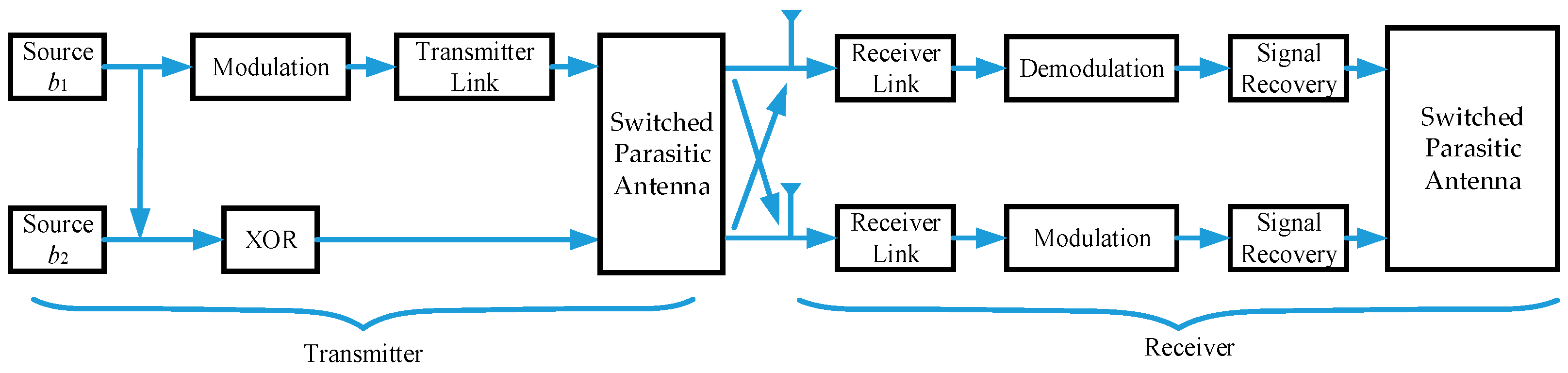
The basic structure of the single RF link of 2 × 2 MIMO system based on the switched parasitic antenna is shown in
Figure 1. From the view of the function, the single RF link MIMO system can be divided into two parts, the transmitter and the receiver. The original binary code was radiated through the switch parasitic antenna after a series of transformation to the RF signal. The receiver is the inverse process, which will convert the RF signal to the binary code. From the view of the signal, the whole system can be divided into baseband digital processing and analog RF processing. In the baseband, the signal will complete the generation and recovery process, and the RF part mainly involves signal transmission and reception. The baseband and RF processing are realized by a digital-to-analog converter (DAC) or analog-to-digital converter (ADC). The single RF link is concentrated in the transmitter, and receivers adopt the conventional uniform array antenna.
The core idea of a single RF link MIMO system based on switched parasitic antenna is to map multiple signals at the transmitter to a set of far field radiation patterns orthogonal to each other in free space. One channel of input is feed to the antenna after the modulation, frequency conversion and filtering process. The other input symbols are directly connected with the parasitic elements to control the state of varactor diodes loaded in parasitic elements, which will change the far field radiation pattern subsequently. The number of parasitic elements depends on the size of the MIMO system. As for 2 × 2 MIMO system, two far-field radiation patterns can be achieved by two elements. On the basis of this, for the N × N MIMO system, every increase in N will correspond to two more parasitic elements. It is worth mentioning that the varactor diode is introduced to achieve smooth transform of impedance and the performance have significantly improved compared with other diodes, such as Positive Intrinsic-Negative (PIN) diodes, but the external DC bias network is complex.
The load reactance value of the parasitic unit loaded on the antenna is directly controlled by the exclusive operation (XOR) of two input signal b1 and b2. It will change the current direction of the antenna structure and form multiple directional patterns. The transmitted signal of the transmitting antenna arrives at the receiving end of the system after mixing the Rayleigh channel with additive white Gauss noise. The task of the receiver is to recover two digital signals as quickly and accurately as possible. In the two branches of the antenna, the RF module is the same as the demodulation module, but the signal recovery module will process the two signals differently. The performance of the receiver will be measured by the accuracy of the recovered binary signal. The method is to measure the bit error rate by comparing the recovered bits with the input symbols at the transmitter.
The two mirror-symmetry directional functions are represented by
, which satisfies the condition
. The correlation can be expressed as:
and
represent the radiation power at the direction of
, respectively. When the parameters of the varactor loaded on the two parasitic units are the same (
), it means the two directions have achieved a state of balance. A diagonal function can be constructed on the premise that the
and
are mirror symmetry.
The correlation between
and
can be expressed as:
Therefore, when the known direction map and have mirror symmetry, the free space will naturally form a pair of mutually orthogonal angle functions, and . In the independent fading environment, the two signals emitted from the transmitting antennas will be independent from each other, which is a breakthrough in the traditional MIMO system for achieving the miniaturization design of the transmitter.
In
Figure 1, the first input binary code
b1 after BPSK modulation is denoted as
S1, then the antenna radiation patterns in the far field can be expressed as Equation (7) or Equation (8):
If we combine Equations (7) and (8), the radiation can also be expressed as:
In Equation (9),
S represents the state of the antenna. When
S = 1, the far-field radiation pattern of the transmitting antenna is
, and when
S = 2, the far-field radiation pattern of antenna is
. It can be found in [
29] that arbitrary PSK signals are suitable for the antenna structure, and
s2 is a group of complex numbers which are uniformly distributed on the unit circle.
In the single RF link 2 × 2 MIMO system, the relationship between the antenna status
S and the two input signals
b1 and
b2 is shown in
Table 1. In fact,
s1 and
s2 are the modulated values of
b1 and
b2, respectively. It can be concluded that
S is exactly equal to the XOR results of
b1 and
b2, indicating that the two binary signal
b1 and
b2 XOR results can form two states, and each state will correspond to far field radiation map of a switch parasitic antenna.
2.2. Channel Design
In the MIMO communication systems, signals transmitted from the antennas to the received antennas needs to pass through the wireless channels. In the transmission, it is impossible for the electromagnetic wave to realize the direct transmission from the transmitting antenna to the receiving antenna. The buildings, trees, cars, and pedestrians during the transmission will cause reflection, scattering, and attenuation, which forms the multipath effect [
30]. For a point from the receiving end, the final vibration presentation is the synthesis triggered by the multiple paths vibration, but the power required for each path vibration trigger is not necessarily the same. Besides, the vibration starting time can be different. In Equation (10),
is the power attenuation factor, and
and
present the emission signal and the delay, respectively. The whole vibration can be described as:
The closing formula represents the superposition of vibrations triggered by all paths. Multipath effects can be divided into two kinds: the objective multipath effect and the multipath effect with time resolution [
31]. For an objective multipath, the received signal can be represented as:
It can be seen from Equation (11) that for the inherent multipath effect, the final rendering effect is consistent with the effect of single path transmission. For a multipath effect with time resolution,
denotes different delays in each path. Normally, the multipath effect is time dependent, which can be described as a stochastic process of time and space, which satisfies certain statistical characteristics after a large number of field tests. The Rayleigh distribution is often used to describe the fading range of multipath signals in analog buildings with dense urban communication environments. The probability density function is:
It represents a stationary narrow-band Gauss random process with a mean value of 0 and a variance of
. When the ambient environment is simple and the transmitting antenna and the receiving antenna can realize direct path transmission, the Rician distribution is used to describe the fading range of the multipath signal. The Rician distribution can be regarded as the sum of the multipath signal components of the dominant signal and the Rayleigh distribution. The probability density function can be expressed as:
A denotes the peak signal amplitude and is the zero order Bessel function of the first order. Both the Rayleigh channel and Rician channel belong to fast fading channels. The specific channel fading factor at a specific time of the transmitter is unknown, but it is always changing and satisfies a certain probability distribution. In this paper, the Rayleigh channel model is adopted because the default communication environment is densely populated in urban areas.
2.3. Receiver Design
The algorithm introduced at the receiver is mainly for correcting the distortion introduced by the channel. Three receiver algorithms are presented, including the zero forcing algorithm, the maximum merge ratio algorithm, and the minimum mean square error algorithm. The core idea of the zero forcing algorithm is to use linear transformation matrix to multiply the receiver matrix, and it will completely or partially eliminate the interference of other antennas except the Gauss white noise. For the
t ×
r MIMO system, the relation between the received signal
Y of the receiving antenna, the transmitting signal
X of the transmitting antenna, the channel matrix
H, the interference
W, and the Gauss white noise
N can be described as:
It can be rewritten into the matrix format, as is shown in Equation (15).
A linear merging method can be found to eliminate interference
W, and the merging coefficients
needs to be found to satisfy:
Therefore, the middle product term should be zero.
Therefore, we need to find a vector orthogonal to in the r dimensional linear space. Based on the matrix theory, there are many solutions that are orthogonal to the w matrix.
From the linear space point of view, the zero forcing algorithm is to project the received signal to the orthogonal direction of interference, so that the interference becomes zero or approaches zero, which is the maximum signal to interference ratio (SIR). The principle of the maximum combination ratio algorithm is the projection of the received signal to a certain direction to ensure the maximum received signal-to-noise power ratio. For the
t ×
r MIMO system, the maximum combination ratio algorithm uses the weighted factor
to linearly combine the reception signal:
The
h matrix can be expressed as:
The independent high four noise does not change the projection length in any direction, and it owns the isotropic character. Therefore, as long as the received signal is projected to the signal direction, it will be fully matched to reach the maximum value.
The linear minimum mean square error algorithm combines the ideas of the first two algorithms to realize the maximum signal to interference-noise ratio. It can be found in Equation (14) that
X,
Z and
W are random variables, and
Y is a function of the three random variables. Based on
Y, the random variable
should make sure that the average distance between the random variables and the real
long-term statistics have the minimum average error. That is to say, in the moment of observed
, find a
to calculate the distance observed between
at moment one. Then, in the moment of observed
, find a
to calculate the distance observed between
at moment two. By this way, the observed sequence
will have the smallest average distance with the real-sent sequence
. A simpler and commonly used method is to use the linear representation of the components
of
Y, and the
will have the following format:
Thus we need to find a group of constants
to minimize (21):
According to the orthogonal principle, we can get:
By the expansion of inner product of random variables, the value of all
can be obtained according to (23):
For the above three algorithms, the zero forcing algorithm is most easily implemented if there is no correlation between the interference and the useful signal in the system. To a certain extent, it will amplify the system noise, but it can effectively eliminate the system interference. The combined ratio algorithm mainly focuses on useful information and the noise information of all sequences. The minimum mean square error algorithm lies on the effective transmission sequence and channel impulse response after the convolution, and will find the sequence that has the minimum distance from the received signal. The third algorithm performs better than the previous two, but the complexity also increases. In this paper, the zero forcing algorithm and the minimum mean square error algorithm are adopted to achieve channel equalization and reduce the system error rate.
3. Modeling of MIMO System in SystemVue
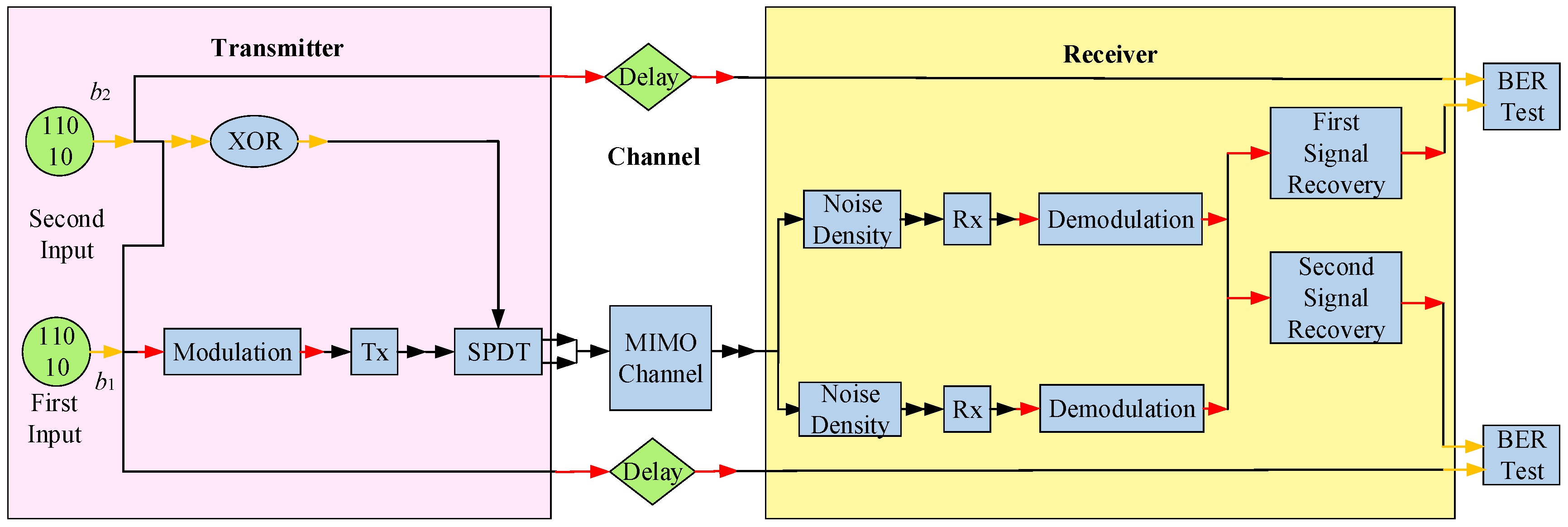
The EDA software SystemVue, developed by Agilent Cooperation (Santa Clara, CA, USA), is mainly used to implement electronic system level simulation. The overall architecture of a single RF link 2 × 2 MIMO system based on the switched parasitic antennas in SystemVue platform is shown in
Figure 2. The simulation setup can be exported to a real-time implementation for system verification. In a laboratory environment, the real system integration testing will capture the real signals with the aid of an instrument, and use these real signals that contain distortion to help design other modules. By the instrument connection options in SystemVue, it can be directly integrated with other DSP tools, such as ModelSim, MATLAB, C++, etc. In this way, the complex communication system and real test work can be combined to form a complete set of system development and testing methods.
3.1. Transmitter Modeling
The transmitter module mainly realizes the process of mapping two binary symbols to a set of orthogonal basis by the switch parasitic antenna. It includes modulation and up-conversion of the first signal, XOR of the second signal and the first signal, and the switched parasitic element antenna.
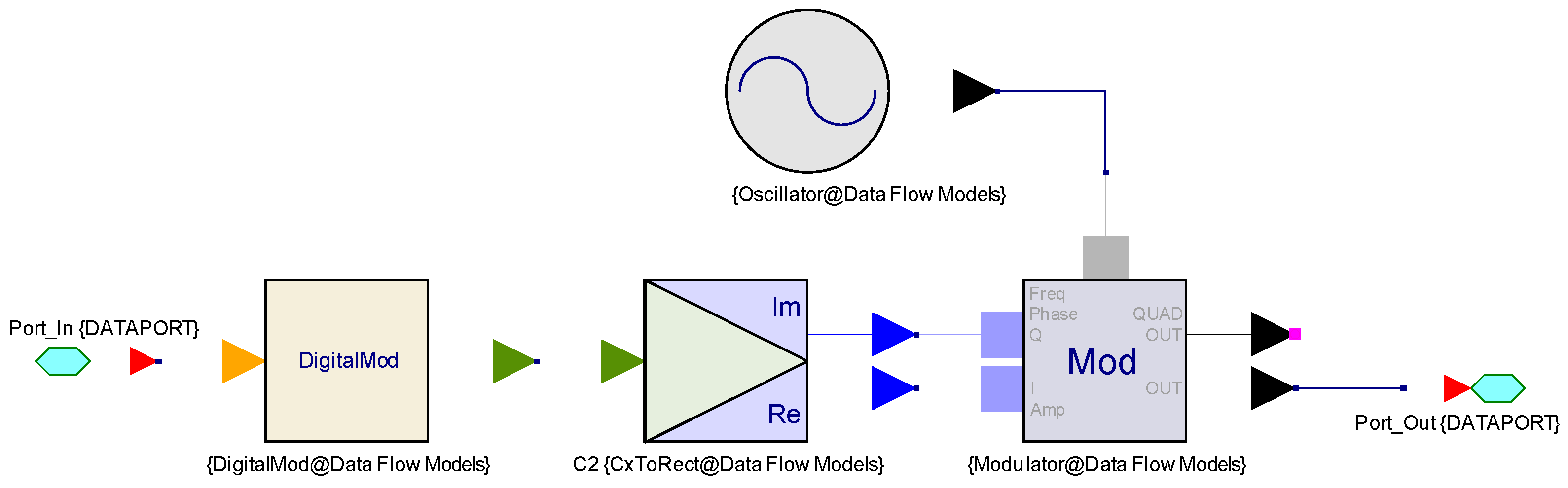
The internal structure of the modulation module is shown in
Figure 3. The modulation includes baseband modulation and radio frequency modulation (IQ modulation), which are implemented by Digital-Mod and Mod components, respectively. Baseband modulation can be interpreted as “zero frequency modulation”, and it is used to modulate the first input signal into digital baseband signals and to carry out oversampling and shaping filtering. The research in [
32] was mainly based on the baseband spatial modulation and demodulation to validate the average bit error rate (BER) performance of the spatial modulation and spatial multiplexing modulation systems. The focus of [
33] mainly lies on the hierarchical quadrature amplitude modulation to accomplish unequal error protection and enhance the received image quality and the results are intent to show the effect of the baseband modulation parameters on the performance of the proposed system. These two paper mainly focused on the baseband modulation and framing of MIMO Orthogonal Frequency Division Multiplexing (OFDM) system while the content of this paper is to dig into the system-level simulation to analyze the influence of the Single Pole Double Throw (SPDT) on the MIMO system performance. Therefore, considering the length of the paper, the baseband processing of the MIMO system is simplified and briefly discussed.
Among them, oversampling is beneficial to improve the signal-to-noise ratio and reduce the BER. Shaping filter is mainly used to eliminate inter-symbol interference. It can be divided into rectangular filter, raised cosine filter, square root raised cosine filter, and Gauss filter. The difference between four kinds of filters depends on steep degree of the window function in rising and falling edges, which is closest to the ideal rectangular filter. But in practice, the raised cosine filter is commonly used for its low cost. The tail attenuation process is much quicker than the Nyquist filter (sinc function) and greatly reduces the inter symbol interference, with roll off factor of 0.35.
The digital baseband signal is converted in digital analog converter after IQ modulation. The Mod can choose different modulation modes: amplitude and frequency modulation, amplitude and phase modulation and IQ modulation. In this system, IQ modulation is selected and the two signals are orthogonal to each other, with only a 90° difference in phase. They are transmitted with the same carrier frequency to effectively improve the spectrum utilization. An internal local oscillator signal is loaded on the component to move the real signal information to the specified frequency and sets it directly to the system’s intermediate frequency of 220 MHz.
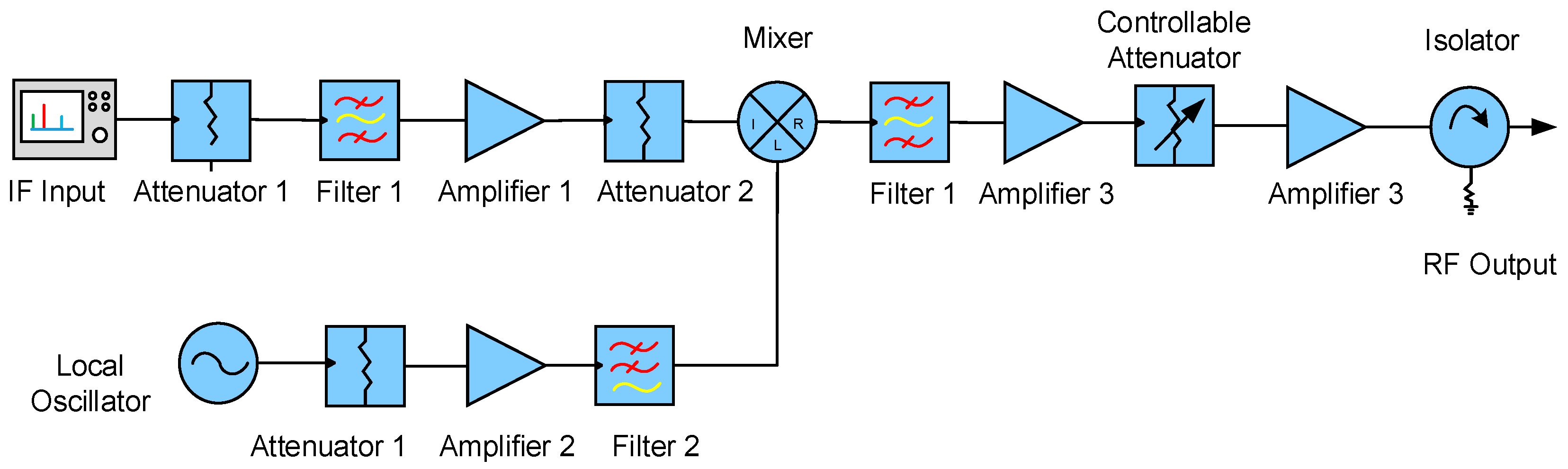
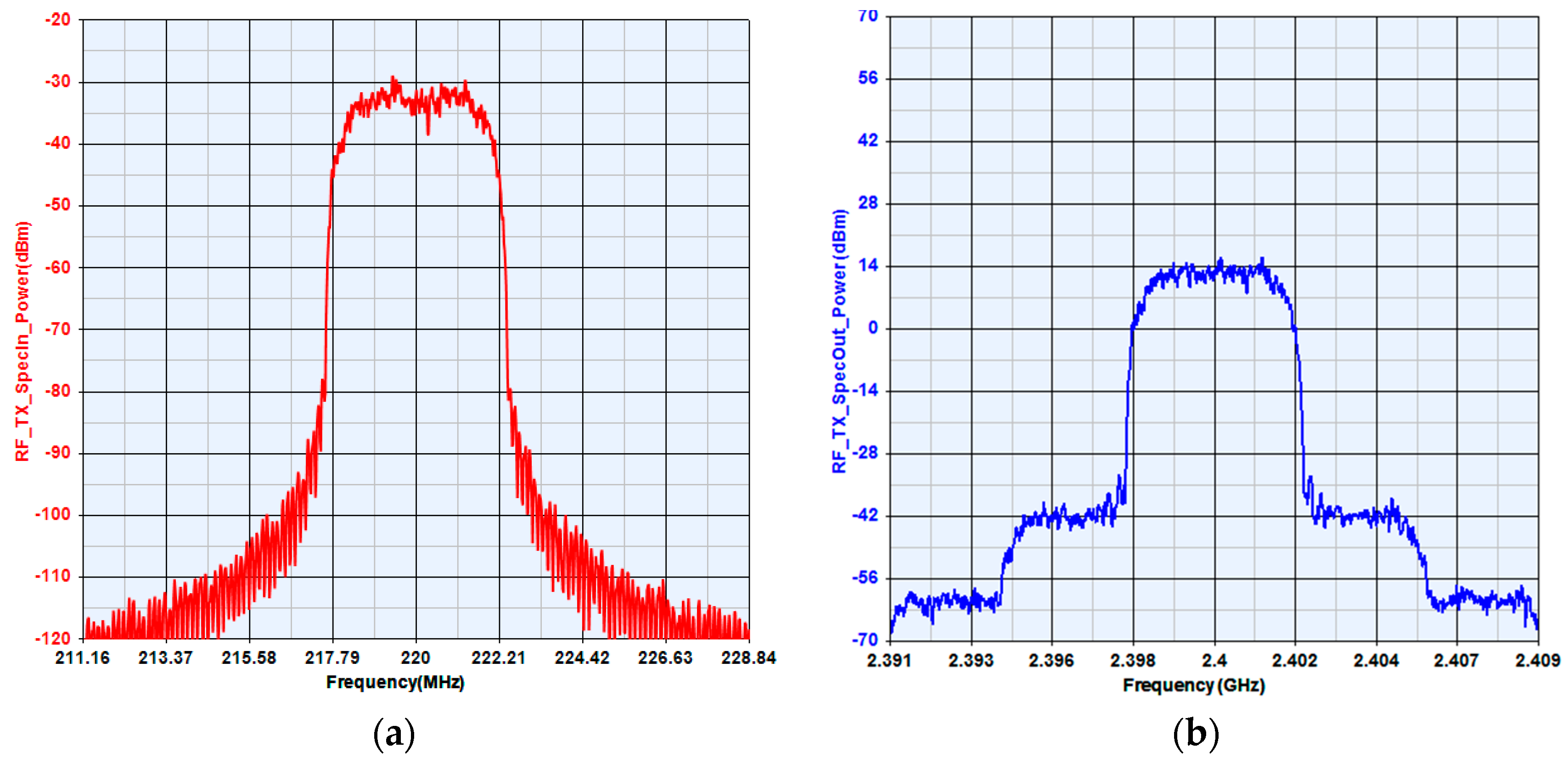
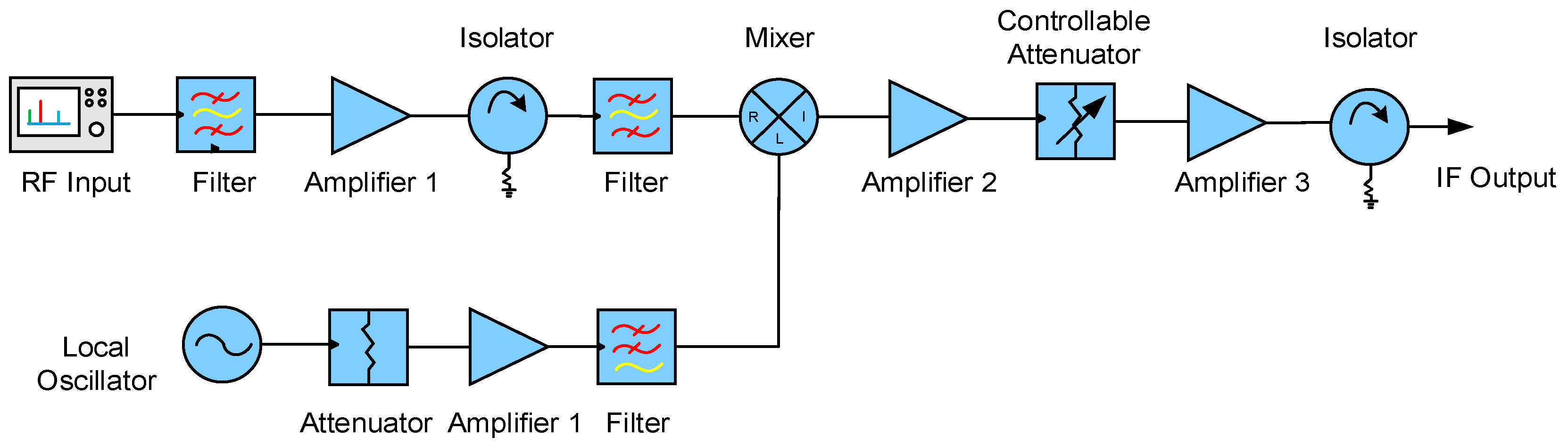
The IQ modulated signal is the intermediate frequency analog signal. In order to improve the accuracy of this signal, it is necessary to load the signal to the high frequency signal. The schematic diagram of the RF transmitter module is shown in
Figure 4.
This module mainly realizes the signal conversion process. The modulated signal passes through the attenuator, Chebyshev band-pass filter, amplifier, and nonlinear adjustable attenuator to the signal source input mixer. The Chebyshev band pass filter is close to the IQ modulator to suppress off band stray signals at the transmitter, and the controllable attenuator is used to control the power gain of the RF link. The oscillator of the mixer is supplied directly by an oscillator with a resonant frequency of 2180 MHz, and the oscillator output signal will pass through an attenuator, an amplifier and a Butterworth low-pass filter in turn. The signal is transmitted through an antenna after a Butterworth bandpass filter, a multistage RF amplifier and an isolator.
The specific parameters of each component at the RF transmitter module are listed in
Table 2. The input and output impedances of all components are default to 50 ohms.
Figure 5 compares the input and output spectrum of the RF transmitter, with input center frequency of 220 MHz and the peak power of −32 dBm. The output center frequency is 2400 MHz, with peak power of 14 dBm. The RF link at the transmitter can effectively realize the up-conversion process and the output power of each component agrees with the parameters set up previously.
3.2. Receiver Modeling
In order to verify the accuracy and effectiveness of SystemVue simulation platform and test other characteristics of the MIMO system, a more mature super-heterodyne receiver is proposed. Super-heterodyne receiver uses uniform linear array antenna as a receiving antenna to recover two binary digital signal by converting the two received signals with a certain algorithm. Comparing the binary digital signal with the input signals, the system symbol error rate will be acquired.
The internal structure of the receiver module is shown in
Figure 6. The core component of the RF module is the mixer for down conversion. In order to make the best performance of the mixer, the filter, amplifier and isolator are added to the input signal to make the waveform more stable and smooth, and to reduce the interference of vibration signal at the antenna end as much as possible. With tunable attenuator, amplifier and filter after the local oscillator, it is convenient for subsequent demodulation and decoding.
The specific parameters of each component at the RF transmitter module are listed in
Table 3. The receiver RF module uses the elliptic band-pass filter to filter the received RF signal clutter. Other element parameters that are not mentioned in
Table 3 are the same as the transmitter module.
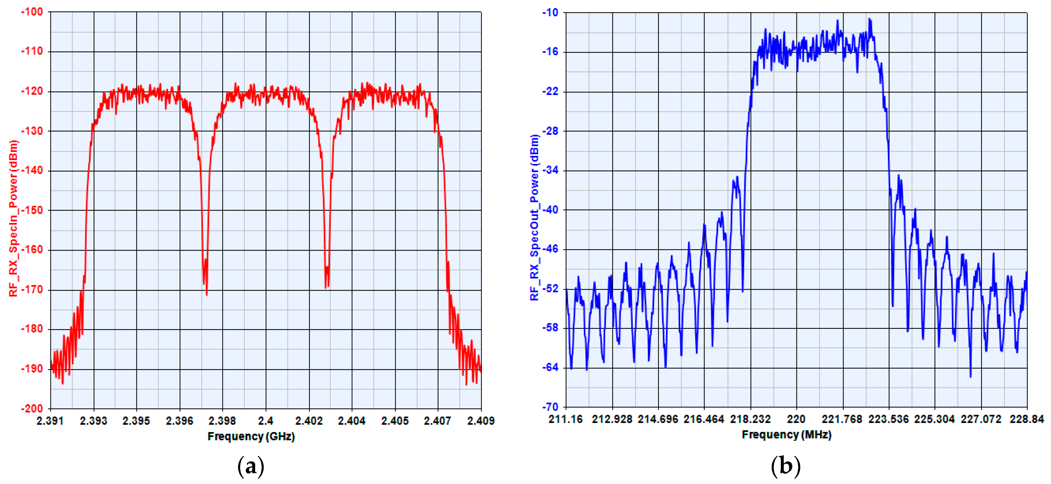
In the actual situation, the signal may be interfered by mixed clutter, resulting in multiple input signal of continuous wave in the spectrum. For example, signals with center frequency of 2400 MHz might produce 2395 MHz and 2405 MHz components due to the channel spacing and there may also exist image signal with center frequency of 2180 MHz in the super-heterodyne receiver.
In order to ensure that the receiving end will not affect the operation of the whole system, the input and output spectrum of the RF link should be measured, as is shown in
Figure 7. The result compares input and output spectrum of RF receiver, with an input center frequency of 2400 MHz and a peak power of −120 dBm. The center frequency of the output IF signal is 220 MHz, with a peak power of −13 dBm, which increased 107 dBm compared with the input terminal. It proves that the RF link receiver effectively realized the conversion process and the output power matches with the parameters set up previously.
3.3. Flow of the Simulation
The whole system is built from the simple to the complex, from the local to the whole. The overall construction and operation process is as follows:
- (1)
The single link can realize the modulation and demodulation process, which is not related to the RF link, channel or noise. The first signal by IQ modulation in transmitter directly passed the SPDT switch. In the ideal state, if the measured bit error rate is 0, the demodulated signal constellation distribution will be concentrated in [−1,0] and [1,0], which means the correctness of the system design.
- (2)
Design the transmitter and the receiver separately to get the radio link budget. Then measure the RF link power and the input and output spectrum distribution in all nodes to ensure the RF link design is correct. It can be added as a separate module to the MIMO system for further investigation.
- (3)
The transmitting end and the receiving end RF link design need to be incorporated into the system in (1), which will introduce the synchronization module. The feedback time measured by the CorrDelay component gives the BER of the system in the software.
- (4)
On the basis of (3), the channel and Gauss white noise are added to construct the single RF link 2 × 2 MIMO system based on a switched parasitic antenna. Using the parameter scanning function in SystemVue, we can measure the change of system BER with the signal to noise ratio and the channel capacity, which includes the characteristics of single pole double throw switches, switching speed, isolation and insertion loss, system delay, and different encoding modes at the receiver.
4. Results
This section describes the results of the single RF link MIMO system. The main performance of the system that needs to be considered include the system error rate, channel capacity, the dispersion degree of the demodulated signal normalized constellation and the maximum communication rate that the system can reach.
4.1. Influence of the Switch
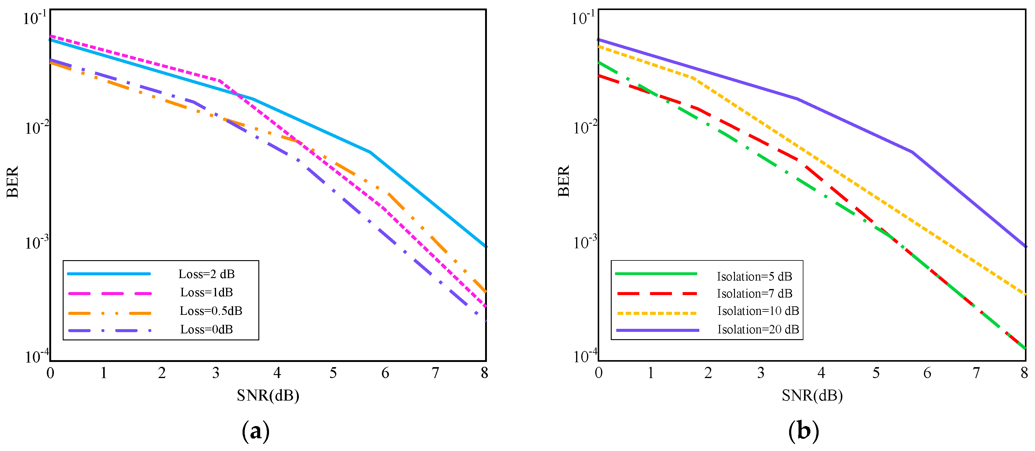
The influence of the SPDT on the system error rate mainly reflects in two variables, including loss and isolation. Considering the actual rate of input symbols and the switching rate of varactor diodes loaded on the switched parasitic antennas, the input symbol speed should be set to 100 KHz in simulation. The switching time is in the ns level and the system error rate range is small, which is particularly significant when the BER is less than 8 dB.
Figure 8a describes the impact of the SPDT switch loss on the bit error rate of the system. It is not difficult to find that the system bit error rate increases with switching loss. It will be more obvious when the signal-to-noise ratio is higher than 2 dB.
Figure 8b shows that with the decrease of the SPDT switches isolation, the system bit error rate will also increase. Generally, when the system error rate reaches 10
−2 or lower, it is usually possible to determine the communication system ability to accurately transmit the information.
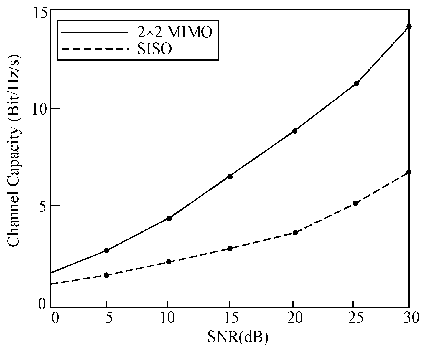
Before investigating other characters of the MIMO system, the switching time of SPDT switch is set to 1 ns according to the above simulation results. The loss and the isolation degree are set to 1 dB and 10 dB, respectively. Based on this, the transmitter and the channel should be separately simulated to get the channel matrix. The real part and the imaginary part are imported into the two txt. files, then use the Channel_Capacity element to determine the system channel capacity at the stable state, as is shown in
Figure 9. The solid line represents the channel capacity of the 2 × 2 MIMO system and the dotted line compares the channel capacity of the single input single output (SISO) systems. It is not difficult to find that the capacity of the 2 × 2 MIMO system is nearly twice that of the SISO system.
4.2. Spectrum Characteristics
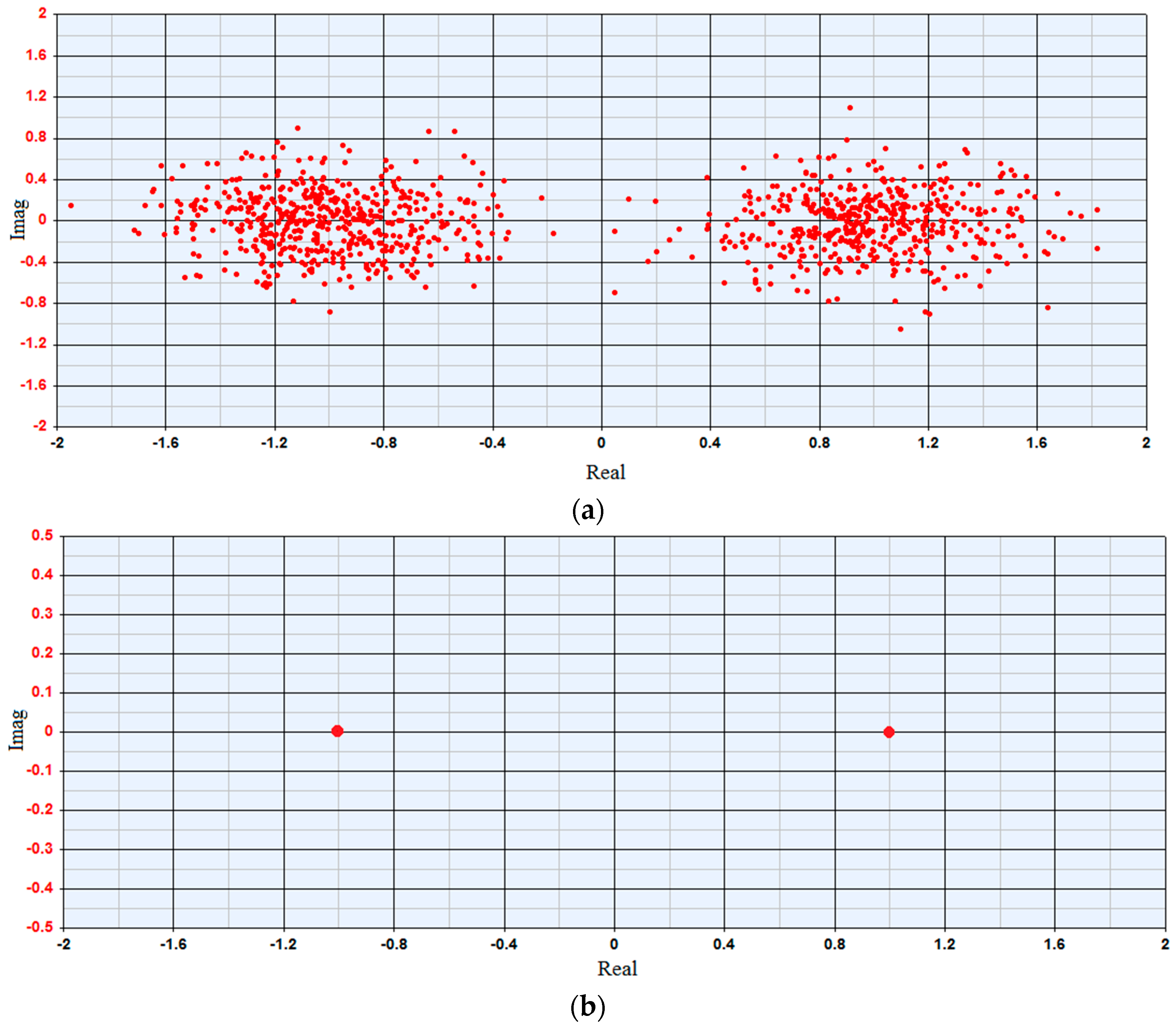
In addition to the main standard of the above system, the demodulated signal constellation is shown in
Figure 10. For an ideal communication system without any noise or interference factors, the demodulated constellation should be fixed at [1, 0] and [−1, 0], as is shown in
Figure 10b. However, in
Figure 10a, the demodulation constellation points are uniformly scattered around [1, 0] and [−1, 0], which can be explained by the additive Gauss white noise, non-idealization of antennas and other components in the system.
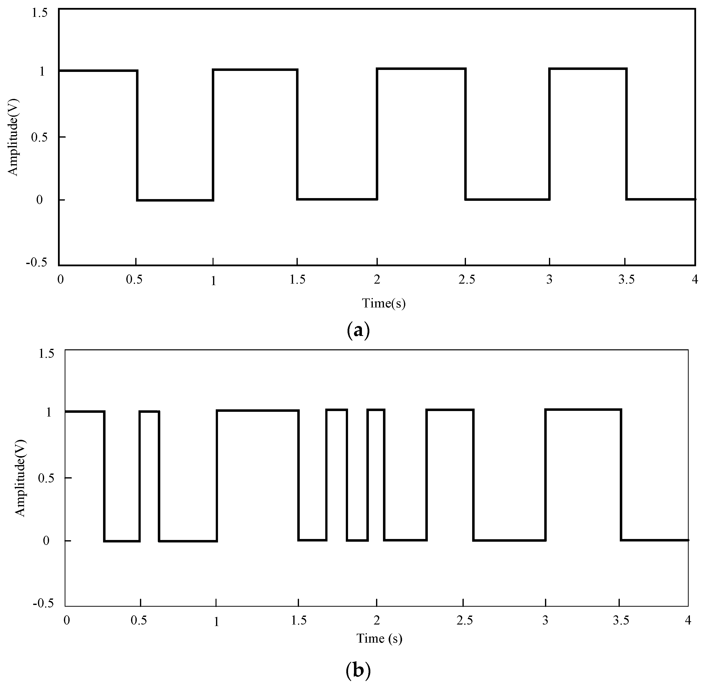
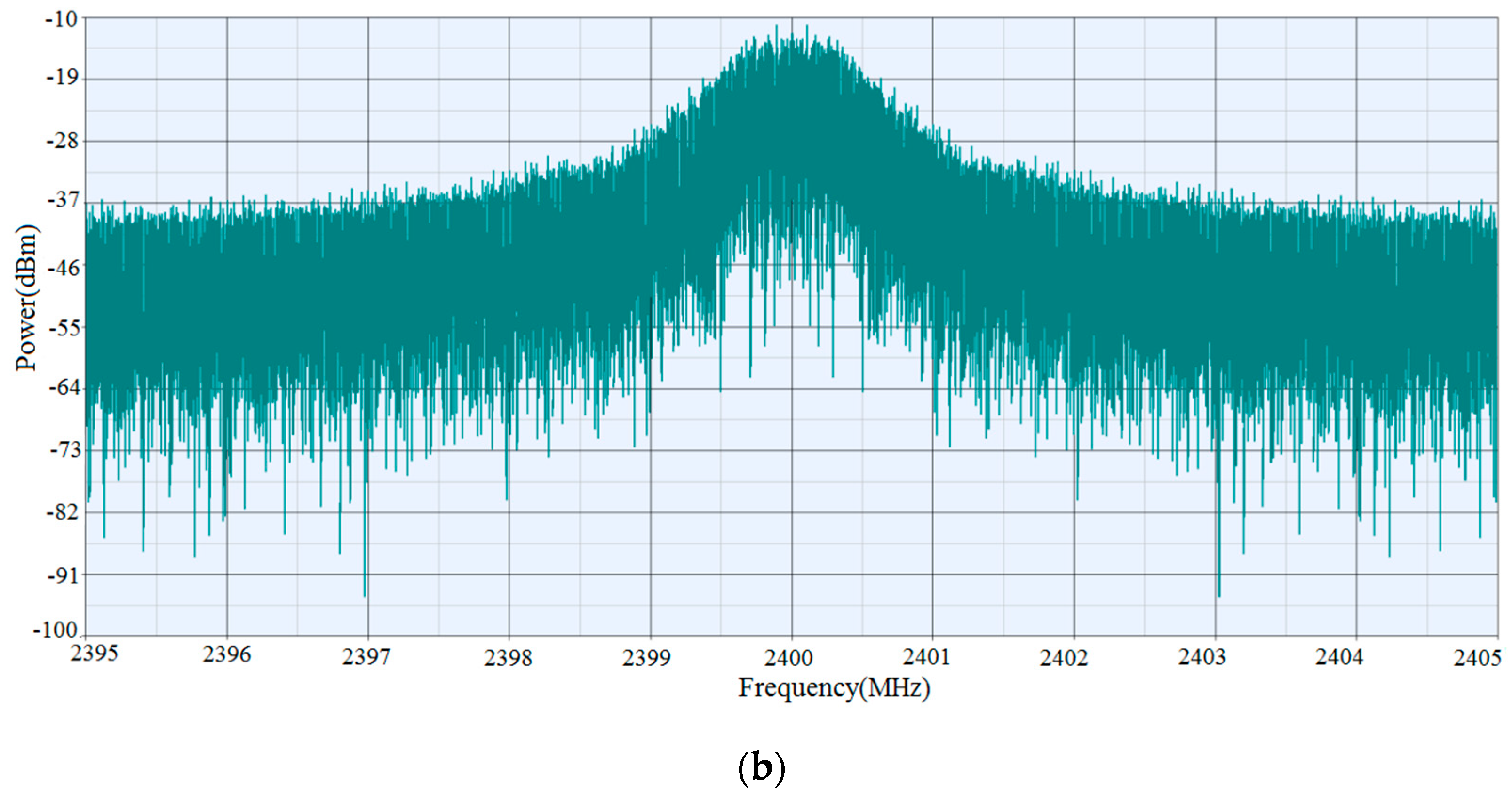
The spectrum broadening problem caused by switching is verified by the following method. The stronger the randomness of input signal, the greater the degree of spectrum broadening. In order to ensure the first input signal is the fixed symbol pattern, we only change the second input symbols: one is the symbol with the fixed form, the other is the pseudo-random code. The states of the two input signals in the time domain are shown in
Figure 11a,b, respectively.
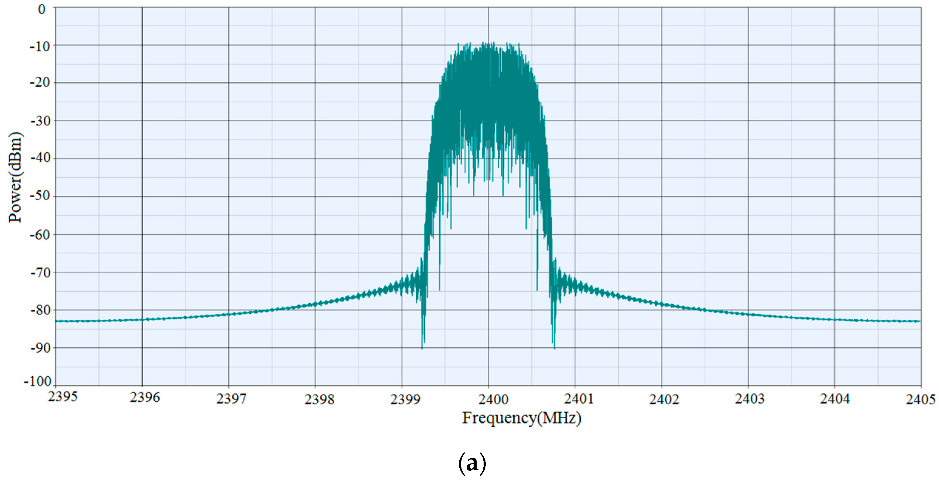
The two input signals are used as the second input symbols of the system, and the spectrum of the output of the SPDT switch is measured, as is shown in
Figure 12.
When the second input symbols and the first input symbols are completely the same, the XOR results will be zero and there are only one far field radiation pattern with the help of spectrum shaping filter. At the 2.4 GHz center frequency, there is only one peak and the spectrum components are clean. When the second input symbols are converted into the random symbols, the XOR results of the two signals are random variable, which results in the change in the antenna far-field radiation pattern. Besides, the spectrum will also show obvious band clutters, which produces the spectral broadening. In addition, when the switched parasitic antenna switches the state, the peak value of the power in the spectrum will also decrease from −10 dBm to −14 dBm.
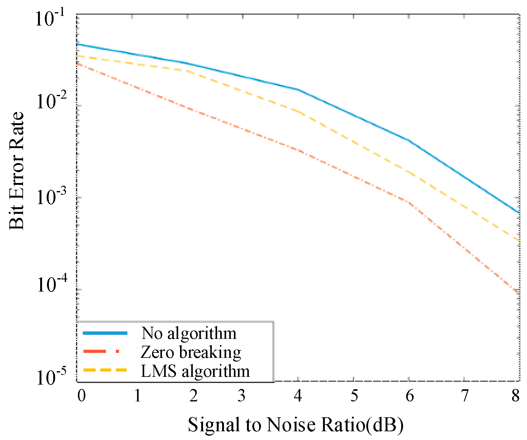
4.3. Influence of Receiver Coding Mode
In order to eliminate the influence of other interferences except for Gauss white noise in the system, the zero forcing algorithm and the least mean square error algorithm are introduced into the module to recover the signal at the receiver. The system error rate variation regularity with the signal to noise ratio is shown in
Figure 13.
As can be seen from the curves, the system error rate is reduced by the zero forcing algorithm or the least mean square error algorithm, and the latter algorithm is even better. This is because the zero forcing algorithm will eliminate other interference factors except the additive Gauss white noise in the system, and the least mean square error algorithm takes the noise into consideration. Although the minimum mean square error algorithm can greatly reduce the system error rate, the algorithm complexity is higher, resulting in long operation time in the system. The BER results under the influence of the SPDT in
Figure 8 are much lower compared with the results in [
34] especially when the SNR is ranged from 0 dB to 5dB. As for the high SNR, the comparison between the two methods remains robust. Take the BER results at 0dB for an example, compared with the single RF MIMO with Electronically Steerable Parasitic Array Radiators under ideal or non-ideal situation, the system structure proposed in our paper is lower than 0.1, while the single RF MIMO system with Electronically Steerable Parasitic Array Radiators is higher than 0.1, which verifies the effectiveness and superior performance of the proposed system.


