1. Introduction
As of the end of 2024, eight major cities including Shanghai, Beijing, and Hangzhou have each achieved operational urban rail transit mileage exceeding 500 km. Shanghai has the longest mileage at 896 km. The total nationwide operational urban rail transit mileage now surpasses 12,000 km. Metro systems dominate urban rail transit and have undeniably become one of the most critical transportation modes in Chinese cities. In recent years, accidental surface surcharges near metro shield tunnels have frequently occurred. These events have led to adverse effects, such as bolt fractures, segment cracking, and localized water leakage in shield tunnels. This compromises the safety of metro operations. Consequently, research on the impact of accidental surface surcharges on underlying shield tunnels is of significant importance.
Numerous domestic and international scholars have conducted research on the impact of accidental surface surcharges on underlying shield tunnels. These studies can be categorized into four primary methodologies: theoretical calculations [
1,
2,
3,
4,
5], field measurements [
6,
7,
8,
9,
10], finite element simulations [
11,
12,
13,
14,
15,
16,
17,
18], and model testing [
19,
20,
21,
22,
23]. Among these approaches, model testing offers advantages of lower costs and reliable results. Liu Xian et al. [
19] investigated the failure mechanisms of double-circle shield tunnels through model testing. Their experiments revealed that the failure process under surcharge loading progresses through three stages, namely, the initial linear behavior, rapid accumulation of plastic damage, and overall instability. Zhang Yanming et al. [
20] conducted model testing to examine the influence of surcharge loads on shield tunnels in strata with varying proportions of hard rock. They found that the proportion of hard rock in the surrounding stratum significantly affects tunnel displacement and deformation under accidental surcharge. Higher hard-rock proportions correspond to greater critical failure loads. Liang Rongzhu et al. [
21] fabricated a refined shield tunnel model using 3D printing technology and employed model testing to investigate stress-deformation mechanisms under accidental surcharge. Wei et al. [
22] conducted a 1:15.5 geometrically scaled indoor model test, systematically analyzing factors such as surcharge magnitude, tunnel burial depth, load position, and soil properties. This approach enabled them to study tunnel convergence deformation, settlement, and deep soil displacement induced by surface surcharges. Huang Dawei et al. [
23] performed a 1:10 scaled model test to explore deformation mechanisms and soil–tunnel interaction relationships in soft-soil shield tunnels subjected to accidental surcharges. Current research on destructive testing of model shield tunnels remains limited. Existing studies primarily focus on intact segments, yet they overlook potential pre-existing damage from construction or operational phases. However, such pre-damaged segments exhibit significantly higher vulnerability to failure under accidental surcharges. Among various damage forms, cracks represent one of the most common initial defects in shield tunnel segments. This highlights the necessity to investigate failure patterns of shield tunnel segments with pre-existing cracks under accidental surcharge conditions through model testing.
This study employed a 1:8 scaled model testing approach, incorporating variables such as initial crack length, quantity, morphology, and surcharge position. By experimentally investigating failure mechanisms of cracked shield tunnel segments under surcharge loading, it generates reference data critical for assessing potential failure modes in tunnels with diverse crack configurations subjected to accidental surface loads. There are many engineering symmetry and asymmetry phenomena in this study.
2. Indoor Model Testing
2.1. Test Overview
The model shield tunnel ring utilized in this study was scaled at 1:8 relative to the typical dimensions of Hangzhou Metro shield tunnels. Specific parameters of the model are detailed in
Table 1. The prototype shield tunnel segments for Hangzhou Metro are constructed with C50-grade concrete.
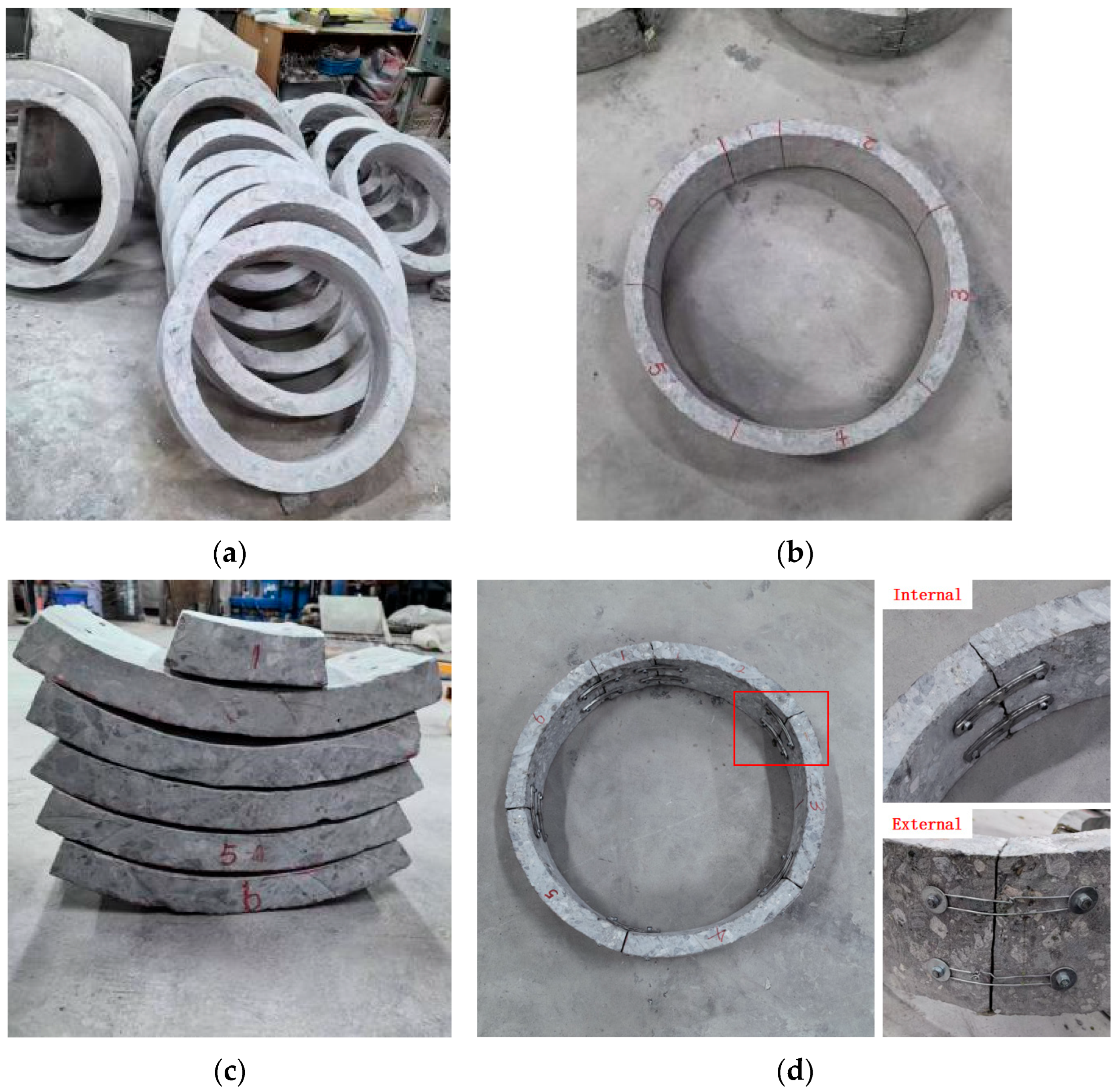
To ensure the mechanical behavior of the model closely approximates that of the prototype, the model was fabricated through four sequential steps, encompassing cutting, thickness grinding, slicing, and assembly. The fabrication process employed Grade II D700 reinforced concrete drainage pipes. A simplified connection method was adopted to focus on self-failure mechanisms of shield tunnel segments with initial cracks under surcharge loading, rather than replicating the prototype’s exact configuration. During assembly, two 127 mm arc-shaped steel angle codes were bolted to the inner surface of the segments for vertical fixation, while steel wire binding secured the outer surface. The resulting model tunnel ring exhibited a reinforcement ratio of approximately 0.3% and a concrete strength grade of C30. The fabrication process is illustrated in
Figure 1.
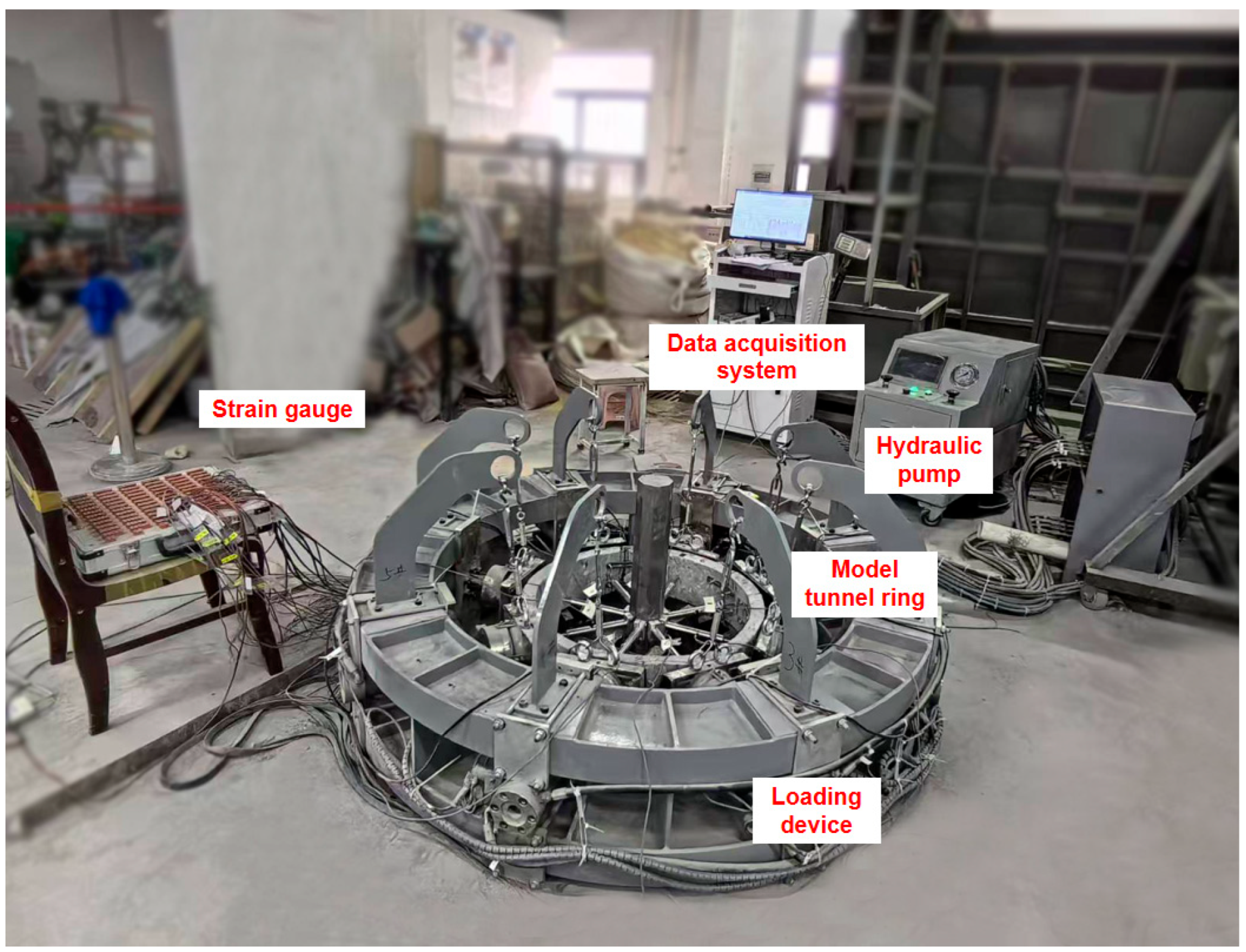
The testing equipment consisted of a loading device, hydraulic pump, resistance strain gauge, and data acquisition system. The loading device incorporated eight loading ports, which were evenly distributed along the model tunnel ring.
Figure 2 and
Figure 3 depict the experimental setup and equipment, respectively.
2.2. Test Conditions
This study investigated the effects of four key factors, i.e., initial crack length, quantity, morphology, and surcharge position, on damaged shield tunnel segments. A total of 10 failure tests were conducted on shield tunnel segments with pre-existing cracks under surcharge loading. For unilateral eccentric loading, the first loading port was applied to segment 6. For bilateral eccentric loading, the first and third loading ports were simultaneously activated, targeting segments 6 and 2, respectively. Eight displacement transducers were evenly distributed inside the tunnel ring to monitor internal displacements during testing. Pressure sensors integrated into the loading ports captured load data. The failure criterion for the model shield tunnel ring was defined as the formation of through-cracks in segments, following the provisions of the technical code for protection structures of urban rail transit (CJJ/T 202-2013) [
24]. In practical engineering, surcharge-induced segment displacements can be easily measured; therefore, each loading increment was controlled by advancing the loading port by 0.5 mm. Detailed test conditions are presented in
Table 2.
2.3. Test Procedures
(1) Model Tunnel Ring Fabrication: Model tunnel rings were fabricated according to test specifications. Initial cracks with predefined depths, lengths, and positions were pre-cut into segments based on the designated test conditions.
(2) Pre-Test Preparation: The model tunnel ring was placed into the loading device, and its position was adjusted to align with test specifications. Eight displacement transducers were evenly installed inside the tunnel ring at locations corresponding to the loading ports. Both the displacement transducers and pressure sensors were linked to the strain gauge for data acquisition.
(3) Tunnel Ring Loading: Loading was executed through specified loading ports as per test conditions, while other ports remained fixed. Prior to formal loading, all eight loading ports were adjusted to ensure tight contact with the model tunnel ring, and an initial load of approximately 0.25 kN was applied to each port. During formal loading, the designated loading ports advanced at a rate of 0.005 mm/s for each 0.5 mm increment. After each increment, a 10 min hold period was implemented. Loading concluded after three additional increments following the formation of through-cracks in any segment.
(4) Data Acquisition: Displacement and pressure data were automatically captured at 1 s intervals throughout the entire test duration.
3. Failure Analysis of Shield Tunnel Segments with Initial Cracks Under Surcharge Loading
In the tests, through-cracks occurred in segment 6 of the model tunnel ring across all test conditions (1–10). This study therefore focused on the analysis of load variations applied by loading port 1 to segment 6 under different conditions. Due to differences in crack length, quantity, morphology, and surcharge position, the number of loading stages required to induce through-cracks in segment 6 varied among test conditions. Experimental data from seven loading stages, four stages before and three stages after through-crack formation, were selected for analysis, as through-cracks appeared at Stage 4.
3.1. Failure Analysis of Intact Segments Under Surcharge Loading
To explore mechanical behavior differences in intact segments across tunnel ring configurations, Test Conditions 1 and 10 were selected for comparative analysis.
Figure 4 illustrates the load variations before and after the failure of intact segment 6 in different tunnel ring configurations.
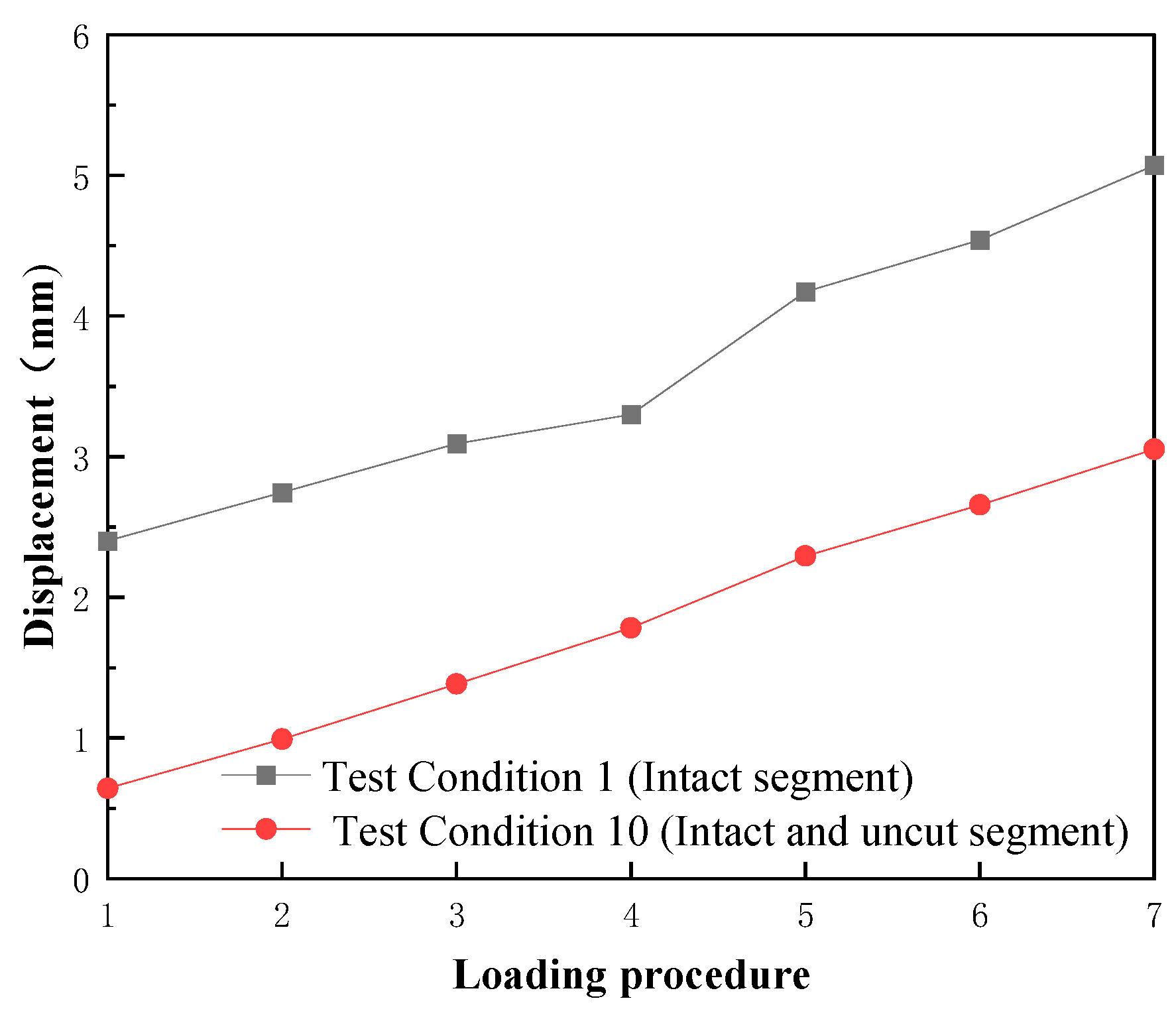
Figure 5 presents the internal displacement variations of intact segment 6 before and after failure under these configurations.
(1) In Test Condition 1, the intact segment 6 within the assembled tunnel ring required a load of 5.27 kN to induce through-cracks, accompanied by an internal displacement of 3.30 mm. By contrast, Test Condition 10 (monolithic tunnel ring without slicing) required a higher load of 6.52 kN (123.7% of Condition 1) and exhibited a lower internal displacement of 1.78 mm (53.9% of Condition 1). This indicates that the monolithic tunnel ring exhibits marginally superior load-bearing capacity, whereas the assembled ring shows greater deformation tolerance. This discrepancy can be attributed to the assembled ring’s capacity to accommodate limited dislocation damage between segments.
(2) Across the seven loading stages (four before and three after through-crack formation), the external displacements of intact segment 6 remained consistently at 3.0 mm for both configurations. However, internal displacements diverged; to be specific, 2.67 mm for the assembled ring (Condition 1) and 2.41 mm for the monolithic ring (Condition 10). Notably, external displacements exceeded internal displacements by factors of 1.12–1.24.
(3) Immediately after through-crack formation, the load required for subsequent loading stages dropped significantly (4.7–15.6%) for both configurations. Nevertheless, the load demand gradually increased in later stages. This occurred because continued loading further compressed segment 6 despite through-crack formation, and the intact internal reinforcement retained residual load-bearing capacity.
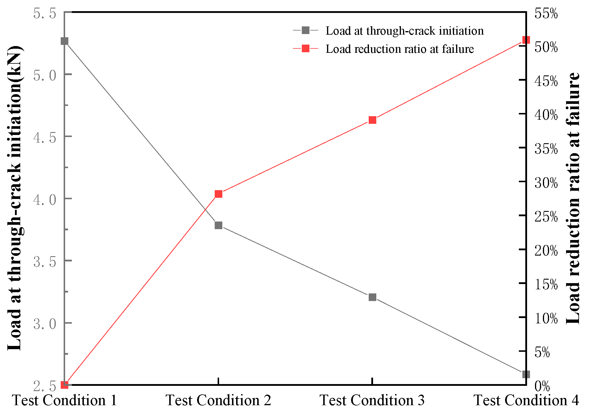
3.2. Effect of Crack Length
To investigate the influence of initial crack length on segment failure under surcharge loading, Test Conditions 1–4 were selected for comparative analysis.
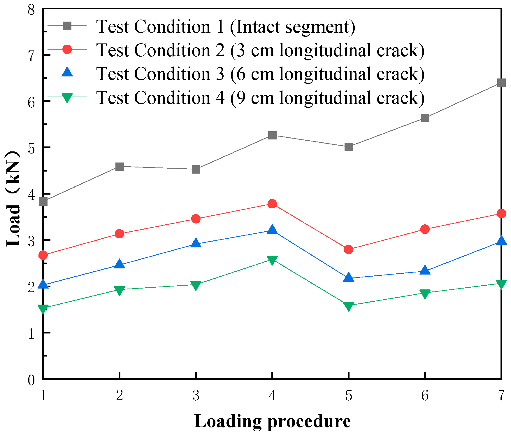
Figure 6 illustrates the load variations before and after failure of segments with different crack lengths, while
Figure 7 presents the failure modes of segments with varying crack lengths.
From
Figure 6 and
Figure 7, in Test Conditions 1–4, the load required for subsequent loading stages after through-crack formation decreased significantly. The maximum reduction (38.6%) occurred in Condition 4. As the initial crack length increased, the critical load required for through-crack formation dropped markedly. Compared to Condition 1 (intact segment), condition 2 showed the most pronounced reduction, while Condition 4 exhibited the largest load reduction (50.9%). These results indicate that the presence of cracks (from no crack to a crack) had a greater impact on load-bearing capacity than incremental increases in crack length.
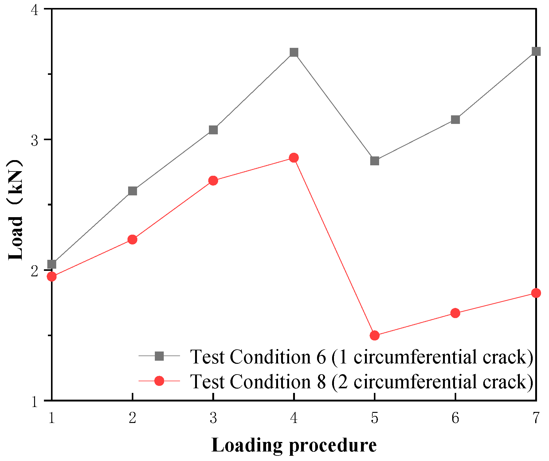
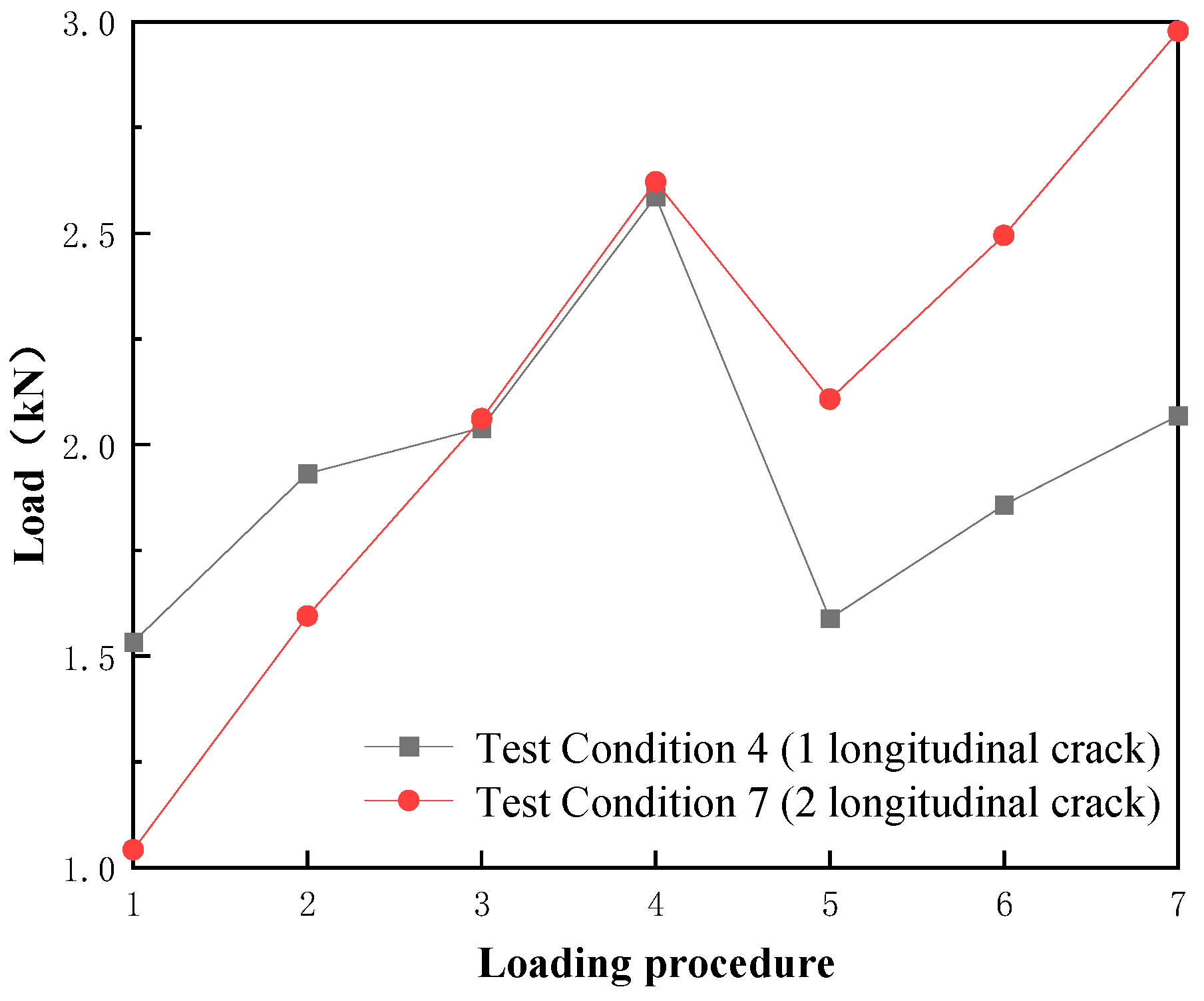
3.3. Effect of Crack Quantity
To investigate the influence of initial crack quantity on segment failure under surcharge loading, Test Conditions 6 and 8, as well as Conditions 4 and 7, were analyzed comparatively.
Figure 8 illustrates the load variations before and after failure of damaged segments in Conditions 6 and 8, while
Figure 9 presents the corresponding data for Conditions 4 and 7.
From
Figure 8, it is evident that as crack quantity increased, the critical load required for through-crack formation dropped significantly. Compared to Condition 6, Condition 8 exhibited a reduction of 0.81 kN (22.1%). Segment displacement increased after through-crack formation when loading continued. The load growth rate in Condition 6 was notably faster than in Condition 8. This likely resulted from concrete crushing in Condition 8’s multiple-crack segments during and after through-crack formation, which substantially reduced load-bearing capacity.
As shown in
Figure 9, despite Condition 7 having two 9 cm longitudinal cracks versus one 9 cm longitudinal crack in Condition 4, the critical loads for through-crack formation were nearly identical (2.62 kN for Condition 7 vs. 2.59 kN for Condition 4). After through-crack formation, the load reduction in Condition 4 was 1.00 kN (38.6%), whereas Condition 7 exhibited a smaller reduction of 0.51 kN (19.5%). This discrepancy arose from differences in crack positions. In Condition 7, the two cracks were located at the one-third and two-thirds positions of the segment; in Condition 4, the single crack aligned with the half-length position, which corresponded to the loading point of Port 1.
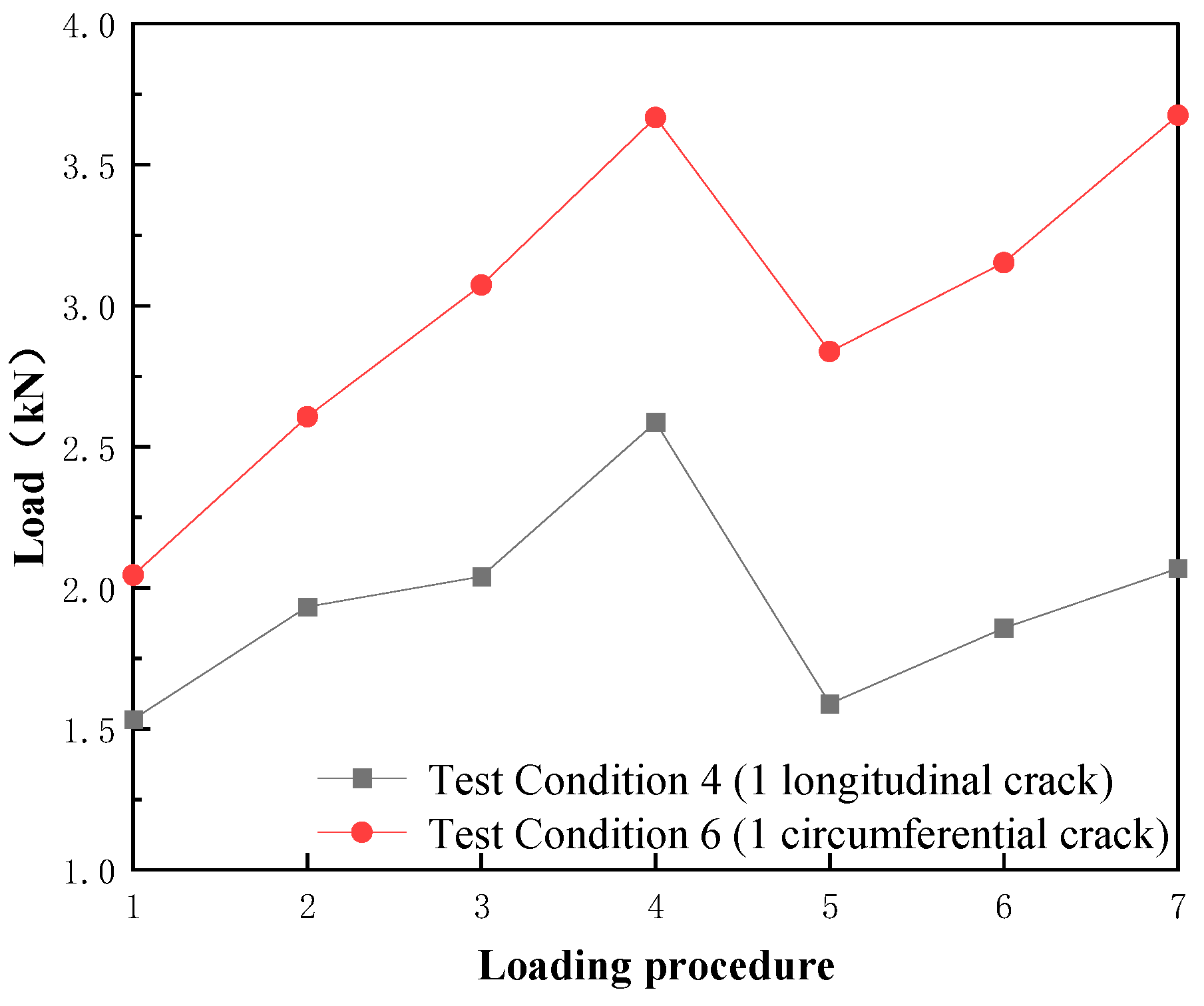
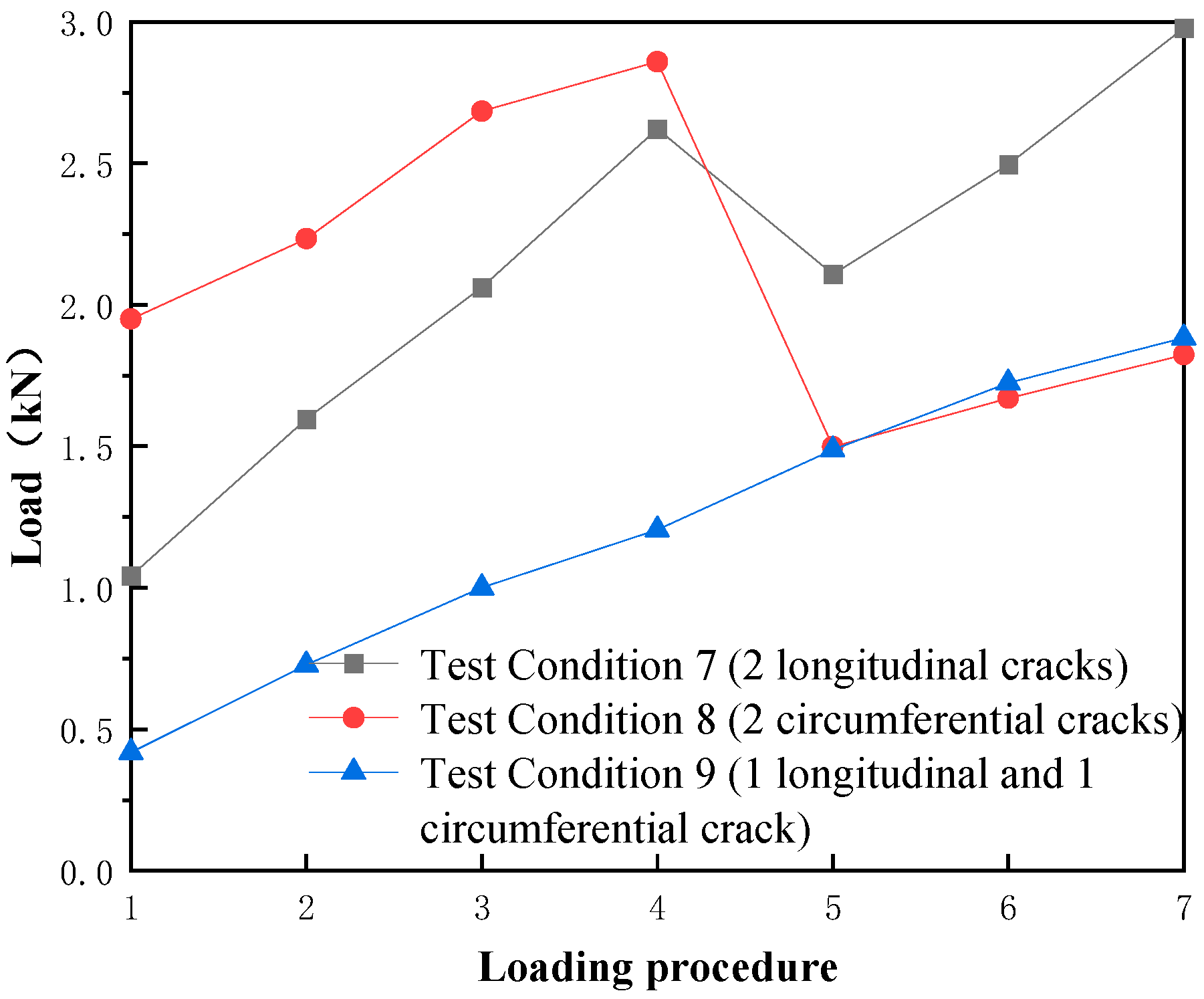
3.4. Effect of Crack Morphology
To investigate the influence of initial crack morphology on segment failure under surcharge loading, Test Conditions 4 and 6, as well as Conditions 7–9, were comparatively analyzed.
Figure 10 displays the load variations before and after failure of damaged segments in Conditions 4 and 6, while
Figure 11 presents the corresponding data for Conditions 7–9.
From
Figure 10, despite identical initial crack lengths and central positions in Conditions 4 (longitudinal crack) and 6 (circumferential crack), the critical loads for through-crack formation differed significantly. Condition 4 required 2.59 kN, whereas Condition 6 required 3.67 kN. The failure load in Condition 4 was only 70.6% of that in Condition 6, indicating that longitudinal cracks pose significantly greater risks compared to circumferential cracks.
(1) Although Condition 7’s two longitudinal cracks were located at the one-third and two-thirds positions (not the center), the critical load for through-crack formation (2.62 kN) remained lower than Condition 8’s 2.86 kN (double circumferential cracks). This confirms that longitudinal cracks are more detrimental than circumferential cracks.
(2) In Condition 9, the segment contained a 9 cm circumferential crack and a 6 cm longitudinal crack. The critical load for through-crack formation was 1.20 kN, only 42.0% of Condition 8’s value. This suggests that staggered longitudinal-circumferential cracks cause far greater damage than double circumferential cracks.
(3) The critical load in Condition 7 (2.62 kN) was 2.18 times that of Condition 9, implying that staggered longitudinal-circumferential cracks are more hazardous than pure longitudinal cracks. However, differences in initial crack positions between these conditions may affect comparability, necessitating further investigation.
(4) No load reduction occurred in Condition 9 after through-crack formation. This may be attributed to rapid load recovery during crack propagation, where minor load reductions were masked by subsequent sharp increases.
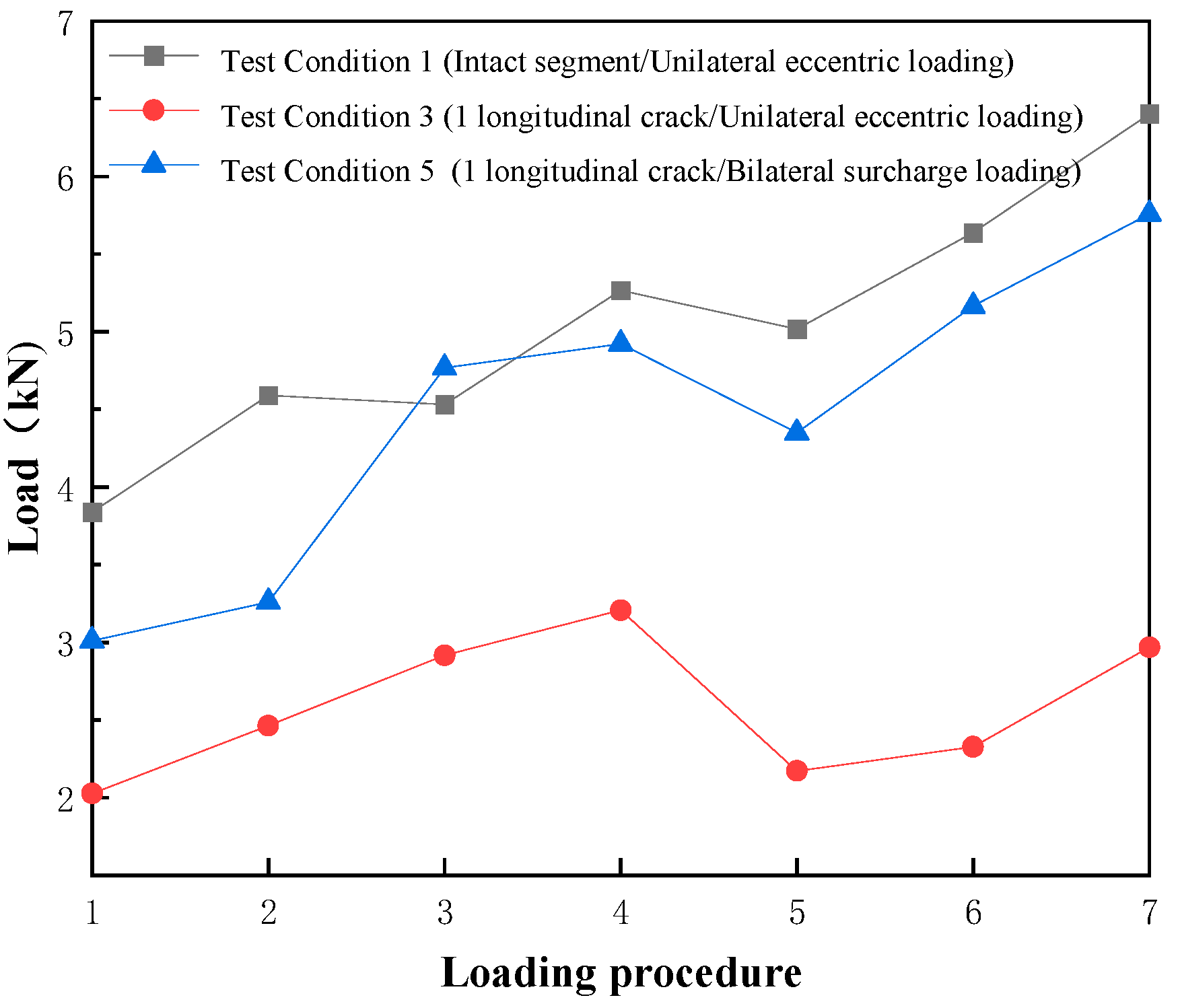
3.5. Effect of Surcharge Position
To evaluate the influence of unilateral versus bilateral surcharge loading on segment failure, Test Conditions 1, 3, and 5 were selected for comparative analysis.
Figure 12 illustrates the load variations before and after failure of segments in these conditions.
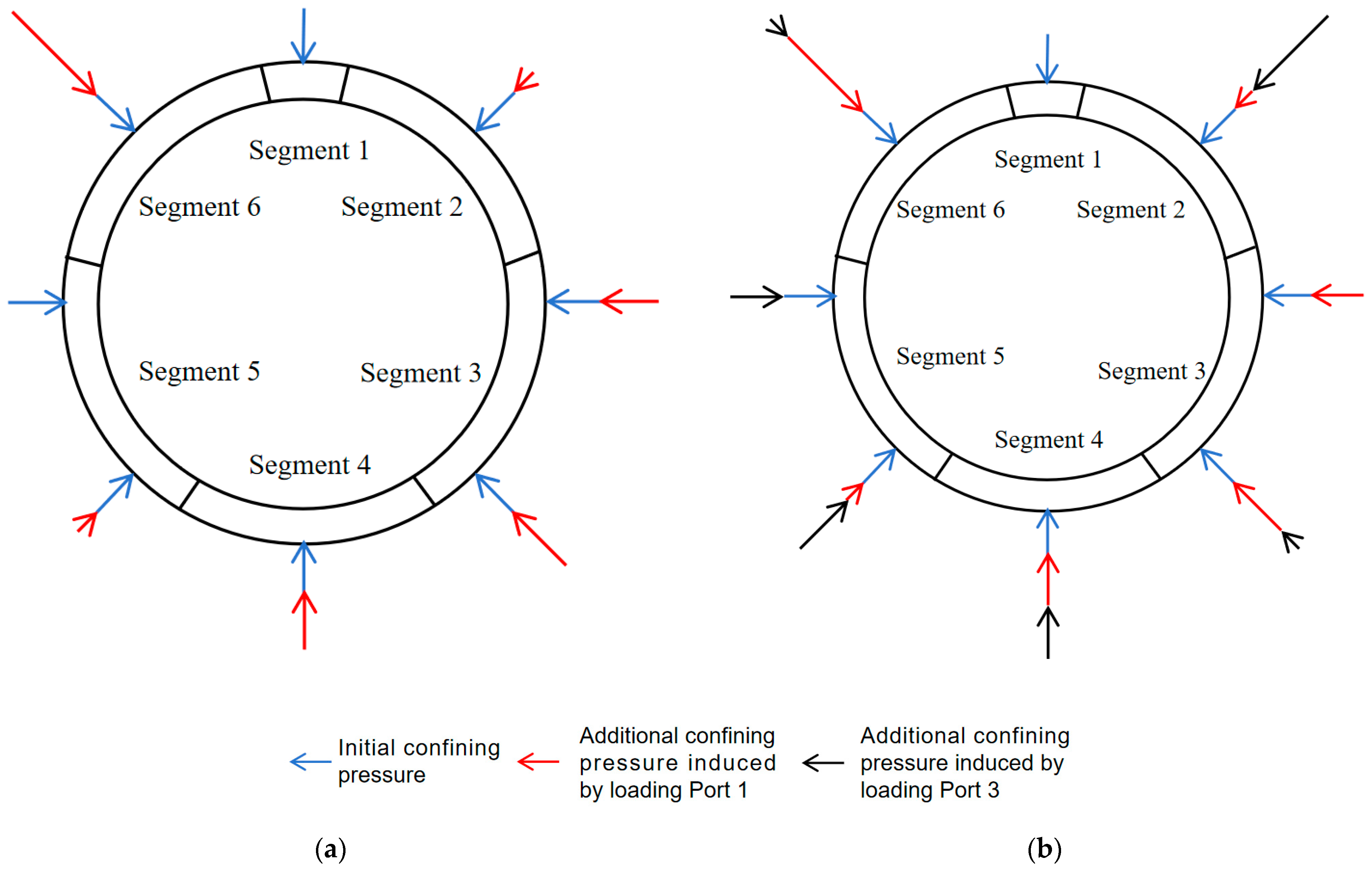
The sole difference between Conditions 3 and 5 lies in the loading configuration. Specifically, Condition 3 applied unilateral loading via Port 1, while Condition 5 implemented bilateral loading through Ports 1 and 3. From
Figure 12, it is evident that the critical loads for through-crack formation were 5.27 kN (Condition 1), 3.21 kN (Condition 3), and 4.92 kN (Condition 5). Notably, Condition 5 required 93.4% of Condition 1’s load and 153.3% of Condition 3’s load. Additionally, bilateral loading significantly increased the critical load compared to unilateral loading. This occurred because bilateral loading (Condition 5) led to a more uniform increase in confining pressure across the tunnel ring, thereby enhancing the load threshold for through-crack formation. Similar phenomena were observed in experimental studies by Guo Wenqi et al. [
25]. The confining pressure distribution differences under unilateral and bilateral loading are shown in
Figure 13.
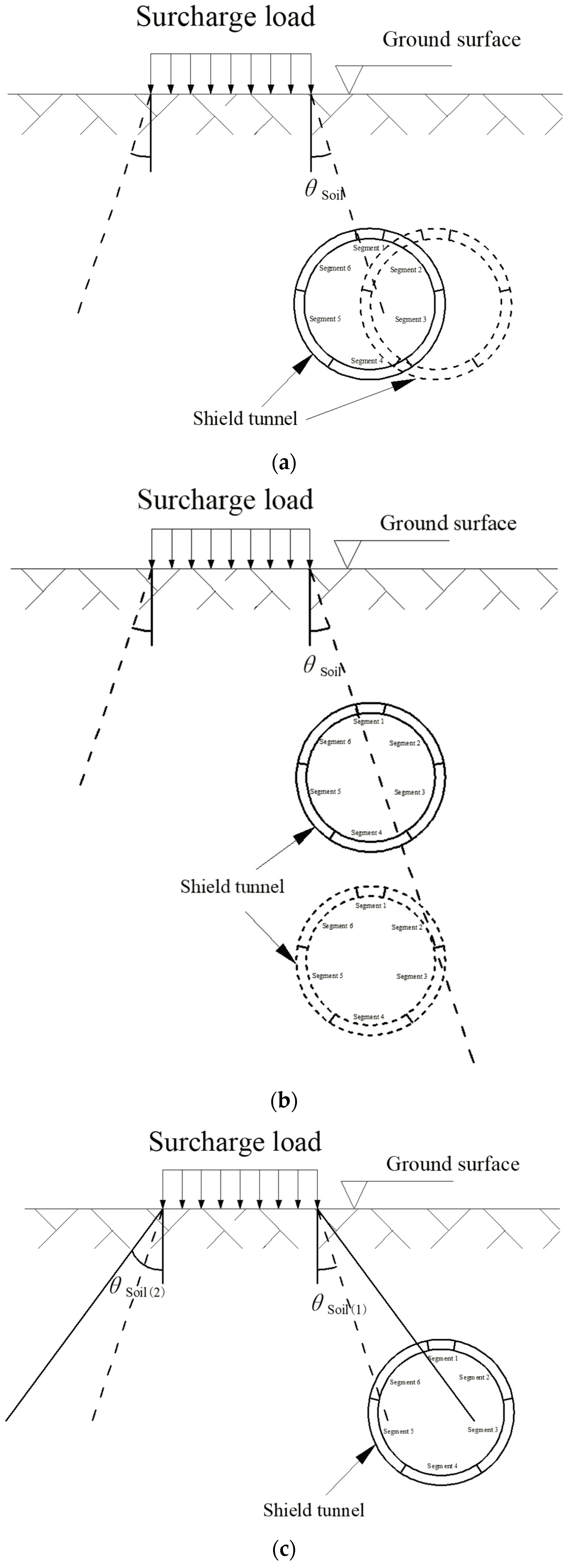
4. Discussion
(1) Variations in the horizontal distance between surcharge and tunnel, tunnel burial depth, and soil pressure diffusion angle (
θsoil) lead to significant differences in the forces acting on shield tunnel segments under accidental surcharge loading. The method employed in this study is particularly applicable when the surcharge force primarily concentrates on segment 6, given specific combinations of these parameters. For different configurations of surcharge–tunnel horizontal distance, burial depth, and
θsoil, the impact of accidental surcharge on underlying shield tunnels was visualized, as shown in
Figure 14.
(2) Initial crack length, quantity, and morphology of shield tunnel segments significantly influence the propagation path of through-cracks under surcharge loading. In Conditions 2, 3, 4, 5, and 9, where segments initially contained longitudinal cracks, through-cracks developed along the orientation of the initial cracks regardless of their length. In Condition 7, two initial longitudinal cracks located at one-third and two-thirds positions of segment 6 (not the center) led to vertical through-crack propagation along one of the initial cracks. In Conditions 6 and 8, where only circumferential cracks existed, through-cracks initiated from the middle of the initial cracks and propagated vertically. Final through-crack patterns for Conditions 1, 2, 6, and 7 are illustrated in
Figure 15.
5. Conclusions
(1) Regardless of the initial damage status, the load required for through-crack formation dropped significantly in the loading stage immediately after crack initiation but gradually increased in subsequent stages. This phenomenon occurred because continued segment compression and intact internal reinforcement after through-crack formation restored partial load-bearing capacity.
(2) Longer initial crack length and higher crack quantities markedly reduced the critical load for through-crack formation. The presence of cracks (from no crack to a crack) had a greater impact on load-bearing capacity than incremental increases in crack length. Initial cracks strongly influenced the propagation path of through-cracks under surcharge loading. Staggered longitudinal-circumferential cracks caused the most severe damage, followed by pure longitudinal cracks, while circumferential cracks exhibited the least detrimental effects.
(3) The critical load for through-crack formation in monolithic (uncut) intact segments exceeded that of assembled segments by 23.7% (123.7% of Condition 1), with internal displacements reduced to 53.9% of the latter. This indicates that monolithic rings exhibit marginally superior load-bearing capacity but significantly lower deformation tolerance compared to assembled rings.
(4) Bilateral loading substantially increased the critical load for through-crack formation by 53.3% compared to unilateral loading. This occurred because bilateral loading induced a more uniform confining pressure distribution across the tunnel ring, thereby enhancing structural resistance. These findings highlight the severe risks posed by uneven confining pressure to shield tunnels.
In the future, the same test method can be used to further simulate the failure law of shield tunnel segments with block falling damage under surcharge loading. However, the current test method hardly simulates the influence of soil conditions on the surcharge failure of shield tunnels.
Author Contributions
Conceptualization, P.X. and H.J.; methodology, P.X., Y.Q. and Y.L.; validation, P.X., G.W. and H.J.; formal analysis, P.X., Y.Q. and Y.L.; resources, G.W.; data curation, P.X., Y.Q. and Y.L.; writing—original draft preparation, P.X.; writing—review and editing, P.X., Y.Q. and Y.L.; supervision, G.W.; project administration, P.X., G.W. and H.J.; funding acquisition, P.X., G.W. and H.J. All authors have read and agreed to the published version of the manuscript.
Funding
This research was funded by the “Tianshan Talent” Youth Top-Notch Talent Cultivation Program, grant number 2024TSYCCX0037; the Zhejiang Provincial Department of Education 2024 Domestic Visiting Engineer Program for University-Enterprise Cooperation Projects, grant number FG2024375; and the National Natural Science Foundation of China, grant numbers 52369021 and 52178399.
Data Availability Statement
The original contributions presented in this study are included in the article. Further inquiries can be directed to the corresponding author.
Conflicts of Interest
The authors declare no conflicts of interest.
References
- Liang, R.Z.; Wang, L.X.; Li, Z.C.; Kang, C.; Gao, K.; Ke, Z.B. Effect of ground surface surcharge on longitudinal deformation of existing shield tunnel. J. Archit. Civ. Eng. 2023, 40, 130–141. [Google Scholar]
- Zhang, Z.G.; Zhang, Y.B.; Zhang, C.P.; Wang, Z.W.; Pan, Y.T. Time-domain solution for soil feedback induced by shield tunneling in viscoelastic strata considering influences of surcharge loading. Chin. J. Geotech. Eng. 2021, 43, 34–42. [Google Scholar]
- Ngoc, A.D.; Daniel, D.; Zhang, Z.X.; Huang, X.; Tai, T.N.; Van, V.P.; Ouahcène, N.R. Study on the behavior of squared and sub-rectangular tunnels using the hyperstatic reaction method. Transp. Geotech. 2020, 22, 100321. [Google Scholar]
- Wei, G.; Qi, Y.J.; Wu, H.J. Calculation of rotation and segment ring dislocation deformation caused by surcharge in shield tunnels. Tunn. Constr. 2019, 39, 1781–1789. [Google Scholar]
- Kentaro, Y.; Andrei, V.L.; Daniel, W.W.; Scott, W.S.; Andrew, A. Stability of dual circular tunnels in cohesive-frictional soil subjected to surcharge loading. Comput. Geotech. 2013, 50, 41–54. [Google Scholar]
- Wang, R.L.; Yuan, Q.; Liang, F.Y.; Wang, L.J. Case study and treatment technology for deformed shield tunnel in soft soils induced by road construction. Chin. J. Geotech. Eng. 2023, 45, 112–121. [Google Scholar]
- Liu, T.J.; Chen, S.W.; Ye, Z.W. Analysis of disease and structural safety of shield tunnel under accidental surface surcharge. J. Railw. Eng. Soc. 2019, 36, 67–73. [Google Scholar]
- Wei, G.; Feng, F.F.; Huang, S.Y.; Xu, T.B.; Zhu, J.X.; Wang, X.; Zhu, C.W. Full-scale loading test for shield tunnel segments: Load-bearing performance and failure patterns of lining structures. Undergr. Space. 2025, 20, 197–217. [Google Scholar] [CrossRef]
- Huang, H.; Zhang, D. Resilience analysis of shield tunnel lining under extreme surcharge: Characterization and field application. Tunn. Undergr. Space Technol. 2016, 51, 301–312. [Google Scholar] [CrossRef]
- Shao, H.; Huang, H.W.; Zhang, D.M.; Wang, R.L. Case study on repair work for excessively deformed shield tunnel under accidental surface surcharge in soft clay. Chin. J. Geotech. Eng. 2016, 38, 1036–1043. [Google Scholar]
- Xu, H.; Li, S.K.; Wu, S.X. Study on deformation law and reinforcement effects of metro shield tunnel segments under loading and unloading. Urban Mass Transit 2025, 28, 175–180. [Google Scholar]
- Wang, L.L.; Ding, S.; Huang, L.; Wang, Y.Z.; Zhao, Y.L.; Zhang, F. Working state of existing tunnel under ground sureharge. Sci. Technol. Eng. 2023, 23, 5764–5769. [Google Scholar]
- Ruan, H.F.; Liang, R.Z.; Kang, C.; Li, Z.C.; Ke, Z.B. Three-dimensional elaborate numerical modelling analysis on the deformation mechanism of metro shield tunnel induced by sudden surface surcharge. Saf. Environ. Eng. 2023, 30, 35–45. [Google Scholar]
- Mishra, S.; Zaid, M.; Rao, K.S.; Gupta, N.K. FEA of urban rock tunnels under impact loading at targeted velocity. Geotech. Geol. Eng. 2022, 40, 1693–1711. [Google Scholar] [CrossRef]
- Wei, G.; Hong, W.Q.; Wei, X.J.; Jiang, J.Q. Deformation law and control limit of shield tunnel cross-section under eccentric surcharge load. J. Cent. South Univ. (Sci. Technol.) 2020, 51, 750–757. [Google Scholar]
- Sun, L.W.; Qin, J.S.; Hong, Y.; Wang, L.Z.; Zhao, C.J.; Qin, X. Shield tunnel segment and circumferential joint performance under surface surcharge. J. Zhejiang Univ. (Eng. Sci.) 2017, 51, 1509–1518. [Google Scholar]
- Katebi, H.; Rezaei, A.H.; Hajialilue-Bonab, M.; Tarifard, A. Assessment the influence of ground stratification, tunnel and surface buildings specifications on shield tunnel lining loads (by FEM). Tunn. Undergr. Space Technol. 2015, 49, 67–78. [Google Scholar] [CrossRef]
- Nunes, M.A.; Meguid, M.A. A study on the effects of overlying soil strata on the stresses developing in a tunnel lining. Tunn. Undergr. Space Technol. 2009, 24, 716–722. [Google Scholar] [CrossRef]
- Liu, X.; Liu, Z.; Li, J.P.; Wang, R.L. Experimental investigations on failure mechanisms of DOT shield tunnel subjected to extreme surface surcharge. Chin. J. Geotech. Eng. 2025, 47, 487–494. [Google Scholar]
- Zhang, Y.M.; Liu, T.J.; Zhu, C.; Xiao, J.X. Model tests on deformation and failure characteristics of shield tunnel in soil-rock composite stratum under surface surcharge. J. Railw. Sci. Eng. 2023, 20, 4277–4287. [Google Scholar]
- Liang, R.Z.; Cao, S.A.; Xiang, L.M.; Kang, C.; Chen, F.J.; Li, Z.C.; Ke, Z.B.; Guo, Y. Experimental investigation on longitudinal mechanical mechanism of shield tunnels subjected to ground surface surcharge. Chin. J. Rock Mech. Eng. 2023, 42, 736–747. [Google Scholar]
- Wei, G.; Zhang, S.M.; Xiang, P.F. Model test study on the influence of ground surcharges on the deformation of shield tunnels. Symmetry 2021, 13, 1565. [Google Scholar] [CrossRef]
- Huang, D.W.; Zhou, S.H.; Feng, Q.S.; Lei, X.Y.; Liu, G. Analysis of interaction between existing shield tunnel and stratum under surface surcharge in soft soil region. J. China Railw. Soc. 2018, 40, 95–102. [Google Scholar]
- CJJ/T 202-2013; Technical Code for Protection Structures of Urban Rail Transit. China Architecture & Building Press: Beijing, China, 2013.
- Guo, W.Q.; Feng, K.; Su, A.; He, C.; Xiao, M.Q. Study on influence of confining pressure on mechanical properties of staggered assembly segment lining structure. China J. Highw. Transp. 2021, 34, 200–210. [Google Scholar]
Figure 1.
Fabrication process of the model tunnel ring. (a) Preliminary cutting. (b) Thickness grinding. (c) Slicing. (d) Assembly.
Figure 1.
Fabrication process of the model tunnel ring. (a) Preliminary cutting. (b) Thickness grinding. (c) Slicing. (d) Assembly.
Figure 2.
Experimental setup. (a) Field photo. (b) Schematic diagram.
Figure 2.
Experimental setup. (a) Field photo. (b) Schematic diagram.
Figure 3.
Testing equipment.
Figure 3.
Testing equipment.
Figure 4.
Load variation before and after failure of intact segment 6 in different tunnel ring configurations.
Figure 4.
Load variation before and after failure of intact segment 6 in different tunnel ring configurations.
Figure 5.
Internal displacement variation before and after failure of intact segment 6 in different tunnel ring configurations.
Figure 5.
Internal displacement variation before and after failure of intact segment 6 in different tunnel ring configurations.
Figure 6.
Load variation before and after failure of segments with different crack lengths.
Figure 6.
Load variation before and after failure of segments with different crack lengths.
Figure 7.
Failure analysis of segments with varying crack lengths.
Figure 7.
Failure analysis of segments with varying crack lengths.
Figure 8.
Load variation before and after failure of damaged segments in Test Conditions 6 and 8.
Figure 8.
Load variation before and after failure of damaged segments in Test Conditions 6 and 8.
Figure 9.
Load variation before and after failure of damaged segments in Test Conditions 4 and 7.
Figure 9.
Load variation before and after failure of damaged segments in Test Conditions 4 and 7.
Figure 10.
Load variation before and after failure of damaged segments in Test Conditions 4 and 6.
Figure 10.
Load variation before and after failure of damaged segments in Test Conditions 4 and 6.
Figure 11.
Load variation before and after failure of damaged segments in Test Conditions 7–9.
Figure 11.
Load variation before and after failure of damaged segments in Test Conditions 7–9.
Figure 12.
Load variation before and after failure of segments in Test Conditions 1, 3, and 5.
Figure 12.
Load variation before and after failure of segments in Test Conditions 1, 3, and 5.
Figure 13.
Schematic of confining pressure distribution under different loading configurations. (a) Unilateral loading. (b) Bilateral loading.
Figure 13.
Schematic of confining pressure distribution under different loading configurations. (a) Unilateral loading. (b) Bilateral loading.
Figure 14.
Schematic of surcharge impact on shield tunnels under different parameters. (a) Varying horizontal distance between surcharge and tunnel. (b) Varying tunnel burial depth. (c) Varying soil pressure diffusion angle θsoil.
Figure 14.
Schematic of surcharge impact on shield tunnels under different parameters. (a) Varying horizontal distance between surcharge and tunnel. (b) Varying tunnel burial depth. (c) Varying soil pressure diffusion angle θsoil.
Figure 15.
Photographs of final through-cracks under different test conditions. (a) Condition 1. (b) Condition 2. (c) Condition 6. (d) Condition 7.
Figure 15.
Photographs of final through-cracks under different test conditions. (a) Condition 1. (b) Condition 2. (c) Condition 6. (d) Condition 7.
Table 1.
Specific parameters of the model tunnel ring.
Table 1.
Specific parameters of the model tunnel ring.
| | External Diameter
(mm) | Internal Diameter
(mm) | Ring Width
(mm) | Wall Thickness
(mm) |
|---|
| Prototype | 6200 | 5500 | 1200 | 350 |
| Model | 775.0 | 687.5 | 150.0 | 43.8 |
Table 2.
Test conditions.
| Disclaimer/Publisher’s Note: The statements, opinions and data contained in all publications are solely those of the individual author(s) and contributor(s) and not of MDPI and/or the editor(s). MDPI and/or the editor(s) disclaim responsibility for any injury to people or property resulting from any ideas, methods, instructions or products referred to in the content. |
© 2025 by the authors. Licensee MDPI, Basel, Switzerland. This article is an open access article distributed under the terms and conditions of the Creative Commons Attribution (CC BY) license (https://creativecommons.org/licenses/by/4.0/).


