Article

Influence of Geometric Parameters on Contact Mechanics and Fatigue Life in Logarithmic Spiral Raceway Bearings

1
School of Pen-Tung Sah Institute of Micro-Nano Science and Technology, Xiamen University, Xiamen 361021, China
2
School of Industrial Technology Research Institute, Xiamen University, Xiamen 361005, China
3
School of Aerospace Engineering, Xiamen University, Xiamen 361021, China
4
Tranf Technology Co., Ltd., Xiamen 361115, China
*
Author to whom correspondence should be addressed.
Symmetry 2025, 17(6), 889; https://doi.org/10.3390/sym17060889
Submission received: 3 May 2025 / Revised: 22 May 2025 / Accepted: 4 June 2025 / Published: 6 June 2025
(This article belongs to the Section Engineering and Materials)

Abstract

Symmetrical bearing raceway led to the axial sliding of rolling elements, which is a crucial factor in shortening the operational lifespan. This study addresses this limitation through three-step advancements: first, a parametric equation for logarithmic spiral raceways is developed by analyzing their asymmetric geometric features; second, based on the geometrical model, we systematically investigate the parameters of the logarithmic spiral that affects the bearing performance metrics; and finally, a novel fatigue life prediction framework that integrates static mechanical analysis with raceway parameters establishes the theoretical foundation for optimizing the raceway parameters. The results of the model analysis show that the error of the maximum contact stress verified by the finite element method is less than 8.3%, which verifies the model’s accuracy. Increasing the contact angle α of the outer ring from 82 to 85 can increase fatigue life by 15.6 times while increasing the initial polar radius O of the inner ring from 7.8 mm to 8.1 mm will cause fatigue life to drop by 86.9%. The orthogonal experiment shows that the contact angle α of the outer ring has the most significant influence on the service life, and the optimal parameter combination (clearance δ of 0.02 mm, inner race and outer race strike angles α of 85°, an inner race initial polar radius r o of 7.8 mm, and an outer race initial polar radius r o of 7.9 mm) achieves a 60.7% fatigue life increase. The findings provide theoretical support and parameter guidance for the optimal bearing design with logarithmic spiral raceways.

1. Introduction

The increasing demands of modern high-performance applications such as aerospace systems, high-speed railways, and wind power generation have imposed more stringent requirements on rolling bearings, particularly in terms of extended service life, high load-carrying capacity, and thermal stability [1]. While standardized bearings offer cost-effectiveness and widespread applicability, their adaptability under extreme operating conditions is limited—especially in precision equipment environments characterized by elevated temperatures, heavy loads, and strict positioning accuracy. Non-standard bearings have been introduced as customized design solutions to address these limitations, offering improved reliability and cost-efficiency under complex working conditions [2,3,4].
To enhance the contact characteristics between rolling elements and raceways and improve bearing performance and durability, the design of non-standard bearings has become a focal area of research. Recent studies have explored various modeling and optimization techniques to replace traditional trial-and-error or experience-based design approaches, which are typically time-consuming, costly, and inefficient [5,6]. For instance, Bu et al. [7]. proposed a fatigue life prediction model incorporating radial clearance, demonstrating reduced contact stress and extended bearing life. Dragoni et al. [8]. optimized the internal geometry of tapered roller bearings to achieve favorable contact angles and improved static load capacity. Kim [9] applied a hybrid optimization strategy to design angular contact ball bearings for grinding spindles, resulting in enhanced stiffness and service life. In addition, Xie et al. [10] developed an improved dynamic model to investigate the effect of raceway curvature on torque stiffness and rotational accuracy in RV reducer systems. Zander et al. [11] contributed to a novel method for estimating frictional power losses, reducing energy consumption in customized bearings. Collectively, these efforts reflect a paradigm shift in non-standard bearing design from empirical practices to theoretically guided methodologies.
Despite these advancements, the widespread use of circular-arc raceways continues to pose challenges in high-load or non-uniform load scenarios, where local stress concentrations often result in premature bearing failure. As the raceway profile significantly affects the contact zone’s location, size, and nature, optimizing raceway geometry is essential for improving load distribution and reducing contact stress [12,13]. Haug [14] proposed a raceway profile optimization method to minimize stress and enhance fatigue life. Deng et al. [15,16,17,18] investigated the effects of non-circular raceway geometries—particularly tri-lobed profiles—on load transfer, vibration, and sliding behavior. Zhang et al. [19] demonstrated that well-designed raceway contours can substantially alleviate stress concentrations. Singh et al. [20] and Wang et al. [21] quantitatively analyzed the influence of radial clearance and raceway ellipticity on contact pressure and fatigue performance. Mukutadze et al. [22] introduced a non-circular arc design model, examining the interrelations between loaded zone length, contact pressure, load capacity, and friction. Wang et al. [23] studied the impact of variable-radius raceways on the distribution of contact stress, offering insights for raceway optimization under complex conditions.
These studies demonstrate that non-circular raceways possess distinct advantages in enhancing contact performance and bearing capacity. Nevertheless, symmetrical raceways can result in the oscillation of the dynamic friction angle. This oscillation serves as the primary driving factor behind the axial sliding of the bearing and can accelerate bearing fatigue, consequently shortening the bearing’s service life. With its unique asymmetric geometric design, the logarithmic spiral raceway can effectively restrain the axial sliding phenomenon of rolling elements during operation. This suppression mechanism significantly reduces the temperature rise effect caused by sliding friction [24,25]. Based on this characteristic, the logarithmic spiral bearing is especially suitable for high-speed and heavy-load working conditions. It has become the core supporting component of high-end equipment such as aerospace and high-speed rail [26]. However, the literature lacks comprehensive investigations into logarithmic spiral raceways’ mechanical behavior and fatigue performance. In particular, the effects of their geometric parameters on bearing mechanics remain insufficiently understood. The present study establishes a parameterized fatigue life model for logarithmic spiral raceways to address this gap. It systematically analyzes the influence of raceway parameters on contact characteristics and fatigue life. The results provide a theoretical foundation for the design, performance evaluation, and life prediction of bearings with logarithmic spiral raceways.

2. Logarithmic Spiral Bearing Fatigue Life Model

In order to establish the fatigue life prediction model of logarithmic spiral bearing, this study is based on the following key premises: (1) the contact point between the steel ball and raceway is always in the center of the raceway; (2) Hertz linear elastic contact theory is followed, while ignoring the influence of surface roughness, centrifugal force, and gyro torque; and (3) it is assumed that the radial clearance of bearing is uniformly distributed.

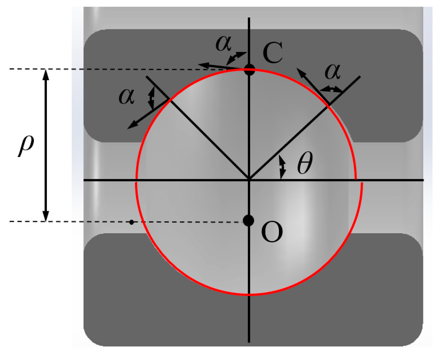
2.1. Logarithmic Spiral Raceway and Raceway Parameter Design

The raceway of a logarithmic spiral bearing is a logarithmic spiral, as shown in Figure 1. The equation of a logarithmic spiral in polar coordinates can be expressed as:
  r = r o e k θ
where r is the polar diameter, ro is the initial polar diameter, θ is the angle, and k is the constant growth rate, all satisfying:
  cot α = k
where α is the strike angle.
As shown in Figure 1, assuming that the contact point C is in the center of the channel and the instantaneous curvature of the raceway is 1/ρ, the second derivative of point C can be expressed as the instantaneous curvature ρ:
  ρ = k 2 + 1 · r o e k θ
The instantaneous raceway curvature coefficient f can be expressed as:
  f = ρ D w
where Dw is the diameter of the ball.
The curvature coefficient of inner and outer raceways can be expressed as:
  f x = r o e n x k k 2 + 1 D w x = i , o ; n i = 1.57 , n o = 4.71
From Equations (1), (2), and (5), it is knowable that the logarithmic spiral parameters, ro, k, and ρ, are only related to the curvature coefficient f of the contact point channel, the strike angle α, and the diameter Dw of the steel ball. If the curvature coefficient f of the contact point channel, the strike angle α, and the diameter Dw of the steel ball are determined, the logarithmic spiral raceway parameter equation can be determined.

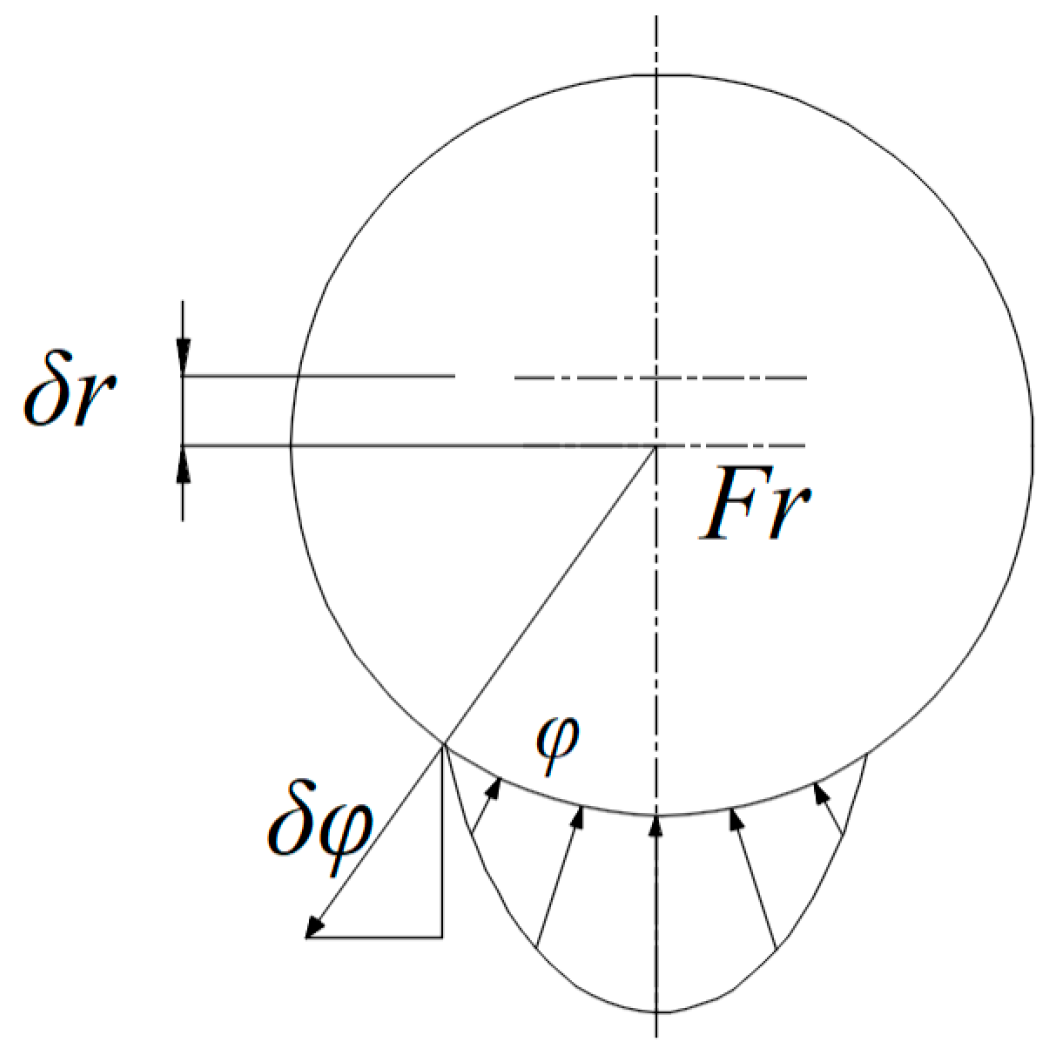
2.2. Contact Stress Analysis

As shown in Figure 2, under the action of radial load Fr, the radial displacement of the inner ring is δr and the radial contact displacement at the angle φ is:
  δ φ = δ r c o s φ 1 2 P d
where Pd is the radial clearance.
According to the Hertz contact theory, the contact load here is:
  Q φ = K n δ φ n ; δ φ > 0 Q φ = 0 ; δ φ 0
where Kn is the contact stiffness coefficient between the roller and the raceway, which can be expressed as:
  K n = 1 ( 1 / K i ) 3 + ( 1 / K 0 ) 3 1 3
The equations of the radial force balance of bearings are as follows:
  F r = i = 1 Z   Q φ i c o s φ i = K n i = 1 Z   ( δ r c o s φ i 1 2 P d ) 1.5
where Z is the number of rolling elements; i = 1,2,3,…, Z.

2.3. Fatigue Life Model of Logarithmic Spiral Bearing

According to Lundberg and Palmgen’s theory [27], the fatigue life of the roller in contact with the raceway point is determined by the following:
  L 10 x = Q c x Q e x 3
The rated dynamic load Qcx of the raceway of bearing can be expressed as:
  Q c x = 98.1 Φ x 0.41 Ψ D w 2.1 Z 1 / 3 ,   ( x = i , o )
The geometric parameters are shown in Equation (11):
  Φ x = 2 r x 2 r x D w , Ψ = ( D m D w ) 1.39 ( D m + D w ) 1 / 3 D m 1.3567
r x = r o e cot α n x x = i , o ; n i = 1.57 , n o = 4.71
The equivalent contact load Qex of bearing can be expressed as:
  Q e x = 1 Z j = 1 Z   Q ϕ x 3 1 / 3
The overall fatigue life of the bearing can be expressed as:
  L 10 = ( L 10 i 10 9 + L 10 o 10 9 ) 0.9

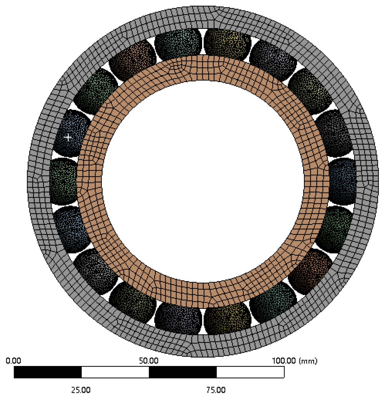
3. Verification of Fatigue Life Model

This study focuses on a logarithmic spiral bearing, with its key structural parameters summarized in Table 1. The researchers used these parameters to develop a detailed three-dimensional bearing model and imported it into ANSYS 2022 R1 Workbench for finite element analysis. The meshing process employed tetrahedral elements for the steel balls and hexahedral elements for the inner and outer rings. The researchers set the mesh size to 1 mm for the steel balls and 2 mm for the rings to balance computational efficiency and simulation accuracy. The researchers generated a final model containing 444,084 elements and 696,370 nodes, as illustrated by the mesh distribution in Figure 3. The outer diameter (130 mm), inner diameter (75 mm), and width (25 mm) of all bearings are constant to eliminate the interference of size effect on simulation results.
The outer ring’s raceway is set to be completely fixed, and the inner ring retains the freedom of rotation and limits the axial displacement. Refer to Table 2 for bearing material parameters and create contact pairs (36 pairs in total) between each ball and the raceway of the inner/outer ring. The raceway surface is the target surface, the spherical surface is the contact surface, and the friction coefficient is set to 0.1. The radial load is applied to the inner ring according to the parameters in Table 3, and the direction is negative (vertical downward) on the Y axis. Refer to Table 3 for raceway parameters of the logarithmic spiral, and the radius calculation of the raceway can be calculated by Equation (13).
FE simulations were conducted under the parametric conditions specified in Table 3 with uniform zero radial clearance to validate the static mechanical model. As depicted in Figure 4, the FE-derived contact stress demonstrated remarkable congruence with analytical predictions, exhibiting a maximum relative deviation of 8.2% within acceptable engineering tolerances. The remarkable agreement between FE simulations and analytical solutions substantiates the validity of the modeling assumptions, particularly the Hertzian contact hypothesis and quasi-static loading conditions.

4. Analysis and Discussion
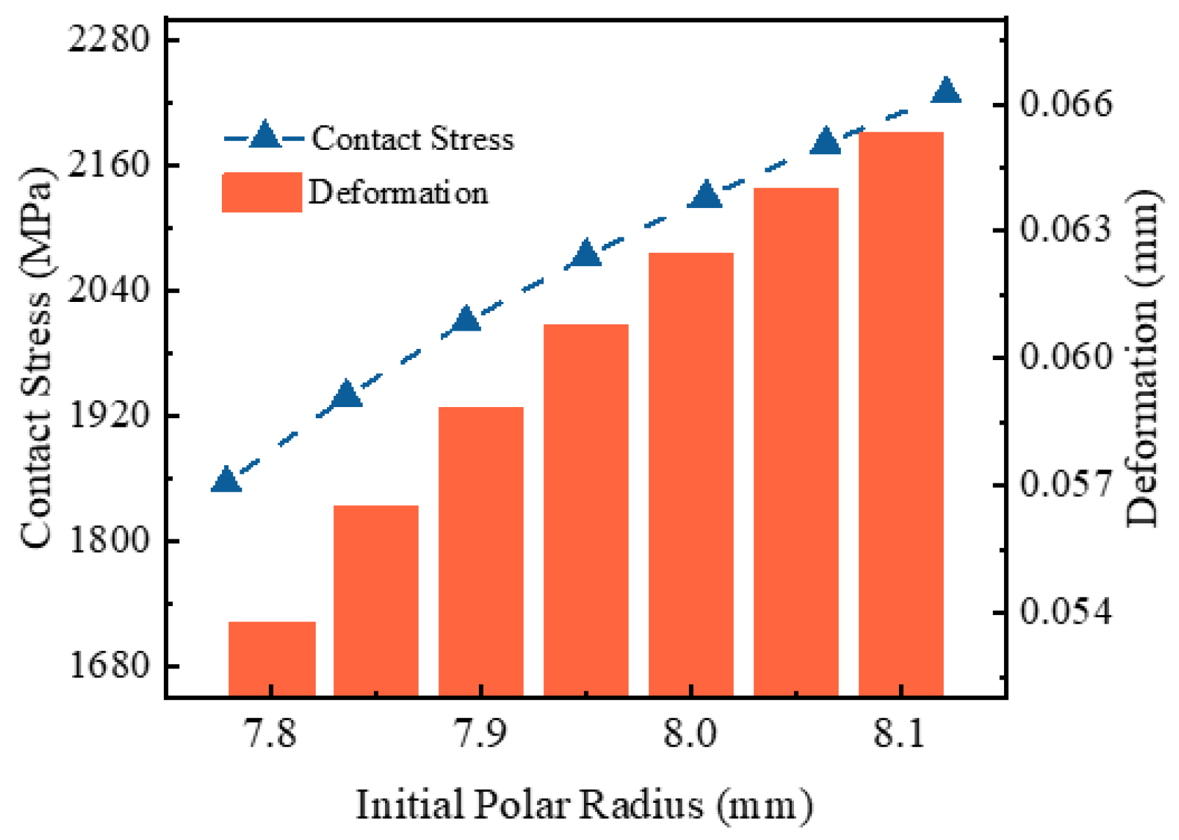
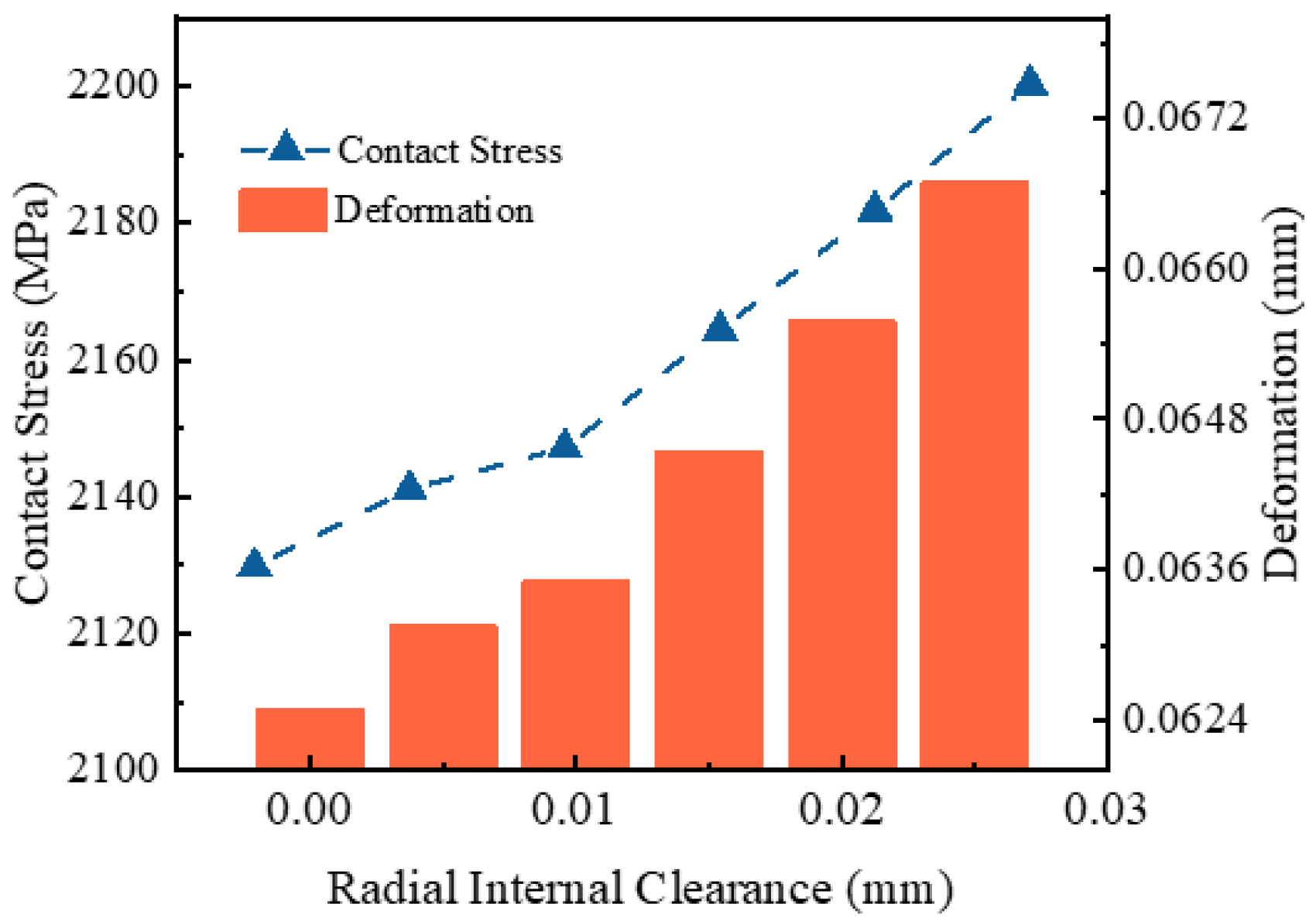
Applying the developed fatigue life model, parametric studies were conducted on logarithmic spiral bearings to investigate the effects of raceway geometry on mechanical performance and fatigue life. Under a 10 kN radial load condition, we analyzed systematic variations in the strike angle α (82–85°) and initial polar radius ro (7.8–8.1 mm) to quantify their impacts on stress distribution and fatigue failure modes.

4.1. Contact Stress

Figure 5 illustrates a significant reduction in maximum contact stress and deformation as the strike angle α increases. When the strike angle α increases from 82° to 85°, the contact stress decreases by 22.8%, while the elastic deformation drops by 21.2%.
This trend results from the geometric influence of the strike angle α on local curvature. With a constant ball diameter, increasing the strike angle α reduces the local radius of curvature at the contact point between the ball and the raceway. This change enhances the conformity at the contact interface and enlarges the effective contact area. According to classical contact mechanics, a larger contact area under constant load leads to lower contact stress and smaller elastic deformation. This theoretical understanding explains the observed reduction in both stress and displacement.
Figure 6 reveals a clear upward trend in both maximum contact stress and deformation as the initial polar radius ro increases. When the initial polar radius ro rises from 7.8 mm to 8.1 mm, the contact stress increases by 20.01%, and the deformation grows by 21.4%. This phenomenon arises from the change in local curvature at the contact region. While keeping the ball diameter constant, increasing the initial polar radius ro enlarges the local radius of curvature at the contact point. This geometric alteration reduces the conformity between the ball and the raceway, thereby decreasing the effective contact area. According to Hertzian contact theory, a smaller contact area under the same load leads to higher contact stress and greater elastic deformation.
Figure 7 illustrates a gradual increase in maximum contact stress and the corresponding deformation as the radial clearance increases. When the radial clearance δ rises from 0 to 0.025 mm, the contact stress grows by 3.3%, and the elastic deformation increases by 6.7%. This phenomenon can be attributed to the reduced number of rolling elements participating in load sharing under larger clearances. The load distribution mechanism within the bearing undergoes significant changes with clearance variation.
At zero radial clearance, the bearing achieves optimal load distribution where the applied radial load is uniform distribution rolling elements, resulting in lower contact stress on each element. However, increasing clearance creates a “load zone” with a reduced angular extent, leaving fewer rolling elements in effective contact to support the load. It leads to a load on fewer rolling elements, increasing the contact stress of the bearing.

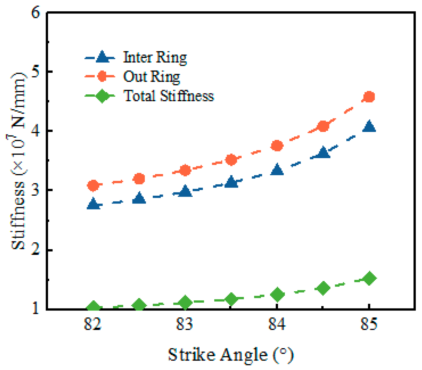
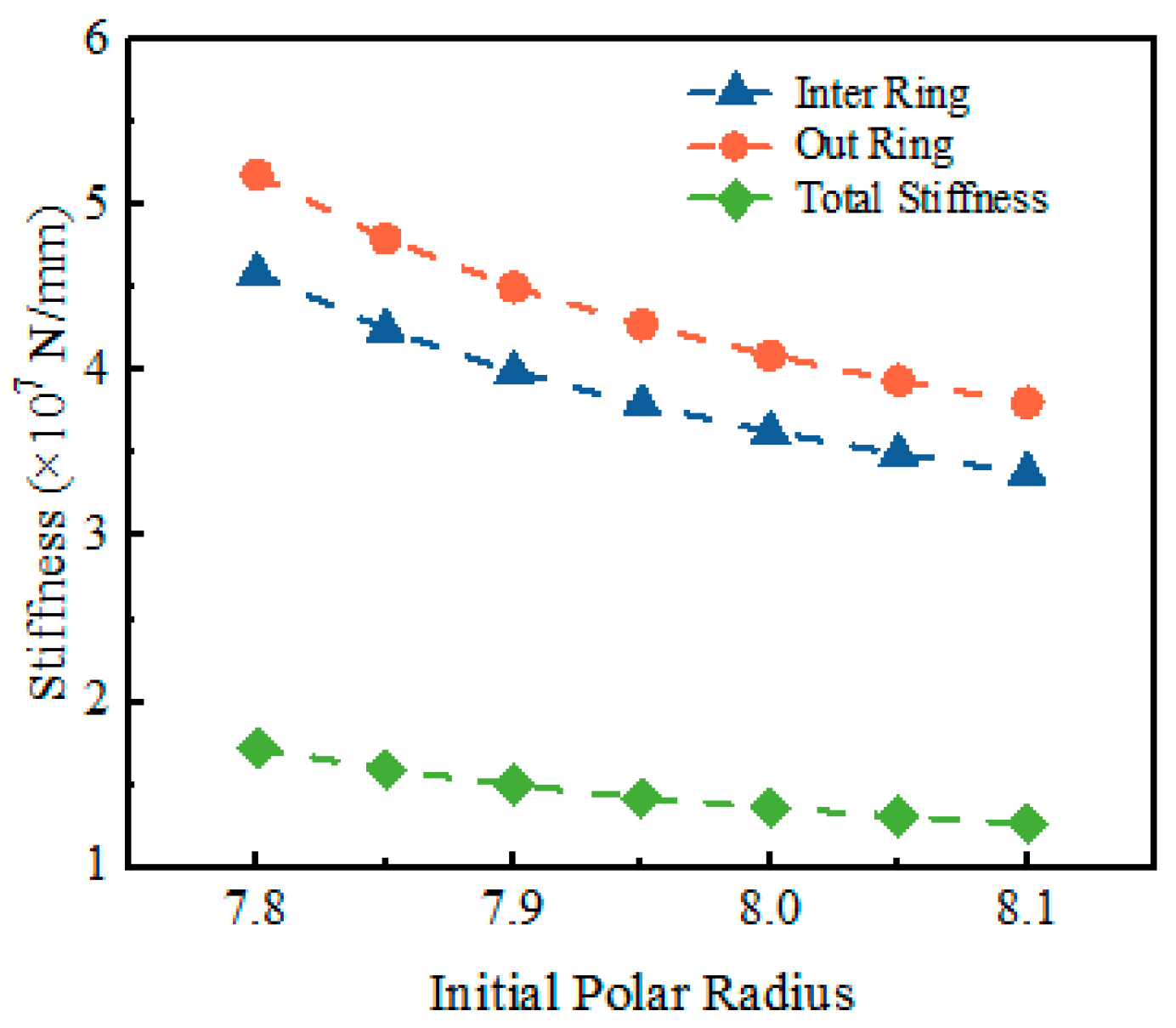
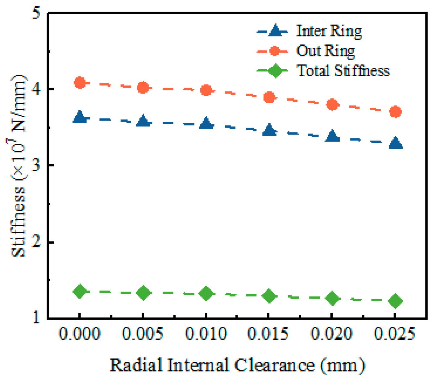
4.2. Radial Stiffness

Figure 8 demonstrates that, under a constant radial load of 10 kN, the bearing stiffness increases with the strike angle α. As the strike angle α rises from 82° to 85°, the stiffness increases by 48.5%. This increase stems from the evolution of contact geometry. A larger value of the strike angle α improves the local curvature at the contact interface, which promotes better load support and reduces Hertzian contact deformation between the ball and the raceway. This reduced compliance leads to a higher overall stiffness of the bearing assembly.
The total bearing stiffness remains lower than the inner and outer raceway contact stiffness throughout the test range. The outer raceway consistently exhibits greater stiffness than the inner raceway. This difference arises from the distinct stress distribution at the contact interfaces. Due to geometric factors and boundary constraints, the ball–outer raceway interface typically experiences lower contact stress and deformation than the ball–inner raceway interface, resulting in higher local rigidity. Moreover, the relatively constant stiffness difference between the inner and outer rings as the strike angle α increases indicates a similar evolution in contact conditions at both interfaces.
Figure 9 shows that, under a constant radial load of 10 kN, the bearing stiffness gradually decreases as the initial pole radius ro increases. When the initial pole radius ro increases from 7.8 mm to 8.1 mm, the stiffness drops by 26.2%. This decline appears most pronounced at smaller pole radii, while the rate of decrease slows with further increases in the radius. This trend reveals a nonlinear relationship between the initial geometry and the overall bearing stiffness.
The observed reduction in structural stiffness is driven by alterations in contact geometry, which stem directly from deviations in the initial pole radius ro during component fabrication. As the radius increases, the curvature at the ball–raceway contact region decreases, leading to less favorable load distribution. This geometric alteration increases Hertzian contact stress and local deformation, reducing the effective contact stiffness.
Figure 10 illustrates that, under a constant radial load of 10 kN, the bearing stiffness decreases as the radial clearance increases. When the radial clearance δ increases from 0 to 0.025 mm, the stiffness drops by 8.8%. This reduction primarily results from the impact of clearance on the d load distribution among rolling elements. As the clearance increases, the ball–raceway contact becomes delayed, and fewer balls carry the load, which causes a shift in load concentration and reduces the bearing system’s overall stiffness. From a contact mechanics perspective, introducing clearance reduces the initial contact preload and weakens the elastic coupling between the raceway and the rolling elements. As a result, under the same external load, the contact deformation increases significantly, further lowering the system’s ability to resist radial displacement.
As the radial clearance increases, the stiffness reduction curve gradually flattens, indicating that the additional impact on stiffness becomes negligible beyond a certain clearance threshold. Compared to the effects of the strike angle α (Figure 8) and the initial polar radius ro (Figure 9), the influence of radial clearance on bearing stiffness is the least significant. The minor role of radial clearance variations in stiffness performance compared to geometric profile parameters like the strike angle α and polar radius ro suggests that, in the design of logarithmic spiral bearings, moderate adjustments to clearance have a limited influence on load distribution and mechanical behavior. In summary, although increasing radial clearance reduces stiffness due to deteriorated load distribution, its effect is less pronounced than the strike angle α or polar radius ro. These findings highlight that optimizing the raceway geometry provides a more effective approach to enhancing stiffness than merely minimizing clearance.

4.3. Fatigue Life

As shown in Figure 11, fatigue life increases significantly with the rising strike angle α, exhibiting a clear nonlinear growth trend. When the strike angle α increases from 82° to 85°, fatigue life improves by a factor of 15.6. Specifically, increasing α from 82° to 83.5° raises the fatigue life from 25.09 × 10³ h to 68.81 × 10³ h, an approximately 1.74-fold improvement. In contrast, a further increase from 83.5° to 85° extends the life to 416.99 × 10³ h, a roughly 5.06-fold increase. This nonlinear amplification indicates that fatigue life becomes increasingly sensitive to the strike angle α variations at higher angular ranges.
The analysis suggests that a larger strike angle α increases the contact radius between rolling elements and raceways, enlarging the effective contact area. A larger contact area reduces the maximum Hertzian contact stress under constant load, lowering the subsurface shear stress amplitude closely associated with fatigue initiation. This stress reduction prolongs the rolling contact fatigue life, consistent with predictions from classical life models such as the Lundberg–Palmgren theory. The accelerated life improvement at the higher strike angle α indicates a threshold effect once the contact geometry reaches a favorable configuration; the resulting stress reduction yields disproportionately greater benefits for fatigue life.
As shown in Figure 12, fatigue life exhibits a distinct nonlinear decreasing trend with the increase in the initial pitch radius ro. When the initial radius ro increases from 7.8 mm to 8.1 mm, the fatigue life drops by as much as 86.9%. Specifically, increasing ro from 7.8 mm to 7.95 mm reduces the life from 909.50 × 10³ h to 263.55 × 10³ h, an approximately 2.45-fold decrease. In contrast, a further increase from 7.95 mm to 8.1 mm decreases from 263.55 × 10³ h to 119.05 × 10³ h, corresponding to a 1.21-fold drop. The heightened sensitivity of fatigue life to small increments of ro in the lower range—compared to its behavior at higher values—demonstrates the strong nonlinear relationship between this geometric parameter and bearing life. Specifically, a 0.05 mm increase in ro from 7.8 mm to 8.0 mm may reduce the lifespan by 25.4%, whereas the same incremental change above 8.0 mm yields a less than 10% reduction. The observed behavior can be attributed to the geometrical changes in the contact interface.
As the initial pitch radius ro increases, the contact radius between the rolling element and the raceway decreases, reducing the effective contact area. Under constant loading conditions, a smaller contact area leads to elevated maximum Hertzian contact stress. Higher contact stress accelerates the initiation and propagation of fatigue cracks, ultimately shortening life. Moreover, the nonlinear reduction indicates that at lower values of ro, even minor increases have a disproportionately large effect on fatigue life, whereas this sensitivity diminishes at higher values.
As shown in Figure 13, fatigue life decreases with the increase in radial clearance. When the radial clearance δ increases from 0 to 0.025 mm, the fatigue life is reduced by 26.3%. Specifically, under zero clearance, the bearing achieves its maximum load-carrying contact area, resulting in the minimum load per rolling element and a corresponding lifespan of 195.67 × 10³ h. However, as the clearance increases to 0.025 mm, the lifespan drops to 144.30 × 10³ h.
This reduction in fatigue life can be attributed to a decreased effective load-bearing area within the bearing due to increased clearance. A smaller contact area causes the load to become more concentrated on fewer rolling elements, thereby increasing the local stress on each ball. The elevated contact stress increases the likelihood of crack initiation and propagation, accelerating material degradation and shortening the bearing’s operational life. As a result, the increase in stress at the ball–raceway interface expedites the fatigue failure process, ultimately reducing the overall fatigue life.

4.4. Orthogonal Optimization Results

This paper conducted an orthogonal experimental design to quantify the effects of raceway parameters on bearing life and optimize overall bearing performance. The selected influencing factors included radial clearance, the strike angle α of the inner ring, the initial polar radius ro of the inner ring, the strike angle α of the outer ring, and the initial polar radius ro of the outer ring. Table 4 illustrates the orthogonal test design and its factor-level combinations.
Table 5 summarizes the orthogonal experimental groups and their associated test results. In Table 6, K1, K2, K3, K4, and K5 represent the average values of the objective function corresponding to each level of the respective factors. The range R, defined as the difference between the maximum and minimum average values across all levels for a given factor, is used to evaluate the relative influence of each factor. A larger value of R indicates a greater impact of the corresponding parameter on fatigue life.
This paper quantitatively evaluated the influence of each factor on bearing life by analyzing the R values. As shown in Table 6, the factors affecting the life of the logarithmic spiral bearing, in descending order of impact, are the strike angle α of the outer ring, the strike angle α of the inner ring, the initial polar radius ro of the inner ring, the initial polar radius ro of the outer ring, and the radial clearance. Among these, the strike angle α of the outer ring exhibits the most significant influence, followed by the strike angle α of the inner ring and the inner ring’s initial polar radius ro. In contrast, radial clearance is negligible in bearing longevity, enabling engineers to prioritize other design parameters over tight clearance control.
Further analysis of Table 6 demonstrates that the optimal configuration for each influencing factor corresponds to the parameter level with the maximum K value. Through comparative evaluation of these optimal levels, the study identifies the following parameter combination to maximize bearing performance: 0.02 mm radial clearance, 85° strike angle α for both inner and outer rings, and initial polar radii ro set at 7.8 mm (inner ring) and 7.9 mm (outer ring). Figure 14 compares the optimized parameters to validate this configuration with Test No. 16 (the longest fatigue life case in Table 4). The results reveal a 60.71% increase in bearing fatigue life under standard operating conditions, confirming the superiority of this configuration.
Based on the orthogonal experimental results, this paper determined the optimal structural parameter combination using an orthogonal table that incorporated selected influencing factors, the strike angle α, the initial pole radius ro of the rings, and radial clearance at multiple predefined levels.
However, certain limitations are inherent in the orthogonal optimization process. Sources of error may include the selection of structural parameters and their levels, as well as the number of test groups, which can affect the accuracy of the optimal solution. Despite these limitations, the optimized bearing structure parameters still offer valuable guidance for applications with moderate precision requirements or special constraints, particularly in non-standard bearing design. The parameter combinations obtained from orthogonal optimization can provide a meaningful reference for engineering design, contributing to improved design efficiency and reduced experimental costs.

5. Conclusions

Based on the geometric characteristics of the logarithmic spiral, this study derived parametric equations for the raceway profile and established a fatigue life prediction model grounded in static mechanical analysis.
(1)
The model’s accuracy was validated through finite element simulations, showing that the analytically derived maximum contact stress deviated by less than 8.3% from simulation results.
(2)
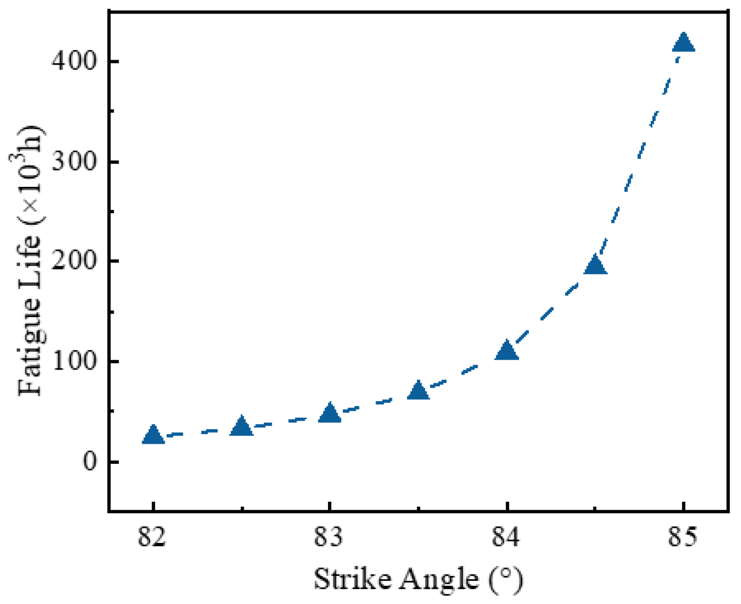
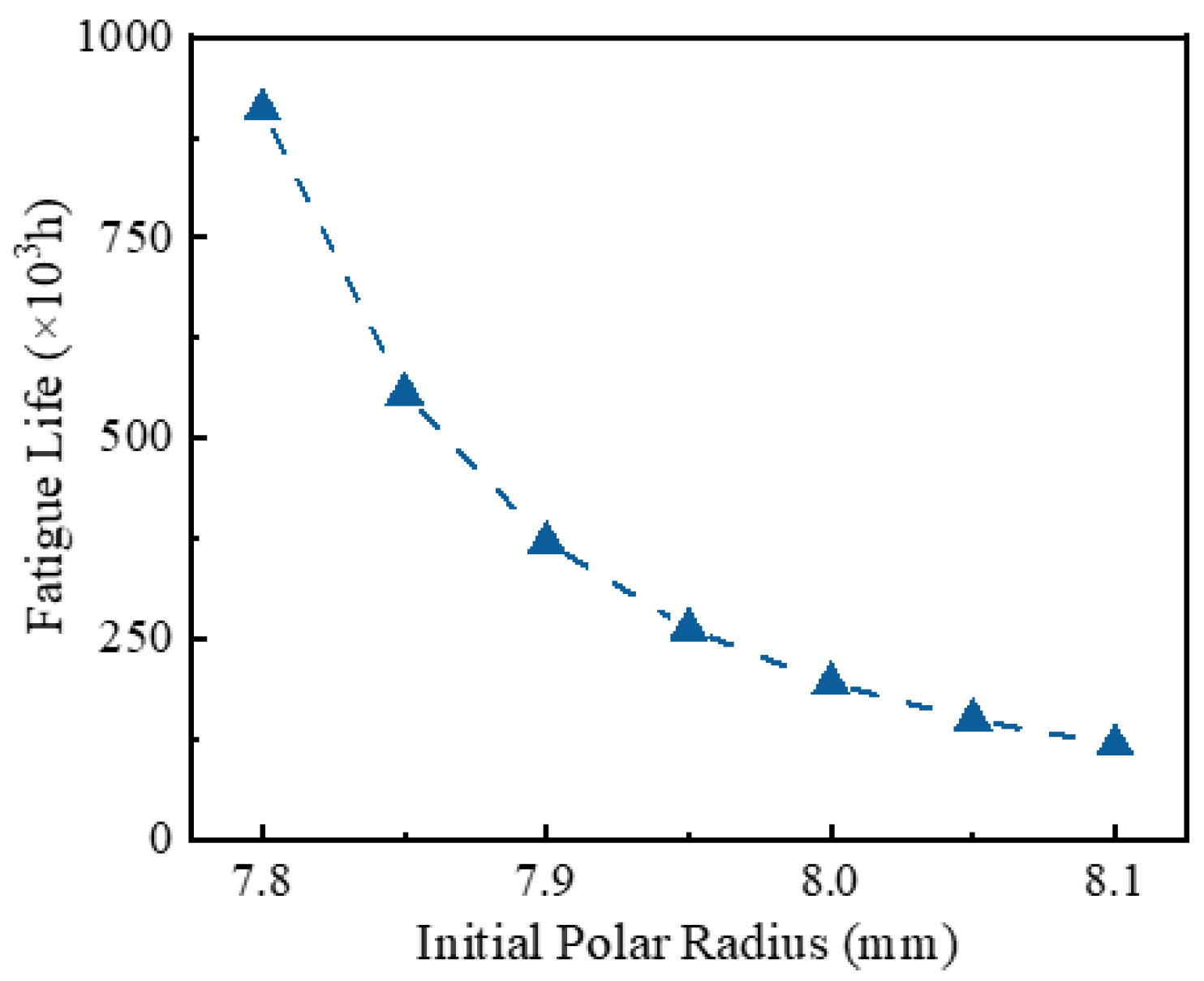
Building on this validated model, this paper systematically investigated the influence of the strike angle α, the initial polar radius ro, and radial clearance δ on bearing contact behavior and fatigue life. The results revealed pronounced nonlinear effects: an increase in the strike angle α from 82° to 85° led to a 22.8% reduction in contact stress, a 21.2% decrease in elastic deformation, a 48.5% increase in stiffness, and a 15.6-fold extension of fatigue life. Conversely, increasing the initial polar radius ro from 7.8 mm to 8.1 mm resulted in a 20.01% rise in contact stress and a 21.4% increase in deformation, accompanied by a 26.2% reduction in stiffness and an 86.9% decrease in fatigue life. Increasing radial clearance δ from 0 to 0.025 mm caused moderate increases in contact stress by 3.3% and deformation by 6.7% but led to an 8.8% reduction in stiffness and a 26.3% drop in fatigue life.
(3)
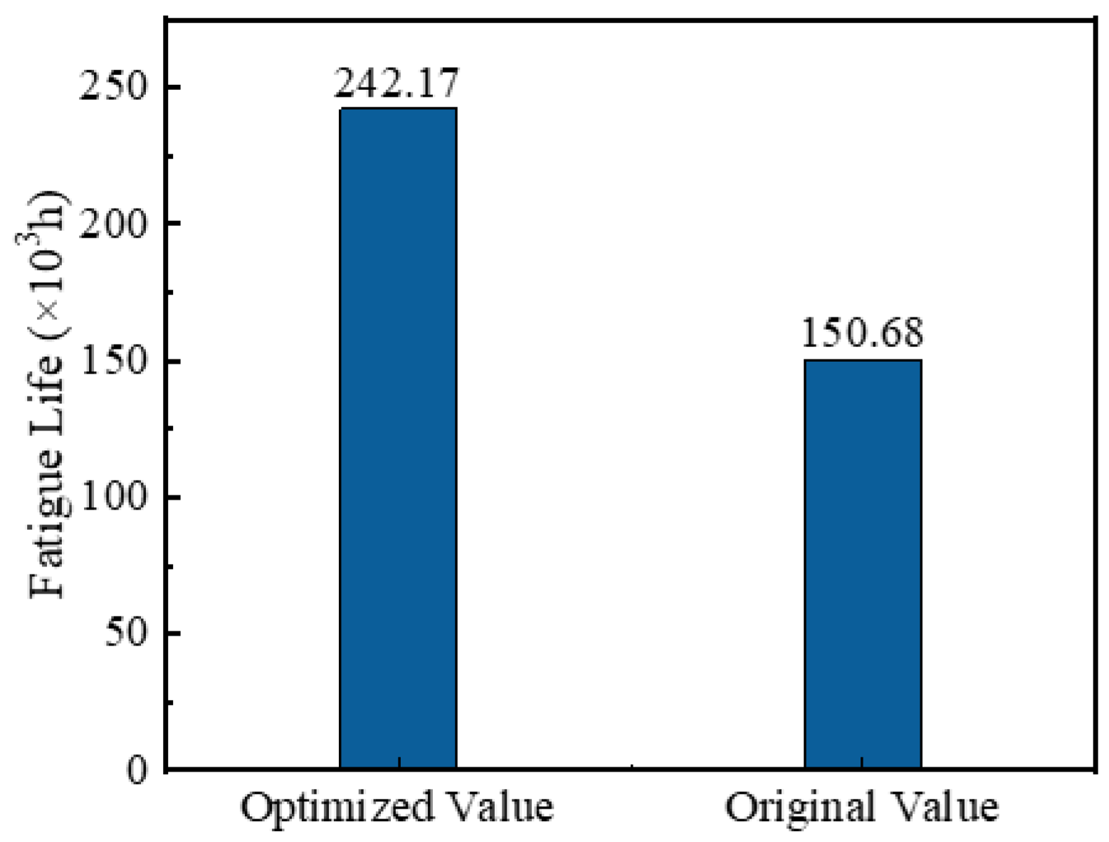
Orthogonal experimental analysis further identified the dominant factors affecting fatigue life in descending order of significance: the strike angle α of the outer race, the strike angle α of the inner race, the initial polar radius ro of the inner race, the initial polar radius ro of the outer race, and radial clearance. The optimal combination of clearance δ of 0.02 mm, inner race and outer race strike angles α of 85°, inner race initial polar radius ro of 7.8 mm, and outer race initial polar radius ro of 7.9 mm yielded a 60.71% increase in fatigue life.
These findings suggest that, in the design of logarithmic spiral raceways, prioritizing the optimization of the strike angle and initial polar radius ro is essential, particularly in applications with larger clearances. A design strategy that moderately increases the strike angle while reducing the polar radius ro can significantly enhance fatigue life under the experimental conditions examined. However, this study has limitations. The test data are obtained based on the bearing system with a specific size. Although the influence on the independence of the raceway parameters of the logarithmic spiral has been demonstrated, the macro-size changes, such as the outer diameter/inner diameter, may face differentiated machining error sensitivity, which requires targeted research combined with specific manufacturing processes. Future work should consider the potential influencing factors, such as rotational speed, lubrication state, temperature effect, material selection, wear behavior, macro-dimensional parameters, and manufacturing process, and combine the geometric parameters of the logarithmic spiral raceway to develop a more comprehensive design framework.

Author Contributions

Conceptualization, S.X.; writing—original draft preparation, X.Z.; writing—review and editing, S.X. and J.Z.; methodology, T.X. and X.Z. All authors have read and agreed to the published version of the manuscript.

Funding

This study was supported by the National Equipment Advance Research Grant Program Fund (Grant No. 6141C08).

Data Availability Statement

The original contributions presented in the study are included in the article; further inquiries can be directed at the corresponding author.

Acknowledgments

We are very grateful to Tranf Technology Co., Ltd. for its help in this study.

Conflicts of Interest

Tao Xu was employed by the company Tranf Technology Co., Ltd. The remaining authors declare that the research was conducted in the absence of any commercial or financial relationships that could be construed as a potential conflict of interest.

References

  1. Hu, Y.; Li, H.; Shi, P.; Chai, Z.; Wang, K.; Xie, X.; Chen, Z. A prediction method for the real-time remaining useful life of wind turbine bearings based on the Wiener process. Renew. Energy 2018, 127, 452–460. [Google Scholar] [CrossRef]
  2. Cavacece, F.; Frache, L.; Tonazzi, D.; Bouscharain, N.; Philippon, D.; Le Jeune, G.; Maheo, Y.; Massi, F. Roller bearing under high loaded oscillations: Life evolution and accommodation mechanisms. Tribol. Int. 2020, 147, 106278. [Google Scholar] [CrossRef]
  3. Rejith, R.; Kesavan, D.; Chakravarthy, P.; Murty, S.N. Bearings for aerospace applications. Tribol. Int. 2023, 181, 108312. [Google Scholar] [CrossRef]
  4. Zhao, X.; Guo, Y.; Ye, B. Kinematic characteristics and fault feature frequency of flexible thin-wall ellipse bearing. Mech. Syst. Signal Process. 2021, 149, 107222. [Google Scholar] [CrossRef]
  5. Rao, B.R.; Tiwari, R. Optimum design of rolling element bearings using genetic algorithms. Mech. Mach. Theory 2007, 42, 233–250. [Google Scholar]
  6. Waghole, V.; Tiwari, R. Optimization of needle roller bearing design using novel hybrid methods. Mech. Mach. Theory 2014, 72, 71–85. [Google Scholar] [CrossRef]
  7. Bu, C.G. Radial Clearance is key factor Affecting Roller Bearing Life Prediction in Tri-cone Bit. Adv. Mater. Res. 2008, 44, 233–238. [Google Scholar] [CrossRef]
  8. Dragoni, E. Optimal design of paired tapered roller bearings under centred radial and axial static loads. Mech. Ind. 2015, 16, 604. [Google Scholar] [CrossRef]
  9. Kim, S.-W.; Kang, K.; Yoon, K.; Choi, D.-H. Design optimization of an angular contact ball bearing for the main shaft of a grinder. Mech. Mach. Theory 2016, 104, 287–302. [Google Scholar] [CrossRef]
  10. Xie, Y.H.; Xu, L.X.; Deng, Y.Q. A dynamic approach for evaluating the moment rigidity and rotation precision of a bearing-planetary frame rotor system used in RV reduce. Mech. Mach. Theory 2022, 173, 104851. [Google Scholar] [CrossRef]
  11. Zander, M.; Otto, M.; Lohner, T.; Stahl, K. Evaluation of friction calculation methods for rolling bearings. Forsch. im Ingenieurwesen 2023, 87, 1307–1316. [Google Scholar] [CrossRef]
  12. Zhao, Y.; Chen, G.; Zhang, W.; Ding, Y. Research on Non-Circular Raceway of Single-Row Four-Point Contact Ball Bearing Based on Life Optimization. Appl. Sci. 2022, 12, 13027. [Google Scholar] [CrossRef]
  13. Ma, S.; Li, W.; Yan, K.; Li, Y.; Zhu, Y.; Hong, J. A study on the dynamic contact feature of four-contact-point ball bearing. Mech. Syst. Signal Process. 2022, 174, 109111. [Google Scholar] [CrossRef]
  14. Haug, E.J.; Kwak, B.M. Contcat stress minimization by contour design. Int. J. Numer. Methods Eng. 1978, 12, 917–930. [Google Scholar] [CrossRef]
  15. Lu, Z.; Lu, Y.; Deng, S. Study on Load Distribution Characteristics of Cylindrical Roller Bearings with Trilobe Raceways. Bearing 2016, 9, 1–6. [Google Scholar]
  16. Sun, X.; Deng, S.; Zhang, Y.; Chen, G. Study on vibration characteristic of trilobe raceway cylindrical roller bearing with elastic support. J. Mech. Transm. 2017, 41, 11–18. [Google Scholar]
  17. Deng, S.; Lu, Y.; Zhang, W.; Sun, X.; Lu, Z. Cage slip characteristics of a cylindrical roller bearing with a trilobe-raceway. Chin. J. Aeronaut. 2018, 31, 351–362. [Google Scholar] [CrossRef]
  18. Zhang, Z.; Deng, S.; Ju, H.W. Study on Processing for Non-Circular Raceway of Aerospace Trilobe Cylindrical Roller Bearings. Bearing 2019, 9, 13–17, 20. [Google Scholar]
  19. Zhang, X.; Luo, Y.; Zhang, Y. Influence of Raceway Shape on Mechanical Properties of Four-Point Contact Ball Bearings. Bearing 2014, 4, 40–42. [Google Scholar]
  20. Singh, A.P.; Agrawal, A.; Joshi, D. Contact Mechanics Studies for an Elliptical Curvature Deep Groove Ball Bearing Using Continuum Solid Modeling based on FEM Simulation Approach. IOSR J. Mech. Civ. Eng. 2016, 13, 1–11. [Google Scholar]
  21. Wang, S.; Du, J.; Chen, Y.; Wu, S.; Huang, Z. Influence of elliptical truncation on the raceway in a four-point contact pitching bearing. Eng. Fail. Anal. 2022, 141, 106711. [Google Scholar] [CrossRef]
  22. Mukutadze, M.A.; Lagunova, E.O. Mathematical Model of Flow of Lubricant and Molten Coating with Micropolar Rheological Properties in Running Clearance of Journal Bearing with Non-circular Bearing Surface Profile, Considering Pressure Dependence of Viscosity. In Proceedings of the 8th International Conference on Industrial Engineering, Sochi, Russia, 16–20 May 2022; Springer: Berlin/Heidelberg, Germany, 2022; pp. 587–597. [Google Scholar]
  23. Wang, Q.; Zhao, Y.; Wang, M. Analysis of contact stress distribution between rolling element and variable diameter raceway of cageless bearing. Appl. Sci. 2022, 12, 5764. [Google Scholar] [CrossRef]
  24. Li, Y.; Mo, J.; Zeng, J.; Xu, T.; Xu, S. Design and Dynamic Characteristics Analysis of a Novel Cageless Ball Bearing with Pure Rolling. J. Mech. Eng. 2023, 59, 256–269. [Google Scholar]
  25. Xu, T.; Li, Y.; Xu, S.; Mo, J. Experimental Study on Oil Interruption Performance of Novel Cageless Angular Contact Ball Bearings. J. Mech. Transm. 2022, 46, 112–116. [Google Scholar]
  26. Zhao, X.; Xu, S.; Xu, T.; Xu, Q.; Huang, K. Calculation Method and Experimental Study on Circumferential Total Clearance of Cageless Bearings. Lubricants 2024, 12, 238. [Google Scholar] [CrossRef]
  27. Lundberg, G.; Palmgren, A. Dynamic Capacity of Rolling Bearings. J. Appl. Mech. 1949, 16, 165–172. [Google Scholar] [CrossRef]
  28. Tong, R.; Yu, X.; Liu, Y.; Xia, Y.; Su, Y.; Jin, Y. Comparative analysis on properties of 8Cr4Mo4V steel for bearing after vacuum gas quenching and isothermal salt bath quenching. Heat Treat. Met. 2022, 47, 9–14. [Google Scholar]
Figure 1. Logarithmic spiral raceway and its geometric characteristics.
Symmetry 17 00889 g001
Figure 2. Radial displacement of rollers at any angular position.
Symmetry 17 00889 g002
Figure 3. Mesh generation results of the logarithmic spiral bearing model.
Symmetry 17 00889 g003
Figure 4. Comparison between numerical solution and simulation results.
Symmetry 17 00889 g004
Figure 5. Influence of strike angle on contact stress and deformation.
Symmetry 17 00889 g005
Figure 6. Influence of initial pole diameter on contact stress and deformation.
Symmetry 17 00889 g006
Figure 7. Influence of radial clearance on contact stress and deformation.
Symmetry 17 00889 g007
Figure 8. Variation of bearing stiffness with strike angle.
Symmetry 17 00889 g008
Figure 9. Variation of bearing stiffness with initial pole diameter.
Symmetry 17 00889 g009
Figure 10. Variation of bearing stiffness with radial clearance.
Symmetry 17 00889 g010
Figure 11. Variation trend of bearing life with strike angle.
Symmetry 17 00889 g011
Figure 12. Variation trend of bearing life with initial pole diameter.
Symmetry 17 00889 g012
Figure 13. Variation trend of bearing life with radial clearance.
Symmetry 17 00889 g013
Figure 14. Comparison of fatigue life results.
Symmetry 17 00889 g014
Table 1. Bearing parameters.
ParametersValueParametersValue
Inner diameter d (mm)75Width B (mm)25
Outer diameter D (mm)130Quantity Z18
Ball diameter Dw (mm)17.462
Table 2. Bearing material parameters [28].
MaterialElastic Modulus E/GPaPoisson’s Ratio νDensity ρ/(kg/m3)Ultimate Tensile Strength (Mpa)Yield Strength (Mpa)
8Cr4Mo4V2100.30780027402540
Table 3. Test parameters.
NumberFr (kN)α (°)ro (mm)
110837.8
213848
316857.9
410838
513847.9
616857.8
710837.9
813847.8
916858
Table 4. Factor level table of orthogonal test.
NumberRadial Clearance δThe Strike Angle α of the Inner RingThe Initial Polar Radius ro of the Inner RingThe Strike Angle α of the Outer RingThe Initial Polar Radius ro of the Outer Ring
10.010827.8827.8
20.015837.9837.9
30.020848848
40.025858.1858.1
Table 5. Group setting and results of orthogonal test.
NumberRadial Clearance δThe Strike Angle α of the Inner RingThe Initial Polar Radius ro of the Inner RingThe Strike Angle α of the Outer RingThe Initial Polar Radius ro of the Outer RingFatigue Life (h)
10.010827.8858.155.70
20.010837.9827.834.11
30.010848837.951.27
40.010858.184883.72
50.015827.9837.832.92
60.015837.8847.967.66
70.015848.185884.41
80.015858828.148.07
90.020828847.935.57
100.020838.1857.8123.46
110.020847.8828.141.01
120.020857.983889.02
130.025828.182813.16
140.025838838.122.15
150.025847.9847.895.73
160.025857.8857.9150.68
Table 6. Range of orthogonal test results.
NumberRadial Clearance δThe Strike Angle α of the Inner RingThe Initial Polar Radius ro of the Inner RingThe Strike Angle α of the Outer RingThe Initial Polar Radius ro of the Outer Ring
K156.234.3478.7634.0971.56
K258.2761.8562.9548.8476.30
K372.2768.1139.2770.6767.58
K470.4392.8776.19103.5641.73
R16.0758.5339.4969.4729.83
Disclaimer/Publisher’s Note: The statements, opinions and data contained in all publications are solely those of the individual author(s) and contributor(s) and not of MDPI and/or the editor(s). MDPI and/or the editor(s) disclaim responsibility for any injury to people or property resulting from any ideas, methods, instructions or products referred to in the content.

