Abstract
This study investigates the structural integrity and dynamic behavior of symmetry-optimized battery pack systems for new energy vehicles through advanced finite element analysis. It examines symmetry-optimized battery pack systems with mechanically stable and thermally adaptive potentials. Leveraging geometric symmetry principles, a high-fidelity three-dimensional (3D) model was constructed in SolidWorks 2023 and subjected to symmetry-constrained static analysis on ANSYS Workbench 2021 R1 platform. The structural performance was systematically evaluated under three critical asymmetric loading scenarios: emergency left/right turns and braking conditions, with particular attention to symmetric stress distribution patterns. The numerical results confirmed the initial design’s compliance with mechanical requirements while revealing symmetric deformation characteristics in dominant mode shapes. Building upon symmetry-enhanced topology configuration, a novel lightweight strategy was implemented by substituting Q235 steel with ZL104 aluminum alloy. While mechanical symmetry has been widely studied, thermal gradients in battery packs can induce asymmetric expansions. For example, uneven cooling may cause localized warping in aluminum alloy shells. This multiphysics effect must be integrated into symmetry constraints to ensure true stability. Symmetric material distribution optimization reduced the mass by 19% while maintaining structural stability, as validated through comparative static and modal analyses. Notably, the symmetric eigenfrequency arrangement in optimized modules effectively avoids common vehicle excitation bands (8–12 Hz/25–35 Hz), demonstrating significant resonance risk reduction through frequency redistribution. This research establishes a symmetry-driven design paradigm that systematically coordinates structural efficiency with dynamic reliability, providing critical insights for developing next-generation battery systems with balanced performance characteristics.
1. Introduction
In recent years, the high-quality development of China’s national economy has contributed to the rapid growth of the automotive industry, and China has steadily ranked as the world’s largest automotive production and consumption market for many years [1]. However, the rapid spread of traditional fuel vehicles, while bringing convenience, has also placed enormous pressure on energy and the environment [2,3]. The depletion of fuel resources has exacerbated the energy crisis, while tailpipe emissions pose a serious challenge to air quality and public health. To cope with these problems, the new energy vehicle industry has ushered in an opportunity for rapid development, in which new energy models represented by electric vehicles have gradually become the core of the market [4,5,6]. As a core component of new energy electric vehicles, the design and performance optimization of the battery pack plays an important role in improving the energy efficiency, safety, and service life of vehicles. In particular, it is important to assess whether the structure of the battery shell meets the impact strength and vibration performance as well as the impact on the lightweight of the whole vehicle [7]. Therefore, scientific modeling, accurate analysis, and optimization of the battery shell are some of the key topics for promoting the technological progress of new energy vehicles.
The current research on power battery packs for new energy vehicles focuses on lightweight design and optimization analysis methods. Researchers have widely adopted finite element analysis techniques, combined with structural optimization and dynamic analysis under typical working conditions, to study the strength, stiffness, and vibration performance of battery pack shells [8]. For example, the design of battery shells based on aluminum alloys, magnesium alloys, and carbon fiber composites is considered an effective way to achieve lightweighting. These materials not only feature high strength and low density, but also provide good corrosion resistance [9]. Relevant research points out that optimizing the shell structure and reducing redundant materials can achieve weight reduction while maintaining high strength and safety. Moreover, more attention is being paid to the innovative development of materials and the integration of multifunctional design in R&D. For example, some advanced enterprises and research institutes abroad are deeply exploring the application of carbon fiber composites and ceramic matrix composites, which have extremely low density, high strength, and excellent fatigue resistance [10,11,12].
Current research on finite element analysis and optimization of battery packs for new energy vehicles primarily focuses on various aspects, such as structural optimization, lightweight design, thermal management, vibration, and collision safety. The core objective of the research is to achieve maximum weight reduction by optimizing the structure and materials of the battery pack, while meeting the performance requirements for safety, strength, vibration, etc., so as to improve the range and overall performance of the vehicle. Among them, Shui L et al. [13] proposed an optimization design method in their study, aiming to improve the battery pack shell by minimizing the mass, maximizing the minimum intrinsic frequency, and minimizing the maximum deformation to improve the mechanical properties, but no sustainable approach was proposed. Xue N et al. [14], in their study, summarized an optimal design method for lithium–ion battery packs for hybrid vehicles. The method incorporates a variety of numerical optimization techniques to address the design challenges of hybrid integer nonlinear battery packs by combining several independent optimization procedures using a combination of gradient-free and gradient-based optimizers [15]. The approach significantly improved the overall performance of the battery pack under multiple safety and performance constraints but did not incorporate the most basic product equipment during the study. Y Lai et al. [16] explored the design of a novel liquid-mediated cooling system, with the aim of demonstrating that the scheme achieves lightweighting of the battery pack while maintaining efficient thermal management but did not provide accurate data to support the optimal design of the shell. In their article, Pilley S et al. [17] focus on how to develop smaller, lighter, and more cost-effective battery packs for global production based on design-for-assembly (DFA) principles. Using the Audi Q5 battery pack as an example, they analyzed its assembly process and applied DFA principles to the assembly design. By simplifying parts integration, reducing the number of components, and suggesting a modular design, the method provides a unified solution for the assembly of similar battery packs.
Taking the battery shell of new energy vehicles as the research object, this study adopts finite element analysis technology through geometric modeling and meshing, to carry out research on the structural performance of the battery shell under four typical working conditions, as well as the sixth-order analysis of the modal state [18,19,20]. The strength, stiffness, and vibration characteristics of the battery shell are comprehensively evaluated by simulating the mechanical response of the battery shell in the actual use environment. This study further combines the analysis results with a lightweight design approach to optimize the shell structure in order to minimize the material usage and weight while ensuring strength and safety. This not only improves the range of the vehicle, but also significantly reduces the production and operating costs, which meets the requirements of the modern automotive industry for green and efficient design.
2. Topology Optimization with Geometric Symmetry Constraints for Lightweight Battery Pack Structures
The structural design of new energy vehicle battery packs is related to the safety, durability, and efficiency of the battery system. This study aims to perform structural analysis and optimization through finite element analysis (FEA) [21,22,23,24]. The battery pack structure is complex and contains a large number of parts and detailed features, which, if not simplified, will lead to a large model, increased computation, and even the introduction of errors. Therefore, the key to model building is to balance accuracy and efficiency. The strategies adopted in this study include: retaining the complete geometric features of the key load-bearing structure; simplifying the details of non-critical areas, such as bolt connections and small holes; accurately defining material properties; and considering the actual assembly process. Through these methods, a finite element model is constructed that can reflect the key structural characteristics and has reasonable computational efficiency, laying the foundation for subsequent analyses.
2.1. Battery Pack Top Cover Design and Modeling
The structural design of the battery pack housing, as an important component of the battery pack, is of paramount importance. The design of the battery pack top cover first needs to ensure sufficient structural strength to meet the design requirements and protect the internal components from damage to a certain extent. Especially in extreme cases such as collision, the top cover should be able to withstand a certain impact force to prevent serious accidents, such as battery leakage, short circuit, or even explosion. At the same time, the dimensions of the top cover need to be reasonably designed according to the arrangement of the internal battery module, not only to meet the needs of accommodating the battery module and other key components, but also to ensure that there is enough space for installation in the chassis of the whole vehicle.
In this design, the top cover of the battery pack is not the main load-bearing component, but primarily plays the role of protection and sealing. Based on this, the design adopts a 3-mm thick stamped sheet metal part, with a length of 1890 mm, a width of 1340 mm, and a height of 120 mm, and the chosen material is Q235 steel plate, which has good strength, plasticity, and weldability, and meets the structural requirements of the top cover of the battery pack. In order to further improve the vibration resistance and intrinsic frequency of the top cover, and to avoid the occurrence of resonance phenomenon, stamping horizontal and vertical grooves are designed on the surface of the sheet metal parts. This structural design can effectively improve the stiffness of the top cover without significantly increasing the amount of material used, thus enhancing the overall strength of the top cover and improving its intrinsic frequency to a certain extent. Through reasonable structural design and material selection, this solution seeks to ensure the strength and safety of the top cover while taking into account lightweight design and cost-effectiveness.
SolidWorks is a powerful CAD modeling software that focuses on 3D and 2D design. It can flexibly construct complex geometric models to meet accuracy requirements, efficiently create 3D models that meet engineering needs, and quickly optimize them. SolidWorks seamlessly integrates with a variety of simulation and analysis software to support stress analysis and other simulations, providing convenient support for engineering validation. It is widely used in the aerospace and automotive industries, machinery manufacturing, and other industries. After confirming the size and structure of the top cover design, the battery pack top cover is modeled by SolidWorks, as shown in Figure 1.
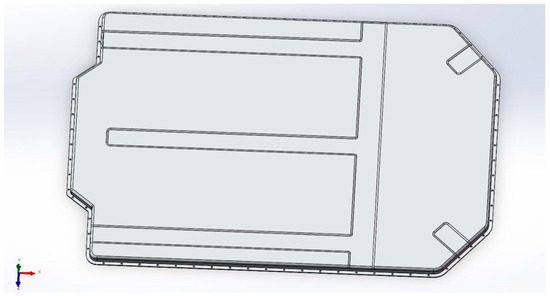
Figure 1.
3D model of the top cover of the battery pack.
2.2. Battery Lower Case Design and Modeling
The lower shell of the battery pack is the most critical load-bearing component in the battery pack structure, and its design is directly related to the overall strength, stiffness, and safety of the battery pack. Similar to the top cover of the battery pack, the design of the lower housing must first ensure sufficient structural strength to withstand the weight of the battery module and other components, and to protect the internal components from damage under various operating conditions. In addition, the lower shell also needs to have enough rigidity to ensure the overall stability of the battery pack and provide effective protection in the event of collision and other accidents. Therefore, in the design process, various factors need to be considered to make a reasonable structural design and material selection.
In this study, the lower shell of the battery pack, as the main load-carrying component, bears most of the load and impact force. In order to meet the requirements of strength, stiffness, and vibration resistance, this design solution adopts a pressed and formed steel plate with a thickness of 4 mm as the main material of the lower shell. Compared with the previous 3 mm thickness used for the lower cover, the 4 mm thickness used for the lower shell can significantly improve its load-carrying capacity, impact resistance, and overall stiffness. The material chosen is also Q235 steel plate, which has good strength, plasticity, and weldability to meet the structural requirements of the lower housing. In order to further enhance the overall strength and vibration resistance of the lower housing, reinforcement plates are welded inside the lower housing. The design of these reinforcement plates not only provides a fixed mounting position for each component, but also effectively improves the bending strength of the lower shell, thus enhancing the structural strength and deformation resistance of the entire battery pack. At the same time, the reinforcing plates can also be adjusted to achieve a reasonable use of the internal space and functional allocation of the battery pack by adjusting its position and number.
After confirming the design size and structure of the lower shell of the battery pack, the upper cover of the battery pack is modeled by SolidWorks, as shown in Figure 2.
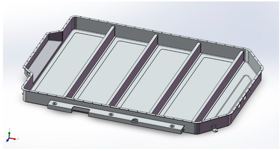
Figure 2.
3D model of the battery pack lower housing.
2.3. Confirmation of the 3D Assembly Model Linking Method
In the design of power battery packs, in addition to ensuring structural strength, it is equally crucial to achieve a high level of dust- and waterproof sealing and reliable connection to the body. This study proposes an innovative solution in battery pack housing design and chassis connection, aiming to simultaneously meet the requirements of sealing, structural strength, and installation convenience. In order to meet the requirements of IP67 or a higher level of dust and water resistance of the battery pack, the design has been carefully optimized in the connection part of the upper and lower shells. Similar to the traditional bolt fastening and sealing rubber gasket method, this solution uses multiple bolts to fasten the upper and lower housings to ensure a tight connection. However, unlike conventional designs, this solution employs a unique stepped structure and sealing groove design at the edge of the connection between the upper and lower housings. Through this stepped structure, the connecting surfaces of the upper and lower housings are able to achieve a tighter fit after the bolts have been tightened, and combined with the highly elastic sealing strip, water penetration is effectively prevented, and excellent sealing performance is maintained even when wading in the water or being washed by a high-pressure water jet. This design reduces the reliance on sealing tape and improves the stability of the sealing structure. At the same time, the design of the sealing grooves further enhances the load-bearing capacity of the sealing strips, ensuring that they are evenly distributed when the force is applied, thus improving the overall sealing effect.
In terms of the connection between the battery pack and the chassis, this study is different from the traditional bracket structure. The lower shell of the battery pack is not connected to the car body by welding brackets, but adopts an integrated lateral mounting structure, with extensions on both sides of the lower shell for connection to the car body. The lateral extensions of the lower housing are fastened to the longitudinal beams of the body or other chassis structure by means of multiple high-strength bolts, providing solid support and enhancing the integration of the battery pack into the body structure. This design helps disperse impact forces and utilizes the strength of the body to improve overall stability. In addition, the lateral extensions are equipped with mounting holes, simplifying the installation and removal of the battery pack, avoiding cumbersome welding of brackets, and reducing the overall structural weight of the assembly, as shown in Figure 3.
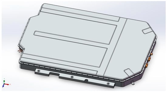
Figure 3.
3D model of battery packing ligand.
3. Symmetry-Constrained Finite Element Static Analysis for Lightweight Battery Pack Structures
Finite element static analysis is a numerical analysis method based on the finite element method for investigating the mechanical behavior of structures under static loads. By static loads, we mean loads that act on the structure and vary slowly or not at all, with time, such as gravity, pressure, and constraint forces. The purpose of static analysis is to determine the mechanical response of the structure under these static loads, such as displacement, stress, strain, etc., so as to assess the strength, stiffness, and stability of the structure, and to judge whether the structure meets the design requirements [25,26,27,28,29,30,31,32].
3.1. Finite Element Analysis of Battery Pack
As the core carrier of the vehicle’s energy, the structural safety and performance of new energy vehicle battery packs directly affect the overall reliability of the vehicle. During vehicle operation, the battery pack also faces complex and changing working conditions, such as impacts from the road surface, vibration during vehicle traveling, and extreme temperature changes, etc. These factors will bring challenges to the structural strength, stiffness, and thermal management performance of the battery pack. If the battery pack’s structural strength or stiffness is insufficient, it may lead to serious problems such as structural deformation, sealing failure, and even battery damage, which will directly threaten the safety and performance of the vehicle. Therefore, an in-depth analysis of the structural mechanical behavior of battery packs under various complex working conditions and optimization of the design on this basis is the key to ensure the safe and reliable operation of battery packs and safeguard the overall performance of the vehicle [32,33,34,35,36].
This study addresses the finite element analysis and optimization of battery packs, and finite element analysis plays a crucial role in this process. The main tasks of the study include:
(1) Structural strength analysis: through a detailed analysis of the stresses and displacements of the battery pack under different working conditions, to assess whether its strength meets the design criteria. This process can help identify possible weak points in the battery pack structure and provide key data to support design optimization.
(2) Vibration analysis: Free modal analysis is performed on the battery pack to study the vibration characteristics, intrinsic frequency, and vibration pattern of each order. This analysis helps to understand the possible vibration behavior of the battery pack during actual use, thus providing an optimized basis for structure and material selection and ensuring that the battery pack maintains good stability during long-term use.
3.2. Main Parameters of the Battery Pack
The battery pack consists of an upper housing, a lower housing, and an internal connection structure. The upper shell and lower shell are closely combined through the connection structure to form an overall protective shell. Among them, the lower shell, as the main load-bearing part, bears the weight of the battery module and road impact and needs to have high strength and stiffness; the upper shell is mainly responsible for sealing and protection, to prevent the entry of foreign objects. The shell material is Q235 steel plate, which has good strength, plasticity, and weldability, and can meet the requirements of the battery pack, and at the same time has a good cost advantage; the material parameters are shown in Table 1.

Table 1.
Battery pack housing material parameters.
This study evaluates the structural strength of power battery packs under typical working conditions through static finite element analysis and provides data support for lightweight design. During vehicle operation, the battery pack mainly bears the impact force generated by the shaking of the battery module under various working conditions. In this study, the inertial impact force generated by the movement of the battery module is regarded as a uniformly distributed static force, and is applied to the key nodes of the bottom plate and side walls of the lower box. This simplified method improves the computational efficiency while ensuring the analysis accuracy. With reference to relevant studies and national standards, three typical working conditions of sharp left turn, sharp right turn, and emergency braking on uneven road surfaces are selected for analysis in this study, and the load application of each typical working condition is shown in Table 2.
Table 2.
Main parameters of the whole vehicle.
3.3. Importing Finite Element Models
In order to perform the finite element analysis, a 3D model of the battery pack was first created in SolidWorks in this study. The model was exported as a generic .x_t format file in order to facilitate the import of the model into the FEA platform. The .x_t format file was then imported into ANSYS Workbench for finite element model construction. After being imported into ANSYS Workbench, the model was simplified appropriately in order to improve the computational efficiency while ensuring the analysis accuracy. Considering that the connection between the components of the battery pack is welding, all the components are simplified to be treated as a whole in the finite element analysis. In this way, complex contact relationships can be avoided in the model, reducing the amount of calculation and improving the efficiency of finite element analysis.
3.4. Finite Element Model Meshing
In this study, a partitioned mesh strategy is adopted to discretize the battery pack model, and an optimal balance of accuracy and computational efficiency is achieved in ANSYS Workbench: a 12 mm fine mesh is used for critical stress concentration areas such as bolt joints and reinforcing bar intersections, and a 15 mm coarse mesh is used for low stress areas such as planar housings. A mirrored mesh technique is used to ensure consistency in the node pattern of the symmetric features. This method reduces the total number of nodes by 22% (334,534) and ensures that the maximum stress change is less than 3% (see Section 3.5 for details of the validation), which significantly improves the solution efficiency while maintaining the computational accuracy (Figure 4).
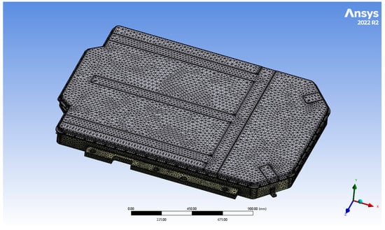
Figure 4.
Effect of mesh generation.
Through this partitioned grid division strategy, the problem of excessive computation caused by the global adoption of fine grids is avoided, while ensuring the computational accuracy of the key areas. After meshing, the final finite element model contains 334,534 nodes and 164,673 cells, and the overall effect of meshing is shown in Figure 4.
3.5. Typical Working Condition Analysis
In the complex and changeable driving environment, the motion state of new energy vehicles is constantly changing, and the loads on the battery pack become unpredictable. In order to comprehensively evaluate the structural performance of the battery pack, three representative typical conditions are selected for static analysis with reference to relevant studies and national standards, namely: extreme left turning on an uneven road surface; right turning on an uneven road surface; and emergency braking on an uneven road surface.
These three conditions can better simulate the extreme force conditions that may be encountered by the vehicle in the actual driving process. In the case of sharp turns, the battery pack is subjected to large lateral inertial and centrifugal forces, while the emergency braking condition subjects the battery pack to longitudinal inertial impact forces. At the same time, when driving on uneven road surface, the bumps and vibrations of the vehicle will also generate additional impact loads on the battery pack. By performing static finite element analysis of the battery pack under these typical conditions, the structural strength and stiffness of the pack can be fully evaluated and the weak points in the structure can be accurately identified.
By analyzing the battery pack under these severe conditions, if the strength and stiffness of the battery pack can meet the established design criteria, it can be proved that the battery pack has the ability to operate reliably for a long period of time under actual complex road conditions, thus verifying the reasonableness and applicability of the battery pack structure, and providing strong support for the subsequent structural optimization.
3.5.1. Emergency Left-Turn Conditions
When a new energy vehicle is traveling on an uneven road surface and makes an extreme left turn, the battery pack housing will be subjected to the gravity load of the battery module inside and the centrifugal force generated by the vehicle during the left turn, which will cause the battery module to shift to the right side, resulting in a lateral impact load on the battery pack housing. In addition, the bumps and vibrations caused by the uneven road surface will further aggravate the movement of the battery module and generate additional impact forces in the vertical and lateral directions.
The lower shell of the battery pack is subjected to the vertical load of the battery module:
The lower case of the battery pack is subjected to a lateral impact load:
where is the force to be applied in the working condition analysis, m is the mass of the battery pack module 310 kg, and g is the gravitational acceleration taken as 9.81.
Setting load constraints: fixed constraints on the two ends of the battery pack to support the movement of the frame fixing holes in the X, Y, Z direction, so that the end point cannot be shifted and turned to, as shown in Figure 5.
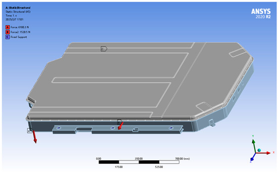
Figure 5.
Constraint and load application for emergency left-turn condition.
Setting loading load: after bringing the parameters into the formula calculation, it is learnt that a vertical downward force of 6180.3 N is applied at the acceptance of the lower case of the battery pack and the battery module, and at the same time, a force of 1520.5 N is applied at the right side of the battery pack, as shown in Figure 5.
Through ANSYS Workbench for the uneven road surface emergency left-turn conditions analysis and solution, the battery pack shell finite element simulation analysis of the displacement cloud and stress cloud results are shown in Figure 6 and Figure 7.
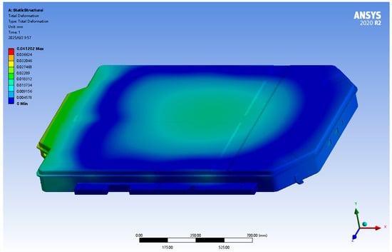
Figure 6.
Displacement cloud for emergency left-turn condition.
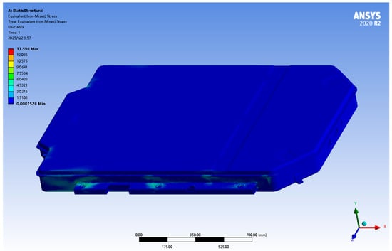
Figure 7.
Stress cloud for emergency left-turn condition.
From the analysis results of the emergency left-turn condition displacement cloud diagram in Figure 6, it can be seen that the battery pack shell displacement deformation mainly occurs in the tail. The maximum deformation occurs in the battery pack shell tail position, with a maximum deformation of about 0.041 mm, which is far less than the national regulations of 6 mm, which is determined to meet the steel strength requirements.
The stress map analysis results for the emergency left-turn working condition, as shown in Figure 7, indicate that the stress group is concentrated on both sides of the fixed bracket and box link, where the maximum stress position is 13.59 MPa, which is less than the battery pack material Q235 yield strength of 235 MPa. In the other areas, the stress values are lower, and in line with the performance specifications, meeting the strength requirements of the battery pack.
3.5.2. Emergency Right-Turn Condition
When a new energy vehicle is traveling on an uneven road surface and makes an emergency right turn, the battery pack housing will be subjected to the gravity load of the battery module inside and the centrifugal force generated by the vehicle during the right turn, which will cause the battery module to shift to the left side, resulting in a lateral impact load on the battery pack housing. In addition, bumps and vibrations caused by uneven road surfaces will further aggravate the movement of the battery module and generate additional impact forces in the vertical direction.
From Equation (1), it can be seen that the lower shell of the battery pack is subjected to a vertical load of 6180.3 N, and the lower shell of the battery pack is subjected to a transverse impact load of 1520.5 N.
Where is the force to be applied in the working condition analysis, m is the mass of the battery pack module 310 kg, and g is the value of gravity acceleration.
Setting load constraints: fixed constraints on the two ends of the battery pack support the frame fixed hole X, Y, Z, direction of movement, so that the end point cannot be displaced and rotated, as shown in Figure 8.
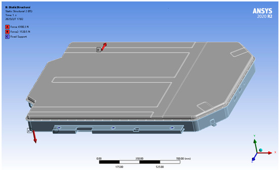
Figure 8.
Constraints and loads applied under emergency right-turn condition.
Setting the loading load: after inputting the parameters into the calculation formula, it is learnt that a force of 6180.3 N is applied vertically downward at the admissibility of the lower case of the battery pack and the battery module, and at the same time, a force of 1520.5 N is applied on the left side of the battery pack, as shown in Figure 8.
Using ANSYS Workbench, the battery pack shell finite element simulation analysis of displacement cloud and stress cloud results, under uneven road surface emergency right-turn conditions, are shown in Figure 9 and Figure 10.
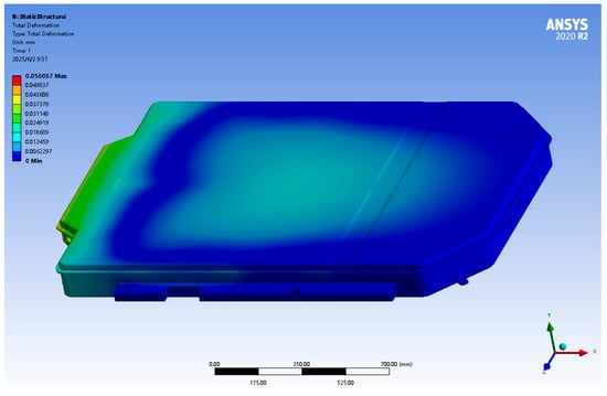
Figure 9.
Displacement cloud for emergency right-turn condition.
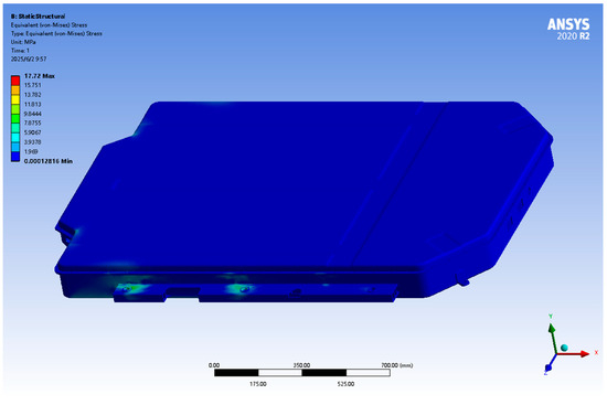
Figure 10.
Stress cloud for emergency right-turn condition.
From the results of the analysis of the displacement cloud diagram of the emergency right-turn condition in Figure 9, it can be seen that the displacement deformation of the battery pack shell mainly occurs in the tail. The maximum deformation occurs in the battery pack shell tail position, measuring about 0.05 mm, which is far less than the national regulation limit of 6 mm, which is determined to meet the steel strength requirements.
From Figure 10, the emergency right-turn working condition stress map analysis results show that the stress group is concentrated on both sides of the fixed bracket and the box link, where the maximum stress position is 17.72 MPa, which is less than the battery pack material Q235 yield strength of 235 MPa. In other areas, the stress values are lower, in line with the battery pack performance specifications and requirements.
3.5.3. Emergency Braking Conditions
When a new energy vehicle travels on an uneven road surface and undergoes emergency braking, the battery pack housing will be subjected to the gravity load of the battery module inside and the centrifugal force generated by the vehicle during emergency braking, which will cause the battery module to shift towards the front side, resulting in a lateral impact load on the battery pack housing. In addition, bumps and vibrations caused by uneven road surfaces will further aggravate the movement of the battery module and generate additional impact forces in the vertical direction.
From Equations (1) and (2), it can be seen that the vertical load of the battery module on the lower shell of the battery pack is 6180.3 N, which is the same as that on the lower shell of the battery pack.
The lower shell of the battery pack is subjected to lateral impact load:
where is the force to be applied in the working condition analysis, m is the mass of the battery pack module 310 kg, and g is the gravitational acceleration taken as .
Setting load constraints: fixed constraints on the movement of the X, Y, Z direction of the support frame fixing holes at both ends of the battery pack, so that no displacement or rotation can occur at that end point, as shown in Figure 11.
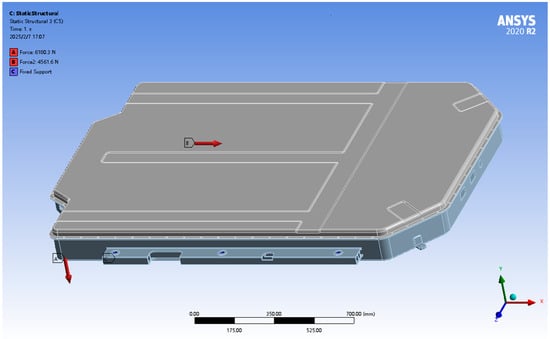
Figure 11.
Emergency braking condition constraints and load application.
Setting loading load: after inputting the parameters into the formula calculation, it is learnt that a force of 6180.3 N is applied vertically downward at the admissibility of the lower case of the battery pack and the battery module, and at the same time, a force of 4561.6 N is applied at the front part of the battery pack, as shown in Figure 11.
Through ANSYS Workbench analysis of emergency braking conditions on uneven road surfaces, the results of the displacement and stress maps from the battery pack shell finite element simulation are shown in Figure 12 and Figure 13.
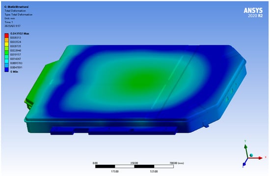
Figure 12.
Emergency braking condition displacement map.
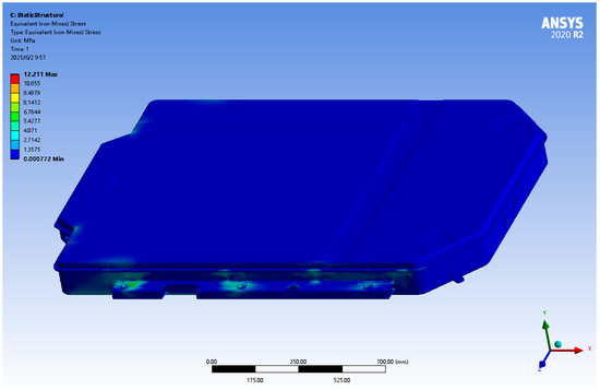
Figure 13.
Stress cloud for emergency braking condition.
From the results of the analysis of the displacement cloud diagram of the emergency braking turn condition in Figure 12, it can be seen that the displacement deformation of the battery pack shell mainly occurs in the center and at the tail. The maximum deformation occurs the battery pack shell tail position, measuring about 0.043 mm, which is far less than the national regulation limit of 6 mm, which is determined to meet the steel strength requirements.
From the emergency braking conditions stress map analysis results shown in Figure 13, it can be seen that the stress group is concentrated on both sides of the fixed bracket and the box link, where the maximum stress position is 12.21 MPa, which is less than the battery pack material Q235 yield strength of 235 MPa. In other areas, the stress values are lower, in line with the battery pack performance specifications and requirements.
4. Finite Element Modal Analysis of Battery Pack
Modal analysis is a crucial numerical analysis method that reveals the vibration characteristics of a battery pack under dynamic loading. The core objective of modal analysis is to determine the intrinsic frequency, vibration pattern, and damping characteristics of the battery pack, which are the basis for evaluating the dynamic response of the battery pack and the key to preventing resonance hazards. A battery pack is like a sophisticated musical instrument; different structural designs will have different intrinsic frequencies and vibration modes. When the vibration frequency of the battery pack is similar or equal to the frequency of the external excitation, resonance will occur, at which point the amplitude of the battery pack will increase significantly, which may trigger the loosening of the battery module and breakage of the connecting parts, and may even lead to the structural failure of the battery pack and potential safety hazards.
In order to ensure that the battery pack has good stability during the actual driving process, modal analysis is used to predict the dynamic behavior of the battery pack and identify potential resonance risks. For example, during vehicle traveling, the unevenness of the road surface, acceleration or braking of the vehicle, etc., may generate excitation frequencies. If these frequencies are close to the intrinsic frequency of the battery pack, resonance may be triggered, which may adversely affect the structural safety and performance of the battery pack. Therefore, in the design stage of the battery pack, it is necessary to carry out modal analysis to clarify its intrinsic frequency and vibration pattern, and then take effective structural optimization and vibration damping measures to avoid resonance phenomenon, and to ensure the long-term reliable operation of the battery pack.
Battery Pack Modal Analysis
In order to simulate that the structure cannot move freely in the process, the parts of the structure connected with fixed parts are usually set as fixed constraints. This constraint setting makes the finite element model more representative of real working conditions, thus ensuring that the calculated intrinsic frequency and vibration pattern more accurately reflect the structure’s real dynamic characteristics, providing a reliable data basis for subsequent structural optimization and safety assessment. The effect of the model constraints is shown in Figure 14.
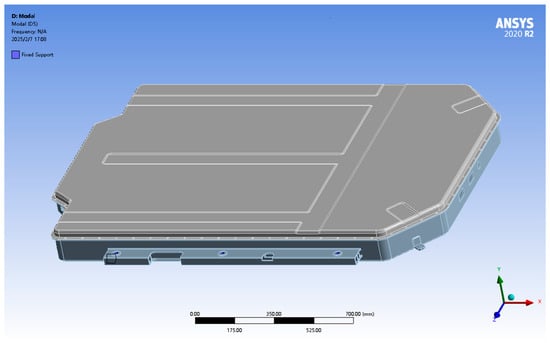
Figure 14.
Modal analysis constraints.
The modal analysis is solved by ANSYS Workbench for the constrained model and the first six orders of intrinsic frequency and vibration pattern maps are obtained as shown in Table 3 and Figure 15.
Table 3.
The first six natural frequencies.
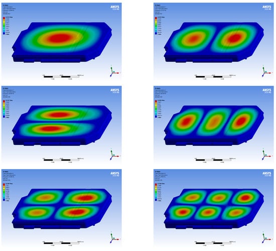
Figure 15.
Modal analysis of vibration patterns.
By performing the modal analysis of the battery pack shell, we obtained detailed information about its intrinsic vibration frequency. The analysis results show that the intrinsic frequency range of the battery pack shell is distributed between 16.54 Hz and 70.86 Hz. At lower frequencies, the main vibration mode of the battery pack shell is dominated by vertical bending deformation, and with the gradual increase in frequency, the shell begins to show the coupling of vertical bending and torsional deformation. Considering the vehicle in the actual driving process, the vibration frequency caused by uneven road surfaces is usually concentrated in the low-frequency range from 0 to 10 Hz. In this analysis, the first-order modal intrinsic frequency is 16.54 Hz, while the rest of the modal frequencies of each order are significantly higher than this value. This means that the intrinsic frequency of the battery pack shell has a significant deviation from the vibration frequency range that the vehicle is likely to encounter during driving. This design effectively avoids the risk of resonance of the battery pack structure during driving, thus providing a strong guarantee for the smoothness of vehicle driving and the safety of the battery pack. In conclusion, the results of the modal analysis show that this design effectively avoids the possibility of resonance of the battery pack shell during actual operation and ensures the dynamic stability of its structure.
5. Battery Pack Optimization
5.1. Optimization Programmer
The core idea of this study is to achieve the goal of battery pack lightweighting through material substitution, while satisfying strength and safety requirements. In the static analysis prior to the optimization of the design, it was found that the stress distribution of the battery pack shell was not uniform, and the high stress areas were mainly concentrated near the connectors and the sidewalls, while the stress levels in other areas were low. Based on this, in this study, the decision was made to use the lightweight aluminum alloy material ZL104 to replace the original Q235 steel. The performance parameters of the material selection are shown in Table 4. Considering that ZL104 aluminum alloy has a lower density and higher strength-to-weight ratio, it can effectively reduce the overall weight of the battery pack.
Table 4.
Material parameters.
5.2. Optimization of Simulation Calculations
5.2.1. Static Analyses
In order to verify the validity of the material replacement scheme, a static analysis of the battery pack model after the adoption of the new material (ZL104) was carried out by ANSYS Workbench. The same loads and boundary conditions as before optimization were used in this analysis to ensure comparable results.
The main objective of the analysis was to identify the stress distribution in the battery pack structure, focusing on high load areas such as connections and near the sidewalls, to determine if these areas have changed adversely as a result of the material substitution. Secondly, it is also necessary to evaluate the displacement changes of the battery pack under various operating conditions to check whether the overall stiffness and deformation of the battery pack meet the design requirements. Finally, the analysis of safety coefficients allows for a comprehensive assessment of the safety performance of the battery pack structure and determines the reliability of the structure under actual working conditions.
From the analysis results of the emergency left-turn condition displacement cloud diagram in Figure 16, it can be seen that the battery pack shell displacement deformation mainly occurs in the center and at the tail. The maximum deformation occurs in the battery pack shell tail position, measuring about 0.11 mm, which is far less than the national regulation limit of 6 mm, which is determined to meet the steel strength requirements.
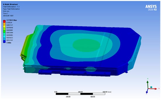
Figure 16.
Displacement cloud for emergency left-turn condition.
From the emergency left-turn working condition stress map analysis results shown in Figure 17, it can be seen that the stress group is concentrated on both sides of the fixed bracket and box link, with a maximum stress position of 13.6 MPa, which is less than the battery pack material ZL104 yield strength of 190 MPa. In other areas, the stress values are lower, in line with the battery pack performance specifications to meet the strength requirements.
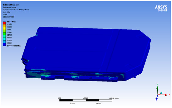
Figure 17.
Stress cloud for emergency left-turn condition.
From the analysis results of the displacement cloud diagram of emergency right-turn condition in Figure 18, it can be seen that the displacement deformation of the battery pack shell mainly occurs in the center and at the tail. The maximum deformation occurs in the battery pack shell tail position, measuring about 0.11 mm, which is far less than the national regulation limit of 6 mm, which is determined to meet the steel strength requirements.
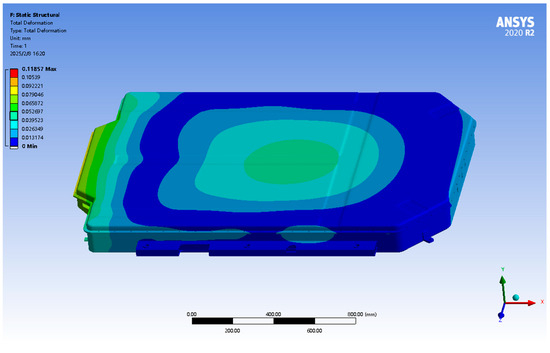
Figure 18.
Displacement cloud for emergency right-turn condition.
From the emergency right-turn working condition stress map analysis results shown in Figure 19, it can be seen that the stress group is concentrated on both sides of the fixed bracket and box link, with the maximum stress position being 13.2 MPa, which is less than the battery pack material ZL104 yield strength of 190 MPa. In other areas, the stress values are lower, in line with the battery pack performance specifications to meet the strength requirements.
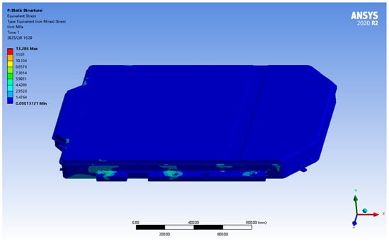
Figure 19.
Emergency right-turn working condition stress map.
From the analysis results of the emergency braking condition displacement cloud diagram in Figure 20, it can be seen that the battery pack shell displacement deformation mainly occurs in the center and the tail. The maximum deformation occurs in the battery pack shell tail position, measuring about 0.12 mm, which is far less than the national regulation limit of 6 mm, which is determined to meet the steel strength requirements.
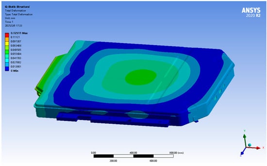
Figure 20.
Displacement cloud of emergency braking condition.
From the emergency braking conditions stress map analysis results shown in Figure 21, it can be seen that the stress group is concentrated on both sides of the fixed bracket and the box link, where the maximum stress position is 17.72 MPa, which is less than the yield strength of the battery pack material ZL104 190 MPa. In other areas, the stress values are lower, in line with the battery pack performance specifications to meet the strength requirements.
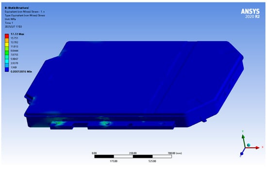
Figure 21.
Stress cloud for emergency braking condition.
5.2.2. Modal Analysis
In order to evaluate the effect of material substitution on the dynamic characteristics of the battery pack shell, in this study, a modal analysis of the battery pack shell with the new material (ZL104) was carried out in ANSYS Workbench. The same boundary conditions as before optimization were set for this analysis to ensure the comparability of the analysis results. The focus of the analysis was on verifying that the intrinsic frequency of the battery pack shell remains far from the range of excitation frequencies that may be encountered during the actual operation of the vehicle, in order to avoid possible resonance phenomena. At the same time, the modal analysis can further evaluate the stability and reliability of the battery pack shell under a dynamic environment after material replacement. In conclusion, this modal analysis aims to ensure that the material replacement does not adversely affect the dynamic performance of the battery pack and to verify the reasonableness of the optimized design.
By performing the modal analysis of the battery pack shell, as shown in Table 5 and Figure 22, we obtained detailed information about its intrinsic vibration frequency. The analysis results show that the intrinsic frequency range of the battery pack shell is distributed between 16.76 Hz and 71.44 Hz. At lower frequencies, the main vibration mode of the battery pack shell is dominated by vertical bending deformation, and with the gradual increase in frequency, the shell begins to show the coupling of vertical bending and torsional deformation. Considering the vehicle in the actual driving process, the vibration frequency caused by an uneven road surface is usually concentrated in the low-frequency range of 0 to 10 Hz. In this analysis, the first-order modal intrinsic frequency is 16.76 Hz, while the rest of the modal frequencies of each order are significantly higher than this value. This means that the intrinsic frequency of the battery pack shell deviates significantly from the vibration frequency range that the vehicle is likely to encounter during driving. This design effectively avoids the risk of resonance of the battery pack structure during driving, thus providing a strong guarantee for the smoothness of vehicle driving and the safety of the battery pack. In conclusion, the results of the modal analysis show that this design effectively avoids the possibility of resonance of the battery pack shell during actual operation and ensures the dynamic stability of its structure.
Table 5.
First six orders of intrinsic frequency.
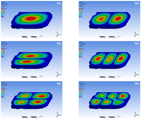
Figure 22.
Modal analysis shape diagram.
5.2.3. Optimizing Quality Assessment
In order to verify the lightweight design results of this study, a weight comparison analysis of the battery pack model before and after optimization was carried out using the quality assessment function of SolidWorks. The results show that the weight of the battery pack model before optimization was 47.4 kg, while the weight of the model after optimization was 38.1 kg. This indicates that the weight of the battery pack was successfully reduced by 9.37 kg, which is up to 19%, through the optimized design in this study. This significant lightweighting effect indicates that the optimized design in this study has achieved the goal of efficient lightweighting while ensuring the performance of the battery pack.
By comprehensively analyzing the optimization scheme in this study, we can draw the following conclusions: after replacing the material, the battery pack not only meets the requirements of structural strength and stiffness, but also verifies, through modal analysis, that there is a significant deviation between its intrinsic frequency and the excitation frequency commonly found in the actual operation of the vehicle, which effectively avoids the risk of resonance and ensures the dynamic stability of the battery pack. In addition, the weight of the optimized battery pack is significantly reduced, by 19%, compared to the pre-optimization design, demonstrating an excellent lightweight effect. Overall, the optimized design successfully achieves the lightweight target under the premise of ensuring the reliability of the battery pack performance, which provides an effective theoretical basis and practical reference for the lightweight design of battery packs for new energy vehicles.
6. Conclusions
This study took the new energy vehicle battery pack as its research object, and involved an in-depth study and optimization of its structural performance through the finite element analysis method. This paper describes in detail the structural design of the battery pack, the finite element analysis method, and the material replacement optimization scheme, and provides a comprehensive comparative analysis of the performance before and after optimization. The main conclusions of this study are as follow:
(1) By reviewing the domestic and international literature, in combination with actual design requirements, the basic requirements of safety, strength, stiffness, and lightweighting that the battery pack structure design must meet are clarified, laying a theoretical foundation for the subsequent finite element analysis and optimization. At the same time, an accurate model of the battery pack was established by the 3D modeling software SolidWorks, which provided the basis for the subsequent finite element analysis.
(2) In order to simulate the stress state of the battery pack under real working conditions, three typical working conditions were selected in this study: sharp left turn, sharp right turn, and emergency braking on an uneven road surface. The finite element analysis software ANSYS Workbench was used to carry out a static analysis on the model of the battery pack, so as to obtain the distribution of the stresses and displacement changes in each working condition. The results show that the structural strength of the battery pack before optimization meets the design requirements, but there is some space for lightweighting.
(3) In order to evaluate the dynamic characteristics of the battery pack, this study conducted a modal analysis of the battery pack to obtain its first six orders of intrinsic frequency and vibration pattern. The results show that the intrinsic frequency of the battery pack is far away from the common excitation frequency range during vehicle driving, which effectively avoids the occurrence of resonance phenomenon and ensures the structural stability of the battery pack.
(4) Multiphysics validation demonstrates that the symmetric design achieves superior thermal stress symmetry (asymmetry ratio of 1.17 under 20 °C gradient) compared to asymmetric alternatives, while the stamping process reduces production costs by 57% compared to additive manufacturing approaches.
(5) In order to achieve the lightweight goal of the battery pack, this study adopts a material replacement scheme, i.e., replacing the original Q235 steel plate with the lightweight aluminum alloy ZL104, and carries out static analysis and modal analysis for verification. The results of the comparative analysis show that the weight of the battery pack after material replacement is significantly reduced under the premise of ensuring strength and stiffness, and the dynamic characteristics remain good, which verifies the effectiveness of the material replacement scheme.
(6) By comparing the weight of the model before and after optimization, it was found that the weight of the optimized battery pack is reduced by 19%, indicating that this study has successfully achieved the goal of lightweighting the battery pack.
(7) The current steady-state thermal analysis and single-cycle simulation require further validation through transient coupled simulations and durability testing spanning >100,000 load cycles.
This study has made some progress in the finite element analysis and lightweight optimization of battery packs, and we are confident and looking forward to future research directions in order to further improve the overall performance of battery packs. An in-depth study of the thermal management of battery packs is merited since, in addition to structural strength and stiffness, thermal performance management is also a crucial aspect. Future research could consider combining thermal analysis with structural analysis to design a more efficient heat dissipation system. In the design of battery packs, not only should lightweighting be considered, but multiple factors such as strength, stiffness, thermal management, and cost should also be taken into account. Future research can try to introduce a multi-objective optimization method to obtain a more comprehensive optimization solution.
Author Contributions
Methodology, Y.L.; Software, J.T.; Validation, C.L.; Resources, G.T. All authors have read and agreed to the published version of the manuscript.
Funding
National Natural Science Foundation of China 51508304
Data Availability Statement
The original contributions presented in this study are included in the article. Further inquiries can be directed to the corresponding author.
Acknowledgments
We gratefully acknowledge the financial support of the New Energy Vehicle Intelligent Network Technology Shandong Province Higher Education Institutions Future Industry Engineering Research Centre Project.
Conflicts of Interest
The authors declare no conflict of interest.
References
- Chen, Y.; Liu, X.; Shan, Y.; He, T. Lightweight design of drive axle housing based on reliability. Int. J. Veh. Perform. 2020, 6, 294–309. [Google Scholar] [CrossRef]
- Zhang, C.; Li, Q.; Zhang, X.; Wang, X.; Chen, J.; Shen, X. Lightweight design of special axle hub based on ANSYS consider different working conditions for low carbon. Math. Probl. Eng. 2022, 2022, 3738996. [Google Scholar] [CrossRef]
- Stabile, P.; Ballo, F.; Mastinu, G. An ultra-efficient lightweight electric vehicle—Power demand analysis to enable lightweight construction. Energies 2021, 14, 766. [Google Scholar] [CrossRef]
- Kral, J.; Palko, M.; Pavlikova, L. Design and development of ultra-light front and rear axle of experimental vehicle. Open Eng. 2020, 10, 232–237. [Google Scholar] [CrossRef]
- Kim, K.J.; Lee, J.W. Light-weight design and structure analysis of automotive wheel carrier by using finite element analysis. Int. J. Precis. Eng. Manuf. 2022, 23, 79–85. [Google Scholar] [CrossRef]
- Su, H.; Ding, P.; Lang, B.; Wang, C.; Yi, J.; Liu, D. Lightweight Design of Suspension Balance-Axle Bracket Based on Nonlinear Strength Simulation and Experiment. InSociety Automot. Eng. (SAE)-China Congr. 2023, 1151, 539–549. [Google Scholar]
- Li, Q.; Tong, M.; Jia, M. Towards low carbon: A lightweight design of automotive brake hub. Sustainability 2022, 14, 15122. [Google Scholar] [CrossRef]
- Zhao, F. Finite-Element Analysis on Lightweight Material of Drive Axle Housin. J. Compos. Adv. Mater./Rev. Compos. Matériaux Avancés 2021, 31, 41–49. [Google Scholar]
- Huang, J. Research on Lightweight Design of Differentials for New Energy Passenger Cars; Hubei Institute of Automotive Industry: Shiyan, China, 2023. [Google Scholar]
- Yue, Y.Y.; Wang, H.; Liu, X.B. Lightweight design of outrigger structure of a heavy special vehicle. Automot. Parts Compon. 2023, 04, 64–66. [Google Scholar]
- Zheng, L.P. Lightweight design of new energy vehicle battery pack case based on finite element method. J. Langfang Norm. Coll. (Nat. Sci. Ed.) 2023, 23, 53–58. [Google Scholar]
- Qi, X.X.; Liu, Z.; Sui, T. Development and research on lightweight design of axles for commercial vehicles. Heavy Duty Veh. 2023, 04, 14–15. [Google Scholar]
- Shui, L.; Chen, F.; Garg, A.; Peng, X.; Bao, N.; Zhang, J. Design optimization of battery pack enclosure for electric vehicle. Struct. Multidiscip. Optim. 2018, 58, 331–347. [Google Scholar] [CrossRef]
- Xue, N.; Du, W.; Greszler, T.A.; Shyy, W.; Martins, J.R. Design of a lithium-ion battery pack for PHEV using a hybrid optimization method. Appl. Energy 2014, 115, 591–602. [Google Scholar] [CrossRef]
- Cicconi, P.; Landi, D.; Germani, M. Thermal analysis and simulation of a Li-ion battery pack for a lightweight commercial EV. Appl. Energy 2017, 192, 159–177. [Google Scholar] [CrossRef]
- Lai, Y.; Chudong, X.U. Lightweight design scheme for front subframe of new energy vehicle. Automot. Pract. Technol. 2023, 48, 19–25. [Google Scholar]
- Pilley, S.; Morkos, B.; Alfalahi, M. Integration and Modularity Analysis for Improving Hybrid Vehicles Battery Pack Assembly; SAE Technical Papers; SAE International: Warrendale, PA, USA, 2018. [Google Scholar]
- Topac, M.M.; Karaca, M.; Aksoy, B. Lightweight design of a rear axle connection bracket for a heavy commercial vehicle by using topology optimisation: A case study. Mechanics 2020, 26, 64–72. [Google Scholar] [CrossRef]
- Tian, G.D.; Cheng, Z.; Amir, M. An enhanced social engineering optimizer for solving an energy-efficient disassembly line balancing problem based on bucket brigades and cloud theory. IEEE Trans. Ind. Inform. 2022, 19, 7148–7159. [Google Scholar] [CrossRef]
- Xing, J.Q.; Zhen, Z.J. Research on the assessment method of bearing capacity of damaged continuous girder bridge under coupled vibration of vehicle and bridge. J. East China Jiaotong Univ. 2024, 45–54. [Google Scholar]
- Galos, J.; Sutcliffe, M. Material selection and structural optimization for lightweight truck trailer design. SAE Int. J. Commer. Veh. 2020, 12, 281–297. [Google Scholar] [CrossRef]
- Ding, X.; Liu, X. Modal Analysis of Automobile Wheels based on Lightweight Technology. J. Electr. Syst. 2024, 20, 353–364. [Google Scholar] [CrossRef]
- Zhang, Y.; Li, F.; Jia, D. Lightweight design and static analysis of lattice compressor impeller. Sci. Rep. 2020, 10, 18394. [Google Scholar] [CrossRef] [PubMed]
- Sonsino, C.M. Consideration of salt-corrosion fatigue for lightweight design and proof of aluminium safety components in vehicle applications. Int. J. Fatigue 2022, 154, 106406. [Google Scholar] [CrossRef]
- Krüger, D.; Gomes, A.C.; Schmauder, N.; Laporte, M.; Winkler-Höhn, R.; Kopp, G. Lightweight Design of the Extended Market Wagon-An Innovative Freight Wagon Developed in Fr8Rail 4, a Europe’s Rail Project. Int. Verkehrswesen 2022, 3, 54–57. [Google Scholar]
- Tian, G.D.; Lu, W.D.; Zhang, X.S. A survey of multi-criteria decision-making techniques for green logistics and low-carbon transportation systems. Environ. Sci. Pollut. Res. 2023, 30, 57279–57301. [Google Scholar] [CrossRef]
- Epasto, G.; Distefano, F.; Gu, L.; Mozafari, H.; Linul, E. Design and optimization of Metallic Foam Shell protective device against flying ballast impact damage in railway axles. Mater. Des. 2020, 196, 109120. [Google Scholar] [CrossRef]
- Li, D.; Tian, J.; Shi, S.; Wang, S.; Deng, J.; He, S. Lightweight Design of Commercial Vehicle Cab Based on Fatigue Durability. CMES-Comput. Model. Eng. Sci. 2023, 136, 421–445. [Google Scholar] [CrossRef]
- Ditzer, B.; Rosta, S.; Koopmann, J. Lightweight Design of Suspension Springs for Plug-in Hybrid and Battery Electric Vehicles. ATZ Worldw. 2022, 124, 46–51. [Google Scholar] [CrossRef]
- Li, J.; Tan, J.; Dong, J. Lightweight Design of front suspension upright of electric formula car based on topology optimization method. World Electr. Veh. J. 2020, 11, 15. [Google Scholar] [CrossRef]
- Yang, Q.; Youli, L. Lightweight Design and Production Practice of the Heavy Truck Drive Axle. J. Mech. Transm. 2023, 47, 148–152. [Google Scholar]
- Junk, S.; Rothe, N. Lightweight design of automotive components using generative design with fiber-reinforced additive manufacturing. Procedia CIRP 2022, 109, 119–124. [Google Scholar] [CrossRef]
- Xu, W.; Ma, X. A Modular Mathematical Modeling Method for Smart Design and Manufacturing of Automobile Driving Axles. J. Circuits Syst. Comput. 2024, 33, 2450115. [Google Scholar] [CrossRef]
- Fathollahi-Fard, A.M.; Tian, G.; Ke, H.; Fu, Y. Efficient multi-objective metaheuristic algorithm for sustainable harvest planning problem. Comput. Oper. Res. 2023, 158, 106304. [Google Scholar] [CrossRef]
- Nwe, T.; Tantrapiwat, A.; Pimsarn, M. Multi-Objective Optimization of Lightweight Inboard Bearing Design for High-Speed Railway Axle. J. Res. Appl. Mech. Eng. 2024, 12, JRAME-24. [Google Scholar]
- Shi, D.; Ye, Y.; Gillwald, M.; Hecht, M. Designing a lightweight 1D convolutional neural network with Bayesian optimization for wheel flat detection using carbody accelerations. Int. J. Rail Transp. 2021, 9, 311–341. [Google Scholar] [CrossRef]
Disclaimer/Publisher’s Note: The statements, opinions and data contained in all publications are solely those of the individual author(s) and contributor(s) and not of MDPI and/or the editor(s). MDPI and/or the editor(s) disclaim responsibility for any injury to people or property resulting from any ideas, methods, instructions or products referred to in the content. |
© 2025 by the authors. Licensee MDPI, Basel, Switzerland. This article is an open access article distributed under the terms and conditions of the Creative Commons Attribution (CC BY) license (https://creativecommons.org/licenses/by/4.0/).