Abstract
Compared with the traditional rigid solar wings, flexible solar arrays are characterized by light weight and high stowing/deployment ratio, and the repeatable stowing/deployment flexible solar arrays have become one of the hotspots of solar arrays research in the aerospace field. As integrated rigid–flexible structures, flexible solar arrays face risks of repeatable stowing/deployment function failure due to the nonlinear force-heat coupling effects. This paper takes symmetry as the core design concept, and through the introduction of rotationally symmetric sector layout, material stacking, and the stowing/deployment mechanism, the thermal response of flexible solar arrays under extreme thermal environments was systematically investigated, which significantly improves thermal distribution uniformity of the flexible solar arrays and provides a new way of solving the problem of repeatable stowing/deployment of flexible solar arrays. Furthermore, we propose a high- and low-temperature unfolding test method for fan-shaped flexible solar arrays, which verifies the reliability of symmetric fan-shaped arrays in high and low temperatures during the working process of repeatable stowing/deployment and the safety of the stowing/deployment process, as well as providing a reference for the subsequent design and test of flexible solar arrays of other configurations.
1. Introduction
Solar arrays are responsible for converting solar radiation energy into electrical energy for use by spacecraft [1]. As the complexity of space missions increases, the pursuit of lightweight and high efficiency of arrays has become a focus of research and development. Flexible solar arrays are gradually becoming a new trend in space technology research due to their light weight, high conversion efficiency, foldable volume to smaller size at launch, and simple structural design, etc., which show obvious advantages over the traditional rigid and semi-rigid substrate solar cells. In recent years, research on flexible solar wings has received increasing attention. Bao et al. [2] discussed the development of an advanced flexible blanket ROSA by Deployable Space Systems (DSS), including design modeling, key analysis, hardware build and validation testing tests. Yan et al. [3] designed a novel the scissor-like flexible solar and investigated its nonlinear dynamical properties and vibrational behavior. Jian et al. [4] analyzed the mode shapes and harmonic responses of a fan-shaped solar array folding mechanism and explored the vibration characteristics of such a mechanism. Existing studies [5,6,7,8] have mainly focused on the optimization of material properties and the design of the unfolding mechanism of flexible solar arrays; however, insufficient attention has been paid to the mechanism of the system-level symmetric design that influences the thermodynamic response and unfolding dynamics under extreme temperature cycling conditions. At the same time, there are fewer studies on the folding process of flexible solar arrays, especially the folding process under thermal environment, and only some scholars [9,10] have investigated the deployment process of fan cell arrays. Flexible solar cell arrays have various configurations [9,11], which are categorized into folded unfolding, fan-shaped unfolding, and coiling unfolding, according to the different unfolding methods. Symmetry, as a universal law in nature, has been widely used in the fields of engineering, such as architectural design [12,13], fluid dynamics optimization [14], etc., but its application in aerospace flexible solar arrays has not yet been demonstrated. And it is worth noting that the unique rigid–flexible coupling characteristics of flexible solar arrays can lead to the gradient accumulation of thermal stresses in asymmetric structures, and this nonlinear thermal-force coupling effect directly leads to two key issues: (1) induced thermal stress concentration and (2) the risk of kinematic interference due to thermally stress in the spatial unfolding and folding processes.
In order to achieve ‘repeatable stowing/deployment’, this paper investigated the heat distribution and stowing process of the fan-shaped flexible battery array through thermal analysis and high- and low-temperature tests. This paper takes symmetry as the core design concept and systematically studied the thermal response of flexible solar arrays in extreme thermal environments by introducing rotationally symmetric sector layout, material stacking, and spreading mechanism. A high- and low-temperature unfolding test method for fan-shaped flexible solar arrays is also proposed, which verifies the reliability of the symmetric fan-shaped arrays in high and low temperatures during the working process of repeatable unfolding and stowage, as well as the safety of the stowage process, and it provides a reference for the subsequent design and testing of flexible solar arrays of other configurations.
2. Fan-Shaped Flexible Solar Cell Array
The fan-shaped flexible solar cell array consists of a moving plate, a fixed plate, a spreading and retracting mechanism, and flexible solar cell array. As Figure 1 shows, the fan-shaped flexible solar cell array consists of a moving plate, a fixed plate, a spreading and retracting mechanism, and flexible solar cell panels. The fan-shaped flexible solar cell array consists of a moving plate, a fixed plate, a spreading and retracting mechanism, and flexible solar cell panels.
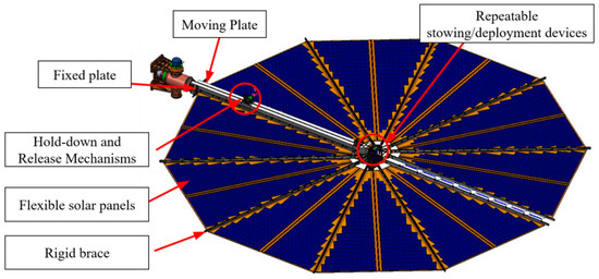
Figure 1.
Fan-shaped flexible solar cell array.
The repeatable stowing/deployment fan-shaped flexible solar array shows remarkable symmetry in its structural design, which runs through the overall layout and key components. The overall layout takes the center axis as the symmetry axis, and the components, such as flexible solar panels and rigid supports, are uniformly distributed along the radial direction to form a complete fan-shaped structure.
The symmetry design of key components is also crucial. Flexible solar panels are the main component of the array, and due to the characteristics of fan-form deployment, individual flexible solar panels are mostly triangular in shape, as shown in Figure 2.
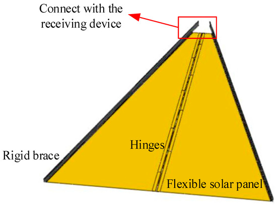
Figure 2.
Schematic diagram of a flexible solar cell module.
A single flexible solar panel is mainly composed of substrate, cell circuit, and buffer foam, and the cell adopts a flexible thin-film solar cell, which is glued with adhesive between cell and substrate, and between substrate and buffer foam. The substrate is a composite material, which reduces its own thermal stress through the design of symmetric stacking. Multiple flexible solar cell panels are interconnected through hinges to form a flexible solar cell module, and the fan-shaped flexible solar cell array adopts a skeleton-type brace to support the flexible solar cell module, forming a symmetric radial structure.
The symmetric stowing/deployment structure design makes the force and trajectory of each component in the process of unfolding or retracting symmetric, ensures the smoothness and coordination of the movement, avoids vibration and impact due to uneven force or movement interference, and thus improves the service life and reliability of the solar cell array. When the solar cell array is unfolded, the array surface is rotated around the center by the spreading and closing mechanism, and each flexible solar cell panel is symmetrically unfolded around the hinge axis, the flexible airfoils are pulled apart sequentially, and the folded flexible airfoils are finally spread into a plane, as shown in Figure 3. The folding process of the fan-shaped flexible wing is the inverse process of the unfolding process. The unfolding process of the solar wing is schematically shown in the figure below.
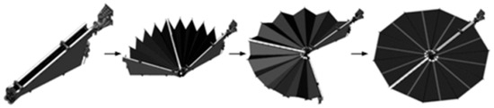
Figure 3.
Schematic diagram of the working principle of the fan-shaped flexible wing.
The weight per unit area of the repeatable stowing/deployment fan-shaped flexible solar arrays is only 50% of that of the traditional rigid arrays [15], and the volume of stowing/deployment is reduced by 20–70% [16], which improves the payload capacity and provides greater flexibility for spacecraft design. Meanwhile, the stowing/deployment mechanism and symmetric design can achieve multiple reliable stowing/deployment, which is suitable for spacecraft requiring multiple orbit changes and docking, such as cargo spacecraft and deep space probes.
3. Methodologies
3.1. Numerical Approach
Solar arrays are subject to harsh high and low temperatures during in-orbit operation; in order to verify the effectiveness of the fan-shaped layout and material stacking of the fan-shaped flexible solar arrays, the thermal distribution of the fan-shaped flexible solar arrays is analyzed by simulation. Patran/Nastran2020 is a mature and widely used simulation and analysis tool in the field of aerospace and aviation, and this paper is based on the Patran/Nastran software. This paper is based on Patran/Nastran software to thermally analyze the fan-shaped flexible wing.
3.1.1. Model Building
Since thermal analysis modeling is very complex and it is not possible to fully consider all the heat transfer factors, necessary simplifying assumptions are made for the model: the component shape is simplified, small-sized components are ignored, and their heat capacities are discounted to adjacent large-sized components; moreover, the surfaces of the components are regarded as diffuse surfaces for thermal radiation.
According to the above assumptions and modeling process, the 3D model is imported into Patran, and appropriate simplification and unit equivalence are carried out to establish the finite element model. The spreading mechanism is simulated by a bush unit, the array is equivalent to a quadrilateral shell unit, and the thermal analysis model is shown in Figure 4.
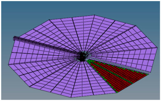
Figure 4.
Thermal analysis model.
3.1.2. Thermal Environment Analysis
The thermal design of a circumlunar orbiting spacecraft requires consideration of the complex thermal environment in which it operates, which includes solar radiation, infrared and albedo heat flows from the Moon and Earth, and the cold background environment of space. The heat balance equation during operation is shown in Figure 5. As a result, the heat balance equation for the outer surface of the fan-flexible wing, which is affected by each component, is
where is direct solar irradiated heat absorbed by a fan-shaped flexible wing, is absorbed infrared radiant heat of the Earth, is the absorbed Earth’s reflected heat, is absorbed heat from lunar albedo, is absorbed heat from the infrared radiation of the Moon, is radiant heat from external surfaces, is exterior shell thermal conductivity, is exterior surface area, is internal and external surface temperatures, and is thickness.
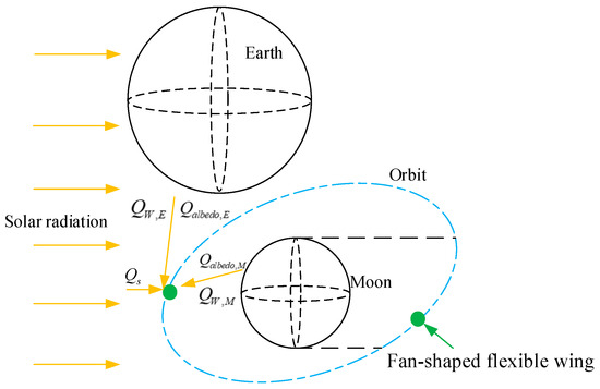
Figure 5.
Thermal balance of fan-shaped flexible wing in space.
The heat of each of these components is analyzed as follows:
(1) Solar irradiation. The solar irradiation heat absorbed by the solar wing is
where is the solar absorptivity on the surface of a fan-shaped flexible wing; is the projected area of the fan flex in the direction of solar incidence of the fan flex; and is the solar constant, approximated as the circumlunar orbital solar constant under the mean Sun–Earth distance ( = 1367 W/m2).
(2) Earth infrared radiation. Since the circumlunar orbit is closer to the Moon than to the Earth, the average distance from the circumlunar orbit to the Earth is approximated to be the Earth–Moon distance, from which the average value of the Earth’s infrared radiation is taken to be
where is the average density of radiant heat flow at the Earth’s surface, is the average radius of the Earth, and is Earth–Moon distance. Since is less than 0.6 W/m2, this value can be ignored.
(3) Earth albedo and lunar surface albedo. Among them, the Earth’s reflection is less compared to the Earth’s infrared radiation, so it can be ignored; the solar absorption ratio of the lunar surface is 0.93, and the reflectivity is 0.07, which has the characteristics of high absorption and low reflection, and diffuse reflection occurs on the surface of the moon dust, so it can be ignored.
(4) Lunar surface radiation, similar to the calculation of the Earth’s infrared radiation, is expressed as
where is the average density of radiative heat flow on the lunar surface, is mean radius of the Moon, and is circumlunar orbital altitude.
(5) The expression for the heat radiated from the surface of the flapping flexible wing is
where is surface emissivity of a flapping flexible wing, and is Stephen Boltzmann’s constant.
With the above analysis, the heat balance equation for the outer surface of the flapping flexible wing can be simplified as
According to reference [8] and the design state, the values of calculated parameters are given in the Table 1.

Table 1.
Summary of calculation parameter values.
3.2. Experiment Design
When a fan-shaped flexible wing operates in space, its external ambient temperature changes continuously with the orbital position, solar irradiation angle, and other factors. This thermal load not only directly affects the material properties but also triggers significant strain responses in subsequent maneuvers (e.g., folding/unfolding) due to structural constraints and thermal expansion effects; therefore, the strain distribution patterns and critical risk regions under the coupling of temperature field and retracting maneuvers are further explored in the following.
In order to test the effectiveness of the fan-shaped flexible array spreading function under the actual high- and low-temperature environments, and to verify the correctness of the thermal matching design analysis on the flexible solar array, this paper proposes a high and low temperature spreading test method for the fan-shaped flexible array, which can simulate the symmetric spreading process of the fan-shaped flexible array under high and low temperature, as well as provide a reference for the further optimization of the material design and the structural design of the flexible solar cell wings.
3.2.1. Experimental Approach
Based on the consideration of ensuring that the flexible solar cell module can be stowed in the high- and low-temperature chamber, this paper designed a set of high- and low-temperature stowage test methods.
The test was carried out in the high- and low-temperature test chamber of the Shanghai Institute of Aerospace System Engineering, which mainly monitors the temperature of the battery board, the strain in the spreading process, and the dynamic spreading screen. The real-time temperature during the test is monitored by temperature sensors, which are placed on the surface of the product; in the strain test, the strain gauges are pasted on the surface of the battery plate and the substrate with patch adhesive, and the dynamic spreading screen is recorded by the high- and low-temperature monitoring camera of CHENWEI TECHNOLOGY. The state of the battery panel to be tested is shown in Figure 6, consisting of two carbon fiber spacers and two flexible solar panels and hinges. The positions of the strain gauge sensors are determined by the preliminary spreading and closing test, and the large deformation areas are mainly concentrated in these three positions, as shown in Figure 6, numbers 1, 2, and 3.
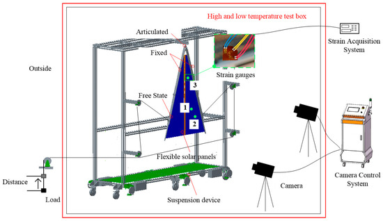
Figure 6.
Schematic diagram of the test status of flexible solar cell modules.
In this paper, two flexible solar panels were connected to each other by hinges and steel wires, and the periphery was fixed by carbon fiber spacers. The upper end of the spacer was connected to the connection tooling on one side by two screws, and the lower end was not constrained. The top end of the connecting tooling was connected to the bracket car through the hanging pin, and at the same time, the connecting tooling was connected to the external Kevlar rope, which was used to hang the load outside the high- and low-temperature chamber through the set of fixed pulleys, so as to realize the spreading and closing action of the flexible solar cell module. Before the test, the hanging shaft and pulley bearings were cleaned with alcohol and fully lubricated with 601EF grease to reduce the resistance.
In order to balance the spreading force of the flexible solar cell module, the hanging force of the flexible solar cell module was balanced with the gravity, as shown in the figure above; the initial angle of the flexible solar cell module was 36°. The hanging load needed to cancel out the gravity component of the connecting tooling and spreader bar in the spreading direction. The load was moved slowly during spreading, and the effectiveness of the spreading function of the flexible solar cell module was monitored by the camera.
3.2.2. Test Content
The product to be tested was placed in a high- and low-temperature chamber and held at the target temperature for 1 h before being spread, by moving the hanging load outside the high- and low-temperature chamber. The design of experimental temperature is shown in Figure 7.
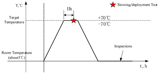
Figure 7.
Test temperature and test time.
Subject to the performance parameters of the monitoring camera, the test temperature should be controlled at ±70 °C.
4. Results and Discussion
4.1. Thermal Analysis Results
The distribution of the array surface at extreme high temperatures is shown in Figure 8, which shows that the extreme high temperatures were mainly concentrated in the center part, spreading outward in a radial pattern, but the maximum temperature difference between the various parts of the array surface was only about 7 °C, and the overall temperature gradient was not large. The maximum temperature of the spar was about 107 °C, which was about 9.3% different from the array surface by 12 °C.
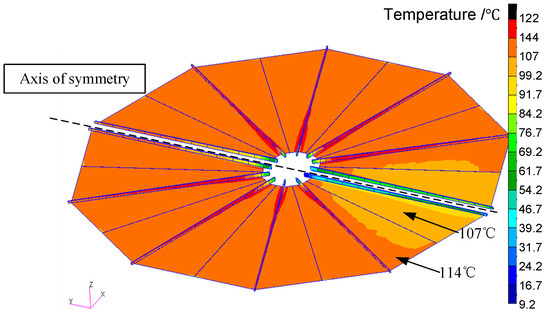
Figure 8.
Extremely high temperature on the front.
The distribution of the array face at extreme low temperatures is shown in Figure 9, where it can be seen that the extreme low temperatures were mainly concentrated on the array face, when the lowest temperature of the spacer was about −141 °C. The overall temperature difference of the array surface was about 11 °C, and the maximum temperature difference was 45 °C, which was concentrated in the connection between the spacer and the array surface.
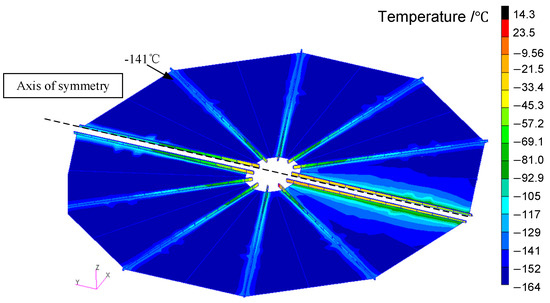
Figure 9.
Extremely low temperature on the front.
The rigid brace as the supporting structure needs to have strong stiffness and strength, while the panel needs to be unfolded and folded, and needs to be a flexible material. Therefore, the design requirements of the two led to different materials: rigid brace for carbon fiber materials, and a panel for composite materials. There were differences in thermal conductivity and hair absorption between the two, so there was a temperature difference between the strut and the front. The overall temperature cloud showed that the array itself had a relatively uniform heat distribution and was symmetrical at extreme high and low temperatures.
4.2. Analysis and Discussion of Test Results
After reaching the target temperature and holding for 1 h, the load was slowly lifted at a constant speed outside the high- and low-temperature chamber to release the gravity component of the spacer and the workpiece in the direction of closing, so that the battery plate was closed by this gravity component. The dynamic picture of the folding process is shown in Figure 10 and Figure 11:
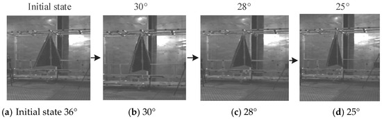
Figure 10.
High temperature +70 °C fold.
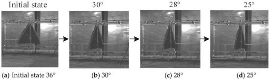
Figure 11.
Low temperature −70 °C fold.
As can be seen from Figure 10 and Figure 11 during the folding process, this rigid-flexible thermal coupling design of rigid spacer and flexible triangular array surface did not appear to be unable to close the panels in high- and low-temperature environments, and at the same time the unfolding process did not appear to be stuck.
Figure 12 shows the strain changes of the flexible solar panel during the folding process in the high- and low-temperature environment. The horizontal coordinate is the number of samples, and the vertical coordinate is the strain.
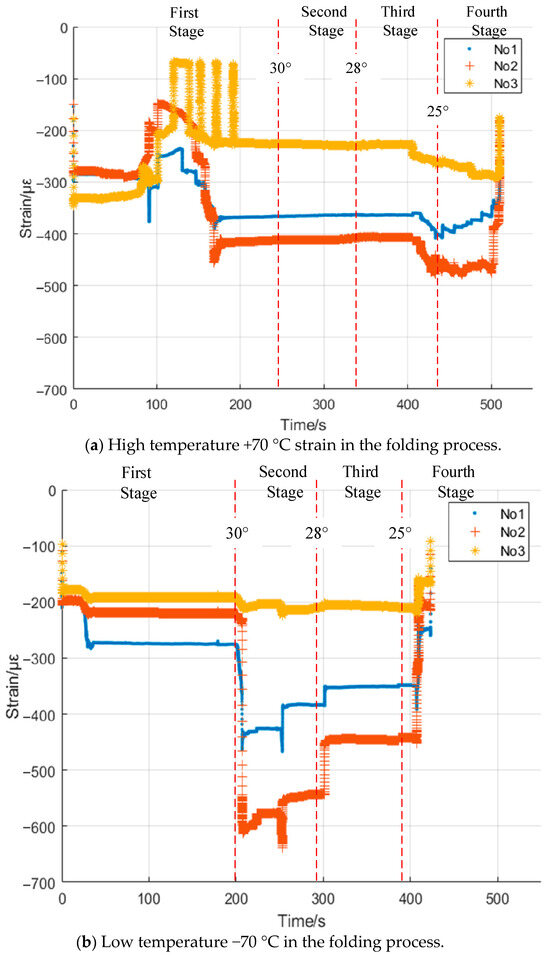
Figure 12.
Strain during the high- and low-temperature folding process.
As can be seen from Figure 12a, in the initial stage of the closing, No. 1 to No. 3 strain size began to decrease, probably because at this time, the gravity component just began to be applied to the panels, offsetting some of the strain, and then the gravity component continued to be applied, and the closing force began to be transmitted to the No. 1 and No. 2 strain gauges, and the size of the strain increased. In the second section (the clamping angle of the tooling changed from about 30° to 28°) of the folding process, the strain of the closing cell was almost unchanged, indicating that the closing force was being transferred here. In the third part of the folding process (the clamping angle of the tooling changes from about 28° to 25°), the closing force was fully transferred, and the strain was 480 με. The closing continued until the panel reached a ready-to-close state (fourth part of the folding process).
According to Figure 12b, in the initial stage of the closing under −70 °C conditions, the strain at all three strain gauge locations began to decrease. This decrease may be attributed to the initial application of the bending moment caused by the tooling force, which started to influence the panels. As the closing process progressed, the bending moment continued to act on the structure, and the closing forces started to be transmitted to strain gauges No. 1 and No. 2, resulting in an increase in strain magnitude. During the second stage of the folding process (when the tooling clamping angle changed from approximately 30° to 28°), the strain at the closing cell exhibited minimal change, indicating that the closing forces were being effectively transferred through the structure without significant deformation. In the third part of the folding process (as the tooling clamping angle reduced from about 28° to 25°), the closing forces were fully transmitted, leading to a noticeable increase in strain, reaching approximately −600 με at strain gauge No. 2. Finally, the closing continued until the panel reached a state ready for complete closure (the fourth part of the folding process), with the strain values stabilizing at certain levels, reflecting the final deformation state of the flexible film under the applied closing forces and tooling clamping conditions at −70 °C.
Comparing Figure 12b low temperature −70 °C with Figure 12a high temperature +70 °C, the biggest difference was that the closing force brought by gravity component was transferred earlier, and the closing force was transferred to the patch in the second stage of the closing process until the panel arrived at the state of closing, and the maximum strain of the cell in this process was 640 με. The reason for the difference in the extreme value of the strain during the low-temperature and high-temperature closing process may lie in that the temperature difference between low temperature and high temperature was 75 °C, which was slightly larger than that of the high temperature of 65 °C. The reason for the difference in the strain extremes between the low- and high-temperature closing process may lie in the fact that the temperature difference between the low temperature and the high temperature was 75 °C, which was slightly larger than that between the high temperature, with the high temperature being 65 °C.
In addition, at −70 °C closing, the strain change of the flexible film was relatively smooth, while at +70 °C closing, the strain change was more complicated, the fluctuation was larger, and the difference of the strain situation of different strain measurement points at different stages was also more obvious. The possible reason for this was that the increase in temperature may reduce the strain hardening rate of the flexible film material, which would lead to a more sensitive response to stress during deformation of the material, which may result in larger deformations at smaller forces, which in turn affects the stability and continuity of the strain, resulting in complex strain fluctuations.
After the test, there was no rupture of the battery cells, nor any obvious crease and deformation of the substrate, and the results of the electrical performance test of the array were normal.
From the repeatable spreading test, it can be seen that the repeatable spreading reliability of the fan-shaped flexible wing was high under the high- and low-temperature environment, and there was no jamming phenomenon in the many times of the spreading process; the strain measurement in the spreading process revealed the safety of the repeatable spreading process, and the maximum strain was only 640 με.
5. Conclusions
In this paper, the thermal response characteristics of flexible solar arrays in extreme thermal environments were investigated, and a high- and low-temperature unfolding test method for sector-shaped flexible solar arrays was firstly proposed. Through the introduction of the rotationally symmetric sector layout, material stacking, and symmetric spreading mechanism, the flexible solar cell array had a better thermal distribution uniformity, the thermal stress concentration was effectively reduced, and new test methods were provided for solving the repeatable stowing/deployment of flexible solar arrays.
The simulation results of the thermal analysis based on Patran/Nastran show that the thermal distribution of the fan-shaped flexible solar array was relatively uniform under extreme high- and low-temperature conditions, and the maximum temperature differences between each part of the array were only about 4 °C and 11 °C, respectively, and the temperature difference between the spacer and the array was within a reasonable range. This verifies the effectiveness of the symmetry design in optimizing the thermal response.
The high- and low-temperature spreading test further verified the reliability and safety of the fan-shaped flexible solar arrays in the actual high- and low-temperature environment. The test results show that the panels can deploy and stow smoothly under high and low temperatures without any jamming or inability to be stowed, and the maximum strain was only 640 με, which was much lower than the yield limit of the material, ensuring the safety of the structure. After the test, there was no rupture of the battery sheet, no obvious deformation of the substrate, and the electrical performance was normal, which proves the reliability and practicability of the design.
This study provides an important reference for the subsequent design and test of flexible solar arrays of other configurations, and it promotes the further development and application of flexible solar array technology in the aerospace field. Subsequently, we will further expand the experimental scale and improve the test equipment to achieve higher temperature conditions.
Author Contributions
L.C.: conceptualization, methodology, formal analysis, investigation, resources, writing—original draft preparation, writing—review and editing, visualization, project administration. A.Z.: conceptualization, validation, writing—review and editing, visualization, supervision. Q.C.: conceptualization, validation, writing—review and editing, visualization. D.W.: validation, writing—review and editing. Z.Y.: validation, writing—review and editing. P.Y.: validation, writing—review and editing. All authors have read and agreed to the published version of the manuscript.
Funding
This research was funded by National Key Research and Development Program of China ‘Additive Manufacturing and Laser Manufacturing’, grant number 2023YFB4606205.
Data Availability Statement
The data used are confidential as the file includes customers’ information.
Conflicts of Interest
The authors declare no conflicts of interest.
References
- Yang, S.; Liang, X.; Shao, L.; Ma, J.; Cheng, Z.; Jiang, X.; Cai, J. Development and Trend of Spacial Flexible Solar Array. Yuhang Xuebao 2023, 44, 1810–1819. [Google Scholar]
- Hoang, B.; White, S.; Spence, B.; Kiefer, S. Commercialization of Deployable Space Systems’ roll-out solar array (ROSA) technology for Space Systems Loral (SSL) solar arrays. In Proceedings of the 2016 IEEE Aerospace Conference, Big Sky, MT, USA, 5–12 March 2016; pp. 1–12. [Google Scholar]
- Yan, Y.; Li, J.; Huang, H.; Wang, C.; Li, P.; Mei, J.; Cheng, B.; Zhang, D. Design and investigation of flexible solar wing: In-plane dynamics. Int. J. Mech. Sci. 2024, 283, 109673. [Google Scholar] [CrossRef]
- Li, J.; Hu, M.; Meng, S.; Zhang, L.; Gao, X.; Zhang, D. Analysis of modal shape and harmonic response of folding mechanism of fan-shaped solar arrays. Hangtian Qi Huanjing Gongcheng 2020, 37, 435–439. [Google Scholar]
- Boulanger, B.; Baudassé, Y.; Guinot, F.; D’abrigeon, L.; Thibaudeau, M.; Heim, M.; Buffe, F.; Rapp, E. Development of Innovative Mechanical Flexible Solar Array Architecture. E3S Web Conf. 2017, 16, 01005. [Google Scholar] [CrossRef]
- Angmo, D.; Yan, S.; Liang, D.; Scully, A.D.; Chesman, A.S.R.; Kellam, M.; Duffy, N.W.; Carter, N.; Chantler, R.; Chen, C.; et al. Toward Rollable Printed Perovskite Solar Cells for Deployment in Low-Earth Orbit Space Applications. ACS Appl. Energy Mater. 2024, 7, 1777–1791. [Google Scholar] [CrossRef]
- Zhang, W.; Zhu, W.; Zhang, S. Deployment Dynamics for a Flexible Solar Array Composed of Composite-Laminated Plates. J. Aerosp. Eng. 2020, 33, 04020071. [Google Scholar] [CrossRef]
- Jones, P.A.; Spence, B.R. Spacecraft solar array technology trends. IEEE Aerosp. Electron. Syst. Mag. 2011, 26, 17–28. [Google Scholar] [CrossRef]
- Murphy, D.; Eskenazi, M.; McEachen, M.; Spink, J. UltraFlex and MegaFlex-Development of highly scalable solar power. In Proceedings of the 2015 IEEE 42nd Photovoltaic Specialist Conference (PVSC), New Orleans, LA, USA, 14–19 June 2015; p. 8. [Google Scholar]
- Hu, M.; Li, W.; Chen, W.; Tian, F.; Zhang, Y. Motion simulation and function test on repeated fold-unfold mechanism of fan-shaped solar array. CJSS 2022, 36, 92–98. [Google Scholar] [CrossRef]
- Yan, B.; Qin, L.; Tao, S.; Fang, G. Development and challenges of large space flexible solar arrays. Space Sol. Power Wirel. Transm. 2025, 2, 33–42. [Google Scholar] [CrossRef]
- Vielma-Quintero, J.C.; Diaz-Segura, E.G.; Vielma, J.C. Influence of the Plan Structural Symmetry on the Non-Linear Seismic Response of Framed Reinforced Concrete Buildings. Symmetry 2024, 16, 370. [Google Scholar] [CrossRef]
- Vlase, S.; Öchsner, A.; Marin, M. Dynamic properties of the structures with three level of symmetry. Contin. Mech. Thermodyn. 2025, 37, 23. [Google Scholar] [CrossRef]
- Meng, X.; Cheng, K.; Zhao, Q.; Chen, X. Hierarchical Hypervapotron Structure Integrated with Microchannels for Advancement of Thermohydraulic Performance. Symmetry 2024, 16, 1089. [Google Scholar] [CrossRef]
- Zhou, Z.; Wu, Y.; Wang, J.; Liu, Y.; Yan, Z.; Hang, C. Development and Trend of Circular Solar Array. Spacecr. Eng. 2015, 6, 116–122. [Google Scholar]
- Liu, J.; Yin, X.; Song, X.; Xiao, Y. Future solar array scenario for lunar research station. Dianyuan Jishu 2024, 48, 416–420. [Google Scholar]
Disclaimer/Publisher’s Note: The statements, opinions and data contained in all publications are solely those of the individual author(s) and contributor(s) and not of MDPI and/or the editor(s). MDPI and/or the editor(s) disclaim responsibility for any injury to people or property resulting from any ideas, methods, instructions or products referred to in the content. |
© 2025 by the authors. Licensee MDPI, Basel, Switzerland. This article is an open access article distributed under the terms and conditions of the Creative Commons Attribution (CC BY) license (https://creativecommons.org/licenses/by/4.0/).