
Research on the Stability Control of Four-Wheel Steering for Distributed Drive Electric Vehicles


Abstract
1. Introduction
1.1. Motivation and Technical Challenge
1.2. Literature Review
1.3. Main Contributions
- (1)
- Based on the design of constant yaw rate gain VSR strategy, the reference front wheel angle is obtained, which solves the problem that the traditional constant steering ratio cannot dynamically adjust the transmission ratio according to vehicle speed and driver input angle. It achieves the sensitivity of low-speed steering and the stability of high-speed steering, and improves system adaptability;
- (2)
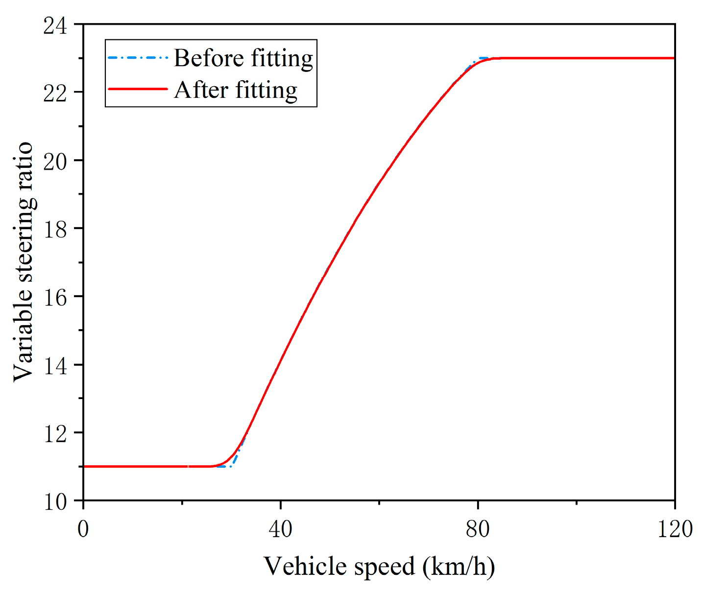
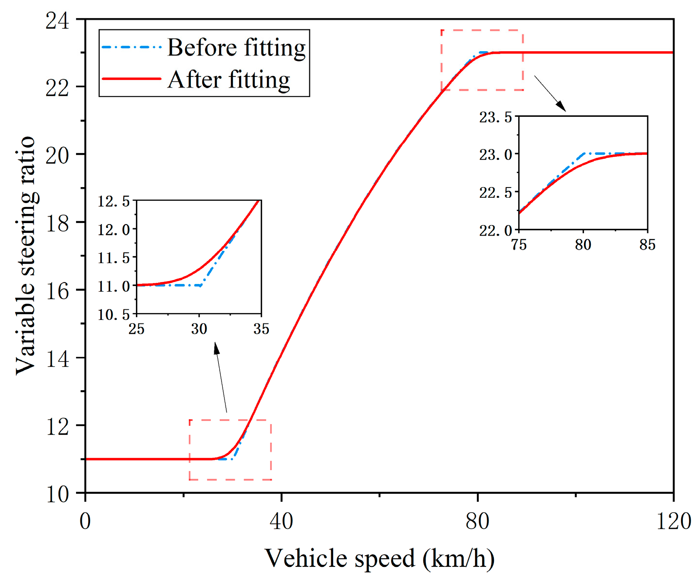
- To reduce steering fluctuations, the VSR strategy is combined with a cubic quasi-uniform B-spline curve fitting method to achieve the purpose of locally optimizing the VSR curve, thereby improving the steering performance caused by non-smooth curves at critical speeds;
- (3)
- To solve the problems of chattering and slow convergence speed in traditional SMC, a 4WS controller based on the FAST algorithm is designed to calculate the additional rear wheel angle. This algorithm does not require prior knowledge of the system uncertainty boundary, taking into account system anti-interference, and has relatively fast convergence speed and control accuracy, thereby enhancing the handling stability of four-wheel steering at different speeds.
1.4. Paper Organization
2. Vehicle Dynamic Model
2.1. Vehicle Lateral Dynamics Model
2.2. Ideal Reference Model
3. Variable Steering Ratio Curve Design
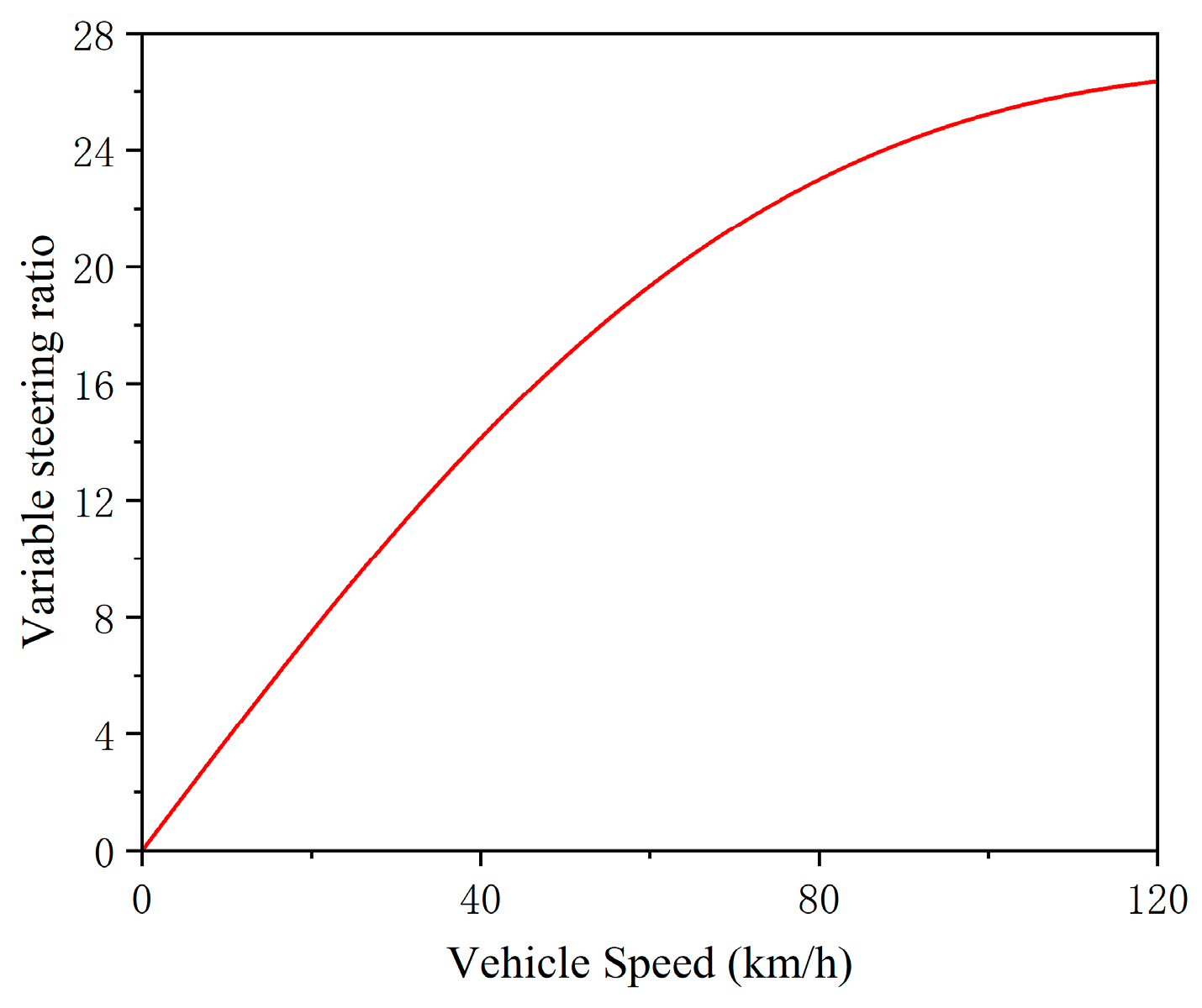
3.1. Constant Yaw Rate Gain
3.2. Ideal VSR Curve
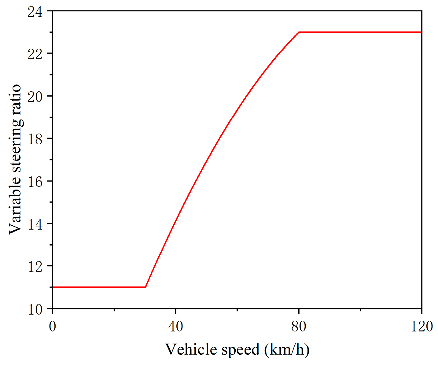
3.3. VSR Strategy Design and Curve Fitting
4. WS Controller Design
4.1. FAST Sliding Mode Control Algorithm
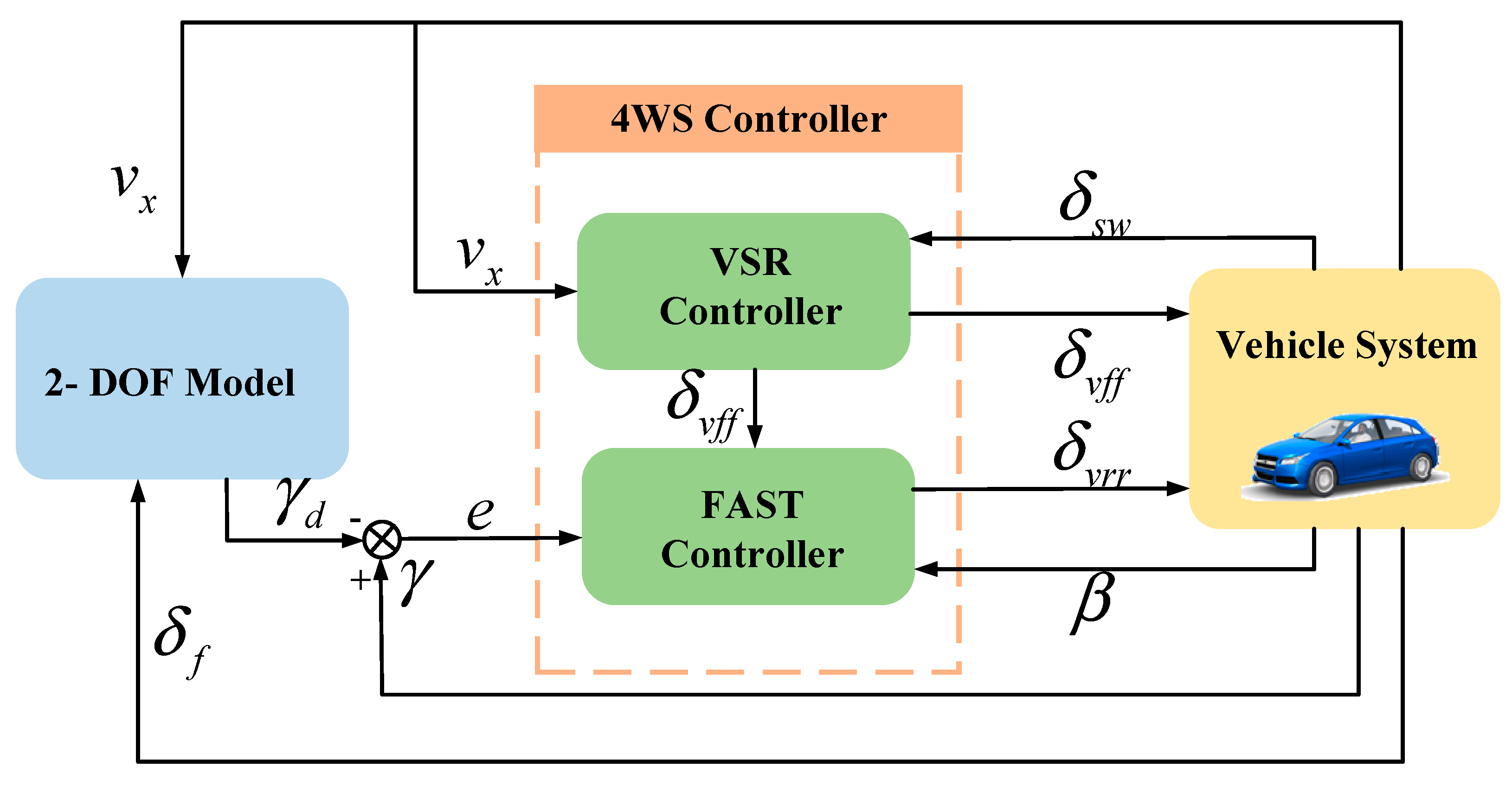
4.2. Design of 4WS Controller Based on VSR-FAST
4.3. Stability Proof of FAST Controller
- (1)
- is a positive definite;
- (2)
- The existence of positive real numbers , , , and an open neighborhood , containing the origin, makes the equation hold:
5. Simulation Results’ Analysis
5.1. Vehicle Parameters
5.2. VSR Fitting Results’ Analysis
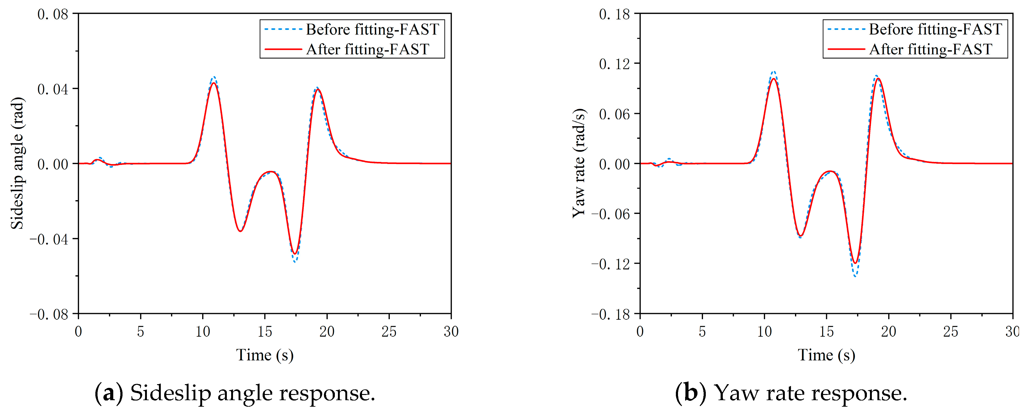
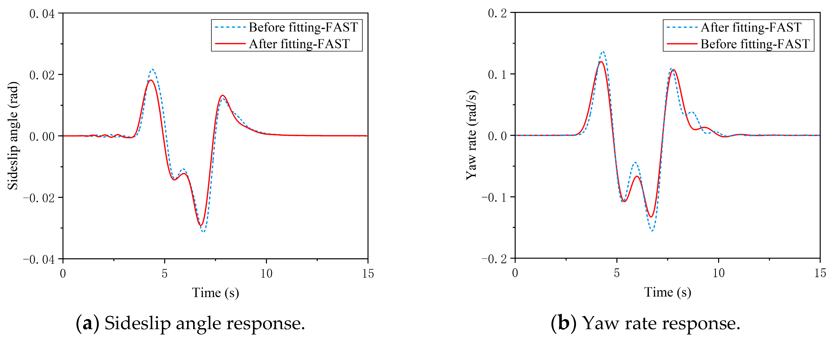
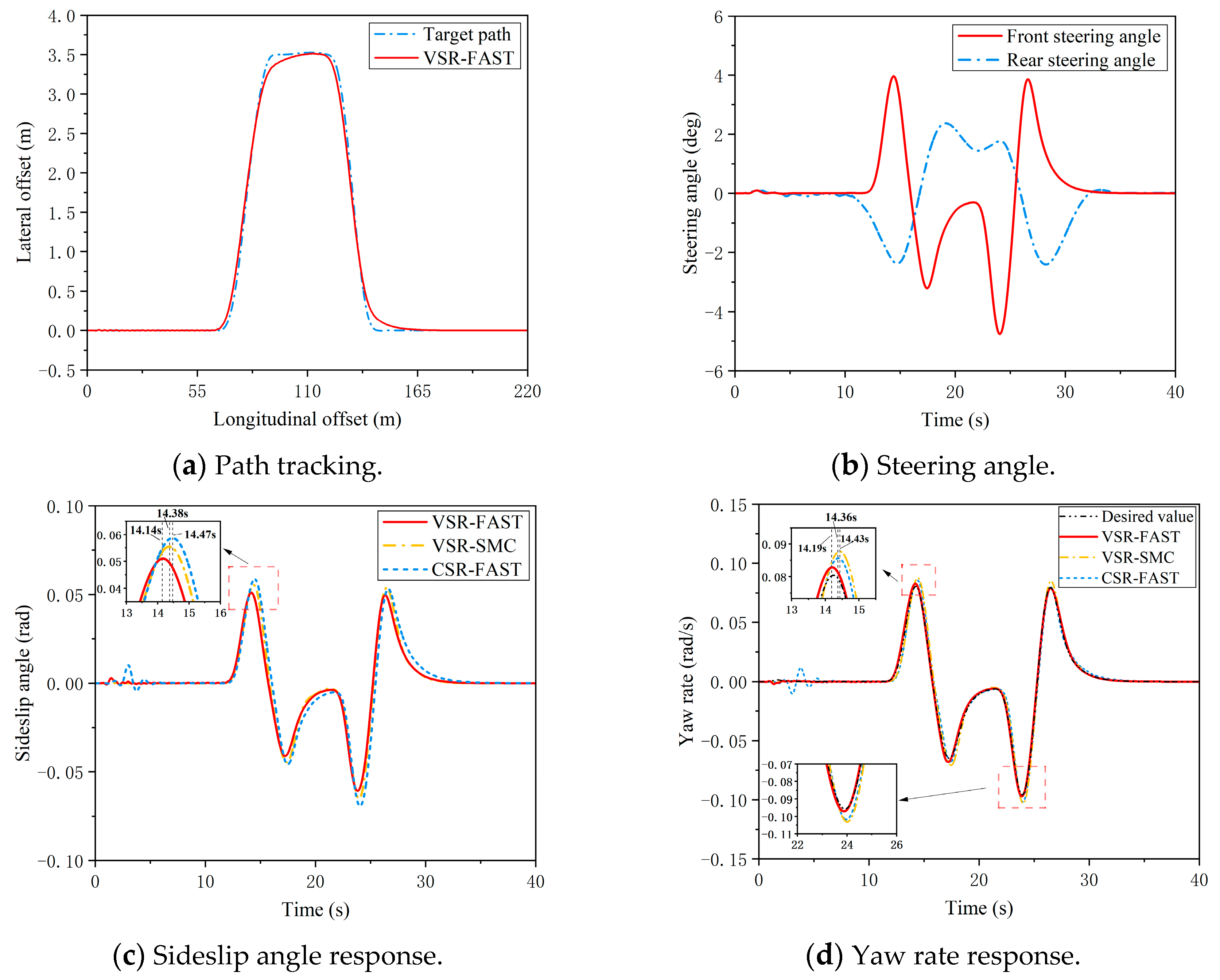
5.3. VSR-FAST Controller Simulation
- (1)
- Low speed
- (2)
- Medium speed
- (3)
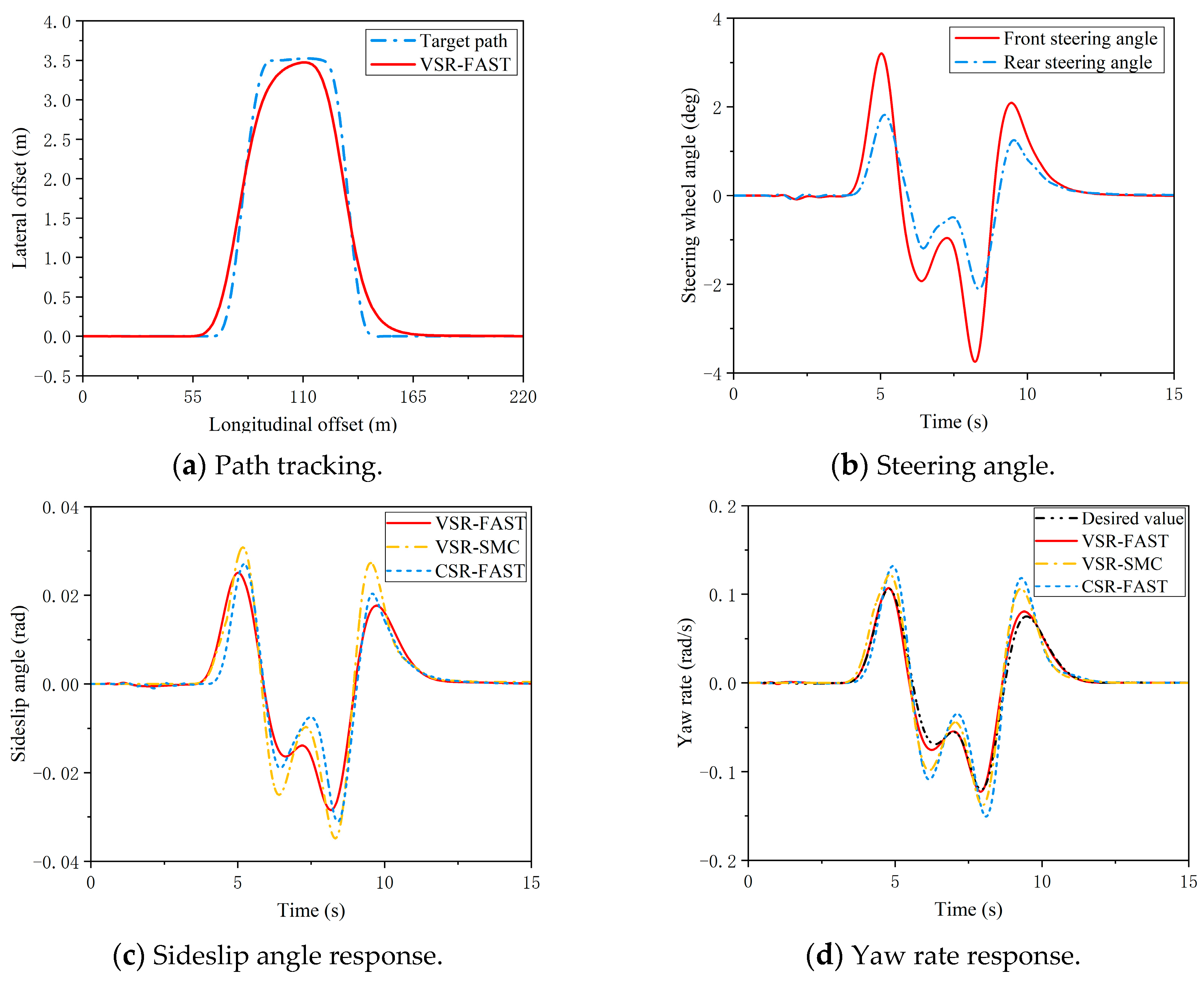
- High speed
6. Conclusions
- (1)
- The VSR curve after cubic quasi-uniform B-spline fitting reduces the steering fluctuation and improves the adverse influence of sudden change in SR in the critical speed region on the steering stability;
- (2)
- Compared to CSR, the VSR enhances the low-speed agility and high-speed stability of 4WS, improving adaptability to diverse conditions. The FAST algorithm, compared to SMC, effectively mitigates chattering, boosts disturbance rejection, and enhances convergence speed and precision away from equilibrium. The VSR-FAST controller efficiently handles double-lane changes at various speeds, tracking the desired sideslip angle and yaw rate effectively. It achieves superior path tracking, high control precision, strong disturbance rejection, adaptability, and rapid convergence, thereby enhancing 4WS maneuverability and stability.
Author Contributions
Funding
Data Availability Statement
Acknowledgments
Conflicts of Interest
Abbreviations
| 4WS | Four-Wheel Steering |
| VSR | Variable Steering Ratio |
| FAST | Fast Adaptive Super-Twisting |
| DDEVs | Distributed Drive Electric Vehicles |
| AFS | Active Front Steering |
| PID | Proportional–Integral–Derivative |
| LQR | Linear Quadratic Regulator |
| SMC | Sliding Mode Control |
| ST | Super-Twisting |
| CG | Center of Gravity |
| 2-DOF | Two-Degree-of-Freedom |
| CSR | Constant Steering Ratio |
References
- Tang, X.; Chen, J.; Gao, B.; Yang, K.; Hu, S.; Li, K. Deep reinforcement learning-based integrated control of hybrid electric vehicles driven by high definition map in cloud control system. J. Mech. Eng. 2022, 58, 163–177. [Google Scholar] [CrossRef]
- Chen, Q.; Xiong, Z.; Hu, Y.; Huang, L.; Liu, Q.; You, D. AFS control system research of distributed drive electric vehicles by adaptive super-twisting sliding mode control. Trans. Inst. Meas. Control 2024, 46, 1388–1396. [Google Scholar] [CrossRef]
- Chang, X.; Zhang, H.; Yan, S.; Hu, S.; Meng, Y. Analysis and roll prevention control for distributed drive electric vehicles. World Electr. Veh. J. 2022, 13, 210. [Google Scholar] [CrossRef]
- Xiao, X.; Zhang, Z.; Huang, M.; Guan, L.; Song, Y.; Zeng, J. A Dual-Layer Control System for Steering Stability of Distributed-Drive Electric Vehicle. World Electr. Veh. J. 2024, 15, 515. [Google Scholar] [CrossRef]
- Liu, H.; Liu, C.; Han, L.; Xiang, C. Handling and stability integrated control of AFS and DYC for distributed drive electric vehicles based on risk assessment and prediction. IEEE Trans. Intell. Transp. Syst. 2022, 23, 23148–23163. [Google Scholar] [CrossRef]
- Tourajizadeh, H.; Sarvari, M.; Afshari, S. Path planning and optimal control of a 4WS vehicle using calculus of variations. Acta Mech. Sin. 2024, 40, 523217. [Google Scholar] [CrossRef]
- Park, H.; Kim, M. Development of a Path Tracker Based on a 4WS Vehicle for Low-Speed Automated Driving Systems. Appl. Sci. 2025, 15, 3043. [Google Scholar] [CrossRef]
- Zhu, S.; Wei, B.; Liu, D.; Chen, H.; Huang, X.; Zheng, Y.; Wei, W. A dynamics coordinated control system for 4WD-4WS electric vehicles. Electronics 2022, 11, 3731. [Google Scholar] [CrossRef]
- Zhu, J.; Feng, T.; Kang, S.; Chen, D.; Ni, X.; Wang, L. Design and Simulation of Steering Control Strategy for Four-Wheel Steering Hillside Tractor. Agriculture 2024, 14, 2238. [Google Scholar] [CrossRef]
- Yu, M.; Cheng, C.; Zhou, P.; Chen, Z.M. 4WIS research based on feedforward-fuzzy PID feedback combined control. J. Chongqing Univ. Technol. Nat. Sci. 2019, 33, 207–213. [Google Scholar] [CrossRef]
- Luo, Y.; Zhou, T.; Xu, X. Time-varying LQR control of four-wheel steering-drive vehicle-based on genetic algorithm. J. South China Univ. Technol. Nat. Sci. 2021, 49, 114–122. [Google Scholar] [CrossRef]
- Zhou, B.; Fan, L.; Lv, X. Improved Variable Ratio Curve Design for Active Front Wheel Steering System. Chin. J. Mech. Eng. 2014, 25, 2813–2818. [Google Scholar]
- Nogami, N.; Ozu, Y.; Morita, Y.; Suzuki, Y.; Takahashi, T. Pure Pursuit Method with Variable Ratio of Front-and Rear-wheel Steering Angles for Four-wheel Independent Steering Vehicles. In Proceedings of the International Conference on Control, Automation and Systems, Jeju, Republic of Korea, 29 October–1 November 2024. [Google Scholar] [CrossRef]
- Kang, L.; Xia, Z. Design and Study of Variable Steering Ratio Curve of Active Front Wheel Steering. J. Chongqing Univ. Technol. Nat. Sci. 2015, 29, 23–28. [Google Scholar] [CrossRef]
- Li, X.; Zhang, J. Design of AFS variable steering ratio considering road adhesion coefficient and vehicle speed. J. Automot. Saf. Energy 2020, 11, 329. [Google Scholar] [CrossRef]
- Li, Z.; Shan, C.; Na, S.; Xi, W. Design and Motor Control Research of Variable Transmission Ratio for Active Steering Systems. J. Chongqing Univ. Technol. Nat. Sci. 2018, 32, 19–26. [Google Scholar] [CrossRef]
- Chen, Z.; Zhong, C.; Li, H. Particle swarm optimization for steer-by-wire variable angle ratio fuzzy controller design. J. Chongqing Univ. Technol. Nat. Sci. 2023, 36, 41–49. [Google Scholar] [CrossRef]
- Zhao, B.; Fan, X.; Qi, G. Variable transmission ratio and active steering control for steer-by-wire steering. Int. J. Veh. Syst. Model. Test. 2022, 16, 290–312. [Google Scholar] [CrossRef]
- Liu, Z.; Xu, X.; Xie, J.; Wang, F.; Su, P. Variable transmission ratio design of a steer-by-wire system for intelligent vehicles. Proc. Inst. Mech. Eng. Part C J. Mech. Eng. Sci. 2022, 236, 9341–9353. [Google Scholar] [CrossRef]
- Zhou, L.; Li, Z.; Yang, H.; Tan, C. Integral predictive sliding mode control for high-speed trains: A dynamic linearization and input constraint-based data-driven scheme. Control. Eng. Pract. 2025, 154, 106139. [Google Scholar] [CrossRef]
- Lu, C.; Yuan, J.; Zha, G. Sliding mode integrated control for vehicle systems based on AFS and DYC. Math. Probl. Eng. 2020, 2020, 8826630. [Google Scholar] [CrossRef]
- Changoski, V.; Gjurkov, I.; Jordanoska, V. Improving vehicle dynamics employing individual and coordinated sliding mode control in vehicle stability, active front wheel steering and active rear wheel steering systems in co-simulation environment. IOP Conf. Ser. Mater. Sci. Eng. 2022, 1271, 1–13. [Google Scholar] [CrossRef]
- Dai, P.; Katupitiya, J. Force control for path following of a 4WS4WD vehicle by the integration of PSO and SMC. Veh. Syst. Dyn. 2018, 56, 1682–1716. [Google Scholar] [CrossRef]
- Dang, D. A Fuzzy Sliding Mode Four-wheel Steering Control Method on Exponential Approach Rate. Automob. Appl. Tech. 2022, 47, 21–25. [Google Scholar] [CrossRef]
- Khanke, T.; Chaudhari, S.; Phadke, S.; Shendge, P. Yaw stability of 4ws with variable steering ratio strategy using inertial delay control based sliding mode control. In Proceedings of the International Conference on Communication and Electronics Systems, Coimbatore, India, 17–19 July 2019. [Google Scholar] [CrossRef]
- Zhou, Z.; Zhang, J.; Yin, X. Adaptive Sliding Mode Control for Yaw Stability of Four-Wheel Independent-Drive EV Based on the Phase Plane. World Electr. Veh. J. 2023, 14, 116. [Google Scholar] [CrossRef]
- Tian, J.; Ding, J.; Tai, Y.; Chen, N. Hierarchical control of nonlinear active four-wheel-steering vehicles. Energies 2018, 11, 2930. [Google Scholar] [CrossRef]
- Tan, L.; Yu, S.; Guo, Y.; Chen, H. Sliding-mode control of four wheel steering systems. In Proceedings of the International Conference on Mechatronics and Automation, Takamatsu, Japan, 6–9 August 2017. [Google Scholar] [CrossRef]
- Zhang, C.; Liu, H.; Dang, M. Robust shared control for four-wheel steering considering driving comfort and vehicle stability. World Electr. Veh. J. 2023, 14, 283. [Google Scholar] [CrossRef]
- Levant, A. Sliding order and sliding accuracy in sliding mode control. Int. J. Control 1993, 58, 1247–1263. [Google Scholar] [CrossRef]
- Liu, L.; Ding, S.; Li, S. A survey for high-order sliding mode control theory. Control Theory Appl. 2022, 39, 2193–2201. [Google Scholar]
- Dan, N.; Yuan, Y.H.; Feng, J. Sliding mode control of PMSM based on fast STA and disturbance observer. Comp. Simul. 2020, 37, 173–178. [Google Scholar]
- Tu, Y.; Wang, Y.; Wu, Z.; Luo, F. Decoupled Nonsingular Fast Terminal Sliding Mode Control Based on Super Twisted Algorithm. Control Eng. China 2020, 27, 271–277. [Google Scholar] [CrossRef]
- Hu, C.; Qin, Y.; Cao, H.; Song, X.; Jiang, K.; Rath, J.J.; Wei, C. Lane keeping of autonomous vehicles based on differential steering with adaptive multivariable super-twisting control. Mech. Syst. Signal Process. 2019, 125, 330–346. [Google Scholar] [CrossRef]
- Men, L. Simulation Analysis of Vehicle Four-Wheel Steering Control. Int. J. Sci. Adv. 2023, 4, 259–264. [Google Scholar] [CrossRef]
- Ji, P.; Han, F.; Zhao, Y. Stability Study of Distributed Drive Vehicles Based on Estimation of Road Adhesion Coefficient and Multi-Parameter Control. World Electr. Veh. J. 2025, 16, 38. [Google Scholar] [CrossRef]
- Wu, X.; Li, W. Variable steering ratio control of steer-by-wire vehicle to improve handling performance. Proc. Inst. Mech. Eng. Part D J. Automob. Eng. 2020, 234, 774–782. [Google Scholar] [CrossRef]
- Lin, Z.; Chen, T.; Jiang, Y.; Wang, H.; Lin, S.; Zhu, M. B-Spline-Based Curve Fitting to Cam Pitch Curve Using Reinforcement Learning. Intell. Autom. Soft Comput. 2023, 36, 2145. [Google Scholar] [CrossRef]
- Liu, C.; Yang, S.; Wang, L.; Zhang, K. Guidance law based on fast adaptive super-twisting algorithm. J. Beijing Univ. Aeronaut. Astronaut. 2019, 45, 1388–1397. [Google Scholar] [CrossRef]
- Wang, Z. Adaptive smooth second-order sliding mode control method with application to missile guidance. Trans. Inst. Meas. Control 2017, 39, 848–860. [Google Scholar] [CrossRef]


| Symbol | Parameter | Value/Unit |
|---|---|---|
| Vehicle mass | 1412/kg | |
| Distance from CG to front axle | 1.015/m | |
| Distance from CG to rear axle | 1.895/m | |
| Wheelbase | 2.91/m | |
| Yaw moment of inertia | 1536.7/kg·m2 | |
| Center of gravity | 0.54/m | |
| Wheel radius | 0.31/m |
Disclaimer/Publisher’s Note: The statements, opinions and data contained in all publications are solely those of the individual author(s) and contributor(s) and not of MDPI and/or the editor(s). MDPI and/or the editor(s) disclaim responsibility for any injury to people or property resulting from any ideas, methods, instructions or products referred to in the content. |
© 2025 by the authors. Licensee MDPI, Basel, Switzerland. This article is an open access article distributed under the terms and conditions of the Creative Commons Attribution (CC BY) license (https://creativecommons.org/licenses/by/4.0/).
Share and Cite
Pang, H.; Chen, Q.; Cai, Y.; Gong, C.; Jiang, Z. Research on the Stability Control of Four-Wheel Steering for Distributed Drive Electric Vehicles. Symmetry 2025, 17, 732. https://doi.org/10.3390/sym17050732
Pang H, Chen Q, Cai Y, Gong C, Jiang Z. Research on the Stability Control of Four-Wheel Steering for Distributed Drive Electric Vehicles. Symmetry. 2025; 17(5):732. https://doi.org/10.3390/sym17050732
Chicago/Turabian StylePang, Hongyu, Qiping Chen, Yuanhao Cai, Chunhui Gong, and Zhiqiang Jiang. 2025. "Research on the Stability Control of Four-Wheel Steering for Distributed Drive Electric Vehicles" Symmetry 17, no. 5: 732. https://doi.org/10.3390/sym17050732
APA StylePang, H., Chen, Q., Cai, Y., Gong, C., & Jiang, Z. (2025). Research on the Stability Control of Four-Wheel Steering for Distributed Drive Electric Vehicles. Symmetry, 17(5), 732. https://doi.org/10.3390/sym17050732