
Symmetry-Aware Hybrid Verification for Complex Building Information Systems


Abstract
1. Introduction
2. Related Work and Background
2.1. Related Work
- (1)
- Building information modeling technology
- BIM mainly encapsulates static information about building geometric data, spatial location, relational modeling, quality attributes, etc. [2]. BIM has a relatively mature conceptual framework.
- GISs primarily describe aspects of geospatial data such as geometric primitives (from 0 to 3 dimensions), coordinate reference systems, and topology. However, the information is usually not comprehensive and detailed enough due to the lack of fine-grained geometric and semantic information [16]. GIS technologies are usually integrated with BIM and their conceptual frameworks are relatively mature.
- DT consists of three main components: the physical world, virtual representation and virtual–real interaction, and virtual representation and virtual–real exchange interconnection [17]. However, digital twins have almost no unified information model.
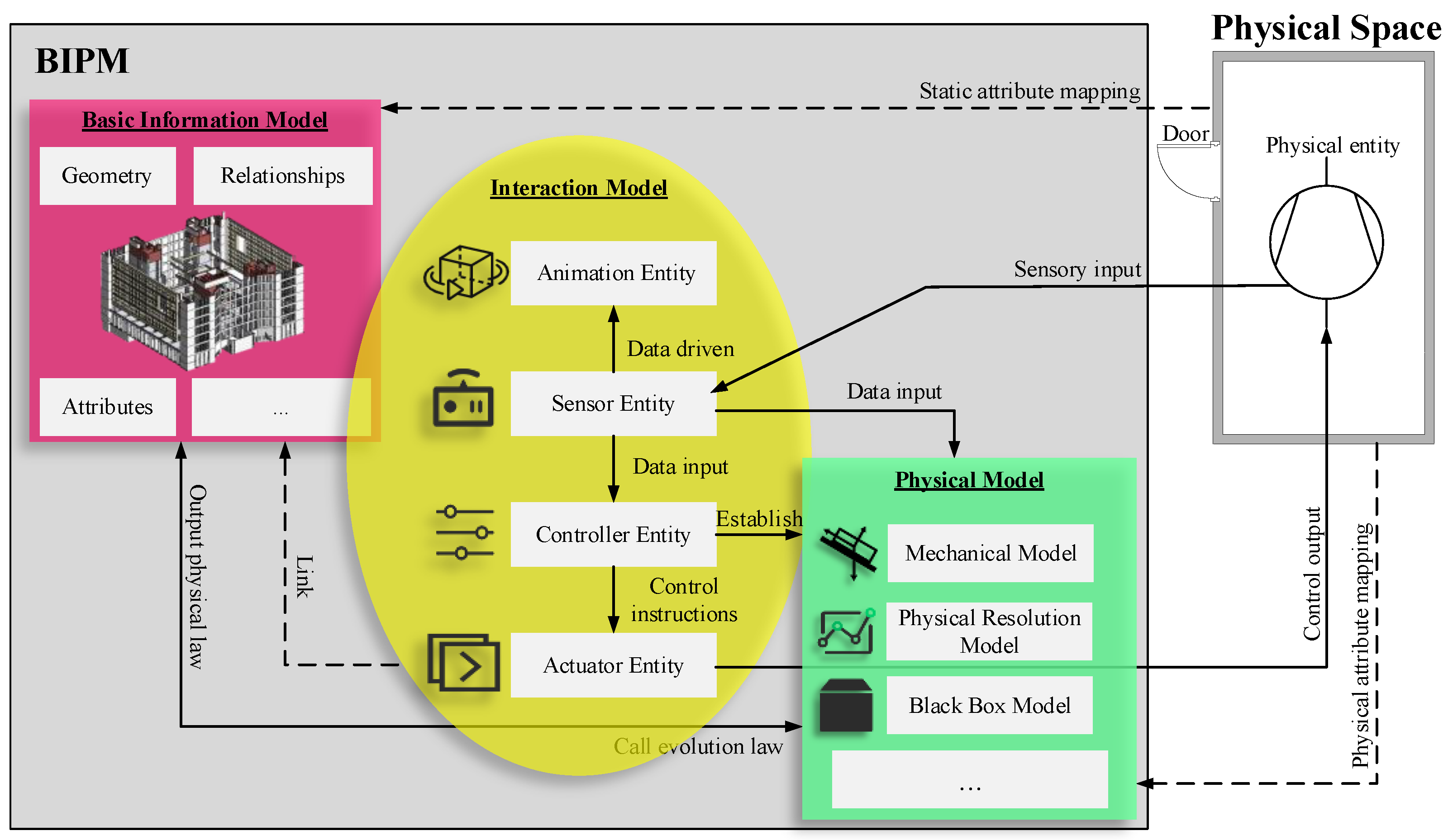
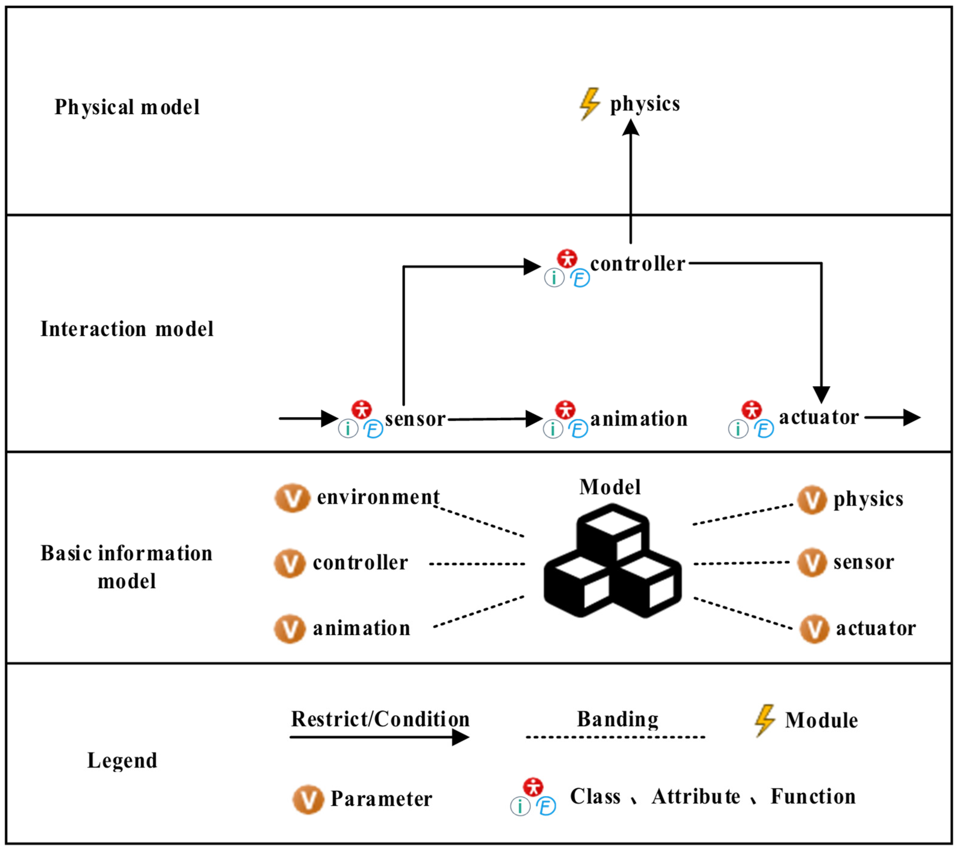
- BIPM consists of three main sub-models: The basic information model, the interaction model, and the physical model. Compared with existing static BIM technologies, BIPM can dynamically interact with external entities and map the intrinsic mechanism in full fidelity [10]. In addition, BIPM integrates the information and physical domains, which requires rigorous simulation verification to ensure the credibility of the model.
- (2)
- AnyLogic software technology
- (3)
- Model detection techniques
2.2. Background
2.3. Innovative Contribution
- This paper proposes a novel framework that combines TA, UML, and AnyLogic simulation software to model and validate complex building information systems. This framework integrates formal verification with dynamic visualization, ensuring both logical correctness and practical applicability.
- By transforming the behavioral model of the BIPM into a TAN, this study enables rigorous formal verification of its dynamic interactions and physical mechanisms. This ensures the reliability and logical consistency of the BIPM, addressing a critical gap in traditional validation methods.
- This paper maps the structural model of the BIPM into a visual simulation model using AnyLogic, allowing for real-time, dynamic visualization of the building system’s behavior. This enhances the interpretability of the model and provides stakeholders with an intuitive platform to analyze system performance under various operational conditions.
- Using an air conditioning system as a case study, this study demonstrates the feasibility and effectiveness of the proposed method. This practical validation highlights the method’s potential for broader use in complex building systems.
3. Methodology
- Topological symmetry: Establish the visualization model of the building information system. Based on the established building information system and the cropped UML model, construct a building information system class diagram to describe the structural characteristics of the building information system, and construct the building information system sequence diagram to portray the behavioral characteristics of the building information system.
- Behavioral isomorphism symmetry: Convert the building information system visualized models into formal models. Define a model transformation algorithm that converts visualized building information system sequence diagrams into a network of temporal automata that are exchanged for a formal model of the building information system formal model.
- Temporal symmetry: Define the building information system’s formal validation criteria to verify the reliability of the above model. Describe the nature of the building information system using temporal logic to verify the building information system’s trustworthiness.
- Dynamic behavioral symmetry: Convert building information system visual models into simulation models. Map visual building information system class diagrams to AnyLogic-based simulation models to demonstrate physical mechanisms with dynamic visualization in building information systems.

4. BIPM Visual Modeling Based on UML Extension
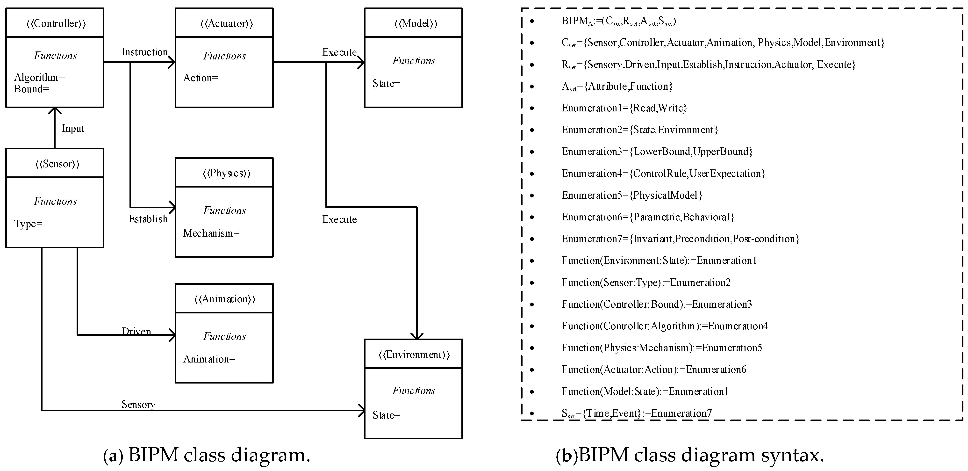
4.1. BIPM Class Diagram
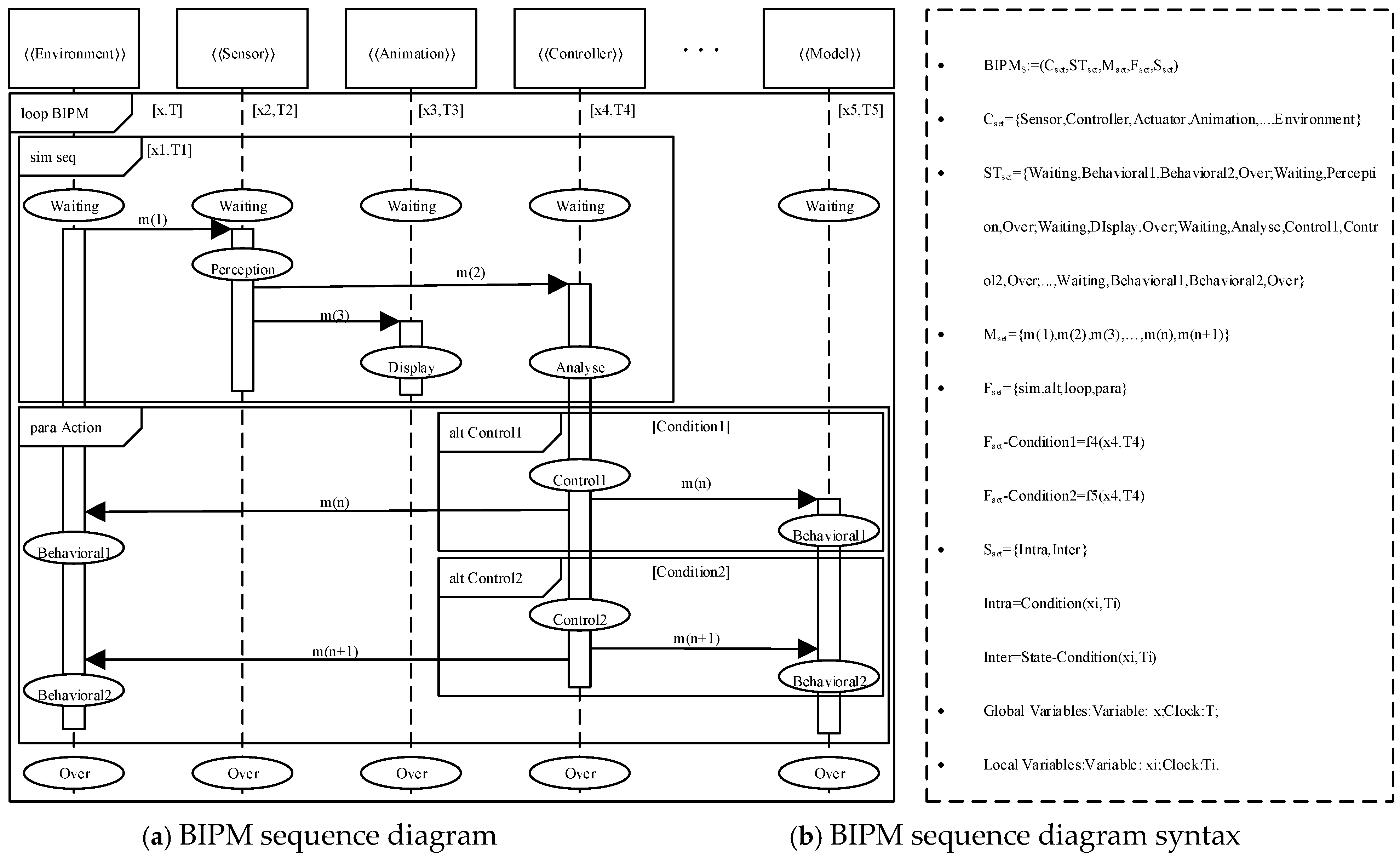
4.2. BIPM Sequence Diagram
5. BIPM Conversion
5.1. Conversion of BIPM’s UML Model to TA Model
- The BIPM sequence diagram can be mapped as a TAN. Cset and state changes during the lifecycle can be inscribed as a TA.
- The state (State) of a BIPM sequence diagram can be mapped to a position (Location) in a temporal automaton. The set of states of the vertical axis of each object in the BIPMS (s∈STset) corresponds to the set of TA positions of each automaton (l∈L), where the initial state of the vertical axis of the BIPMS corresponds to the initial position l0 of the TA.
- The message of the BIPM sequence diagram maps to the channel (Chan) of the TA. Each message of the BIPMS (m∈Mset) corresponds to a pair of transmit and receive events A = ({a!|a∈Chan}∪{a?|a∈Chan}) of the TA.
- The constraint Sset of a BIPM sequence diagram corresponds to the constraint S of TA. Here, the inter-state constraint inter and the fragment constraint Fset (condition) correspond to the constraint S on the side E of TA, and the intra-state intra constraint intra corresponds to the position invariant, Invariant, of TA.
- The variables in BIPM correspond to the data variable Var and the clock variable Clock in TAN.
| Algorithm 1. The conversion algorithm from the BIPM sequence diagram to the TAN | |
| 1 | //Input: BIPM Sequence Diagram; |
| 2 | //Output: Timed Automata Network. |
| 3 | Begin |
| 4 | System Declaration←Variables; |
| 5 | Channel Declaration←Mset; |
| 6 | i = 1, j = 1; |
| 7 | for i ≤ Num(Cset) |
| 8 | {t(i)∈Template←Ci ∈Cset; |
| 9 | Template Declaration(i)←Local Variable(i); |
| 10 | for j ≤ Num(STset (Ci)) |
| 11 | { Location(j)∈t(i)←STset (j)∈STset (Ci); |
| 12 | Location(j).Invariant∈←State-Invariant(i,j);} |
| 13 | (a! or a?)∈t(i)←m∈Mset; |
| 14 | t(i).guard←State-Constraint; |
| 15 | t(i).guard←Fset -Condition(part); } |
| 16 | Model Declaration←Cset; |
| 17 | End |
5.2. Mapping of BIPM Class Diagram to AnyLogic Simulation Model
- A BIPM class diagram can be mapped to an AnyLogic simulation model, whose lifecycle state changes can be animated.
- A BIPM class Cset in a BIPM class diagram can be mapped to a corresponding object class, component, or simulation environment in AnyLogic.
- The Aset attribute set in the BIPM class diagram can be mapped to the attributes or methods of the corresponding object class in AnyLogic, where Attribute can be mapped to the attributes in the object class for describing the characteristics of the object, and Function can be mapped to the methods or functions in the object class for defining the behaviors or operations of the object.
- Sset in the BIPM class diagram can be mapped to the corresponding constraints or limitations in AnyLogic, where Time is mapped to a temporal constraint or condition, and the Event is represented as the relevant trigger condition in the simulation.
6. Case Study
6.1. UML Modeling of Air Conditioning BIPM
- (1)
- Air conditioner BIPM class diagram
- (2)
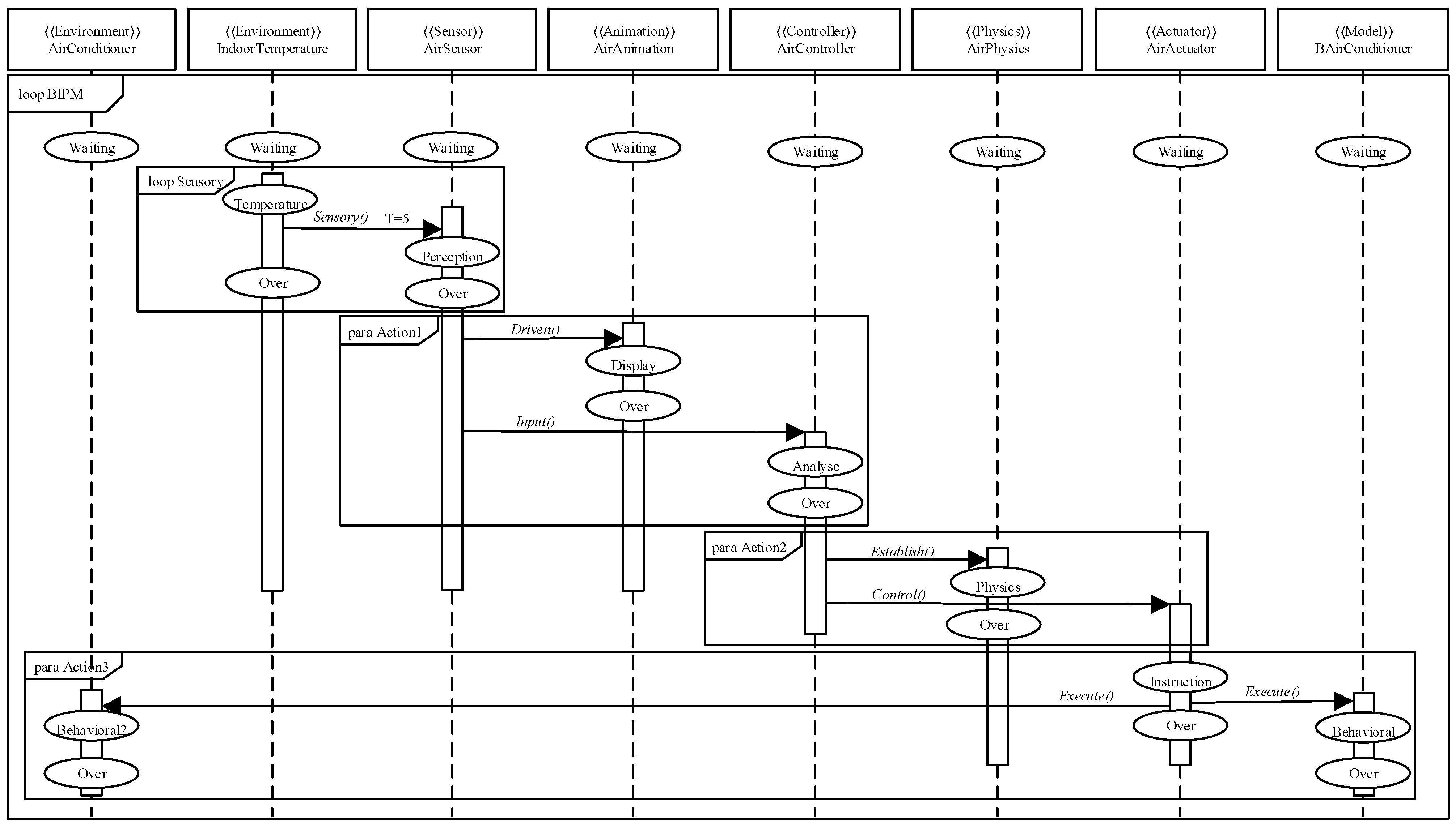
- Air conditioner BIPM sequence diagram
6.2. Formal Validation of Air Conditioning BIPM
- (1)
- Conversion of UML models of air-conditioned BIPM into TA model
- (a)
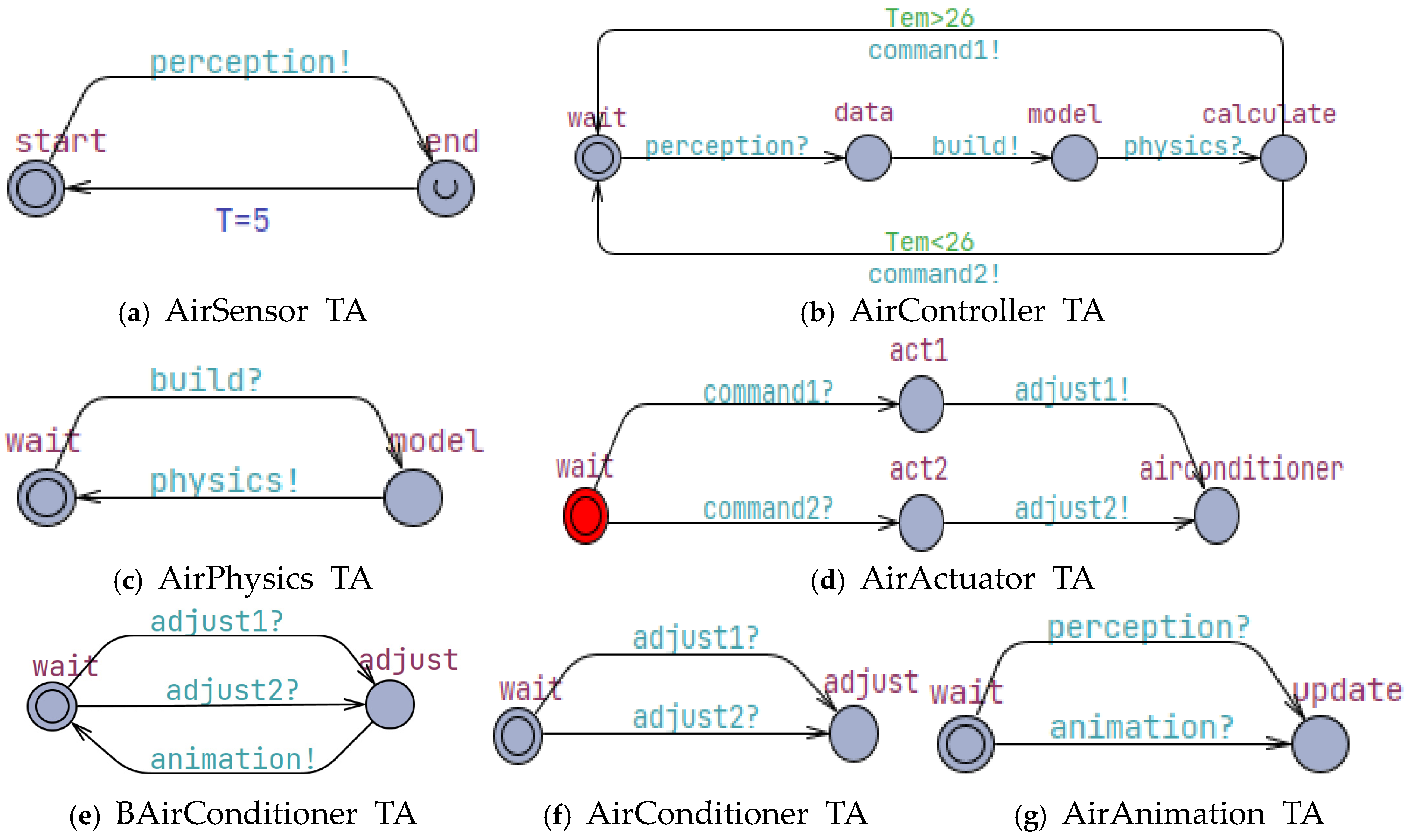
- AirSensor TA. The sensor in the air-conditioned BIPM periodically senses the real-time indoor temperature and sends the sensed data out through the channel perception!, as shown in Figure 8a. Here, the clock command is used to generate T, modeling the dynamics of the response time.
- (b)
- AirController TA. The controller in the air-conditioned BIPM generates control commands based on sensor data and physical model calculations. After receiving the sensed data through the channel perception?, the channel build! sends a request to build the physical model, the physical model is received through the channel physics! and the calculation is performed. Depending on the temperature condition (Tem > 26 or Tem < 26), the corresponding control command command1! or command2! is generated, as shown in Figure 8b.
- (c)
- AirPhysics TA. The physics model in the air-conditioned BIPM computes the physics model based on the sensor data. After receiving the build?, it executes the build physical model physics!, as shown in Figure 8c.
- (d)
- AirActuator TA. The actuator in the air-conditioned BIPM is responsible for executing the appropriate action based on the received command. Once command1? or command2? are received, the corresponding action act1 or act2 is executed and the device is adjusted through the channel adjust1! or adjust2!, as shown in Figure 8d.
- (e)
- BAirConditioner TA, the air conditioning device of the BIPM virtual space, adjusts the state of the air conditioning of the BIPM virtual space according to the adjustment command. After receiving adjust1? or adjust2?, it performs the corresponding adjustment action, triggering an animation through the channel animation!, as shown in Figure 8e.
- (f)
- AirConditioner TA, an air conditioning unit for the physical space, is similarly responsible for adjusting the status of the air conditioner in response to an adjustment command. Upon receipt of adjust1? or adjust2?, the corresponding adjustment action is executed, as shown in Figure 8f.
- (g)
- AirAnimation TA. The animation display in the air-conditioned BIPM updates the animation state based on perception data. After receiving a perception? or animation?, it checks if there is an animation to be updated, and if so, executes the update animation, as shown in Figure 8g.
- (2)
- Formal validation of TA models for air-conditioned BIPM
- Security verification, which is air-conditioned BIPM object access conflict or deadlock verification. In UPPAAL, this property is described positively in the statute language as A[] not deadlock, indicating that not deadlock is always true in all reachable locations.
- Accessibility verification, which means that the final desired location is reachable. What it enquires about is whether there exists a path from the initial location to that location. For example, if you want the location where the air-conditioned BIPM entity is adjusted to be reachable, the statute language is E<>BAirConditioner.adjust.
- Consistency verification is the consistency of the order of interaction between multiple objects. It means that the occurrence of one thing triggers the response of another action. For example, once the sensor entity transmits the data, the controller entity must perform a judgment calculation, and the statute language is E<>AirSensor.end imply AirController.calculate.

| Classification | Description | Statute Language | Verification Results |
|---|---|---|---|
| Security Verification | No deadlock in the system | A[]not deadlock | Satisfying the property |
| Accessibility verification | The air-conditioned BIPM entity is adjusted The air conditioning units in the physical space are adjusted. The actuator entity adjusts the air conditioning entity. | E<>BAirConditioner.adjust E<>AirConditioner.adjust E<>AirActuator.airconditioner | Satisfying the property Satisfying the property Satisfying the property |
| Consistency verification | Once the sensor entity transmits the data, the controller entity must perform a judgment calculation. Once the perceptron entity transmits the data, the animation entity must carry out the updating of the state to present the state. Once the physical model is established, the controller entity must perform judgment calculations. | E<>AirSensor.end imply AirController.calculate E<>AirSensor.end imply AirAnimation.update E<>AirPhysics.model imply AirController.calculate | Satisfying the property Satisfying the property Satisfying the property |
6.3. Simulation Verification of AnyLogic-Based Air Conditioning BIPM
- (1)
- Modeling assumption
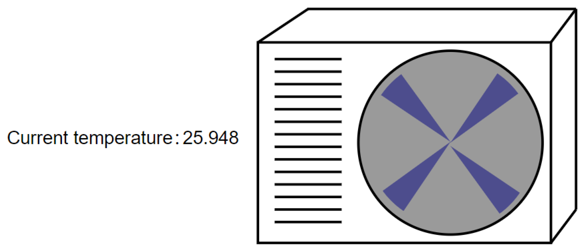
- We simulated the room with a length, width, and height of 5 m × 5 m × 5 m. The room has a vent with a length of 0.5 m × 0.2 m, and we assumed that there is no other heat dissipation in the room except for the vent.
- We simulated the heat source as 130 w, and we assume that there is no other heat source in the room.
- We simulated the cooling capacity of the air conditioner, and we assumed that there were no other sources of cooling in the room.
- The start time of this simulation is 00:00 and the simulation time unit is s. The total run time is more than 6000 s.
- To simplify the modeling work, we simplified the basic information model of the BIPM-based air conditioning model.
- In this analysis, the initial indoor temperature is set to 26 °C, and the air conditioner preset temperature is 20 °C.
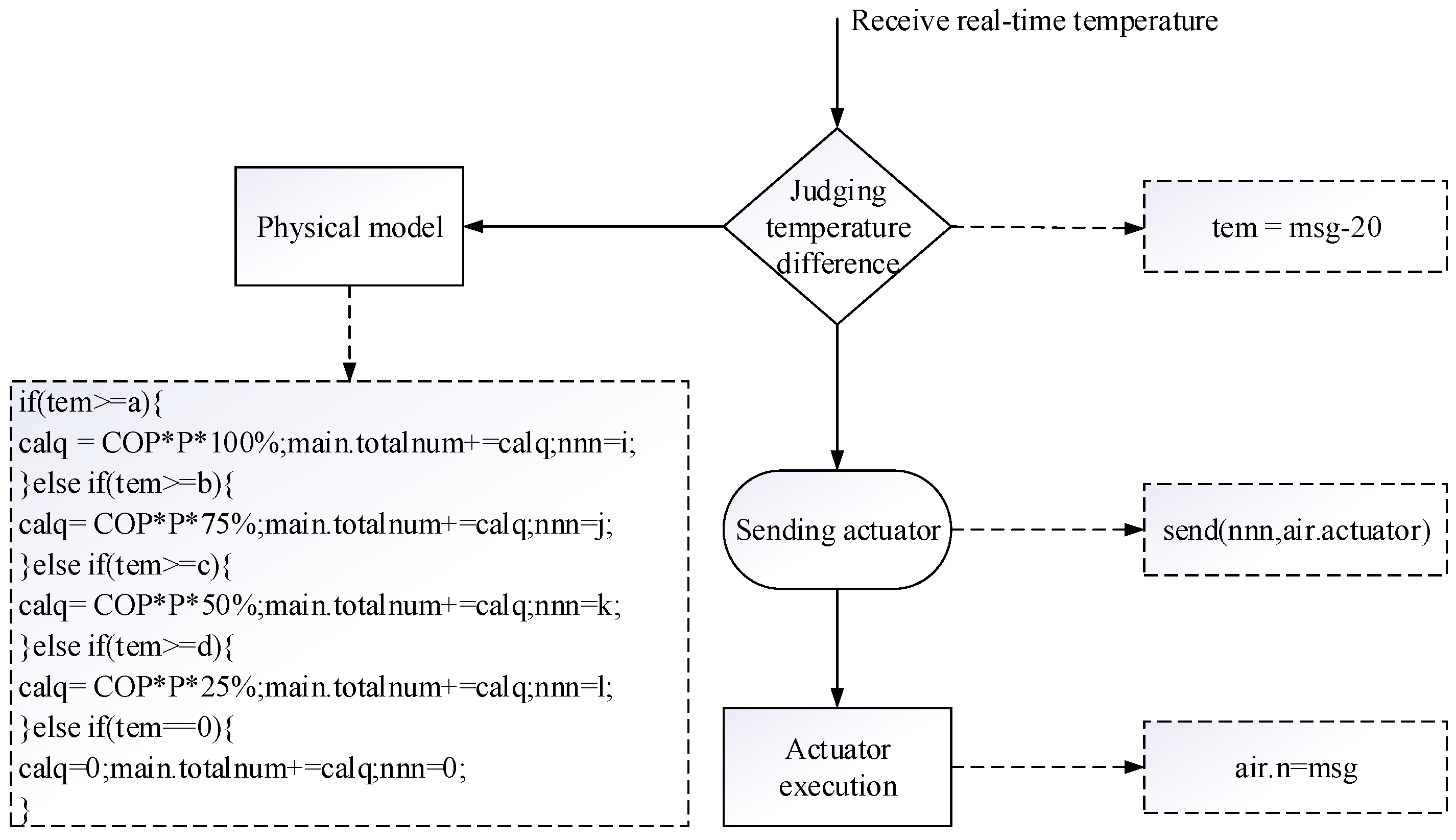
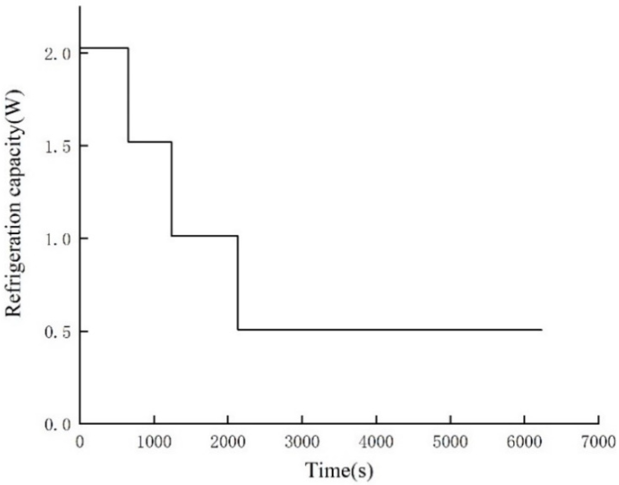
- In this paper, to simplify the calculation of the physical model, the temperature difference (tem) is set to five stages: a > b > c > d > 0. At this time, the corresponding percentage of the cooling capacity is 100%, 75%, 50%, 25%, and 0, and the corresponding air conditioner speed (nnn) is i > j > k > l > 0.
- (2)
- Simulation models
- (3)
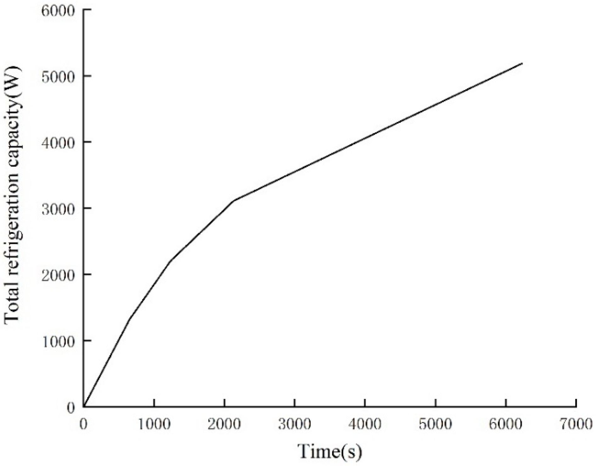
- Simulation results and analysis
7. Conclusions
- The system structure and behavioral logic of the BIPM is constructed based on the UML normative modeling method, which solves the defects of the traditional method in the verification of logical consistency and dynamic interaction mechanism.
- By transforming the BIPM behavioral logic into TANs, formal validation is achieved to guarantee the rigor of the dynamic interaction mechanism.
- The AnyLogic tool maps the BIPM structural model into a visual simulation model, which supports the real-time dynamic display and performance analysis of building system behaviors, enhances the interpretability of the model, and provides an intuitive decision support platform for the stakeholders.
- An empirical study using an air conditioning system as a case study shows that the method can effectively integrate the rigor of formal verification with the engineering suitability of dynamic visualization techniques, verifying the feasibility and effectiveness of the framework in the collaborative verification of complex dynamic systems.
Author Contributions
Funding
Data Availability Statement
Conflicts of Interest
References
- Yang, H.L.; Xia, M. Advancing bridge construction monitoring: AI-based building information modeling for intelligent structural damage recognition. Appl. Artif. Intell. 2023, 37, 2224995. [Google Scholar] [CrossRef]
- Kong, L.L.; Yang, Q.L.; Zhou, Q.Z.; Xing, J.C.; Sun, X.B.; Zou, R.W. Embedding knowledge into BIM: A Case Study of Extending BIM with Firefighting Plans. J. Build. Eng. 2022, 49, 103999. [Google Scholar] [CrossRef]
- Zhang, T.R.; Doan, D.T.; Kang, J. Application of Building Information Modeling-Blockchain Integration in the Architecture. Engineering, and Construction/Facilities Management Industry: A review. J. Build. Eng. 2023, 77, 107551. [Google Scholar] [CrossRef]
- Markets, R.A. Building Information Modeling (BIM)—Global Strategic Business Report. 2023. Available online: https://www.researchandmarkets.com/reports/4804704/building-information-modeling-bim-global#product--description (accessed on 2 October 2024).
- Sacks, R.; Barak, R. Impact of three-dimensional parametric modeling of buildings on productivity in structural engineering practice. Automat. Constr. 2008, 17, 439–449. [Google Scholar] [CrossRef]
- Bryde, D.; Broquetas, M.; Volm, J.M. The project benefits of Building Information Modeling (BIM). Int. J. Project. Manage 2013, 31, 971–980. [Google Scholar] [CrossRef]
- Poirier, E.A.; Staub-French, S.; Forgues, D. Forgues, Measuring the impact of BIM on labor productivity in a small specialty contracting enterprise through action-research. Automat. Constr. 2015, 58, 74–84. [Google Scholar] [CrossRef]
- Liu, J.F.; Ji, Q.K.; Zhou, H.G.; Du, C.X.; Liu, X.J.; Li, M.X. A multi-dimensional evolution modeling method for digital twin process model. Robot. Comput.-Integr. Manuf. 2024, 86, 102667. [Google Scholar] [CrossRef]
- Önden, İ.; Pamucar, D.; Deveci, M.; As, Y.; Birol, B.; Yildiz, F.Ş. Prioritization of transfer centers using GIS and fuzzy Dombi Bonferroni weighted Assessment (DOBAS) model. Expert Syst. Appl. 2024, 238, 121827. [Google Scholar] [CrossRef]
- Yang, Q.L.; Xing, J.C. Building Information and Physical Model (BIPM): A novel form of information description for buildings. Strateg. Study Chin. Acad. Eng. 2023, 25, 222–232. [Google Scholar] [CrossRef]
- Kong, L.L.; Yang, Q.L.; Zhou, Q.Z.; Xing, J.C.; Chen, Y. Formal modeling and validation of a novel building information model. Adv. Eng. Softw. 2024, 197, 103761. [Google Scholar] [CrossRef]
- Elsayed, P.; Mostafa, H.; Marzouk, M. BIM based framework for building evacuation using Bluetooth Low Energy and crowd simulation. J. Build. Eng. 2023, 70, 106409. [Google Scholar] [CrossRef]
- Hu, X.; Olgun, G.; Assaad, R.H. An intelligent BIM-enabled digital twin framework for real-time structural health monitoring using wireless IoT sensing, digital signal processing, and structural analysis. Expert Syst. Appl. 2024, 252, 124204. [Google Scholar] [CrossRef]
- Gourabpasi, A.H.; Nik-Bakht, M. BIM-based automated fault detection and diagnostics of HVAC systems in commercial buildings. J. Build. Eng. 2024, 87, 109022. [Google Scholar] [CrossRef]
- Hosseinnezhad, D.; Nugroho, Y.K.; Heavey, C. Horizontal collaboration between suppliers to mitigate supply chain disruption: A secure resource sharing strategy. Comput. Ind. Eng. 2023, 177, 109088. [Google Scholar] [CrossRef]
- Khan, M.S.; Park, J.; Seo, J. Geotechnical property modeling and construction safety zoning based on GIS and BIM integration. Appl. Sci. 2021, 11, 4004. [Google Scholar] [CrossRef]
- Lu, Y.; Liu, C.; Kevin, I.; Wang, K.; Huang, H.; Xu, X. Digital Twin-driven smart manufacturing: Connotation, reference model, applications and research issues. Robot. Comput.-Integr. Manuf. 2020, 61, 101837. [Google Scholar] [CrossRef]
- Zhou, L.; Lin, J.; Li, Y.; Zhang, Z. Innovation diffusion of mobile applications in social networks: A multi-agent system. Sustainability 2020, 12, 2884. [Google Scholar] [CrossRef]
- Zhang, H.; Li, J.; Fei, Y.; Deng, C.; Yi, J. Capacity assessment and analysis of vertiports based on simulation. Sustainability 2023, 15, 13377. [Google Scholar] [CrossRef]
- Guo, W.; Chen, S.; Lei, M. Evolutionary game and strategy analysis of carbon emission reduction in supply chain based on system dynamic model. Sustainability 2023, 15, 8933. [Google Scholar] [CrossRef]
- Kim, J. Smart city trends: A focus on 5 countries and 15 companies. Cities 2022, 123, 103551. [Google Scholar] [CrossRef]
- Xu, J.D.; Jiong, P.; Cui, T.R.; Zhang, S.; Yang, Y.; Ren, T.L. Recent progress of tactile and force sensors for human-machine interaction. Sensors 2023, 23, 1868. [Google Scholar] [CrossRef] [PubMed]
- Jiao, Z.D.; Du, X.L.; Liu, Z.S.; Liu, L.; Sun, Z.; Shi, G.L.; Liu, R.R. A review of theory and application development of intelligent operation methods for large public buildings. Sustainability 2023, 15, 9680. [Google Scholar] [CrossRef]
- Papadopoulos, T.; Evangelidis, K.; Evangelidis, G.; Kaskalis, T.H. Mixed reality and the Internet of Things: Bridging the virtual with the real. Adv. Eng. Softw. 2023, 185, 103527. [Google Scholar] [CrossRef]
- Benveniste, A.; Raclet, J.B. Mixed nondeterministic-probabilistic automata. Discret. Event Dyn. Syst. 2023, 33, 455–505. [Google Scholar] [CrossRef]
- Shelekhov, V.I. Automata-based software engineering with Event-B. Program. Comput. Softw. 2023, 49, 470–483. [Google Scholar] [CrossRef]
- Yuan, J.; Aoki, T.; Guo, X. Comprehensive evaluation of file systems robustness with SPIN model checking. Softw. Test. Verif. Reliab. 2022, 32, e1828. [Google Scholar] [CrossRef]
- Grobelna, I.; Szcześniak, P. Model checking autonomous components within electric power systems specified by interpreted Petri nets. Sensors 2022, 22, 6936. [Google Scholar] [CrossRef] [PubMed]
- Rehman, A.; Akhtar, N.; Alhazmi, O.H. Formal modeling, proving, and model checking of a flood warning, monitoring, and rescue system-of-systems. Sci. Program. 2021, 2021, 6685978. [Google Scholar] [CrossRef]
- Chehida, S.; Baouya, A.; Bensalem, S.; Bozga, M. Learning and analysis of sensors behavior in IoT systems using statistical model checking. Softw. Qual. J. 2022, 30, 367–388. [Google Scholar] [CrossRef]
- Li, S.L.; Yang, Q.L.; Xing, J.C.; Chen, W.J.; Zou, R.W. A Foundation model for building digital twins: A case study of a chiller. Buildings 2022, 12, 1079. [Google Scholar] [CrossRef]
- Shaikh, E.; Al-Ali, A.R.; Muhammad, S.; Mohammad, N.; Aloul, F. Security analysis of a digital twin framework using probabilistic model checking. IEEE Access 2023, 11, 26358–26374. [Google Scholar] [CrossRef]
- Suhail, S.; Malik, S.U.R.; Jurdak, R.; Hussain, R.; Matulevičius, R.; Svetinovic, D. Towards situational aware cyber-physical systems: A security-enhancing use case of blockchain-based digital twins. Comput. Ind. 2022, 141, 103699. [Google Scholar] [CrossRef]
- Do, C.M.; Phyo, Y.; Riesco, A.; Ogata, K. Optimization Techniques for Model Checking Leads-to Properties in a Stratified Way. ACM Trans. Softw. Eng. Methodol. 2023, 32, 1–38. [Google Scholar] [CrossRef]
- Foughali, M.; Hladik, P.E.; Zuepke, A. Compositional verification of embedded real-time systems. J. Syst. Archit. 2023, 142, 102928. [Google Scholar] [CrossRef]
- Alkhatib, G. Structured methodologies vs UML artifacts revisited: A perspective from a developing country. Procedia Comput. Sci. 2024, 239, 2090–2097. [Google Scholar] [CrossRef]
- Okano, K.; Onishi, M.; Otsuka, J.; Ogata, S.; Sekizawa, T.; Okamoto, K.; Bekki, D. A bounded model checker for Timed Automata and its application to LTL properties. Procedia Comput. Sci. 2022, 207, 532–541. [Google Scholar] [CrossRef]
- Afanasyev, M.; Pervukhin, D.; Kotov, D.; Davardoost, H.; Smolenchuk, A. System modeling in solving mineral complex logistic problems with the anylogic software environment. Transp. Res. Procedia 2023, 68, 483–491. [Google Scholar] [CrossRef]


| Study | Methodology | Strengths | Limitations of Existing Methods | Innovations of Proposed Framework |
|---|---|---|---|---|
| Benveniste et al. [25] | Hybrid automata | Probabilistic system validation | Limited to static systems | Dynamic systems |
| Shaikh et al. [32] | Probabilistic model checking | Enhanced security for DT frameworks | State space explosion issues | Symmetry-aware structural–temporal preservation |
| Grobelna et al. [28] | Interpreted Petri nets | Power system validation | Ignores temporal constraints | TA-based temporal logic verification |
| Proposed Framework | TA-UML-AnyLogic | Combines formal rigor with dynamic visualization | — | Unified validation across formal models, simulations, and physical interactions |
| Relationship | Semantic | Description |
|---|---|---|
| Input | A [c];B | If the condition c in class A is satisfied, the operation in class B is performed. |
| Driven | A→DB | Denotes a driving relationship, where A will adjust B’s behavior according to the monitoring status. |
| Sensory | A→SB | Denotes a monitoring relationship, where A will detect the operational status and data of B. |
| Execute | A→EB | Denotes a regulating relationship, where A will adjust the parameters or behavior of B according to the control instructions. |
| Establish | A;B [e1]||C [e2] | If the condition e1 in class A is satisfied, the physical model of class B is established. If the condition e2 in class A is satisfied, the physical model of class C is established. |
| Instruction | A;B [c1]||C [c2] | If condition c1 in class A is satisfied, B instruction is sent; if condition c2 in class A is satisfied, C instruction is sent. |
Disclaimer/Publisher’s Note: The statements, opinions and data contained in all publications are solely those of the individual author(s) and contributor(s) and not of MDPI and/or the editor(s). MDPI and/or the editor(s) disclaim responsibility for any injury to people or property resulting from any ideas, methods, instructions or products referred to in the content. |
© 2025 by the authors. Licensee MDPI, Basel, Switzerland. This article is an open access article distributed under the terms and conditions of the Creative Commons Attribution (CC BY) license (https://creativecommons.org/licenses/by/4.0/).
Share and Cite
Kong, L.; Yang, Q.; Zhang, Y.; Zhang, X.; Zhou, Q. Symmetry-Aware Hybrid Verification for Complex Building Information Systems. Symmetry 2025, 17, 726. https://doi.org/10.3390/sym17050726
Kong L, Yang Q, Zhang Y, Zhang X, Zhou Q. Symmetry-Aware Hybrid Verification for Complex Building Information Systems. Symmetry. 2025; 17(5):726. https://doi.org/10.3390/sym17050726
Chicago/Turabian StyleKong, Linlin, Qiliang Yang, Yaoqin Zhang, Xuewei Zhang, and Qizhen Zhou. 2025. "Symmetry-Aware Hybrid Verification for Complex Building Information Systems" Symmetry 17, no. 5: 726. https://doi.org/10.3390/sym17050726
APA StyleKong, L., Yang, Q., Zhang, Y., Zhang, X., & Zhou, Q. (2025). Symmetry-Aware Hybrid Verification for Complex Building Information Systems. Symmetry, 17(5), 726. https://doi.org/10.3390/sym17050726