Article

Influence of Bore Parameters and Effective Mass Ratio on the Launching Accuracy of Electromagnetic Launchers

1
Institute of Electrical Engineering, Chinese Academy of Sciences, Beijing 100190, China
2
School of Electronic, Electrical and Communication Engineering, University of Chinese Academy of Sciences, Beijing 100049, China
*
Author to whom correspondence should be addressed.
Symmetry 2025, 17(3), 404; https://doi.org/10.3390/sym17030404
Submission received: 10 February 2025 / Revised: 27 February 2025 / Accepted: 7 March 2025 / Published: 8 March 2025
(This article belongs to the Section Engineering and Materials)

Abstract

:
An electromagnetic launcher is a kind of rail symmetrical distribution launcher. When a symmetrical current is passed between the rails, the strong magnetic field is symmetrically distributed between the two rails. The bore parameters affect the efficiency and accuracy of the launcher. Launching accuracy is an important evaluation content for assessing the technical index of the electromagnetic launcher. In this paper, experiments were carried out to investigate the influence factors of the launching accuracy of a small-caliber electromagnetic launcher. The experimental results show that: (1) The consistency of the muzzle velocity increases with the increase of the rail separation. When the rail separation is 16 mm, the mean deviation of the muzzle velocity is the smallest, at 16.71, 15.72, and 10.77, respectively. When the rail separation is constant, the mean deviation of the muzzle velocity is 10.77, while the convex arc height is 1 mm. Increasing the rail separation and the convex arc height is beneficial to improving the consistency of the initial velocity. (2) When the rail separation is certain, increasing the convex arc height significantly improves the firing accuracy and firing intensity, and when the convex arc height increases from 0 mm to 1 mm, the firing intensity is reduced from 9.6 to 4.41, and the firing intensity decreases from 10.34 to 5.79, which significantly reduces the firing deviation and increases the muzzle consistency of the armature under repeated firing conditions. (3) The muzzle attitude is mainly affected by the effective mass ratio. Within a certain range, adding load can make the muzzle attitude of the integrated projectile more stable. However, when the load mass is too large, it will have a negative impact on the muzzle attitude. The results show that under the two cases of the effective mass ratio of 0.43 and 0.49, the integrated projectile has a better muzzle attitude.

1. Introduction

Electromagnetic launch technology is a launching method that uses electromagnetic force to accelerate the load to high speed or even ultra-high speed [1]. Compared with traditional chemical and mechanical launch methods, the electromagnetic launcher has the advantages of high muzzle velocity, strong controllability, high safety, and wide application range. An electromagnetic launcher is a type of electromagnetic launch technology. Its typical schematic diagram is shown in Figure 1 [2,3]. It mainly consists of two parallel rails and an armature that maintains good contact with the rails. The armature can move directionally along the rails. As a new-concept launching method, it has a completely different launching process from traditional chemical-energy launches. Traditional chemical-energy launches rely on the expansion work of high-temperature and high-pressure gas generated by gunpowder combustion in a closed chamber to push the projectile to move directionally and accelerate the projectile to high speed [4,5]. In an electromagnetic launcher, the electromagnetic force generated by the current is used to drive the armature. After the current is fed into one of the rails, it forms a closed loop through the rails and the armature. Under the combined influence of the magnetic field and the current, a huge electromagnetic force is generated to drive the armature to move directionally along the rails, achieving high muzzle velocity [6,7,8,9,10].
In traditional artillery systems, launching accuracy serves as a key indicator of combat effectiveness, reflecting the system’s ability to hit a target under specific conditions [11]. Launching accuracy is primarily influenced by equipment design, ammunition consistency, environmental conditions, and operational methods. It typically refers to the proximity of the projectile’s point of impact to the target under varying ballistic factors and external conditions during the firing process. Generally, launching accuracy serves as a key reference metric for quantifying the system’s performance stability and targeting capability [12,13]. Due to the characteristics of the electromagnetic launcher, it has a wide range of applications in the military, aerospace, and civilian fields. First of all, in the field of national defense, it can be used for aircraft ejection take-off from aircraft carriers, short-range defense of naval vessels, long-range land strikes, extended fire delivery, coastal defense, and land-based missile launches. In the aerospace field, it can be employed to mitigate the accumulation of space debris and launch probes into orbit around the earth or the moon, which can significantly reduce launch costs, and can also be used for spacecraft transfer and attitude adjustment. In the civilian field, it can also be applied for firefighting, electromagnetic metal forming, etc.
As a type of launching system, research on the launching accuracy of electromagnetic launchers is essential for advancing their engineering applications. Few public studies address the launching accuracy of electromagnetic launchers, and both domestic and international research in this area remains in its early stages. The analysis of launching accuracy is a multidisciplinary field, encompassing flight mechanics, control theory, and statistics. Firstly, electromagnetic launching is a complex process that involves the coupling of electrical, magnetic, thermal, and mechanical physical fields. The launching process occurs within a few milliseconds, with the driving current reaching hundreds of thousands of amperes or even megamperes. Under these extreme conditions, changes in material properties, vibrations of the launcher, and electromagnetic interference within a strong magnetic field can significantly impact the accuracy of the launcher system. Therefore, achieving high-precision launches presents substantial challenges. So, studying the launching accuracy of electromagnetic launchers is highly significant. Lloyd G. Allred [14,15,16] proposed a precise method to calculate the confidence interval for CEP and developed an estimation method that includes design accuracy under horizontal dispersion conditions. In 2013, John Gallant [17] analyzed the performance of electromagnetic launchers. By constructing a simulation model, they calculated hit probabilities for projectiles with muzzle velocities ranging from 1200 m/s to 2400 m/s and launch frequencies between 75 and 300 rounds per second. In 2015, Shang Xiaobing [18] developed an outer ballistic model and an analysis framework for factors affecting the launching accuracy of electromagnetic launchers, providing a detailed evaluation process for launching accuracy. In 2017, Ma Ping [19] proposed a general framework including trajectory simulation, data preprocessing, parameter estimation, and hit probability calculation to evaluate shooting accuracy of EMRG. Using the designed framework and the proposed experimental design method, the shooting accuracy of a 16-kg projectile was evaluated. The results show that the probability of circular error is about 5 km. In 2018, Chen Liyan [20] analyzed error sources affecting the muzzle velocity of electromagnetic launchers. They established a internal ballistic model and simulated the in-bore motion process, demonstrating that discharge voltage and capacitance exert the greatest influence on muzzle velocity. In 2019, Ma Ping [21] developed a railgun external trajectory simulation model to analyze the ballistic behavior of missile targets during interception missions. The model compares firing range and efficiency to assess guidance accuracy. In addition, sensitivity analysis and shooting accuracy evaluations are performed to quantify uncertainty. The simulation results indicate that the modeling of guided projectiles can provide valuable insights for the design of electromagnetic railgun (EMRG) projectiles. In 2021, Tang Xiaoyan [22] studied methods for calculating electromagnetic launching accuracy. They extended the conventional CEP50 metric to CEP70 and CEP80 and introduced two novel methods: the maximum envelope method and the graphic method. In 2024, Zhang Qingxia [23] analyzed the effect of the manufacturing accuracy of rectangular and reverse arc inner holes on the firing accuracy of electromagnetic launch weapons under the same other firing conditions. The results show that the firing accuracy of the armature at the exit of the hole in the reverse arc is better than that of the rectangular section. The firing error of the assembly gap between the armature and the guide rail is much larger than that caused by the straightness of the firing hole, which can provide technical support for improving the firing accuracy of the weapon system in the future. These studies primarily focus on theoretical and simulation-based analysis, with limited experimental exploration of critical performance metrics like shooting accuracy and projectile bore attitude. Therefore, experimental research on the launch accuracy of electromagnetic launchers is of great importance.
In this study, the influence of bore parameters and effective mass ratio on the launching accuracy of electromagnetic launchers were investigated by experiments. Nine sets of experiments were conducted to examine the influence of rail separation and convex arc height on launching accuracy, as well as the effects of effective mass ratio under varying bore parameters. Each test was repeated three times to minimize random errors. The influence of each parameter on launching accuracy was assessed based on the consistency of muzzle velocity, firing accuracy, firing intensity, and muzzle attitude, providing valuable guidance for the development of electromagnetic launchers.

2. Definition and Calculation Method of Launching Accuracy of Electromagnetic Launchers
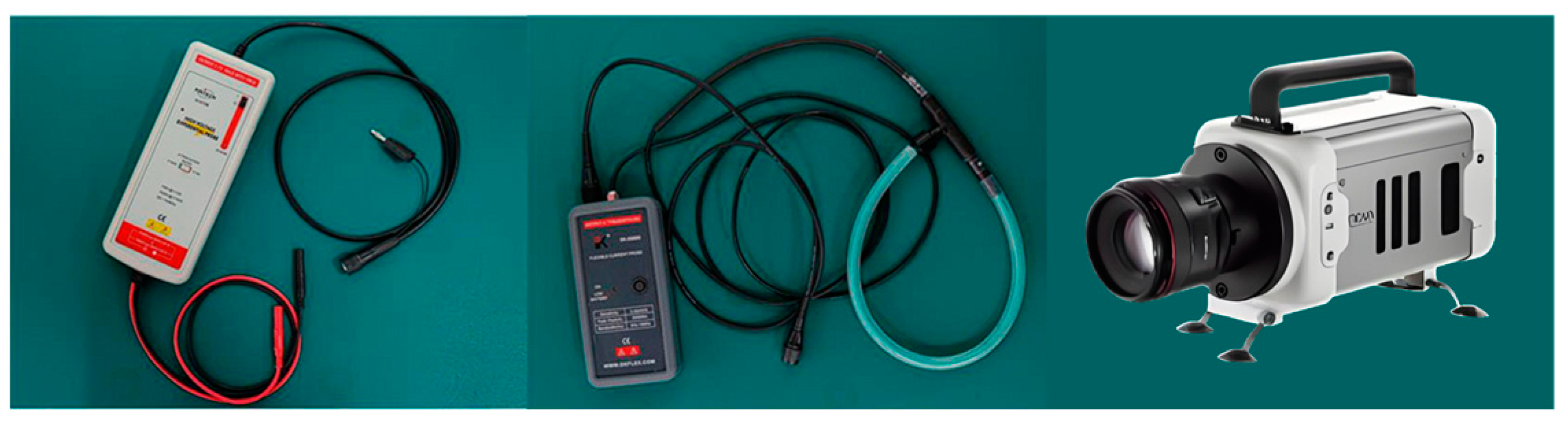
Launch accuracy is a key tactical metric for evaluating electromagnetic launchers. Traditional artillery systems use metrics such as circular probability error (CEP) and shooting dispersion to characterize launching accuracy. In this paper, the consistency of muzzle velocity, firing accuracy, firing intensity, and muzzle attitude of the projectile are selected as indices to evaluate the launching accuracy of the electromagnetic launchers. The consistency of muzzle velocity is defined as the average error of muzzle velocity compared with the average muzzle velocity. The mean deviation, standard deviation, relative mean deviation, and relative standard deviation can be calculated to assess the consistency of muzzle velocity. Firing accuracy is defined as the deviation between the average firing position and the center of the target. The firing intensity refers to the average deviation of each Integrated Launch Package (ILP) landing point relative to the average landing point position on the target paper and the bore muzzle attitude refers to the attitude photos taken by the high-speed camera at the time of integrated ejection of the bore. The changes of the attitude under different conditions can be assessed and compared through the photos, taken continuously [24].
The stability of sliding electric contact during the launching process of the electromagnetic launcher is an important factor influencing launch performance. The consistency of the muzzle velocity serves as a specific indicator for evaluating the movement process, which includes assessing the adequacy of contact between the armature and the rails, the stability of the armature’s motion in the bore, and variations in the capacitor discharge waveform. Consequently, the consistency of muzzle velocity is considered one of the evaluation indices for launching accuracy. The theoretical muzzle velocity of this paper is 800 m/s, and the mean deviation (D1), standard deviation (D2), relative mean deviation (D3), and relative standard deviation (D4) are selected as evaluation indices to assess the consistency of muzzle velocity. The calculation methods for each index are as follows [19]:
D 1 = i = 1 n v i v ¯ n
D 2 = D 1 v ¯ × 100 %
D 3 = i = 1 n v i v ¯ 2 n
D 4 = D 3 v ¯ × 100 %
where vi is the muzzle velocity, v ¯ is the average muzzle velocity of the group of tests, and n is the number of experiments.
Because the experiments were carried out in the laboratory and the distance between the paper target and the muzzle was 1 m, and because of the limited number of experiments, it was not possible to fully calculate the traditional gun launching accuracy index. Instead, firing accuracy and firing intensity were used as the primary criteria for evaluating the launching accuracy of the electromagnetic launchers. Launching accuracy, also known as multivariate error, is defined as the deviation between the average impact point of the projectile and the theoretically predicted impact point. Firing intensity, also referred to as dispersion error, is defined as the deviation of the impact point from the average impact point. Each group of experiments, involving different internal bore parameters, required reassembly of the experimental device and the installation of a new paper target. Consequently, the theoretical impact point was redefined for each group of experiments and set as the coordinate origin P = (0,0). The projectile impact point pi = (xi,yi) represents the landing position and coordinates of the i-th projectile, while p ¯ = x ¯ ,   y ¯   represents the average position and coordinates of all projectile landing points. Firing accuracy σ1 and fire intensity σ2 are expressed as follows:
σ 1 = x ¯ 0 2 + y ¯ 0 2 = x ¯ 2 + y ¯ 2
σ 2 = i = 1 n x i x ¯ 2 + y i y ¯ 2 n
where xi is the horizontal coordinate of the impact point in the i-th test, yi is the vertical coordinate of the impact point in the i-th test, x ¯ is the horizontal coordinate of the average location of the projectile’s impact points, y ¯ is the vertical coordinate of the average location of the projectile’s impact points, and n represents the number of launches conducted under the given test conditions.
For weapon systems, the muzzle attitude plays a critical role in influencing the flight characteristics of both the intermediate and outer trajectories. The muzzle attitude directly affects the stability, accuracy, and flight performance of the projectile during its outer trajectory. A poor muzzle attitude can result in trajectory deviations, thereby reducing overall firing accuracy. This issue is particularly critical in long-range shooting, where even a small initial deviation in the exit angle can be amplified, causing the projectile to deviate significantly from the intended target and increasing the firing error. As a result, achieving a stable and reliable muzzle attitude is essential for ensuring launching accuracy. In this experiment, high-speed camera imaging was utilized to analyze the muzzle attitude.

3. Experiment Setup

A total of nine groups of control tests were conducted in this study, with each test repeated three times to minimize random errors. After each test, aluminum residue deposited on the rails was cleaned to maintain consistent initial experimental conditions. In each experimental group, paper targets were replaced to record the impact points of the armature, and the theoretical impact point under the same conditions was recalculated. The test equipment primarily consisted of a small-caliber launcher, a 270-kJ pulse power supply, and a power control system. The test platform, as shown in Figure 2, included a hydraulic loading device, bus bar, cables, small-caliber launcher, silencing chamber, and armature collection box. The hydraulic loading device positioned the armature at a specified location within the chamber, while the bus bar collected electrical energy from the cable and delivered it to the guide rail. The armature collection box was used to retrieve the armature following its launch. Measurement devices are shown in Figure 3. Those used in the experiment included a high-speed camera, Rogowski coil, paper target, B-magnetic probe, and a high-voltage differential probe, among others. The high-speed camera was employed to capture the muzzle attitude of the armature, while the Rogowski coil measured the drive current. The paper target was used to determine the armature’s impact point after bore and to calculate firing accuracy and firing intensity. The B-dot probe measured the movement of the armature in the bore, and the high-voltage differential probe captured the voltage at the muzzle and breech.
Figure 4 and Figure 5 illustrate the cross-section and bore parameters of the launcher, and the experiments primarily involved two types of rails: a plane rail and a convex arc rail, with convex arc heights of 0.5 mm and 1 mm, respectively. Key rail parameters included the contact height (ha) between the armature and the rail, the rail height (hr), and the rail separation (s). For convex arc rails, the rail separation (s) is defined as the distance between the highest points of the convex arc. Additional parameters for the convex arc rail include the convex arc height (s2), the convex arc chord length (hc), the central angle (θ), and the arc radius (R). In these experiments, variations in convex arc height (s2) and rail separation (s) were introduced to investigate the influence of cross-section dimensions on the launching accuracy. The ILP in the experiments was primarily composed of an aluminum alloy armature, a stainless-steel load serving as the effective mass, and a polycarbonate guide. While the cross-section dimensions remained unchanged, the armature mass was kept constant by controlling experiment variables, with only the load mass modified. This approach introduced changes in both the total ILP mass and the effective mass ratio, which was set to values of 0, 0.28, 0.43, 0.49, and 0.56. The objective was to comprehensively investigate the influence of varying the effective mass ratio on the launching accuracy. To guarantee uniform acceleration of the ILP in the bore, the mass of the ILP was maintained within the range of 8.4 g to 18.7 g. The effects of electromagnetic force, mechanical force, and friction were thoroughly evaluated using theoretical calculations. The calculations indicated that the amplitude of the driving current was determined to range between 175 kA and 250 kA to ensure the correctness and dependability of the experimental results. Figure 6 illustrates the driving current waveforms corresponding to various effective mass ratios.

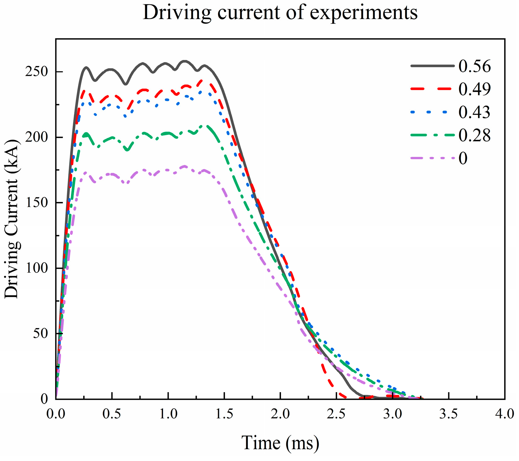
4. Results and Discussion of Experiments

4.1. Influence of Bore Parameters on Consistency of Muzzle Velocity

During the experiment procedure, to precisely regulate the variables, mitigate the possible influence of extraneous influences on the results, and guarantee the correctness and scientific integrity of the experimental data, we established and maintained the muzzle velocity at 800 m/s. This guarantees that each armature experiences an identical acceleration process in the bore, hence minimizing data deviation resulting from variations in the acceleration process and offering a more reliable foundation for later analysis and study.
Figure 7, Figure 8, Figure 9 and Figure 10 show the distribution analysis of muzzle velocity in each set of experiments. Figure 7 and Figure 8 are the mean deviation and standard deviation of muzzle velocity in each group of experiments. It can be observed that when the convex arc height remained constant, with the increase of rail separation, the mean deviation fell from 33.49 to 16.71, from 31.14 to 15.72, and from 21.79 to 10.77, respectively. The standard deviation of each group was lowered from 43.64 to 18.33, from 35.39 to 14.96, and from 25.12 to 14.21, respectively. When the rail separation is unchanged, the mean deviation reduces from 33.49 to 16.71, from 31.14 to 15.72, and from 21.79 to 10.77, respectively, with the rise of the convex arc height. The standard deviation was lowered from 43.64 to 25.12, from 27.08 to 22.81, and from 18.33 to 14.21, respectively. To present the results more comprehensibly, the mean deviation and standard deviation were standardized to generate the relative mean deviation and standard deviation. As shown in Figure 9 and Figure 10, the changing trend of the relative mean deviation and standard deviation was largely similar to that of the mean deviation and standard deviation, and the tiny variation was caused by the various average muzzle velocities of each set. As can be observed from the data in the figure, the relative mean deviation and relative standard deviation steadily decrease with the increase in rail separation. When the rail separation reaches 16 mm, the relative mean deviation and relative standard deviation of various rail separations reduce to less than 2.5%. This illustrates that when the rail separation is 16 mm, the difference in muzzle velocity is minimized, and the consistency of muzzle velocity is enhanced. When the rail separation is constant, the relative mean deviation and relative standard deviation reach the minimum when the convex arc height is 1 mm. Taking s = 14 mm as an example, the relative mean deviation of convex arc 0 mm, convex arc 0.5 mm, and convex arc 1 mm are 4.08%, 3.74%, and 2.62%, respectively. The relative standard deviation is 5.31%, 4.25%, and 3.09%, respectively. The muzzle velocity of s = 15 and s = 16 mm has the same fluctuation pattern, which suggests that the muzzle velocity has the greatest consistency when the convex arc height is 1 mm. According to the statistics, the rail with a rail separation of 16 mm and convex arc height of 1 mm has a superior consistency of muzzle velocity. This is because when the rail has a convex arc, the current is more evenly distributed on the rail, the contact force is more evenly distributed, and the electrical contact performance of the contact surface of the mature rail is better, which reduces the molten aluminum and aluminum deposition caused by local heat accumulation during the launch process, ensuring the repeatability and stability of the multiple launch.

4.2. Influence of Bore Parameters on Firing Accuracy and Firing Intensity

In the evaluation of artillery firing performance, the firing accuracy and firing intensity are essential technical measures, which represent the distribution range and concentration of the impact point after numerous firings of the artillery system. With reference to the ideas of firing accuracy and firing intensity in conventional artillery, the firing intensity and accuracy of electromagnetic launchers are investigated.
In this study, paper targets are employed to collect the impact point location once the ILP is unloaded. The impact point coordinates of all experiments are presented in Figure 11 (0–14 of the picture denotes the convex arc height of 0 mm, rail separation of 14 mm, and so on). It can be observed from the figure that there are variances in off-center location and dispersion intensity with different bore parameters. As the convex arc height grows, the location of the impact point gets denser. The average impact point location under varied bore parameters is given in Figure 12.
As can be observed from Figure 12, in the three sets of tests in which the convex arc height rose from 0 mm to 1 mm, the average impact point on the paper target was closer to the coordinate origin, indicating that the firing accuracy was greater. When the convex arc height remained constant, the modification of the rail separation had no significant influence on the average impact point location. The calculated firing accuracy and firing intensity based on the experiment results are summarized in Table 1.
It can be observed from Table 1 that while the convex arc height is constant, the change in rail separation has no evident impact on the firing accuracy and intensity. However, while the rail separation is maintained, using s = 14 mm as an example, the firing accuracy is reduced from 9.60 to 4.41 as the convex arc height goes from 0 mm to 1 mm. The firing intensity decreases from 10.34 to 5.79. The same pattern persists when s = 15 mm and s = 16 mm, which indicates that the firing deviation and dispersion of the launcher are reduced when the convex arc height is increased, and the firing accuracy of the launcher under repeated firing state is obviously improved with the increase of the convex arc height. This is because compared with the flat rail, the contact between the rail and the armature is better under the condition of convex arc rail, and the convex arc contact also reduces the vibration of the armature in the moving process in the bore, improving the contact stability and the accuracy of muzzle velocity.

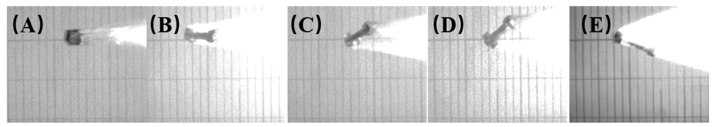
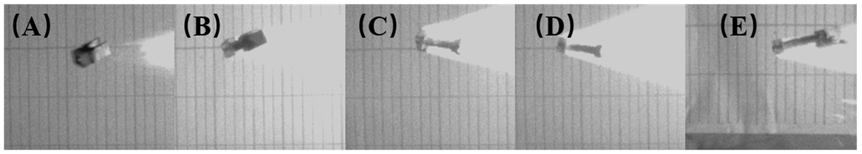
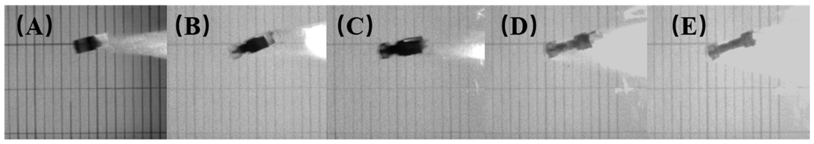
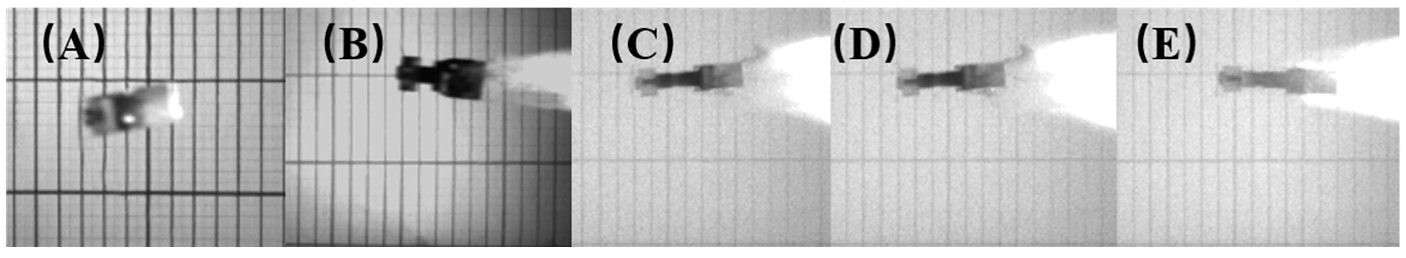
4.3. Influence of Bore Parameters and Effective Mass Ratio on Muzzle Attitude

As a kind of kinetic energy damage strike device, electromagnetic launchers mainly rely on the kinetic energy of the ILP to strike the target. The muzzle attitude of the ILP at ultra-high speed plays an important role in influencing the external ballistic trajectory during the flight and the hitting accuracy. Therefore, investigating the muzzle attitude of the electromagnetic launcher is of great value for enhancing the striking accuracy and damaging ability of the system. The muzzle attitude following the ILP is acquired largely by a high-speed camera. Figure 13, Figure 14, Figure 15, Figure 16, Figure 17, Figure 18, Figure 19, Figure 20 and Figure 21 demonstrate the muzzle attitude under various bore parameters. The effective mass ratio from left to right in each picture is 0, 0.28, 0.43, 0.49, and 0.56, respectively.

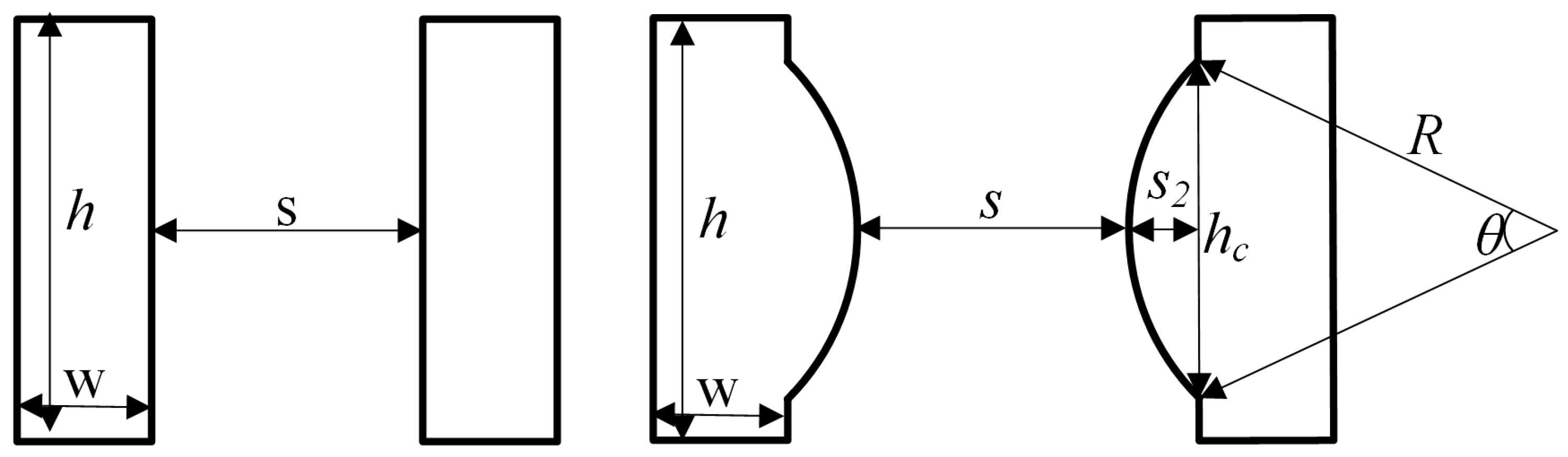
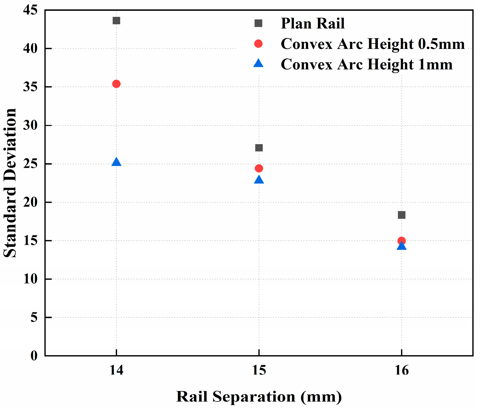
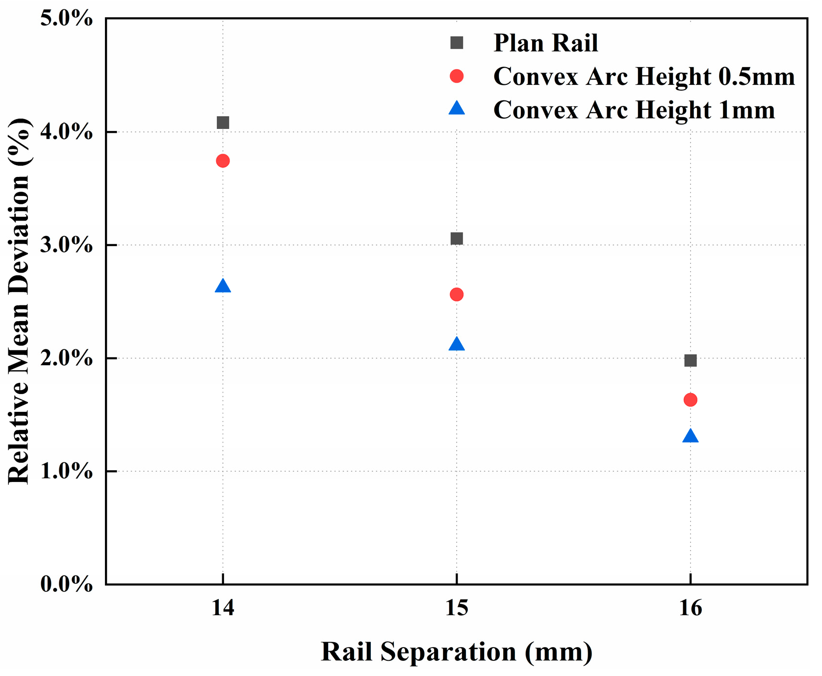
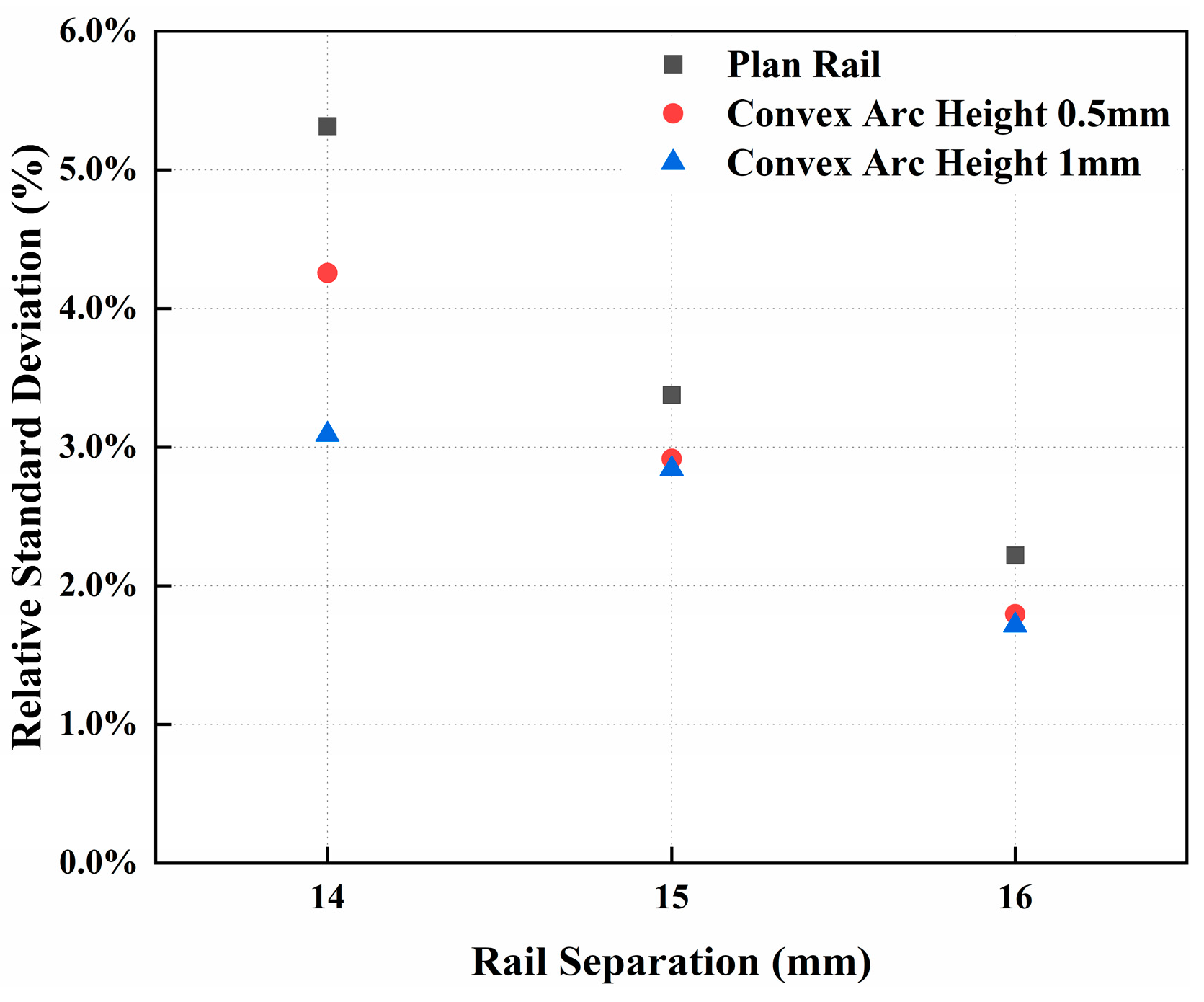
4.3.1. Effect of Rail Separation on the Muzzle Attitude

Figure 13, Figure 14 and Figure 15, Figure 16, Figure 17 and Figure 18, and Figure 19, Figure 20 and Figure 21 illustrate the muzzle attitude under the conditions of a plane rail, a 0.5 mm convex arc rail, and a 1 mm convex arc rail, respectively. By comparing the muzzle attitude photographs across the different groups, it can be observed that when the convex arc height remains constant, the muzzle attitude becomes increasingly stable as the rail separation increases. This is because, at smaller rail separations, the loading error is relatively larger in comparison to the rail separation itself. Conversely, at larger rail separations, the loading error becomes relatively smaller. Additionally, when the rail separation is reduced, the inductance gradient of the launcher decreases. The input current must be increased to obtain the same muzzle velocity. As the current increases, the heat generated by the armature moving through the bore also rises, significantly increasing the possibility of armature melting. This can result in unstable armature movement within the bore, thereby adversely affecting both the muzzle velocity and attitude.

4.3.2. Effect of Convex Arc Height on Muzzle Attitude

It can be observed from the figures that the convex arc height has a significant effect on the muzzle attitude. During the launching process, to ensure stable armature motion, the bore diameter of the experimental device should be slightly larger than the armature size. When the contact surface between the armature and the rail is flat, some loading errors are inevitable during the loading process. These errors prevent the armature from remaining perfectly horizontal, causing it to tilt up or down in the plane parallel to the rail. Consequently, the contact pressure between the armature and the rail becomes uneven on both sides. However, when the convex arc rail is used, the loading errors during the loading process are significantly reduced. The convex arc rail helps minimize the degree of tilting of the ILP along the arc plane. Additionally, the convex arc rail effectively clamps the armature along the arc plane, preventing it from deviating in the plane perpendicular to the launching direction. This ensures both stable motion of the armature and a consistent launch trajectory. Moreover, previous studies have demonstrated that the convex arc rail enhances the inductance gradient and promotes a more uniform distribution of current density. Thus, compared to a plane rail, the convex arc rail offers notable advantages in terms of stability and performance,

4.3.3. Effect of Effective Mass Ratio on the Muzzle Attitude

Figure 13, Figure 14, Figure 15, Figure 16, Figure 17, Figure 18, Figure 19, Figure 20 and Figure 21 depict the muzzle attitude for effective mass ratios of 0, 0.28, 0.43, 0.49, and 0.56, respectively, from left to right. A comparison of these figures reveals that when the effective mass ratio is 0, the armature exhibits significant tilting, either upward or downward, after exiting the bore. Increasing the distance between the contact position of the armature and the rail and the position relative to the guide reduces the tilt angle after loading. This adjustment also shifts the center of gravity of the ILP forward, thereby improving both the stability of the internal bore motion and the muzzle attitude of the projectile.
However, the muzzle attitude shown in Figure 16C, Figure 17C and Figure 18C and Figure 16D, Figure 17D and Figure 18D is more stable than that in Figure 16E, Figure 17E and Figure 18E. This indicates that the effective mass ratio must be in a suitable range to achieve optimal performance. Experimental results show that effective mass ratios of 0.43 and 0.49 yield better muzzle attitudes compared to other ratios. Conversely, an effective mass ratio of 0.56 results in a more unstable muzzle attitude. Therefore, to balance muzzle attitude and firing accuracy, it is recommended to use an effective mass ratio of 0.43 or 0.49.

5. Conclusions and Future Work

This paper experimentally investigates the effects of bore parameters and effective mass ratio on the launching accuracy of an electromagnetic launcher. A total of nine groups of launch experiments were conducted to study the influence of rail separation, convex arc height, and effective mass ratio on consistency of muzzle velocity, firing accuracy, firing intensity, and muzzle attitude. The key findings are summarized as follows:
(1)
Consistency of muzzle velocity:
The consistency of muzzle velocity improves with an increase in rail separation and convex arc height. When the rail separation is set to 16 mm, the average deviation of outlet velocity reaches its lowest values, measuring 16.71, 15.72, and 10.77 across the experiments. Furthermore, with a constant rail separation, the average muzzle velocity deviation is minimized at 10.77 when the convex arc height is 1 mm. These results indicate that increasing both rail separation and convex arc height contributes to maintaining consistent muzzle velocity during repeated launches.
(2)
Firing accuracy and firing intensity:
Firing accuracy and intensity are primarily influenced by the convex arc height. With a fixed rail separation, increasing the convex arc height significantly improves these metrics. For instance, as the convex arc height increases from 0 mm to 1 mm, firing intensity decreases from 9.6 to 4.41, and firing intensity decreases from 10.34 to 5.79. This demonstrates that a higher convex arc height markedly reduces firing deviations and enhances armature muzzle consistency under repeated firing conditions.
(3)
Muzzle attitude:
The muzzle attitude is primarily affected by rail separation and convex arc height, but it is more affected by the effective mass ratio. Experimental results show that adding load improves the stability of the muzzle attitude to some extent; however, excessive load mass negatively impacts stability. Comprehensive analysis indicates that the optimal muzzle attitude occurs when the effective mass ratio is 0.43 and 0.49.
This manuscript primarily investigated the influence of bore parameters and effective mass ratio on launch accuracy. Through this research, optimal bore parameters that result in high launch accuracy and favorable muzzle attitude can be identified. Furthermore, it allows for the determination of the effective mass ratio that supports optimal muzzle attitudes, thereby providing guidance for size matching between the rails and armature of the electromagnetic launcher, as well as mass matching between the armature and the payload. To a significant extent, it can inform the engineering applications of electromagnetic launchers.
Due to the limitations of the experimental equipment, this investigation only examined the ILP’s muzzle attitude from a single direction, and due to the limitation of the experimental time and place, only a few indicators in traditional artillery were used to evaluate the launching accuracy. In our future work, we plan to increase the number of experiments to ensure that the sample size meets the statistical requirements for traditional gun launching accuracy. We will also refine the indicators used to assess the launching accuracy of the electromagnetic launcher, adopting more scientific and robust metrics for evaluating launch accuracy. Furthermore, we aim to broaden the experimental range, focusing on expanding the parameter space, including rail separation and curvature, to study the influence of rail thickness and height on accuracy. Different materials will be tested, and adjustments will be made to the armature and rail materials to identify the optimal combinations. We also intend to extend the current small-caliber experiments to medium and large-caliber launchers, enhancing the caliber range of the entire study. This will involve increasing the energy levels and muzzle velocity to 1000 m/s or higher to meet practical launch scenario requirements, ultimately providing support for the application of the electromagnetic launcher.

Author Contributions

Conceptualization and validation, N.X.; writing—review and editing, P.Y.; supervision, P.Y. All authors have read and agreed to the published version of the manuscript.

Funding

This research received no external funding.

Data Availability Statement

Data are available on request due to restrictions, e.g., privacy or ethical.

Conflicts of Interest

The authors declare no conflicts of interest. The funders had no role in the design of the study; in the collection, analyses, or interpretation of data; in the writing of the manuscript, or in the decision to publish the results.

References

  1. Fair, H.D. Guest Editorial The Past, Present, and Future of Electromagnetic Launch Technology and the IEEE International EML Symposia. IEEE Trans. Plasma Sci. 2013, 41, 1024–1027. [Google Scholar] [CrossRef]
  2. Li, J.; Yan, P.; Yuan, W. Electromagnetic Gun Technology and Its Development. High Volt. Eng. 2014, 40, 1052–1064. [Google Scholar]
  3. Li, J.; Jin, L. A Novel Field Scaling Method in Electromagnetic Railguns. IEEE Trans. Plasma Sci. 2017, 45, 1673–1679. [Google Scholar] [CrossRef]
  4. Zhu, R.; Zhang, Q.; Li, Z.; Jin, L.; Wang, R. Impact physics model and influencing factors of gouging for electromagnetic rail launcher. In Proceedings of the 2014 17th International Symposium on Electromagnetic Launch Technology, San Diego, CA, USA, 7–11 July 2014; pp. 1–6. [Google Scholar]
  5. Ellis, R.L.; Poynor, J.C.; McGlasson, B.T.; Smith, A.N. Influence of bore and rail geometry on an electromagnetic naval railgun system. IEEE Trans. Magn. 2005, 41, 182–187. [Google Scholar] [CrossRef]
  6. Li, S.; Cao, R.; Zhou, Y.; Li, J. Performance Analysis of Electromagnetic Railgun Launch System Based on Multiple Experimental Data. IEEE Trans. Plasma Sci. 2019, 47, 524–534. [Google Scholar] [CrossRef]
  7. Zhang, Q.; Li, J.; Li, S.; Liu, P.; Cao, R.; Cheng, L.; Yuan, W. Simulation and test study on different structure bore of electromagnetic launch. In Proceedings of the 2014 17th International Symposium on Electromagnetic Launch Technology, San Diego, CA, USA, 7–11 July 2014; pp. 1–5. [Google Scholar]
  8. Hsieh, K.T.; Kim, B.K. International railgun modelling effort. IEEE Trans. Magn. 1997, 33, 245–248. [Google Scholar] [CrossRef]
  9. Meger, R.A.; Cooper, K.; Jones, H.; Neri, J.; Qadri, S.; Singer, I.L.; Sprague, J.; Wahl, K.J. Analysis of rail surfaces from a multishot railgun. IEEE Trans. Magn. 2005, 41, 211–213. [Google Scholar] [CrossRef]
  10. Marshall, R.A. Railgun bore geometry, round or square? IEEE Trans. Magn. 1999, 35, 427–431. [Google Scholar] [CrossRef]
  11. Wang, Z.S.; Liu, Z.Q.; Yang, B.Y.; Liu, Q.W. Research on firing accuracy influenced by each factor. J. Proj. Rocket. Missiles Guid. 2005, 6, 198–200. [Google Scholar]
  12. Dong, Z.; Guo, B.Q.; Wu, X.; Zhang, J.L. Whe analysis of artillery launch precision optimization. Comput. Simul. 2015, 32, 26–30. [Google Scholar]
  13. Wang, T.X.; Bo, Y.M.; Zhao, G.P. Simulation research on hit presicion of firing high-speed-on-the-move under influence of barrel-speed. Fire Control Command Control 2015, 40, 8–11. [Google Scholar]
  14. Allred, L.G. A proposed standard for accuracy computations. In Proceeding of the IEEE Aerospace and Electronics Conference, Dayton, OH, USA, 21–25 May 1990; pp. 351–358. [Google Scholar]
  15. Peterson, K.A. Numerical Simulation Investigations in Weapon Delivery Probabilities. Ph.D. Thesis, Naval Postgraduate Schoool, Monterey, CA, USA, 2008. [Google Scholar]
  16. Massoumnia, M.A. Optimal test procedures for evaluating circular probable error. J. Guid. Control Dyn. 1991, 14, 1326–1328. [Google Scholar] [CrossRef]
  17. Gallant, J.; Vanderbeke, E.; Alouahabi, F.; Schneider, M. Design considerations for an electromagnetic railgun to be used against antiship missiles. IEEE Trans. Plasma Sci. 2013, 41, 2800–2804. [Google Scholar] [CrossRef]
  18. Shang, X.B. Research on Firing Accuracy Analysis and Evaluation Techniques of Electromagnetic Railgun Exterior Ballistic. Ph.D. Thesis, Harbin Institute of Technology, Harbin, China, 2015. [Google Scholar]
  19. Ma, P.; Zhou, Y.; Shang, X.; Yang, M. Firing Accuracy Evaluation of Electromagnetic Railgun Based on Multicriteria Optimal Latin Hypercube Design. IEEE Trans. Plasma Sci. 2017, 45, 1503–1511. [Google Scholar] [CrossRef]
  20. Chen, L.Y.; Yang, F.; Wang, D. Error analysis and index assignment of electromagnetic railgun muzzle velocity. Technol. Innov. Appl. 2018, 1, 19–22. [Google Scholar]
  21. Ma, P.; Shang, X.; Chao, T.; Yang, M. Simulation-Based Firing Accuracy Analysis for Electromagnetic Railgun with Uncertainty. IEEE Trans. Plasma Sci. 2019, 47, 3358–3365. [Google Scholar] [CrossRef]
  22. Tang, X.Y.; Lian, H.G.; Yu, J.S.; Du, X. Analysis of calculating method of electromagnetic launch strike accuracy. Technol. Innov. Appl. 2021, 21, 20–22. [Google Scholar]
  23. Zhang, Q.; Li, H.; Li, J.; Liu, K.; Jin, L.; Xu, W.; Wang, Z. Optimization Analysis of the Bore Cross-Section in Launchers Based on Shooting Accuracy. In Proceedings of the 2024 10th Euro-Asian Pulsed Power Conference, 25th International Conference on High-Power Particle Beams and 20th International Symposium on Electromagnetic Launch Technology (EAPPC/BEAMS/EML), Amsterdam, The Netherlands, 22–26 September 2024; pp. 1–2. [Google Scholar]
  24. Cao, N. Evaluation Method on Firing Accuracy of Wheeled Artillery. Ph.D. Thesis, Nanjing University of Science & Technology, Nanjing, China, 2012. [Google Scholar]
Figure 1. Electromagnetic launcher schematic diagram.
Symmetry 17 00404 g001
Figure 2. The small-caliber platform.
Symmetry 17 00404 g002
Figure 3. Measurement devices in the experiments.
Symmetry 17 00404 g003
Figure 4. Bore parameters of the electromagnetic launchers.
Symmetry 17 00404 g004
Figure 5. Cross-section of the bore.
Symmetry 17 00404 g005
Figure 6. Driving current at different effective mass ratios.
Symmetry 17 00404 g006
Figure 7. Experimental mean deviation of different bore parameters.
Symmetry 17 00404 g007
Figure 8. Experimental standard deviation of different bore parameters.
Symmetry 17 00404 g008
Figure 9. Experimental relative mean deviation of different bore parameters.
Symmetry 17 00404 g009
Figure 10. Experimental relative standard deviation of different bore parameters.
Symmetry 17 00404 g010
Figure 11. Impact point coordinates of all experiments.
Symmetry 17 00404 g011
Figure 12. Average impact point location under different bore parameters.
Symmetry 17 00404 g012
Figure 13. Muzzle attitude at the condition of rail separation of 14 mm and convex arc height of 0 mm; (A) effective mass ratio = 0; (B) effective mass ratio = 0.28; (C) effective mass ratio = 0.43; (D) effective mass ratio = 0;.49; (E) effective mass ratio = 0.56.
Symmetry 17 00404 g013
Figure 14. Muzzle attitude at the condition of rail separation of 15 mm and convex arc height of 0 mm; (A) effective mass ratio = 0; (B) effective mass ratio = 0.28; (C) effective mass ratio = 0.43; (D) effective mass ratio = 0;.49; (E) effective mass ratio = 0.56.
Symmetry 17 00404 g014
Figure 15. Muzzle attitude at the condition of rail separation of 16 mm and convex arc height of 0 mm; (A) effective mass ratio = 0; (B) effective mass ratio = 0.28; (C) effective mass ratio = 0.43; (D) effective mass ratio = 0;.49; (E) effective mass ratio = 0.56.
Symmetry 17 00404 g015
Figure 16. Muzzle attitude at the condition of rail separation of 14 mm and convex arc height of 0.5 mm; (A) effective mass ratio = 0; (B) effective mass ratio = 0.28; (C) effective mass ratio = 0.43; (D) effective mass ratio = 0;.49; (E) effective mass ratio = 0.56.
Symmetry 17 00404 g016
Figure 17. Muzzle attitude at the condition of rail separation of 15 mm and convex arc height of 0.5 mm; (A) effective mass ratio = 0; (B) effective mass ratio = 0.28; (C) effective mass ratio = 0.43; (D) effective mass ratio = 0;.49; (E) effective mass ratio = 0.56.
Symmetry 17 00404 g017
Figure 18. Muzzle attitude at the condition of rail separation of 16 mm and convex arc height of 0.5 mm; (A) effective mass ratio = 0; (B) effective mass ratio = 0.28; (C) effective mass ratio = 0.43; (D) effective mass ratio = 0;.49; (E) effective mass ratio = 0.56.
Symmetry 17 00404 g018
Figure 19. Muzzle attitude at the condition of rail separation of 14 mm and convex arc height of 1 mm; (A) effective mass ratio = 0; (B) effective mass ratio = 0.28; (C) effective mass ratio = 0.43; (D) effective mass ratio = 0;.49; (E) effective mass ratio = 0.56.
Symmetry 17 00404 g019
Figure 20. Muzzle attitude at the condition of rail separation of 15 mm and convex arc height of 1 mm; (A) effective mass ratio = 0; (B) effective mass ratio = 0.28; (C) effective mass ratio = 0.43; (D) effective mass ratio = 0;.49; (E) effective mass ratio = 0.56.
Symmetry 17 00404 g020
Figure 21. Muzzle attitude at the condition of rail separation of 16 mm and convex arc height of 1 mm; (A) effective mass ratio = 0; (B) effective mass ratio = 0.28; (C) effective mass ratio = 0.43; (D) effective mass ratio = 0;.49; (E) effective mass ratio = 0.56.
Symmetry 17 00404 g021
Table 1. Firing accuracy and firing intensity of different bore parameters.
Experiment NumberRail Separation (mm)Convex Arc Height
(mm)
σ1σ2
11409.6010.34
214014.949.03
314013.2310.01
4150.55.986.60
5150.55.847.97
6150.59.367.88
71614.415.79
81615.416.95
91615.276.88
Disclaimer/Publisher’s Note: The statements, opinions and data contained in all publications are solely those of the individual author(s) and contributor(s) and not of MDPI and/or the editor(s). MDPI and/or the editor(s) disclaim responsibility for any injury to people or property resulting from any ideas, methods, instructions or products referred to in the content.

