1. Introduction
The structural integrity of automotive components requires numerical validation, especially critical parts in relation to the safety of passengers, such as brake discs. In this field, various methods have been developed to efficiently address cast-iron thermal–structural modeling. However, the dynamic explicit methods often require significant computation time and CPU resources. This paper proposes the use of a thermomechanical coupling technique to reduce computation time while enhancing the accuracy of the numerical results and inserting a simple approach for material choosing.
The main function of the automotive braking system is to reduce speed or stop the vehicle using the contact between brake discs and pads. These components are responsible for converting kinetic energy into heat through friction. The effectiveness of brake pads plays a vital role in ensuring safety, performance, and durability. Brake pads are made from a variety of materials, including organic compounds, metallic elements, and ceramics, each contributing unique properties. Organic brake pads often contain ingredients such as rubber, glass, and resins, offering low noise and good initial performance. Metallic pads incorporate a mixture of steel, copper, and other metals to provide high friction levels and greater heat dissipation, making them suitable for heavy-duty applications. Ceramic brake pads, known for their durability and low wear rate, contain a blend of ceramic fibers, metal fillers, and bonding agents, making them ideal for high-performance vehicles. Understanding the composition and material properties of brake pads is crucial for optimizing their performance and longevity in different driving conditions.
The thermomechanical coupling technique is particularly effective in making simulations in two phases of study. In the thermal simulation, which is the first step, the input data of thermal conditions are the thermal flow coming from the friction between the disc and pads, and the second mode of thermal transfer is the convection with the air [
1]. The second step is the merging of thermal data from the result of the first simulation to the structural analysis. Moreover, the variation of velocity under braking increases the flow of heat absorbed by tracks. Compared to existing research, this approach uses variable heat flow in the thermal transfer phase, making the simulation more useful for versatile study cases, such as the durability of brake discs and the estimation of the fatigue life of the components.
Given the properties of cast iron in absorbing heat while guarding the same mechanical characteristics, this paper lists the advantages of the most used one in the automotive industry, named EN GLJ 250, after making a simple procedure of material selection based on the principle of Ashby [
2], and the standard
EN 1561:2010 [
3].
Simulation results are used by performance engineers working with automotive companies to guide the improvement of components while ensuring compliance with safety regulations. The importance of numerical testing based on the protocol of front and rear axle parts lies in its ability to reduce the cost of physical tests and predict component behavior during the numerical prototyping phase. The key question is: How can numerical results become more efficient and realistic?
Thanks to the adaptability of the thermomechanical coupling method in conjunction with the finite element method (FEM) for solving partial differential equations (PDEs) in thermal–mechanical case studies and the high-performance modeling capabilities of Ansys R1 2020, the significance of this approach has grown considerably in recent years. This methodology offers powerful modeling capabilities [
4], making it highly effective for accurately representing the behavior of the contact between pads and tracks The high friction coefficient and substantial carbon density contribute to significant heat storage capacity before convective heat exchange. Furthermore, the functionality of contact surf to surf makes the modeling more realistic compared to T7 and T11 contact [
5].
This study uses von Mises stress due to the nature of the material used, and by following article [
6]. This simulation can be adapted for a fatigue study using the X-FEM method with Ansys’s SMART Crack functionality.
This paper is structured into six sections, aiming to present the core concept of the article in a systematic manner. The
Section 1 introduces the central idea and outlines the content that follows.
Section 2 focuses on the functionality of automotive brake discs by describing the mechanical loads applied to stop the car. It provides a brief overview of two types of calipers, the fixed and the floated ones. For the first type, the contact between the two pads and the tracks will be applied simultaneously, but for the floated one, a gap of time will appear between the contact of the moving pad and the fixed one [
7].
In
Section 3, the specific study scenario is mathematically described, incorporating finite element analysis (FEA) and the thermomechanical method. Notably, this method offers complementary tools that allow the thermal field to be conditioned in the static structural analysis, clearly demonstrating how the model’s behavior is very similar to the validated one described in previous papers [
4,
8]. The primary system of equations is formulated to depict the progression of stress related to the temperature.
Section 4 presents the material selection method, beginning with the input data regarding the material properties. The section is subjected to a well-known standard in the automotive industry [
3]. The data used for preprocessing are then analyzed, followed by a listing of results and discussion.
Section 5 presents a numerical case of study with the famous EN GLJ 250, and shows the higher performance of the proposed technical method compared to the state of the art in terms of precision, utility, and adaptability for durability studies [
9].
The conclusion summarizes the findings, emphasizing the effectiveness of the methodology for cast-iron materials while also noting the limitations of this approach. Compared to dynamic explicit modeling with FEM and the thermomechanical coupling method, this paper demonstrates that this approach significantly enhances the realism of simulations and makes them more practical for industrial applications and more optimized in terms of needed CPU capacity.
2. Principle of Automotive Brake Disc
2.1. Overview of Braking Technology
Braking is the action of absorbing the kinetic energy of a moving solid under the action of mechanical forces applied in the opposite direction to the motion.
Frequently, braking forces are:
Magnetic moment in the opposite direction of rotation (this is a volumetric force) to slow down and brake the rotor part. This is particularly useful in electric motors.
- -
Mechanical friction:
Tangential resistive stresses that arise in the presence of displacement speed and frictional contact with the contact between the moving and stationary parts.
- -
Fluid friction:
Resistance of the fluid media applied in the opposite direction of the solid’s motion to that of displacement. This technology is very useful in aerospace (thrust reversal) and marine applications.
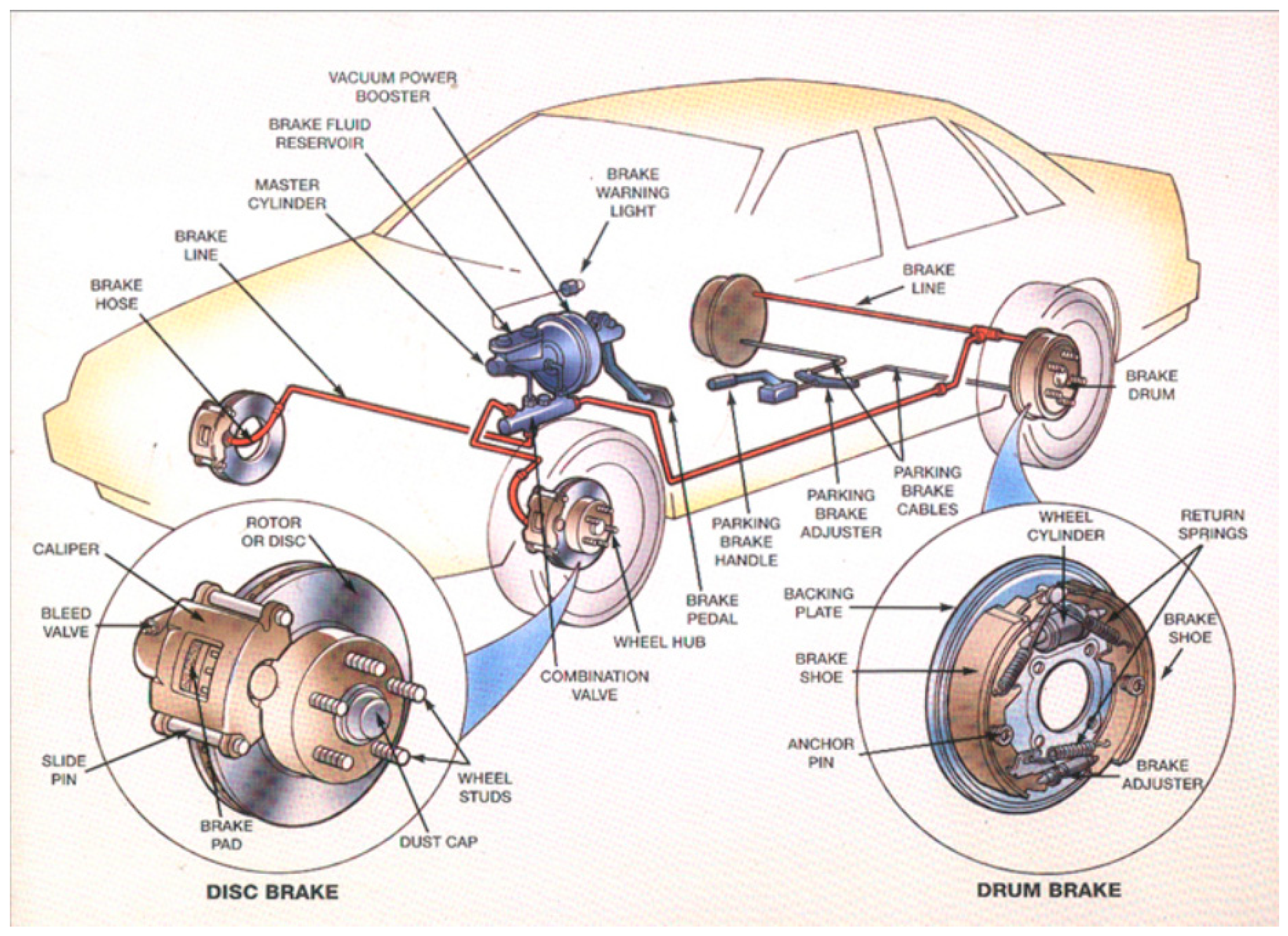
Automotive braking system (shown in
Figure 1) transforms the kinetic energy of the car, in object to decelerate or to stop it during a time interval of ∆t with an application of a braking moment T.
In order to reduce the rolling speed from
to a speed V with a deceleration a < 0, the driver must press the brake pedal to reduce the angular velocity of the wheels
, which results in a variation of the kinetic energy expressed as
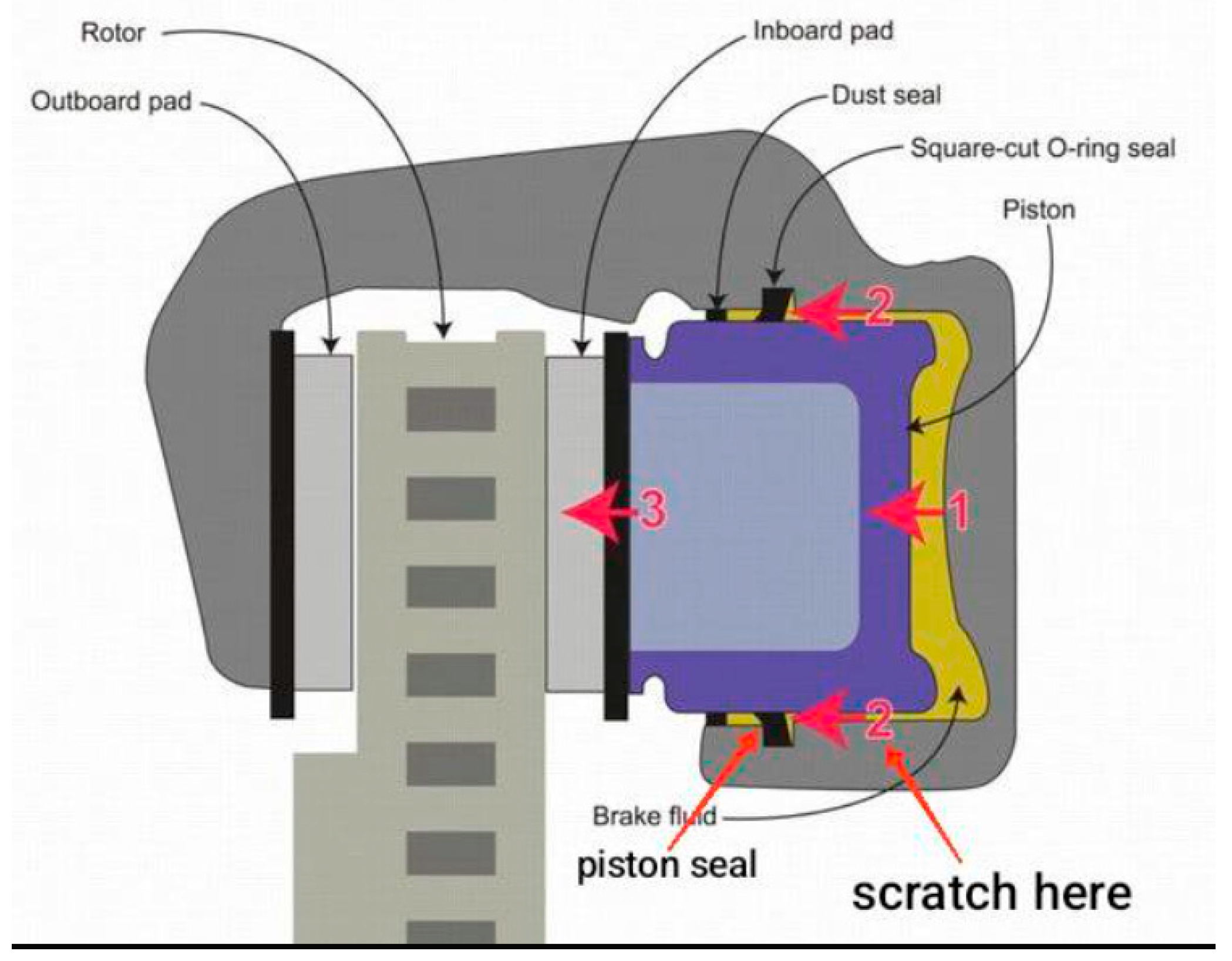
2.2. Braking Disc System
With the aim of slowing or stopping the vehicle within a specific time, the friction contact ensures the transformation of kinetic energy into heat energy. This is a high-performance braking system for vehicles with the wheel in contact with the ground.
As showing
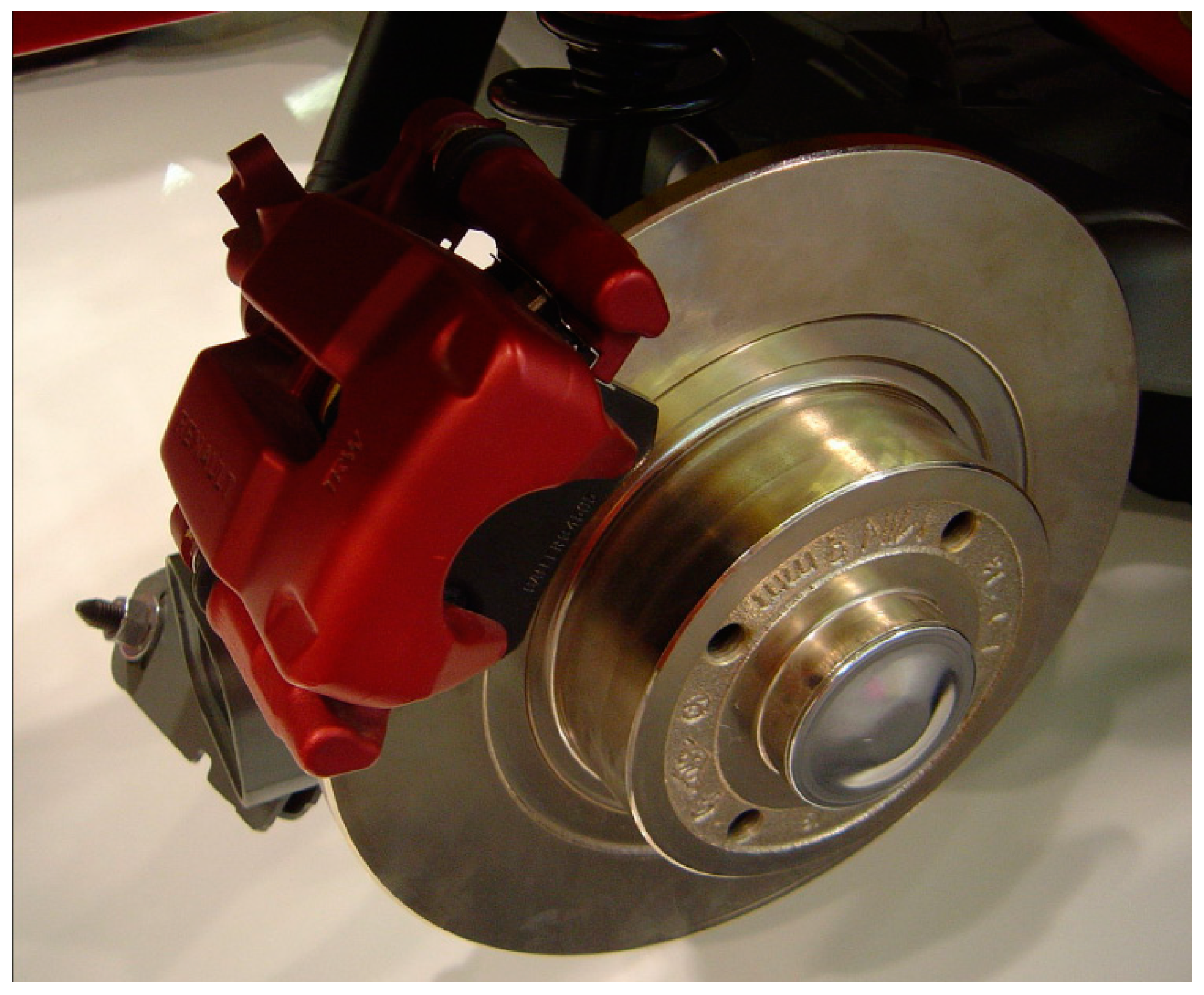
Figure 2, braking systems of vehicles using discs are generally an assembly of the following components:
- -
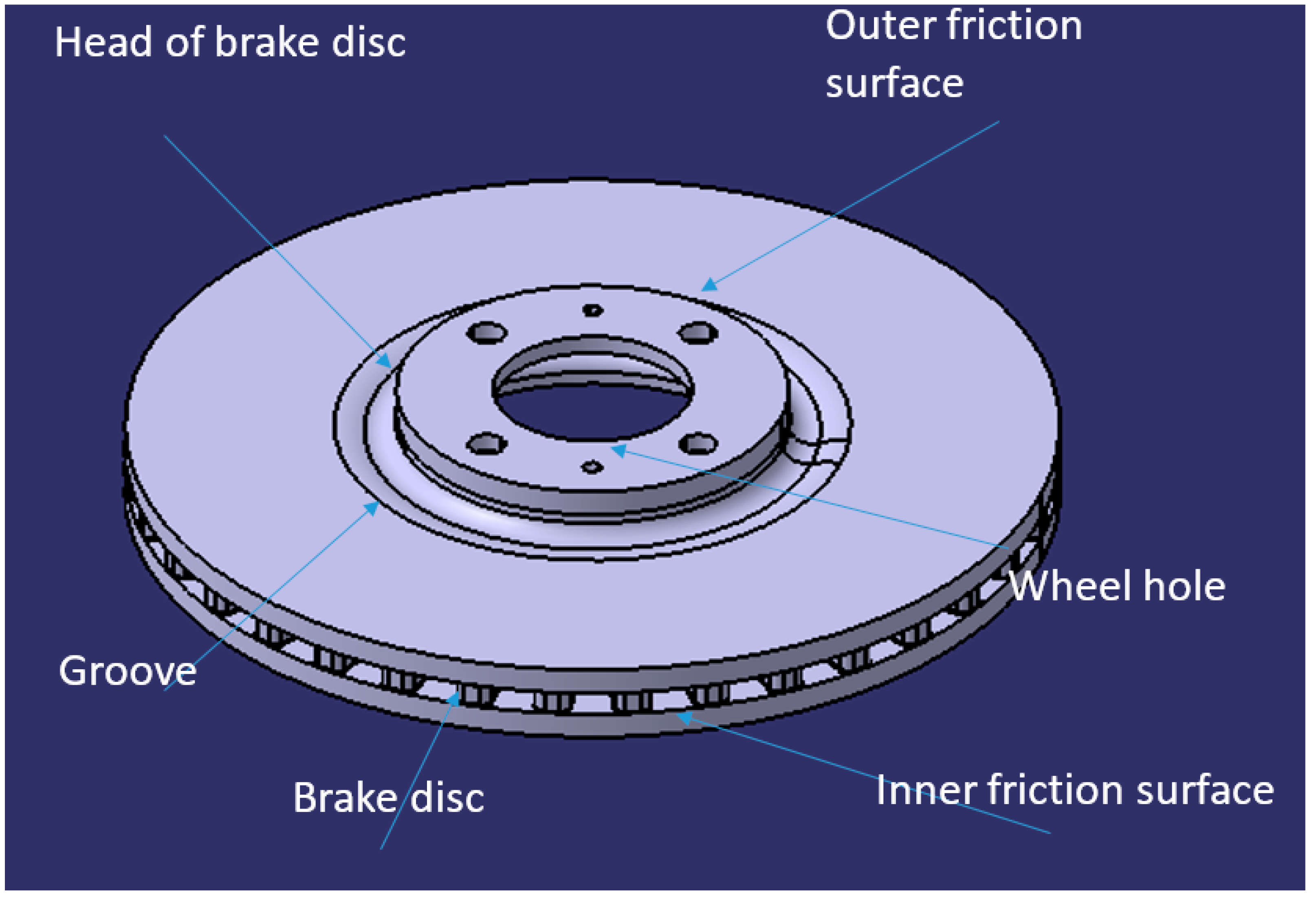
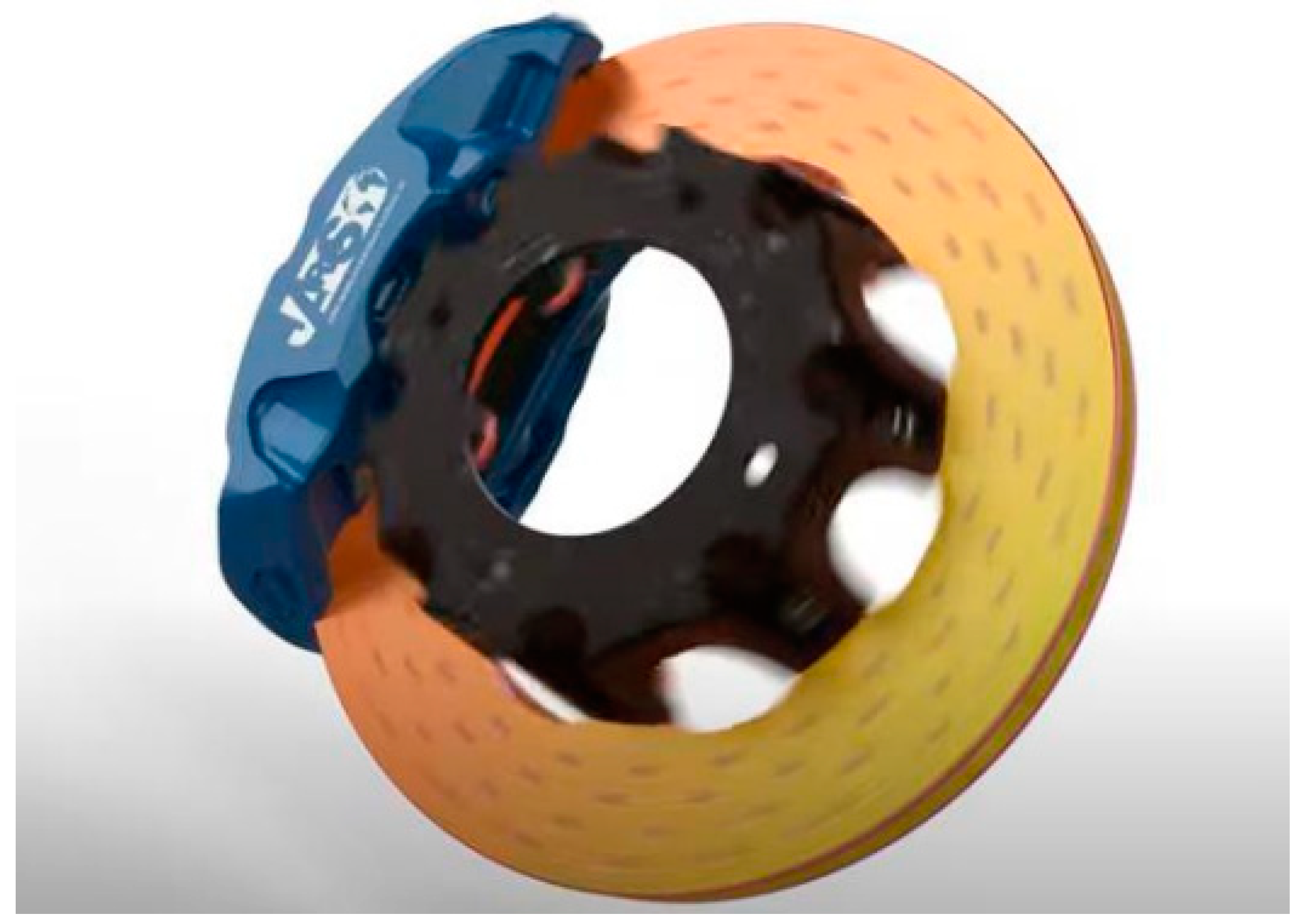
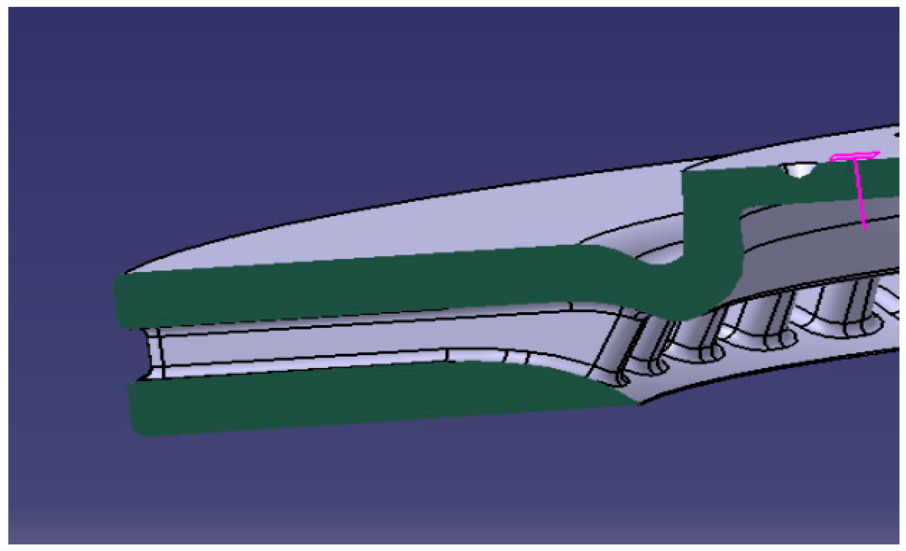
The brake disc (
Figure 3): The symmetric element linked to the wheel and clamped with a clamping hub. It receives the pressure from the pads on the inner and outer tracks and is clamped with a clamping hub and mounted on the wheel by the fixing holes located in the bowl head.
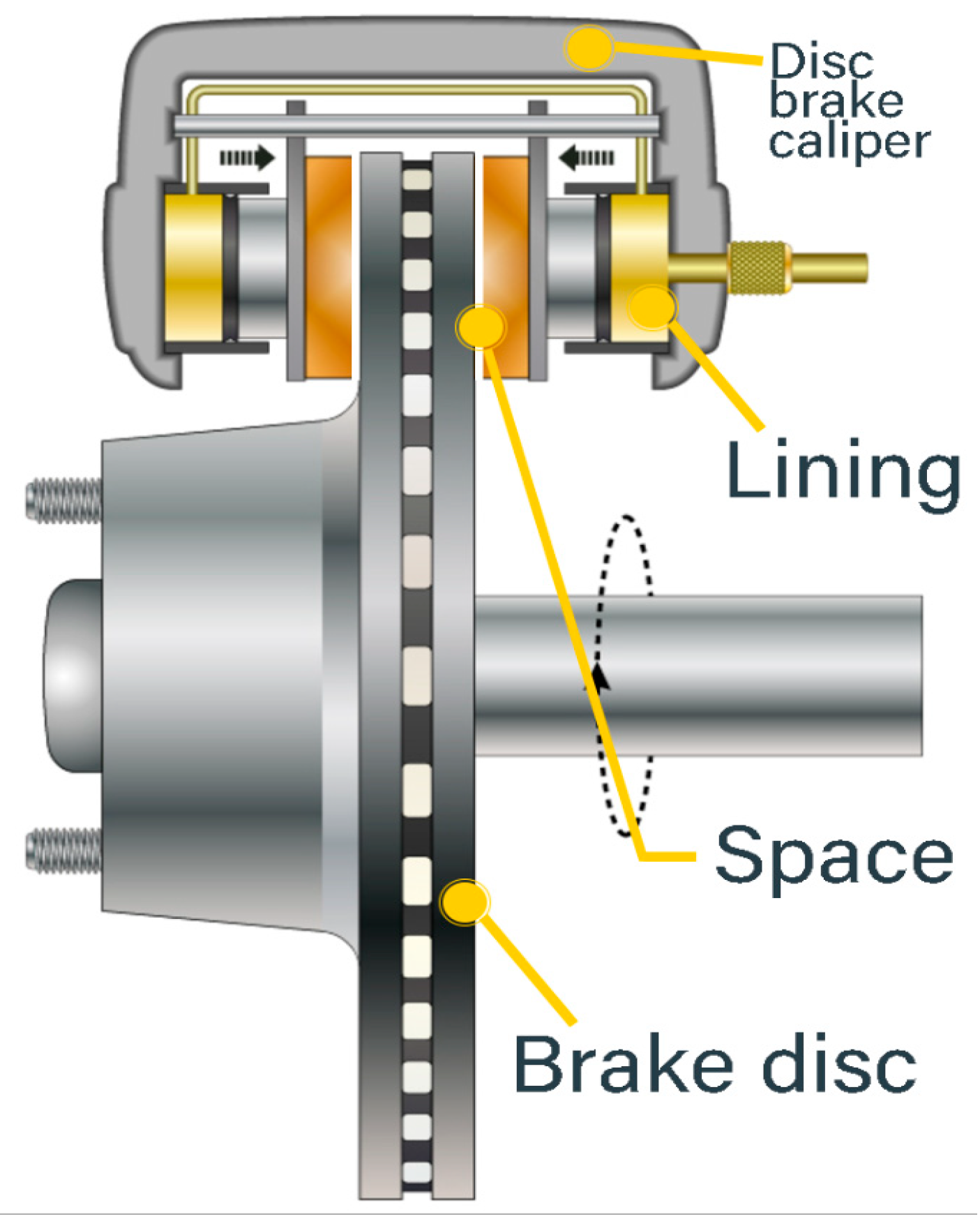
Pads (
Figure 4): each insert is composed of a gasket bonded to a support by gluing or riveting
- -
The caliper (
Figure 5): the component that covers the disc sector with its clevis shape, supports the pads and pistons and is attached to the axle via the knuckle. There are two types of calipers, fixed and floating.
The functionality of the fixed caliper is easy to understand. It consists of two pistons symmetrically fixed to the two sides of the caliper, which apply two pressures of the same intensity but in opposite directions to the brake pads without any movement of the caliper. Under the effect of friction, the contact between the brake pads and the disc transforms kinetic energy into calorific energy, braking the vehicle. In contrast, the sliding caliper is characterized by the movement of the pad carrier arm towards the brake disc in order to create braking contact, as shown in
Figure 6.
2.3. Braking Torque
When the brake disc receives pressure from the brake pads a normal force T will be applied on each track, the braking device receives a braking torque due to the tangential force F, the value of which is proportional to this pressure and the coefficient of friction (µ) and to the mean radius of the brake track (r). The braking torque gives rise to a braking force known as drag. In normal braking, once the brake pads are pressed against the brake tracks, the retarding force begins to increase until it reaches a constant value, which it maintains until the vehicle comes to a complete stop (
Figure 7). The retarding force then causes a reduction in speed, known as deceleration.
3. Thermomechanical Modelling of Automotive Brake Disc
Braking is achieved by dissipating kinetic energy through heat generation due to friction, by creating frictional contact between the tracks and the pad linings. This, in turn, raises the temperature of the tracks, which increases from 20 °C to over 700 °C suddenly.
This means that the temperature cannot be homogenized, even though there is a strong thermal gradient in the thickness of the tracks and in the circumferential direction.
As a result, the circular part of the track is very hot. Under this thermal effect, the binding energy begins to break down, which increases deformation and thermal expansion (
Figure 8).
The result is un-elastic, plastic, and possibly viscoelastic deformation.
The thermal gradient is distributed over:
- -
Surface gradient on contact tracks.
- -
Gradient in track thickness.
- -
Gradient in the disc groove.
In detail, this gradient maintains the cold zones and expands the hot zones, which creates a compression/tension cycle, during heating up and cooling down during braking/unbraking.
Braking is the dissipation of kinetic energy by heat generation due to friction; therefore, braking power will be the derivative of the work dissipated (kinetic energy theorem) with respect to time:
For good braking, the braking response must be uniform, and the front brake discs must dissipate the kinetic energy of the front axle in a uniform manner.
Brake discs must dissipate the kinetic energy of the front axle in an equitable manner. The same applies to the rear axle.
Let %p be the proportion of the front axle’s mass whose kinetic energy must be dissipated by the disc under study:
The main role of brake discs is to dissipate kinetic energy using heat generation due to friction. The amount of heat absorbed for each train equals the kinetic energy dissipated:
3.1. Thermal Modeling for Isotropic Material
Let v be the elementary volume, bounded by a surface located on one of the friction tracks (
Figure 9):
The heat equation describes the heat exchange between the disc and its environment:
where:
ρ: brake disc density (kg/m3)
Cp: mass heat capacity (J/kg K)
: unit vector of surface orientation
q: heat flux (W/m3)
k: thermal conductivity coefficient (W/K)
According to the Ostrogradski’s theorem:
Applying the null integral theorem, the obtained differential equation for calculating the temperature T(X, Y, Z) will be expressed as:
This equation is solved numerically using the finite element method, where the boundary and initial heat conditions are defined by:
The heat transfer governing equation will be projected using the Galerkin formulation and the Lagrange basis functions under the following expression:
The divergence of gradient can be decomposed by Ostrogradski decomposition so that the final format of the equation will be:
3.2. Finite Element Discretization for Thermal Modeling
The solution of differential equations is very difficult analytically. FEM divides the solid under study into a set of elements connected by nodes, in an operation called meshing, and this operation is used to decompose the convex interval of the integration in order to establish the following elementary matrices and vectors:
- -
The thermal capacity matrix :
- -
The thermal conductivity matrix
- -
The elementary flux vector .
The temperature field T(x,y,z) is projected onto the Lagrange basis functions using polynomial interpolation, and expressed as:
This implies:
where [B] is a spatial operator written as:
with:
All the elemental matrices must be assembled in order to build the global matrices and move on to the final stage of solving the problem. The nodal expression of these matrices is written as:
with:
- -
[C]: heat capacity matrix (J/K)
- -
[K]: thermal conductivity matrix (W/K)
- -
{F}: nodal flux vector (W)
- -
{T}: nodal temperature vector (K)
3.3. Mechanical Study of Contact Between Disc and Pads
The study of the contact between the disc and the pads unravels the thermomechanical phenomena that occur at this level, including the friction work induced when normal pressure is applied in the presence of the disc’s rotational speed and the coefficient of friction between the disc and the pads. A surface state that allows friction between the disc and the pads, giving rise to a heat flow, can be expressed as:
where:
- -
µ is the coefficient of friction.
- -
V is the speed of rotation.
- -
P is the pressure applied by the pads.
The article [
10] proposes a static structural simulation coupled with a thermal study under Ansys R1 2020, this simulation uses as an input data the maximum temperature values on tracks, while the current paper proposes a thermomechanical coupling method but with a transient thermal study with a variable heat flow depending on the variation of the wheel rotation speed during 45 s before moving on to import the results into a static structural calculation for the purpose of calculating the equivalent von Mises stress considered as the criterion for the validation of the geometry and material.
3.4. Expression of Pressure Required for Automotive Braking
For a stopping time
, the kinetic energy theorem can be used to deduce the mechanical friction work required to cool down the vehicle. When this energy is dissipated as a function of the percentage of mass distributed along the vehicle, the variation of kinetic energy for the front axle is expressed as:
with a constant deceleration, this velocity takes a linear behavior, so that the precedent equation can be also expressed as:
So that the pressure applied on the disc can be written like:
with:
- -
θ: braking angle (Rad).
- -
: the contact surface of a pad ().
- -
: disc radius (m).
- -
: pressure applied by the two pads (MPa).
- -
: initial speed of the car (m/s).
- -
M: mass of the car (Kg).
- -
: pressure applied by one pad on the disc (MPa).
3.5. The Heat Flow Generated by the Brake Disc When the Pads Are Pressed Down
The heat flux generated by the brake disc
, and that generated by the pads
are dependent on the characteristics of each component. The total exchange flux q is the sum of the two fluxes. Therefore, the expression of the relative energy γ is written in the following form:
where,
are, respectively, the heat capacity, the density, and the thermal conductivity of the pads, while
, are those of the disc.
3.6. Thermomechanical Strain
The brake disc is subjected to mechanical and thermal solicitations, which means that the strain will be both thermal and mechanical. The elastic range of the strain is expressed by:
where:
- -
: the thermal deformation vector.
- -
: the elastic deformation vector.
- -
{ε}: the thermoelastic deformation vector.
- -
[A]: the flexibility matrix (1/MPa).
- -
: the coefficient of thermal expansion for an isotropic medium (1/K).
- -
{σ}: the vector of applied mechanical stresses (MPa).
- -
∆T: thermal variation (K).
3.7. Construction of a Numerical Validation Model for the Thermomechanical Calculation of Automotive Brake Discs
Instead of using a dynamic calculation to model braking, the theoretical expression of the formula for heat flow caused by friction makes it easy to replace this CPU-intensive calculation with a transient thermal calculation where the thermal flow is represented by its theoretical function, dependent on the variation of the rotational speed due to deceleration, and then couple the transient thermal results with the mechanical conditions in a static structural calculation.
The table below outlines the thermal and mechanical tests to be conducted using Ansys Workbench R1 2020, followed by the collection of technical data. Begin by performing a thermal calculation over a period of 45 seconds [
11], applying the heat flux generated by friction while accounting for convective heat exchange with the air over time. Subsequently, visualize the thermal field in the results.
As described in
Table 1, the results will be coupled directly with the static analysis under the same calculation conditions (time of start, time step, and time of end).
4. Material Selection Method
Steel and cast iron are the materials most used in brake discs. Austenitic stainless steels are highly ductile and resilient materials, so they can withstand high temperatures.
High-carbon cast irons, on the other hand, are able to absorb heat without much impact on mechanical properties, thanks to carbon’s ability to withstand thermal stresses and high mechanical strength.
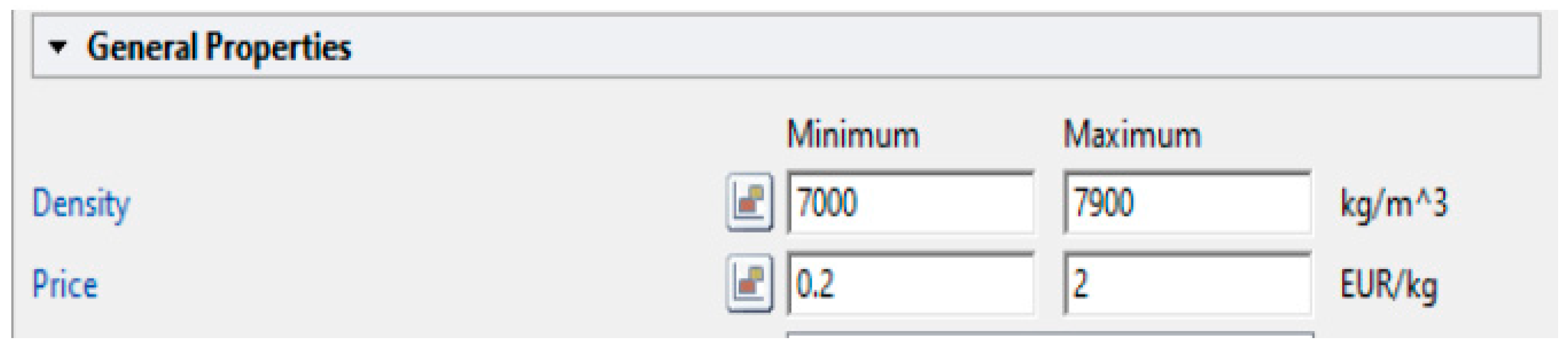
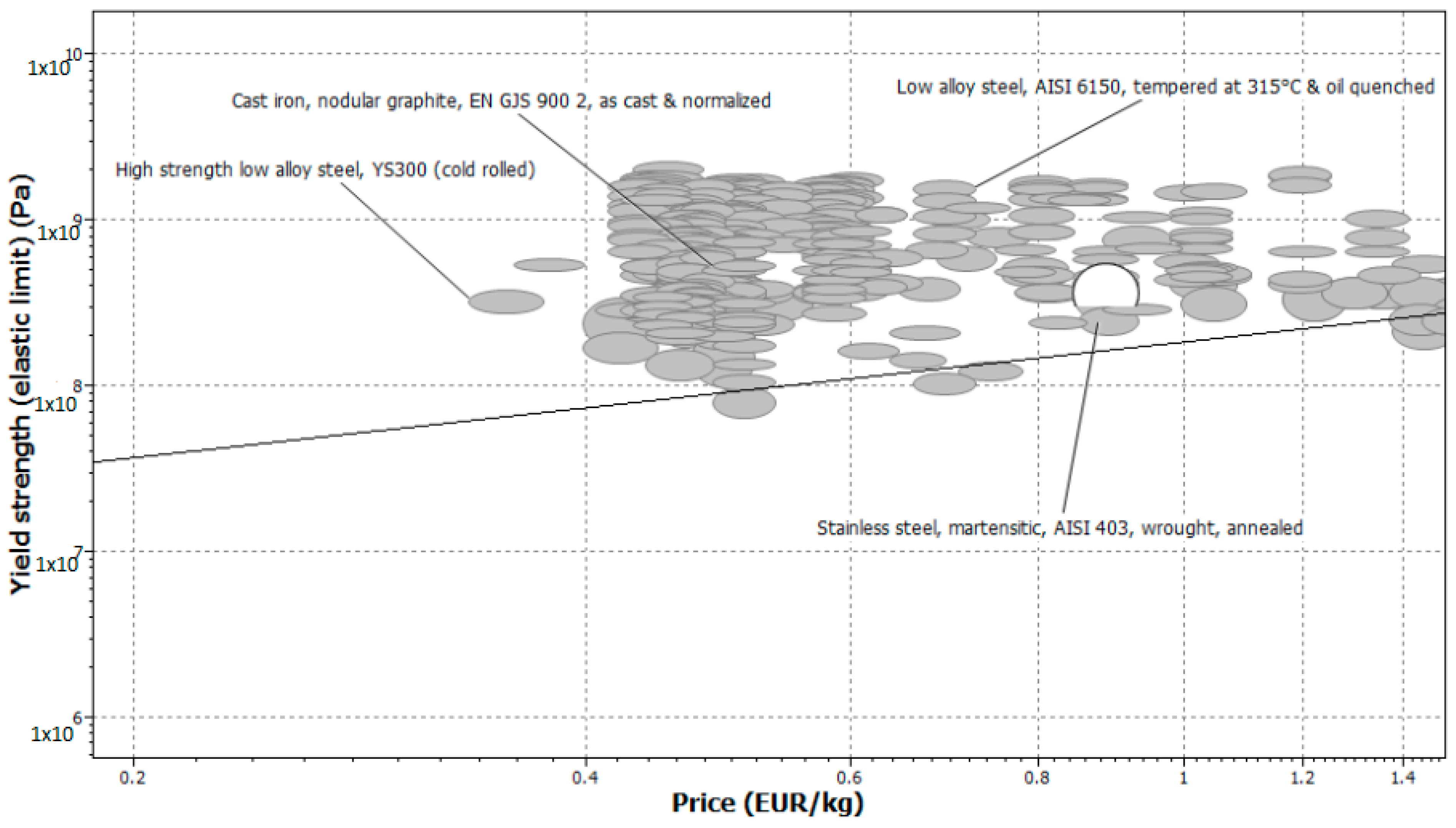
4.1. Searching for Materials with CES Edu Pack
Depending on market availability, Ashby’s method can be used to research materials for carbon–iron alloys based on the criteria listed in
Table 2.
In the CES Edu Pack, the characteristics filter is used to find the most optimal package of materials in terms of cost and performance.
Referring to [
12,
13], cast iron is the most used material in automotive brake discs due to its high capacity of heat absorption while guarding the same mechanical characteristics. The following table represents the most optimal materials in terms of their price and weight (
Table 3).
4.2. Used Material
The allocation of materials to the front and rear axle automotive parts is made in accordance with the project’s target mass and price. The price multiplied by the mass density is used to calculate the volume price that will be used to classify the materials from least to most expensive, the
Table 4 presents a classification of qualified materials to be used in brake disc basing on the price per volume.
Even though it is not the cheapest material, EN GLJ 250 is widely used in the manufacture of automotive brake discs because of its combination of properties, such as wear resistance, heat dissipation, impact resistance, and ease of manufacture. It is therefore an optimal choice for many types of vehicles, offering a good compromise between performance, durability, and production cost [
14].
5. Numerical Simulation and Discussion
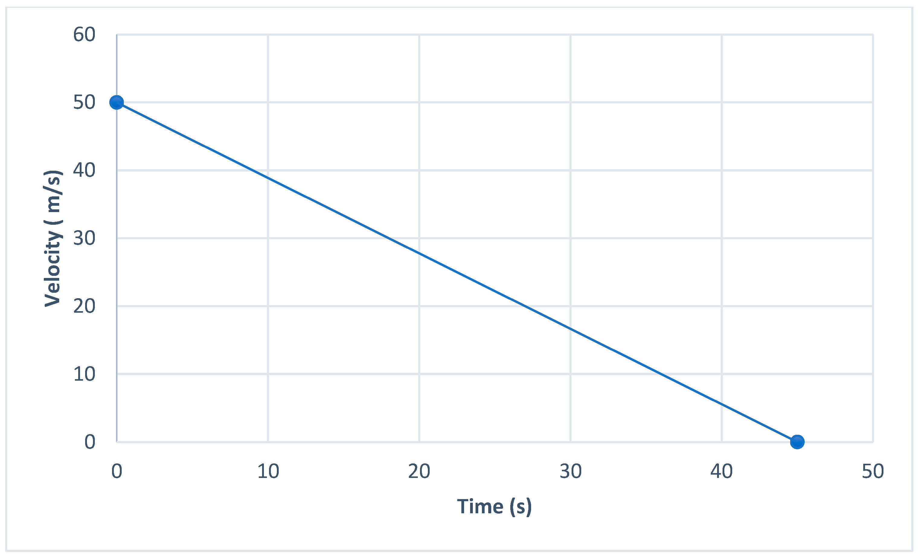
Many automotive manufacturers have investigated to make calculations more efficient and similar to reality because of the difference between the animations and physical values. Thermomechanical coupling is one of the most interesting approaches for testing the behavior of components when facing high stress and temperature. This paper proposes to use heat flow with theoretical formulation with a constant deceleration for 45 s. The following graph describes the variation of the speed during braking time (
Figure 15).
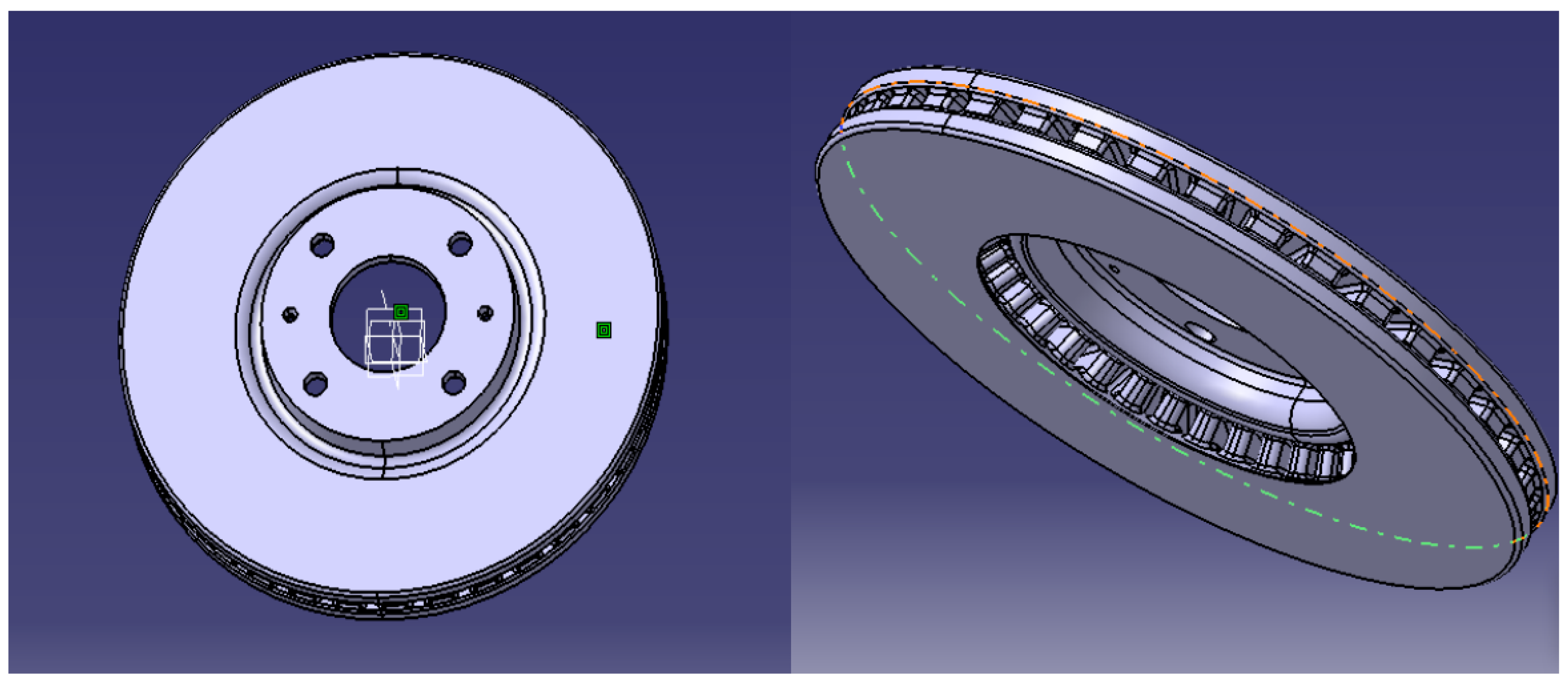
5.1. Geometry and Material’s Input Data
In this study, a ventilated internal track brake disc has been used to test the efficiency of the adopted approach because this type of brake disc is frequently used due to the cooling of runways through the airflow entering the ventilation pallets (
Figure 16,
Figure 17 and
Figure 18).
The selected material for this study is EN GLJ 250, which refers to the “grade of gray cast iron” that conforms to European standard EN 1561:2010. The key characteristics of this material are:
Minimum tensile strength: 250 MPa (Mega Pascals)
Minimum yield strength: typically around 200 MPa
Elastic stress for EN GLJ 250: 162–195 MPa
Elongation at break: around 1.5–3%
Brinell hardness: generally around 190–240 HB (depending on the specific cast form)
Composition:
- -
Carbon content: 2.8–3.3%
- -
Silicon content: 1.7–2.5%
- -
Manganese content: 0.6–1.0%
- -
Phosphorus and sulfur: typically kept low to prevent brittleness.
This material is also distinguished by:
Good castability: the material’s composition and structure make it easy to cast into complex shapes, making it ideal for components like brake discs.
Wear resistance: it has good wear resistance, which is essential for components that experience friction, such as brake discs.
Heat dissipation: due to its structure, it is capable of dissipating heat effectively, which is vital for high-performance components like brake discs that operate under high temperatures.
Ductility and impact resistance: while not as ductile as some other materials, gray cast iron materials like EN GLJ250 have reasonable impact resistance, which is necessary to withstand sudden forces during braking.
Corrosion resistance: gray cast iron offers moderate resistance to corrosion, though it can still degrade if exposed to certain harsh environments without proper coating.
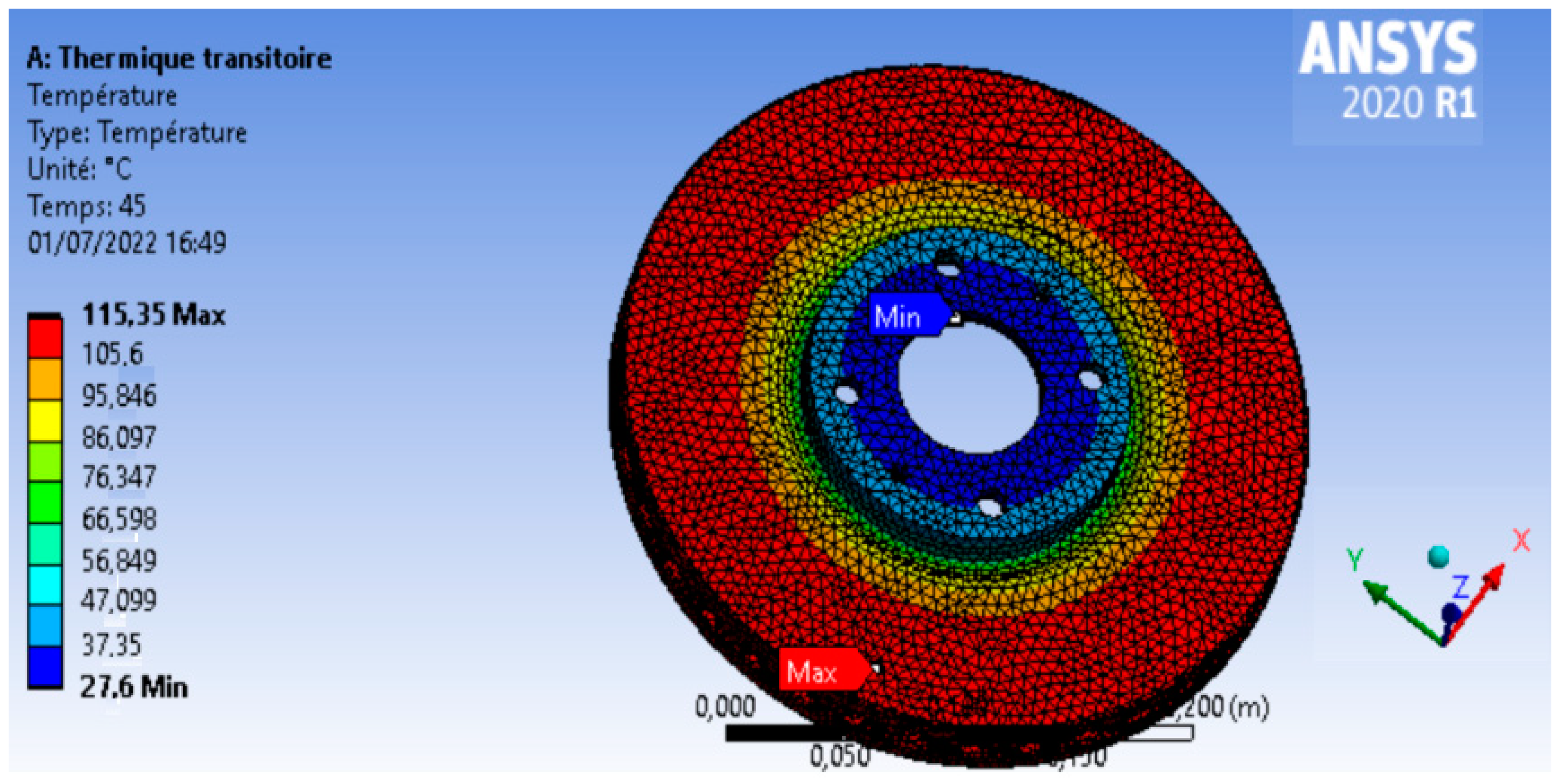
5.2. Thermal Simulation and Results
As shown in
Table 5, the transient thermal calculation is the first calculation to be carried out since it enables us to visualize the thermal behavior of the disc under the application of a heat flow deduced from the friction between the disc and the pads for 45 s with a deceleration of 1.111 m/s.
Following the mesh specifications described in
Table 3, the tetra mesh used is made up of
162,878 nodes and
97,148 elements with
a 90% edge length between 6 mm and 8 mm [
15,
16].
The running of the calculation provides results that are very close to reality, as the temperature reaches a maximum value in the tracks equal to 115 °C, which indicates that the thermal gradient is normal according to the volume of the brake disc (
Figure 19).
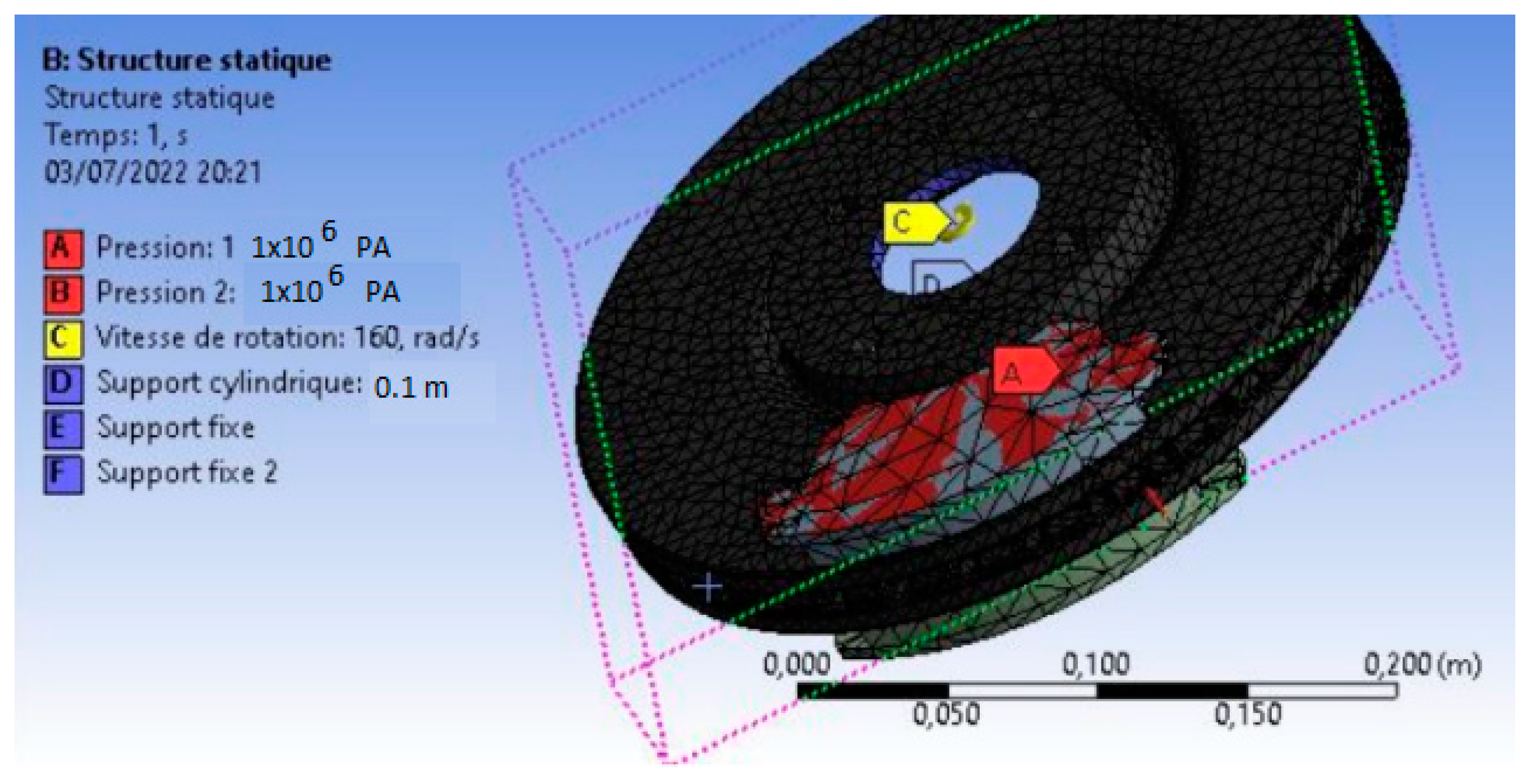
5.3. Thermomechanical Coupling Simulation
Thermomechanical coupling of brake discs allows us to model the interaction between thermal and mechanical loads, where thermal effects influence the mechanical behavior of the disc. This technique is also applicable to the study of engine components, as temperature changes induce thermal expansion, which modifies material properties such as stiffness and strength. Therefore, understanding thermomechanical coupling is essential for accurately predicting the performance and durability of materials under real-life operating conditions.
A rotational speed of 160 rad/s was applied at
t = 0 s, with the disc fixed at its mounting points. Each brake pad exerts a normal pressure of 1 MPa, and frictional contact is present with a coefficient of friction of 0.2, as shown in the following figure (
Figure 20).
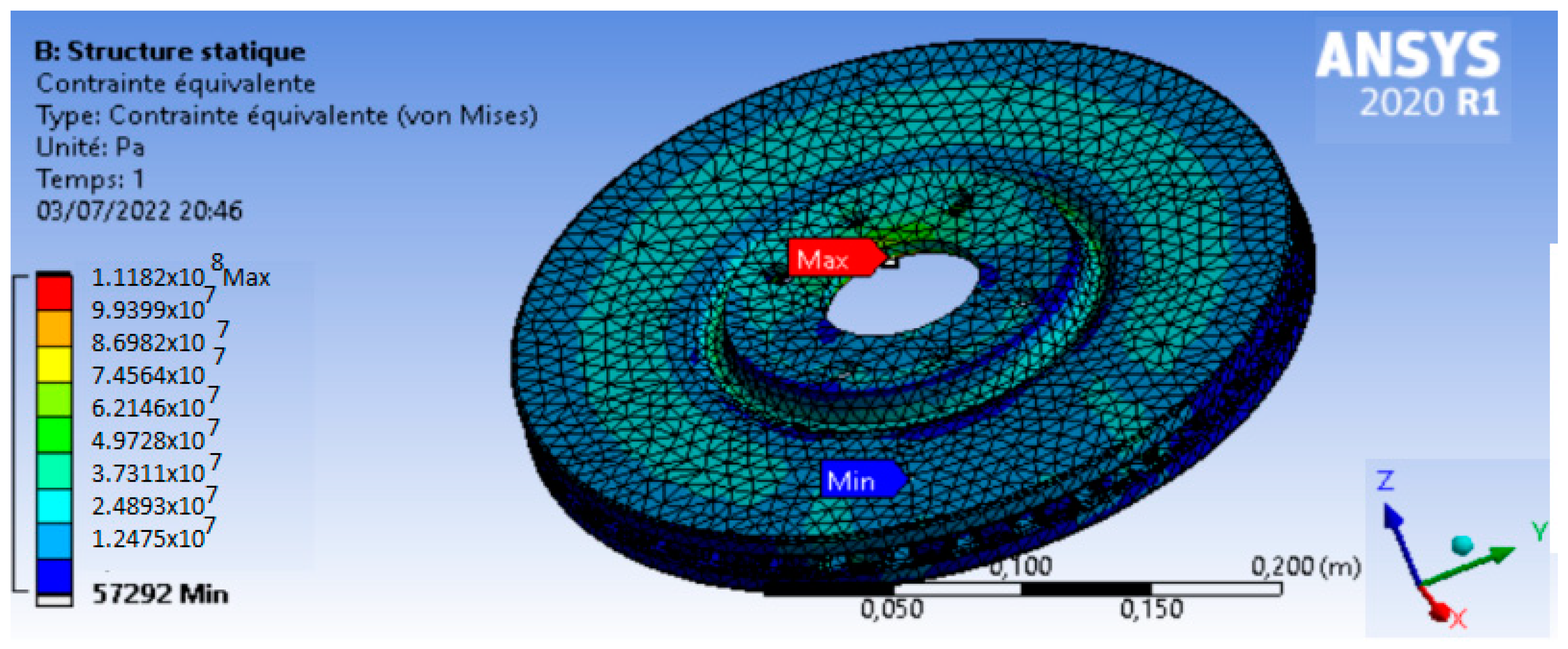
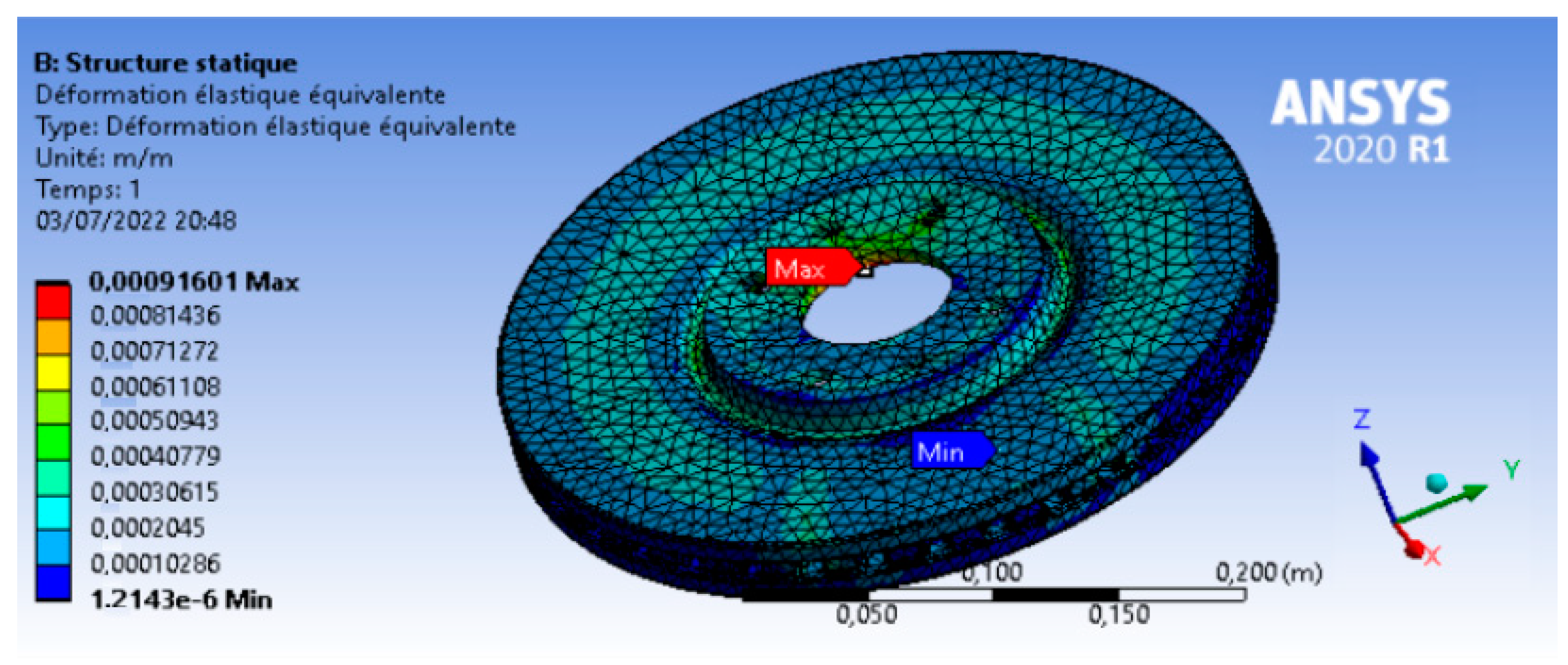
Figure 21 and
Figure 22 show the results of the thermomechanical simulation carried out to analyze the behavior of the brake disc under braking conditions. They show the evolution of von Mises stress and deformation in the disc during the process, highlighting areas of stress concentration and variations in deformation as a function of disc volume.
As shown in the previous figures, the maximum stress equivalent equals 111,82 MPA while the minimum yield elastic stress of the material EN GLJ 250 is 162 MPa. Therefore, for a car with a target mass of 1000 Kg, the studied brake disc can be used with a high security factor.
Based on the results shown in
Figure 19 and
Figure 21, the thermomechanical coupling method demonstrated the high performance of the EN GLJ 250 material when facing thermomechanical loading, due to the high thermal capacity of carbon and the invariance of the mechanical properties of this component. On the other hand, it is remarkable that the proposed coupling methodology is very flexible and fast.
6. Conclusions
This paper’s main objective was to carefully investigate and compare the performance of the proposed protocol to the state of the art for improving the simulation of brake discs of cast iron materials and making it more realistic and to introduce a simple method for selecting materials during the simulation phase.
Moreover, it is critical to recognize the dominating trend in numerical simulations of automotive components, which primarily concern parts related to security. Thus, we started with the creation of governing equations for thermal transfer under braking, before coupling the thermal study with the structural static one.
Through this approach, we have been able to combine the transient thermal and structural studies using a very powerful tool like Ansys. This software is one of the best for simulation coupling due to the dashboard of projects implemented in Ansys called “Workbench”.
We consider the proposed idea of this paper one of the best for brake disc numerical calculations for several reasons:
- -
The coupling of a transient thermal calculation with a static structural analysis is more optimal than dynamic calculation, which relies on the generation of temperature due to the friction between the pads and the disc. This is because dynamic calculations require a very demanding explicit dynamic model on the CPU [
17,
18]. Moreover, the proposed approach increases the safety margin, making it more optimal for performance engineers to validate a configuration that is more resistant and durable.
- -
The approach followed in this article enhances those used in previous articles [
4,
8,
19,
20,
21,
22] by introducing a theoretical calculation of the heat flux induced in the tracks of the disc where the heat flow varies depending on the change in the vehicle’s rolling speed so that the results can be validated automatically due to the efficiency of those in the cited papers.
- -
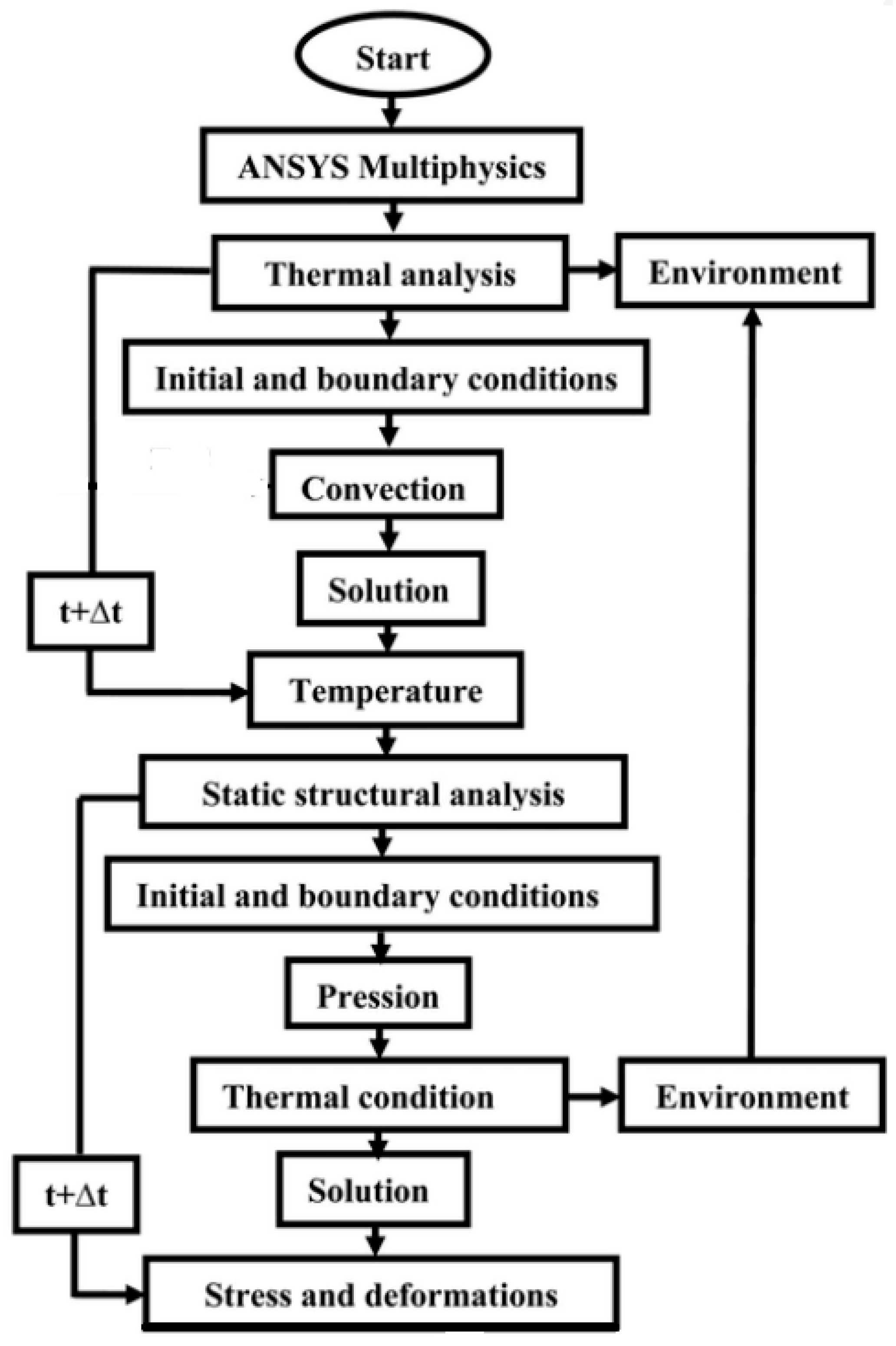
This method described in
Figure 23 makes the simulation more realistic and allows engineers to use the same numerical model for fatigue analysis without needing to re-model.
- -
The addition of the Ashby method for selecting materials for brake discs allows for optimization in terms of cost and physical characteristics of the applied material, enabling the design of a durable brake disc with minimal cost [
23].
- -
The proposed approach is directly accessible for use in a fatigue study or crack propagation analysis using the X-FEM method. It is only necessary to locate the areas that satisfy the cracking conditions, re-mesh around the crack using the Ansys Smart Crack tool, and finally restart the calculation to post-process the SIFs in modes 1, 2, and 3 [
5,
6,
24,
25,
26,
27,
28].
While this method is a useful tool for predicting brake disc thermomechanical behavior under the described loading conditions, it has some key limitations when applied to more complex situations. These limitations include its inability to model progressive damage or incorporate environmental and fatigue effects. Therefore, it is important to consider complementary methods like X-FEM or X-IGA to predict the life cycle of the component [
29,
30,
31,
32].
In terms of future work, we plan to explore the extended finite elements method (X-FEM) to perform thermal–structural simulations, aiming to demonstrate its potential to deliver more accurate results, especially the stress intensity factor for modes 1, 2, and 3.
Author Contributions
Conceptualization, M.B.G., A.H. and A.E.K.; Methodology, M.B.G., A.H., A.E.K. and B.H.; Software, M.B.G. and A.H.; Validation, A.E.K., B.H., S.V. and M.L.S.; Formal analysis M.B.G. and S.V.; Investigation, M.B.G. and A.H.; Resources, A.E.K. and M.L.S.; Data curation, M.B.G.; Writing—original draft, M.B.G., A.H. and A.E.K.; Writing—review & editing, S.V. and M.L.S.; Visualization, A.E.K., S.V. and M.L.S.; Supervision, A.E.K., S.V. and M.L.S.; Project administration, A.E.K.; Funding acquisition, S.V. and M.L.S. All authors have read and agreed to the published version of the manuscript.
Funding
APC was funded by Transylvania University of Brasov, Grant Number HBS 1934/2-2024.
Data Availability Statement
The original contributions presented in the study are included in the article, further inquiries can be directed to the corresponding author.
Conflicts of Interest
The authors declare no conflict of interest.
References
- Luo, C.; Li, C.; Wan, X.; Zhao, Z. Convective Heat Transfer Coefficient of Insulation Paper–Oil Contact Surface of Transformer Vertical Oil Channel. Coatings 2023, 13, 81. [Google Scholar] [CrossRef]
- Libonati, F.; Buehler, M. Advanced Structural Materials by Bioinspiration. Adv. Eng. Mater. 2017, 19, 1600787. [Google Scholar] [CrossRef]
- Carlson, J.D.; Bhardwaj, R.; Phelan, P.; Kaloush, K.; Golden, J.S. Determining thermal conductivity of paving materials using cylindrical sample geometry. J. Mater. Civ. Eng. 2010, 22, 186–195. [Google Scholar] [CrossRef]
- Belhocine, A.; Afzal, A. A predictive tool to evaluate braking system performance using a fully coupled thermo-mechanical finite element model. Int. J. Interact. Des. Manuf. 2020, 14, 225–253. [Google Scholar] [CrossRef]
- Gouzi, M.B.; El Fakkoussi, S.; Khalfi, A.E.; Vlase, S.; Scutaru, M.L. Numerical Study of an Automotive Crash Box in Carbon Fiber Reinforced Polymer Material Using Chang Failure Criteria. Mathematics 2024, 12, 3673. [Google Scholar] [CrossRef]
- Berrada-Gouzi, M.; El Khalfi, A.; Vase, S.; Scutaru, M.L. X-IGA Used for Orthotropic Material Crack Growth. Materials 2024, 17, 3830. [Google Scholar] [CrossRef]
- Rathin, S.; Chinmay, S.; Swapnil, T. Design and analysis of a hydraulic Brake caliper. Int. J. Mech. Eng. Technol. 2017, 8, 33–41. [Google Scholar]
- Lü, H.; Dejie, Y. Brake squeal reduction of vehicle disc brake system with interval parameters by uncertain optimization. J. Sound Vib. 2014, 333, 7313–7325. [Google Scholar] [CrossRef]
- Baharin, M.S.; Shahrum, A.; Salvinder, S.; Khairul, F. Computational fatigue failure analysis of magnesium alloy core structure inside the metal sandwich panels under constant spectrum loadings. Eng. Fail. Anal. 2022, 139, 106194. [Google Scholar] [CrossRef]
- Wang, C.; Wang, S.; Jin, H.; Huo, H.; Xu, H.; Chen, Z. Thermal-mechanical coupling analysis and optimization of mine hoist brake disc. Adv. Mech. Eng. 2022, 14, 16878132221106297. [Google Scholar] [CrossRef]
- Jiang, J.; Ketabdari, M.; Crispino, M.; Toraldo, E. Estimating vehicle braking distance over wet and rutted pavement surface through back-propagation neural network. Results Eng. 2024, 21, 101686. [Google Scholar] [CrossRef]
- Matsushita, T.; Ghassemali, E.; Saro, A.G.; Elmquist, L.; Jarfors, A.E.W. On Thermal Expansion and Density of CGI and SGI Cast Irons. Metals 2015, 5, 1000–1019. [Google Scholar] [CrossRef]
- Nayak, U.P.; Guitar, M.A.; Mücklich, F. A Comparative Study on the Influence of Chromium on the Phase Fraction and Elemental Distribution in As-Cast High Chromium Cast Irons: Simulation vs Experimentation. Metals 2020, 10, 30. [Google Scholar] [CrossRef]
- Pevec, M.; Oder, G.; Potrč, I.; Šraml, M. Elevated temperature low cycle fatigue of grey cast iron used for automotive brake discs. Eng. Fail. Anal. 2014, 42, 221–230. [Google Scholar] [CrossRef]
- Gagné, M.; Therriault, D. Lightning strike protection of composites. Prog. Aerosp. Sci. 2014, 64, 1–16. [Google Scholar] [CrossRef]
- Thierry, C.; Hugues, D.; Richard, D. Parallel meshing and remeshing. Appl. Math. Model. 2000, 25, 153–175. [Google Scholar]
- Sau, S.K.; Pulinat, K.G.; Moss, P.N.; Ranjeet, P.; Prabu, S.S. A comparative study on the thermal and dynamic analysis of a disc brake using Ansys. Mater. Today Proc. 2022, 65 Pt 8, 3714–3723. [Google Scholar]
- Shahril, A.S.; Razali, J.; Daut, J. Structural analysis of brake disc using dynamic simulation. ARPN J. Eng. Appl. Sci. 2015, 10, 7805–7808. [Google Scholar]
- Alperen, Y.; Sertac, C. Multi objective optimization of a micro-channel heat sink through genetic algorithm. Int. J. Heat Mass Transf. 2019, 146, 118847. [Google Scholar] [CrossRef]
- Maniana, M.; Chaqouri, M.; Benkachcha, S.; Tajamouati, A. Thermomechanical Study of a Disc Brake. In Proceedings of the 2023 3rd International Conference on Innovative Research in Applied Science, Engineering and Technology (IRASET), Mohammedia, Morocco, 18–19 May 2023; pp. 1–4. [Google Scholar]
- Grzes, P.; Kuciej, M. Coupled thermomechanical FE model of a railway disc brake for friction material wear calculations. Wear 2023, 530, 205049. [Google Scholar] [CrossRef]
- Belhocine, A.; Bouchetara, M. Investigation of temperature and thermal stress in ventilated disc brake based on 3D thermomechanical coupling model. Ain Shams Eng. J. 2013, 4, 475–483. [Google Scholar] [CrossRef]
- Yevtushenko, A.A.; Grzes, P. Initial Selection of Disc Brake Pads Material based on the Temperature Mode. Materials 2020, 13, 822. [Google Scholar] [CrossRef]
- Montassir, S.; Moustabchir, H.; El Khalfi, A.; Vlase, S.; Scutaru, M.L. Numerical Study of Crack Prediction and Growth in Automotive Wheel Rims. Materials 2024, 17, 1020. [Google Scholar] [CrossRef] [PubMed]
- Barros, F.B.; Silva, R. Extended isogeometric analysis: A two-scale coupling FEM/IGA for 2D elastic fracture problems. Comput. Mech. 2023, 73, 639–665. [Google Scholar]
- Nie, D.; Zhang, X. Engineering Fracture Mechanics XFEM with partial Heaviside function enrichment for fracture analysis. Eng. Fract. Mech. 2021, 241, 107375. [Google Scholar]
- Geniaut, S.; Galenne, E. A simple method for crack growth in mixed mode with X-FEM. Int. J. Solids Struct. 2012, 49, 2094–2106. [Google Scholar] [CrossRef]
- Montassir, S.; Moustabchir, H.; El Khalfi, A.; Scutaru, M.L.; Vlase, S. Fracture Modelling of a Cracked Pressurized Cylindrical Structure by Using Extended Iso-Geometric Analysis (X-IGA). Mathematics 2021, 194, 2990. [Google Scholar] [CrossRef]
- Abdulnaser, A.; Yahya, F. 3D modelling of fatigue crack growth and life predictions using ANSYS. Ain Shams Eng. J. 2022, 13, 101636. [Google Scholar]
- Bai, B.; Ci, H.; Lei, H.; Cui, Y. A local integral-generalized finite difference method with mesh-meshless duality and its application. Eng. Anal. Bound. Elem. 2022, 139, 14–39. [Google Scholar] [CrossRef]
- Moes, N.; Belytschko, T. X-FEM, de nouvelles frontières pour les éléments finis. Eur. J. Comput. Mech. 2012, 11, 305–318. [Google Scholar] [CrossRef]
- Yakoubi, K.; Montassir, S.; Moustabchir, H.; El Khalfi, A.; Pruncu, C.I.; Arbaoui, J.; Farooq, M. An Extended Finite 561 Element Method (XFEM) Study on the Elastic T-Stress Evaluations for a Notch in a Pipe Steel Exposed to Internal Pressure. Mathematics 2021, 9, 507. [Google Scholar] [CrossRef]
Figure 1.
Automotive braking system.
Figure 1.
Automotive braking system.
Figure 2.
Brake disc and caliper assembly.
Figure 2.
Brake disc and caliper assembly.
Figure 6.
Floating caliper representation.
Figure 6.
Floating caliper representation.
Figure 7.
Braking torque representation.
Figure 7.
Braking torque representation.
Figure 8.
Thermomechanical phenomenon of brake discs.
Figure 8.
Thermomechanical phenomenon of brake discs.
Figure 9.
Elementary field flow.
Figure 9.
Elementary field flow.
Figure 10.
General properties.
Figure 10.
General properties.
Figure 11.
Thermal properties.
Figure 11.
Thermal properties.
Figure 12.
Mechanical properties.
Figure 12.
Mechanical properties.
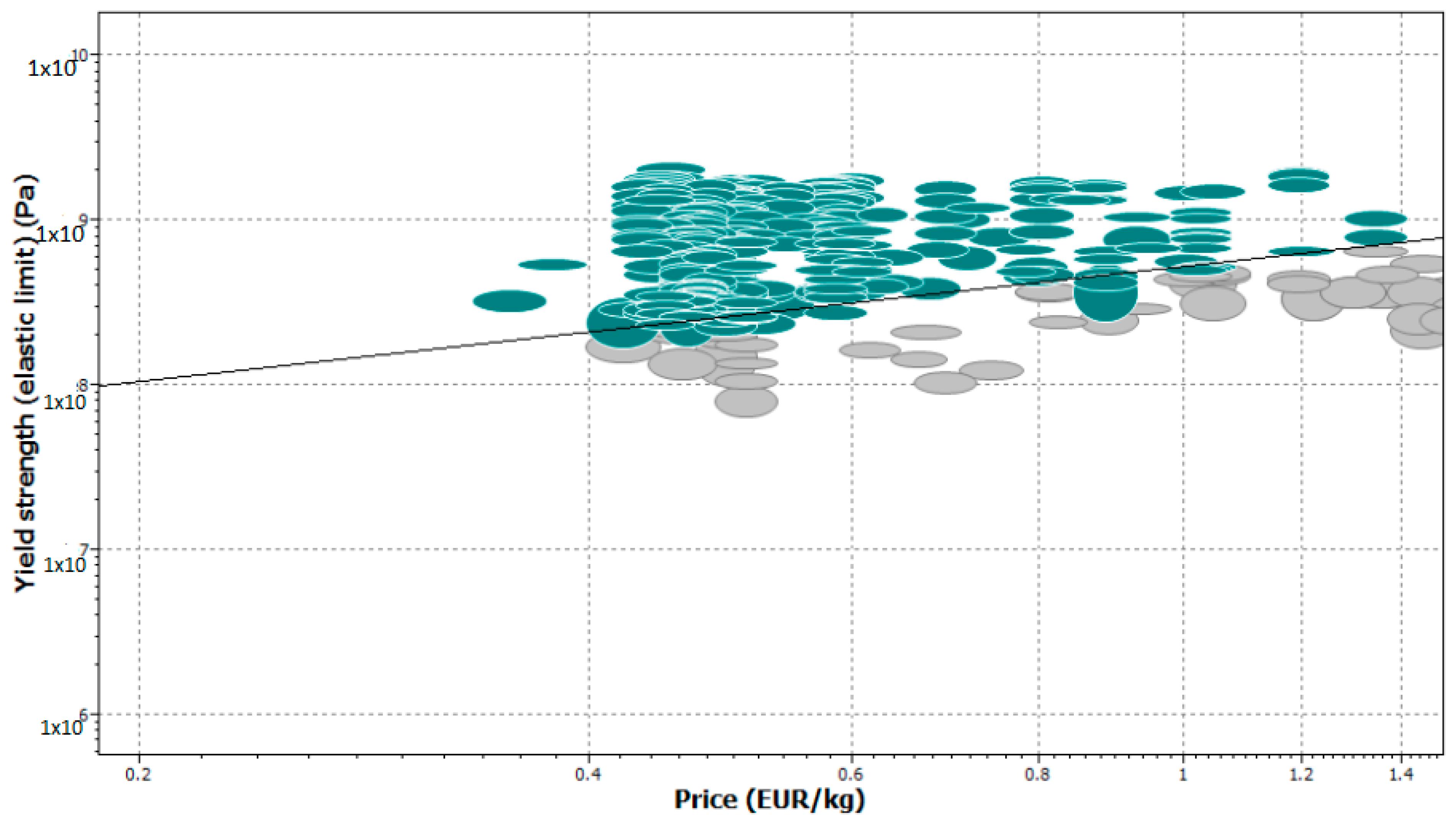
Figure 13.
Graphic selection procedure.
Figure 13.
Graphic selection procedure.
Figure 14.
Material types selected by CES Edu Pack (Ashby method).
Figure 14.
Material types selected by CES Edu Pack (Ashby method).
Figure 15.
Velocity variation under braking.
Figure 15.
Velocity variation under braking.
Figure 16.
Studied brake disc design.
Figure 16.
Studied brake disc design.
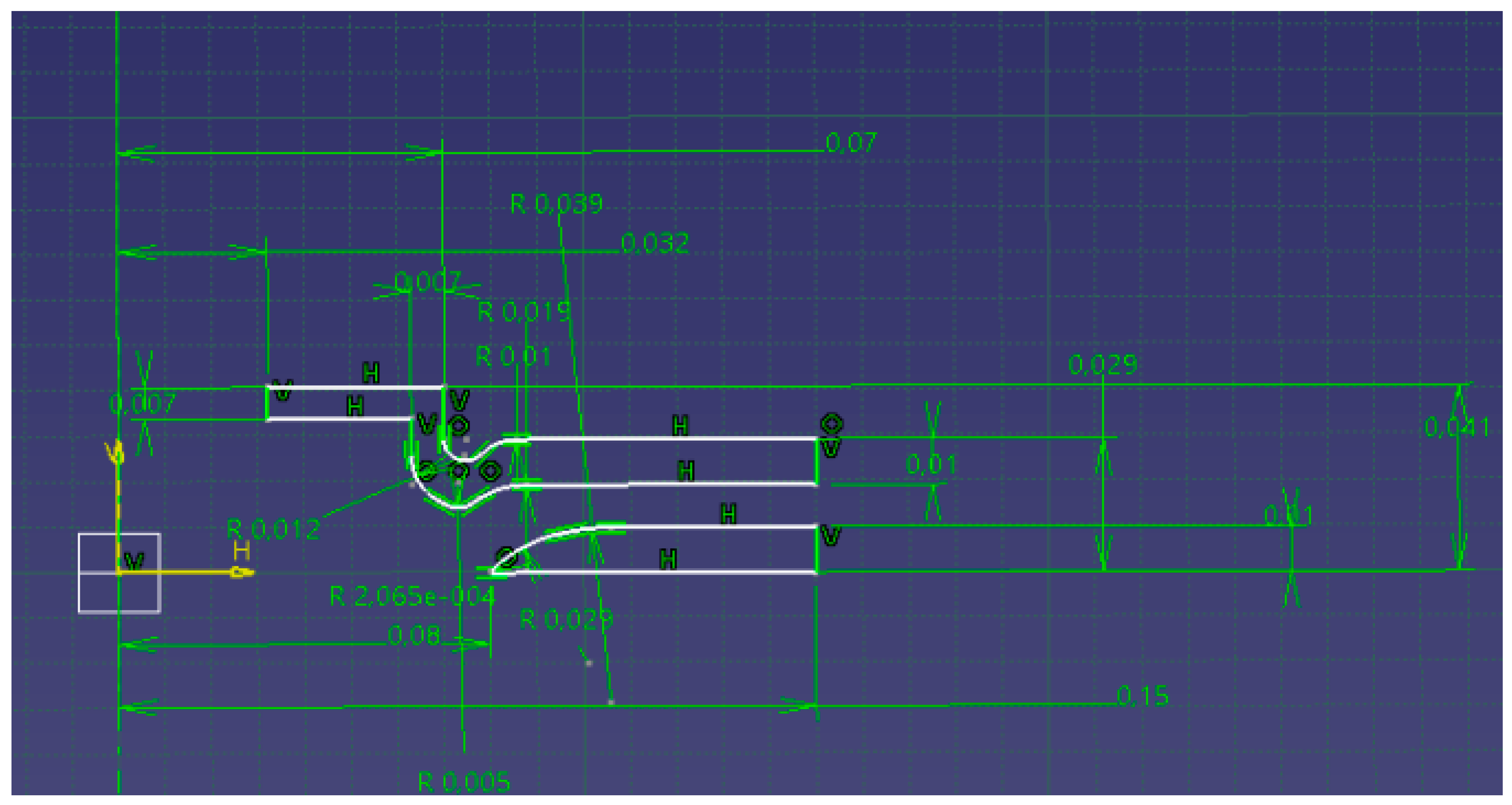
Figure 17.
Detailed sketch.
Figure 17.
Detailed sketch.
Figure 18.
Brake disc ventilation palets.
Figure 18.
Brake disc ventilation palets.
Figure 19.
Disc nodal temperature during braking.
Figure 19.
Disc nodal temperature during braking.
Figure 20.
Mechanical conditions applied in the presence of thermal data.
Figure 20.
Mechanical conditions applied in the presence of thermal data.
Figure 21.
von Mises equivalent stress in the brake disc.
Figure 21.
von Mises equivalent stress in the brake disc.
Figure 22.
Equivalent deformation in the brake disc.
Figure 22.
Equivalent deformation in the brake disc.
Figure 23.
Workflow of thermochemical coupling using Ansys.
Figure 23.
Workflow of thermochemical coupling using Ansys.
Table 1.
Proposed numerical validation plan.
Table 1.
Proposed numerical validation plan.
| Thermal Calculation | Structural Static Calculation |
|---|
- Transient calculation with Tetra mesh on Ansys with max size = 8 mm period = 45 s
- Heat flow equal to the kinetic energy dissipated by the disc at each instant (over the entire track)
- t = 0 initial
- Temperature field = 60 °C, STEP = 5 s
- Convection transfer to the air
Expected output: (the temperature field and the temperature flow) | - Cylindrical support (free tangential) on contact (hub-disc)
- Six fixed supports on mounting holes
- Pressure = 1 MPa on the contact track with each pad
- Angular speed: this is the speed of the car based on the radius of the wheel
Expected output: Equivalent stress and equivalent elastic and plastic deformation (von Mises) |
Table 2.
Material selection criteria.
Table 2.
Material selection criteria.
| Yield strength [MPa] | Re > 150 |
| Heat conduction [W/m·°C] | 50 < K < 60 |
| Mass density [kg/m3] | 7000 < ρ < 7900 |
| Specific heat [J/kg·°C] | 7800 < c < 7900 |
| Price [Euros] | Price < 2 kg/Euro |
Table 3.
Table of selected materials.
Table 3.
Table of selected materials.
| Material Name | Price (Euro/kg) | Density (104 kg/m3) |
| EN GJL 250 | 0.486–0.533 | 7.15–7.25 |
| EN GJS 350 | 0.486–0.533 | 7.07–7.15 |
| EN GJS 900 | 0.486–0.533 | 7.1–7.2 |
| EN GJN HV600 | 1.23–1.36 | 7.6–8 |
| EN GJMB 500 | 0.47–0.517 | 7.22–7.32 |
Table 4.
Order of priority for materials (cast iron).
Table 4.
Order of priority for materials (cast iron).
| Material Name | Classification | Price per Volume (Euro/m3) |
| EN GJMB 500 | 1 | 3.78 |
| EN GJS 350 | 2 | 3.81 |
| EN GJS 900 | 3 | 3.83 |
| EN GJL 250 | 4 | 3.86 |
| EN GJN HV600 | 5 | 10.88 |
Table 5.
Simulation thermal conditions.
Table 5.
Simulation thermal conditions.
| Initial conditions | 60 °C |
| Boundary conditions | - Heat flow applied to tracks = 177.489 (50–1.11 × t)
- Convective heat exchange with: coefficient of the average fluid cell temperature/stagnant air, horizontal |
| Disclaimer/Publisher’s Note: The statements, opinions and data contained in all publications are solely those of the individual author(s) and contributor(s) and not of MDPI and/or the editor(s). MDPI and/or the editor(s) disclaim responsibility for any injury to people or property resulting from any ideas, methods, instructions or products referred to in the content. |
© 2025 by the authors. Licensee MDPI, Basel, Switzerland. This article is an open access article distributed under the terms and conditions of the Creative Commons Attribution (CC BY) license (https://creativecommons.org/licenses/by/4.0/).


 ,
, 


