Article

Four-Module Cascaded Downsampling Filter for Phasemeter in Space Gravitational Wave Detection

1
Changchun Institute of Optics, Fine Mechanics and Physics, Chinese Academy of Sciences, Changchun 130033, China
2
University of Chinese Academy of Sciences, Beijing 100049, China
3
School of Electronic Information Engineering, Changchun University of Science and Technology, Changchun 130022, China
4
School of Physics and Photoelectric Engineering, Hangzhou Institute for Advanced Study, UCAS, Hangzhou 310024, China
*
Author to whom correspondence should be addressed.
Symmetry 2025, 17(2), 258; https://doi.org/10.3390/sym17020258
Submission received: 26 December 2024 / Revised: 4 February 2025 / Accepted: 6 February 2025 / Published: 8 February 2025

Abstract

:
In space gravitational wave detection, the phase information of interfering signals is read out by a phasemeter, typically output sampling at a MHz frequency. To transmit the phase information between space and ground, it must be downsampled; however, spectral aliasing during downsampling will affect the performance of the phasemeter.This paper presents a four-module cascaded downsampling filter (FCDF) with detailed module parameter design. On-board experiments conducted in a phasemeter environment demonstrate that the FCDF achieves a passband attenuation of less than 8.68 × 10 6 dB and a stopband attenuation exceeding 160 dB, enabling downsampling from 80 MHz to 3.4 Hz. Additionally, the FCDF offers improved low-frequency noise suppression, which can enhance phasemeter performance.

1. Introduction

Gravitational wave detection in space is one of the top scientific studies in modern physics and astronomy, offering new insights into the universe. Current domestic and international missions include the European and American Laser Interferometer Space Antenna (LISA) [1], China’s Taiji [2,3], and Tianqin [4,5]. The core principle involves using a laser interferometer to translate displacement changes between test masses into phase variations in the interference signal [6], which are measured by a phasemeter. The phasemeter must achieve a phase measurement sensitivity of 2 π   μ rad / Hz in the frequency band of 0.1 mHz to 1 Hz [7] for successful space gravitational wave detection.
The frequency range of the interference signal in space gravitational wave detection spans from 2 MHz to 25 MHz due to Doppler shifts [8], while the commonly used clock frequency for the phasemeter is 80 MHz [9], with output phase information sampling frequency in the MHz order. However, low-frequency gravitational wave signals must be continuously observed over long periods, which requires downsampling of phase information to meet data transmission constraints, such as the final frequency of 3.4 Hz to store and a higher sampling frequency of 102 Hz~10 Hz for the drag-free and attitude control system in LISA [10].
High-frequency noise aliasing during downsampling can affect the phasemeter’s performance in the 0.1 mHz to 1 Hz frequency band. To mitigate this, phase information must be anti-aliased during downsampling. This paper introduces a four-module cascaded downsampling filter (FCDF) to meet the downsampling requirements for phase information. Experimental results have shown that it can improve the performance of phasemeter. This paper is organized as follows: The principles of phase measurement and spectral aliasing noise are explained in Section 2; the FCDF is presented and designed with parameters in Section 3; on-board experimental tests are conducted in an electronic environment in Section 4; and the experimental results are summarized and discussed in Section 5.

2. Downsampling of the Phase Information

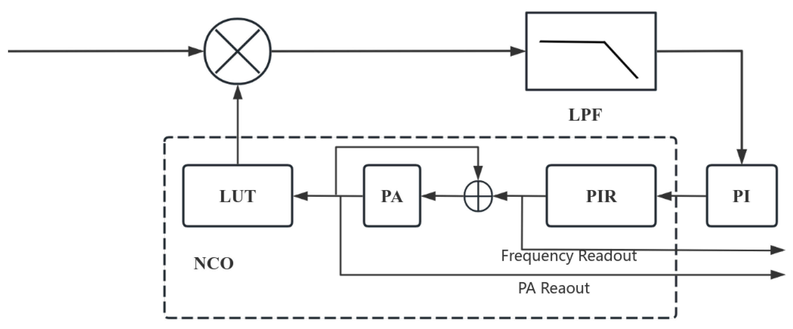
2.1. Digital Phase-Locked Loop-Based Phase Measurement

In order to track the interference signal with dynamic characteristics, the phasemeter system utilizes the Digital Phase Lock Loop (DPLL) method [11]. This makes the output signal of the local oscillator consistent with the frequency of the measured signal through feedback control, enabling the extraction of phase information from the measured signal [12,13]. The principle is illustrated in Figure 1.
The DPLL comprises a digital mixer (multiplier), a low-pass filter (LPF), a proportional-integral (PI) controller, a phase increment register (PIR), a phase accumulator (PA), and a sine look-up table (LUT). The section consisting of the LUT, the PA, and the PIR is referred to as the numerically controlled oscillator (NCO) [14]. When the measured signal enters the DPLL, it is mixed with the signal output from the NCO and low-pass filtered to produce a phase error signal. The PI controller uses this error signal to adjust the output frequency of the NCO, aligning it in both frequency and phase with the measured signal, ultimately achieving loop locking.
The DPLL features two readout methods: frequency readout (frequency value u f ) and PA readout (phase value u p ), which represent the measured signal’s frequency and phase information, respectively. Both methods can reconstruct the desired phase variations; however, u p is integrating by u f , so the phase value u p tends to rise indefinitely. Therefore, a direct readout of u p is not practical, since this value will overflow very quickly. In contrast, the u f value varies within a defined range, and integrating the frequency variations represents the phase variations. The conversion equation is as follows:
ϕ n = 2 π 1 f s i = 1 n f i f 0
where f i represents a set of frequency values [ f 1 , f 2 f n ], f s is the sampling frequency, and f 0 is the initial frequency of the measured signal. Consequently, the frequency readout in a single loop is the preferred method, with frequency variations serving as the phase information to be downsampled in this study.

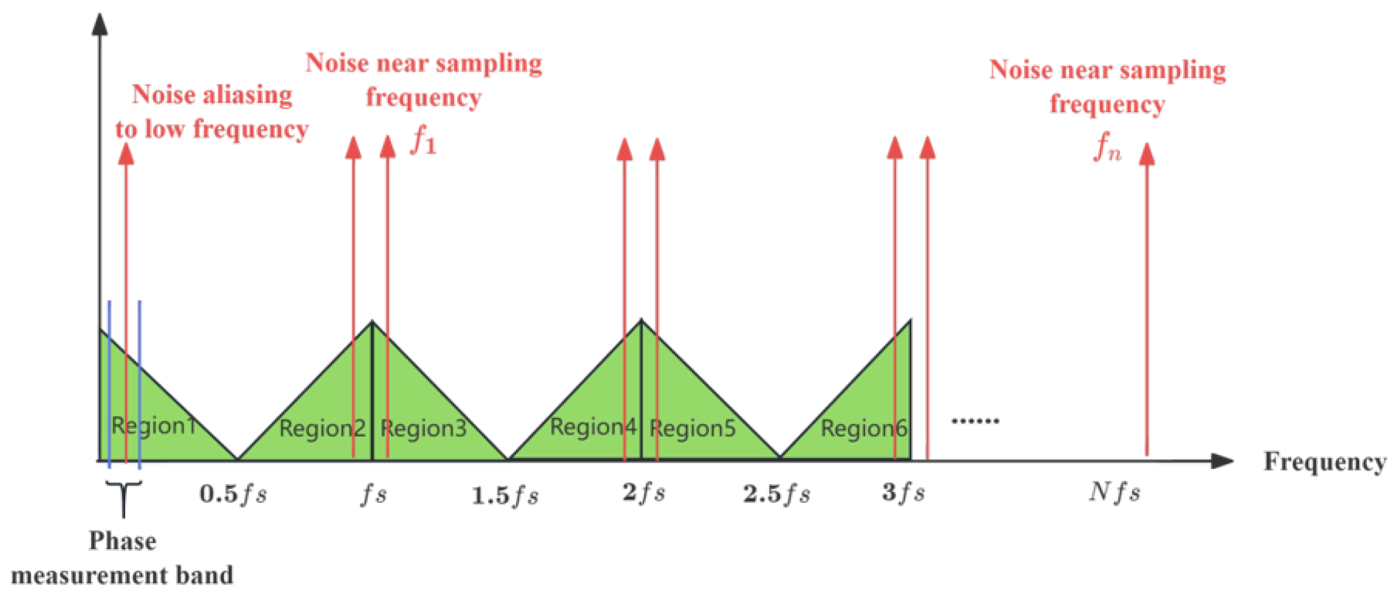
2.2. Spectral Aliasing Impact Analysis

The DPLL outputs phase information at a sampling frequency of up to 80 MHz of the system clock frequency, but the evaluation band for phasemeter sensitivity is only 0.1 mHz~1 Hz, rendering most of the bandwidth signal ineffective. According to signal and system theory, downsampling causes the high-frequency noise to alias into the low-frequency band, as illustrated in Figure 2: when the sampling frequency of the decimated signal is f s , the frequency domain will exhibit multiples of f s to unfold the aliasing region shown as the green triangle in the figure. Any original signal exceeding the Nyquist frequency will ultimately fold into region-1, represented by the following spectral aliasing equation [9]:
S k f = S n k f s + f , n k = k 2 w h e n k i s e v e n S n k f s f , n k = k + 1 2 w h e n k i s o d d
In Equation (2), S ( k ) ( f ) represents the amplitude of the k-th alias at frequency f and 0 < f < f s /2. Since the sensitive frequency band for the phasemeter is only 0.1 mHz~1 Hz, it is crucial to avoid aliasing within this range. The aliasing region map shows that only noise sources near the sampling frequency f s and its multiples f 1 f n will alias into the sensitive frequency band [15]. Therefore, to prevent spectral aliasing, it is essential to filter out noise before downsampling to eliminate any potential aliasing within the frequency band.

3. Downsampling Filter Design

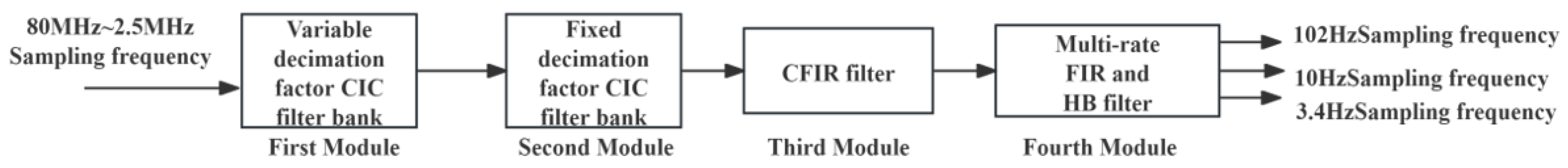
3.1. Structural Design of Downsampling Filter

Downsampling of phase information requires filtering and decimation, which can be accomplished through digital decimation filters classified as Finite Impulse Response (FIR) and Infinite Impulse Response (IIR) filters. The downsampling filter must be phase stable and linear in the passband; otherwise, it will distort the phase information [16], making FIR filters the preferred choice.
Various FIR filters can be used for downsampling, including multirate FIR filters, Cascade Integrator Comb (CIC) filters, and Half Band (HB) filters. The CIC filter, in particular, has a simple structure, excellent stability, and linear phase characteristics, making it ideal for significant decimation at high sampling frequencies [17,18]. Additionally, as analyzed in Section 2.2, only noise near the sampling frequency and its multiples will alias into the sensitive frequency band. The CIC filter’s amplitude–frequency response generates trap waves at the frequency, as shown in Figure 3, which has a large amplitude attenuating at the trap waves; thus, it can effectively suppress noise aliasing into the sensitive band.
However, the amplitude attenuation of the CIC filter in the main flap increases with frequency, negatively impacting the accuracy of phase measurements in the sensitive band [19]. To mitigate this attenuation, it is necessary to cascade an amplitude-raising compensated FIR (CFIR) filter [20,21]. The CFIR filter compensates by exhibiting an upward rise in its spectral characteristic curve within the passband range shown in Figure 4, allowing the passband attenuation of the CIC filter to be offset by appropriately setting its parameters.
In addition, the phasemeter requires outputs with low and medium sampling frequencies, specifically 102 Hz, 10 Hz, and 3.4 Hz. Due to the low sampling frequencies, the CIC filter is unsuitable; instead, the multirate FIR filter and HB filter are applicable. The HB filter features a smooth passband, zero even-order coefficients, and symmetry of the passband cut-off frequency and stopband cut-off frequency of about one-quarter of sampling frequency, making it ideal for 2-fold downsampling [22]. When combined with a multirate FIR filter, it can realize the output of the multilevel sampling frequency.
Therefore, downsampling of phase information is achieved by cascading multiple filters; specifically, a four-module cascade downsampling filter (FCDF) including a CIC filter, compensation filter, multirate FIR filter, and HB filter, as shown in Figure 5.
The first module features a variable decimation factor filter bank, including 8×, 4×, and 2× decimation CIC filters that allow for multipliers of 1~32 by cascading different decimation factors. The second module includes a fixed decimation factor CIC filter bank with three cascaded 16× CIC filters, enabling 16 3 times downsampling. The third module consists of a CFIR filter to reduce passband attenuation. The fourth module includes multirate FIR and HB filters for 2×, 3×, and 5× downsampling. This FCDF can effectively reduce high-frequency sampling frequency from 80 MHz~2.5 MHz, ultimately downsampling to 102 Hz, 10 Hz, and 3.4 Hz.

3.2. Parameter Design of Downsampling Filter

To achieve sampling frequency reduction and prevent high-frequency noise aliasing, it is essential to utilize a downsampling filter with a stopband suppression level of at least 10 8 times [16], corresponding to stopband attenuation of at least 160 dB. Additionally, to ensure accuracy of the phase measurement, the relative error in the passband must be less than 10 6 [19], which corresponds to a maximum passband attenuation of 8.68 × 10 6 dB. The FCDF parameters at all modules should be designed according to these two criteria.

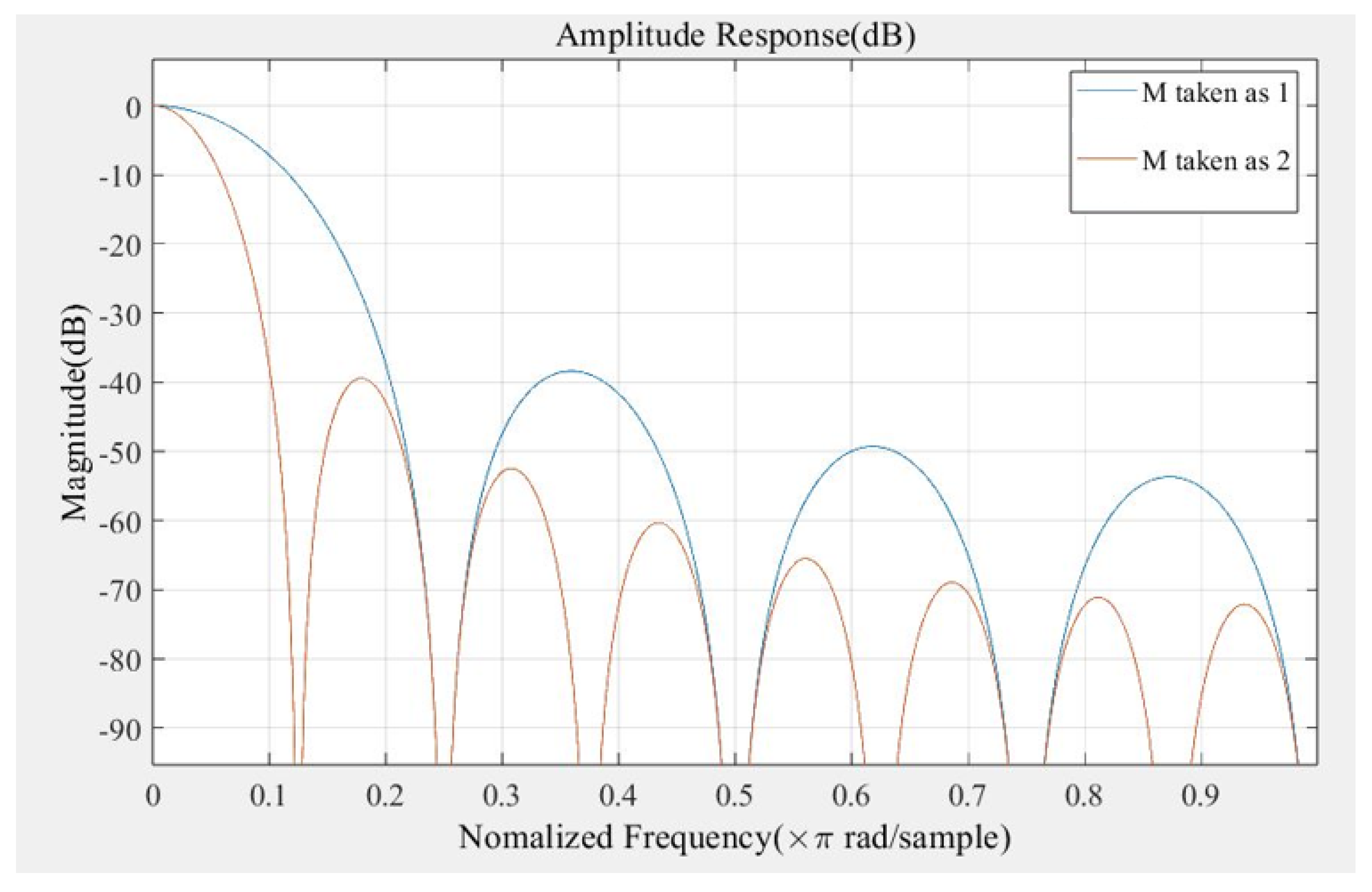
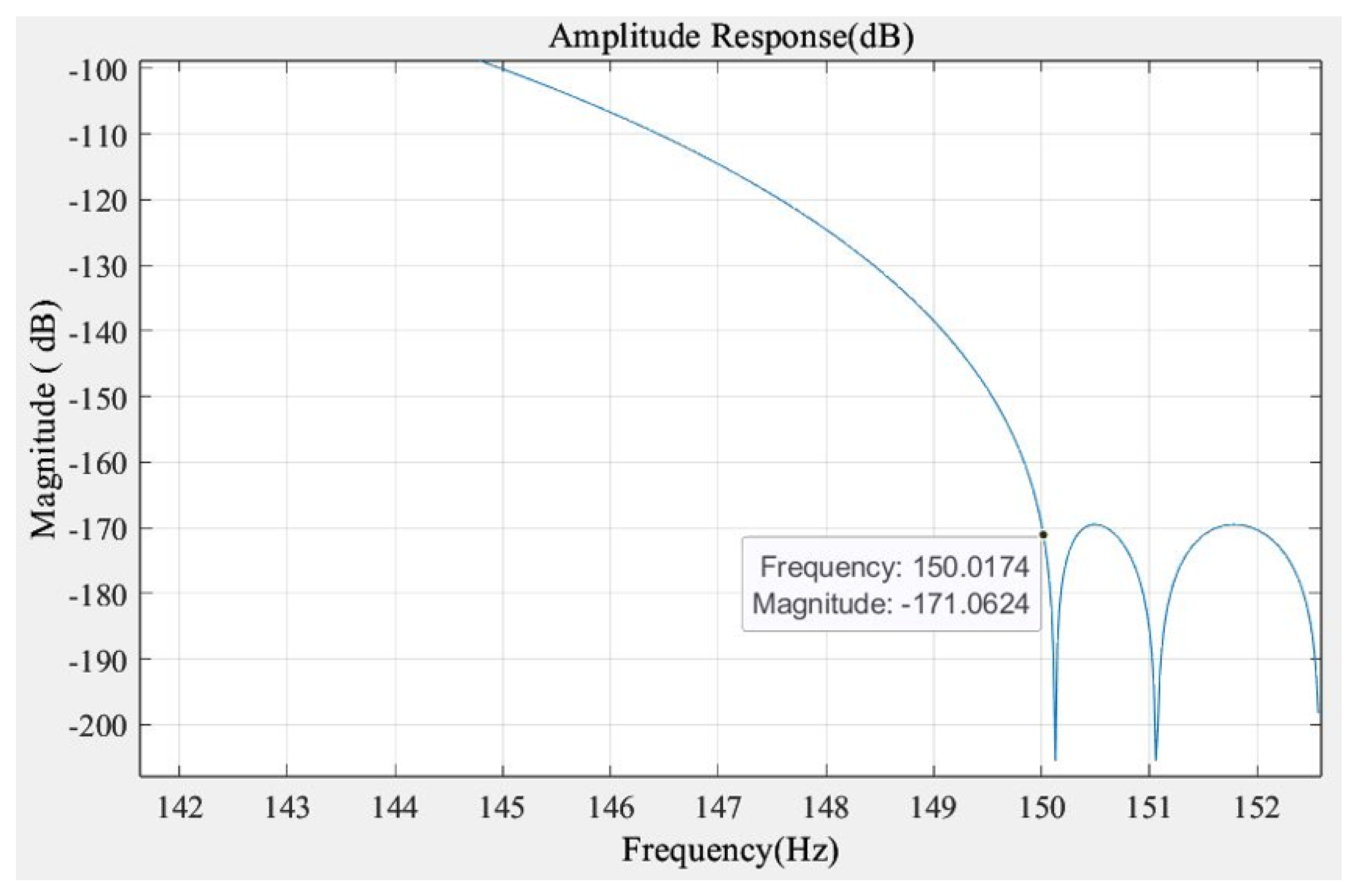
3.2.1. CIC Filter Bank Parameter Design

The first two modules of the FCDF are composed of CIC filters, so the CIC filters are parameterized uniformly. The transfer functions of the CIC filter are as follows:
H z = 1 M 1 z M D 1 z 1 N
From Equation (3), three parameters can be determined: the decimation multiplier D, differential delay M, and order N. The decimation multiplier is already established, so the other two parameters will be designed. In engineering, the differential delay M is typically set to 1 or 2, indicating an output data delay of one or two clock cycles. Figure 6 illustrates the amplitude response of the CIC filter for different values of M. A differential delay of 2 results in a flatter frequency response with a narrower transition bandwidth, providing better filtering, although it also increases amplitude attenuation within the main passband. Given that the first module operates at a sampling frequency in the MHz range, the delay effect is minimal, allowing us to set M to 2. Conversely, for the second module, which operates at a lower clock frequency, in order to reduce the time delay of the output, the differential delay M is taken as 1.
The value of order N is determined next. The order significantly influences the overall amplitude attenuation of the CIC filter; a higher order leads to greater stopband attenuation but also consumes more system resources. To achieve 160 dB amplitude attenuation with minimal resource usage, order N is set to 3. Its amplitude response is shown in Figure 7.
The final design parameters of the CIC filter in the first two modules of FCDF are obtained in the following Table 1:

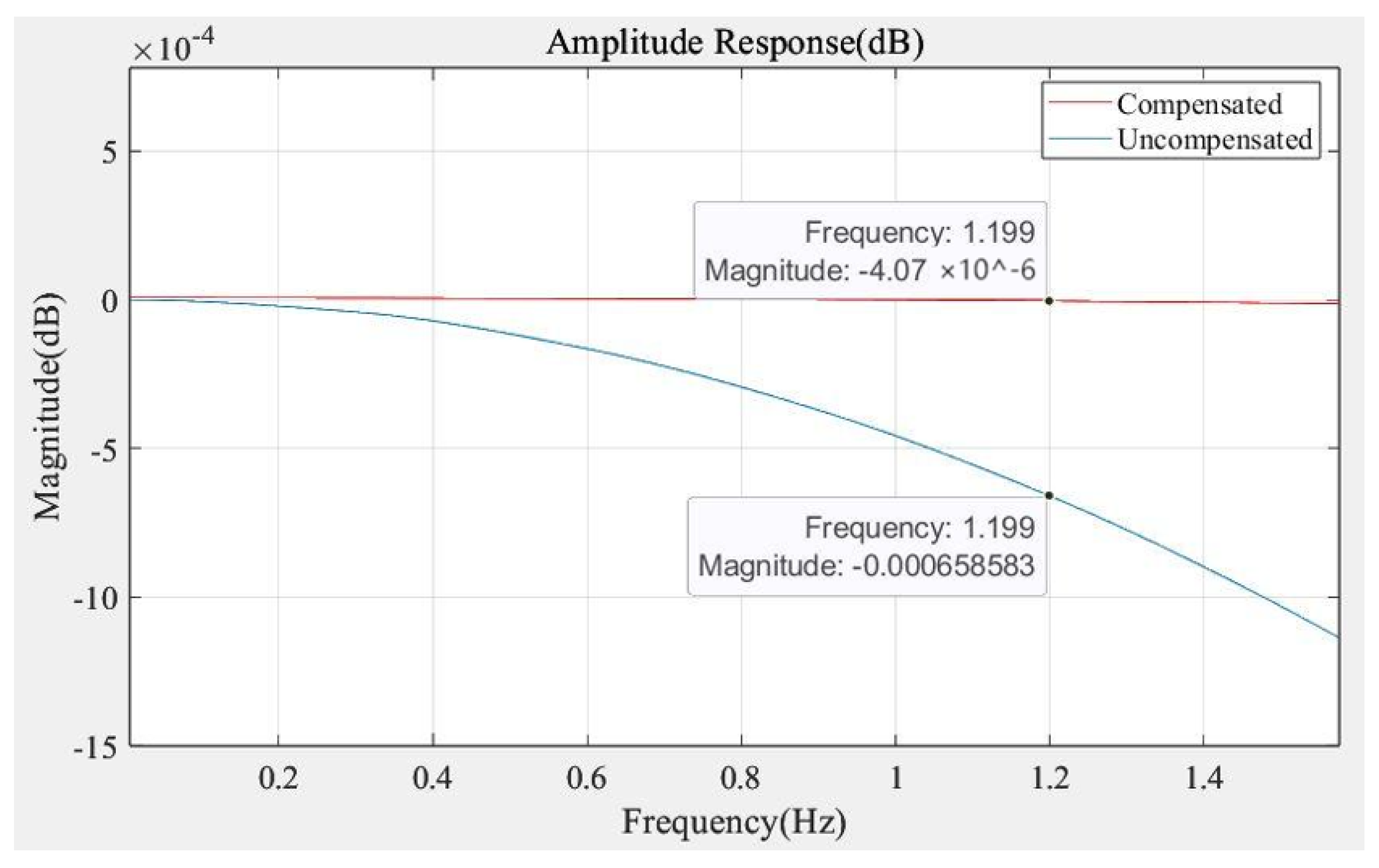
3.2.2. Compensation Filter Parameter Design

The passband attenuation near the input in the first two modules of the FCDF is negligible. However, as the sampling frequency decreases, the passband attenuation of the last CIC filter in the sensitive frequency band fails to meet the requirement of 8.68 × 10 6 dB, so it is necessary to compensate the attenuation.
The compensation filter acts as a low-pass FIR filter, with parameters including passband cutoff frequency f p a s s , stopband cutoff frequency f s t o p , passband maximum attenuation A p , and stopband minimum attenuation A s [19]. Given the sensitive frequency band of 0.1 mHz to 1 Hz, the passband cutoff frequency f p a s s should be slightly above 1 Hz but below 1.7 Hz (half of 3.4 Hz), so it is set to 1.2 Hz. The maximum f s t o p is limited to half of the sampling frequency for this module, which is 305.17 Hz. To minimize resource consumption, the transition bandwidth will be maximized, allowing the setting of f s t o p at 150 Hz. The amplitude response of the completed design of the compensation filter is shown in Figure 8.
From Figure 8, it can be seen that the maximum passband attenuation is reduced from 6.5 × 10 4 dB to 4.07 × 10 6 dB after compensating, which meets the requirement of less than 8.68 × 10 6 dB. The rejection band attenuation reaches 170 dB, meeting the requirement of more than 160 dB, as shown in Figure 9. The specific parameter design of CFIR filter is finally obtained as shown in Table 2.

3.2.3. Multi-Rate FIR, HB Filter Bank Parameter Design

The fourth module of the FCDF consists of four filters, as shown in Figure 10. Each filter has a maximum passband attenuation of less than 8.68 × 10 6 dB and a minimum stopband attenuation of over 160 dB, tailored to specific design parameters. Each filter’s passband cutoff frequency f p a s s aligns with the overall 1.2 Hz, while the stopband cutoff frequency f s t o p must be below the output sampling frequency of 1 Hz (size of the sensitive frequency band of the phasemeter). Consequently, the three FIR filters have stopband cutoff frequencies of 100 Hz, 19 Hz, and 2.4 Hz. Additionally, for the HB filter, determining the passband cutoff frequency allows for the calculation of the stopband cutoff frequency.
According to the multistage filter design requirements, each filter in this module must have a passband attenuation equal to 1/4 of the overall passband attenuation and a stopband attenuation equal to the overall stopband attenuation, which is as follows:
A p i = A p 4 i = 1 , 2 , 3 , 4
A s i = A s 4 i = 1 , 2 , 3 , 4
i in the above equation denotes the ith digital filter from left to right in Figure 10, respectively, which ultimately results in the following Table 3 of specific parameter design for the fourth filter module:
In summary, the design of the FCDF parameters is complete, and the next step is to locally implement and embed it into the phasemeter and conduct experimental tests in an electronics laboratory environment.

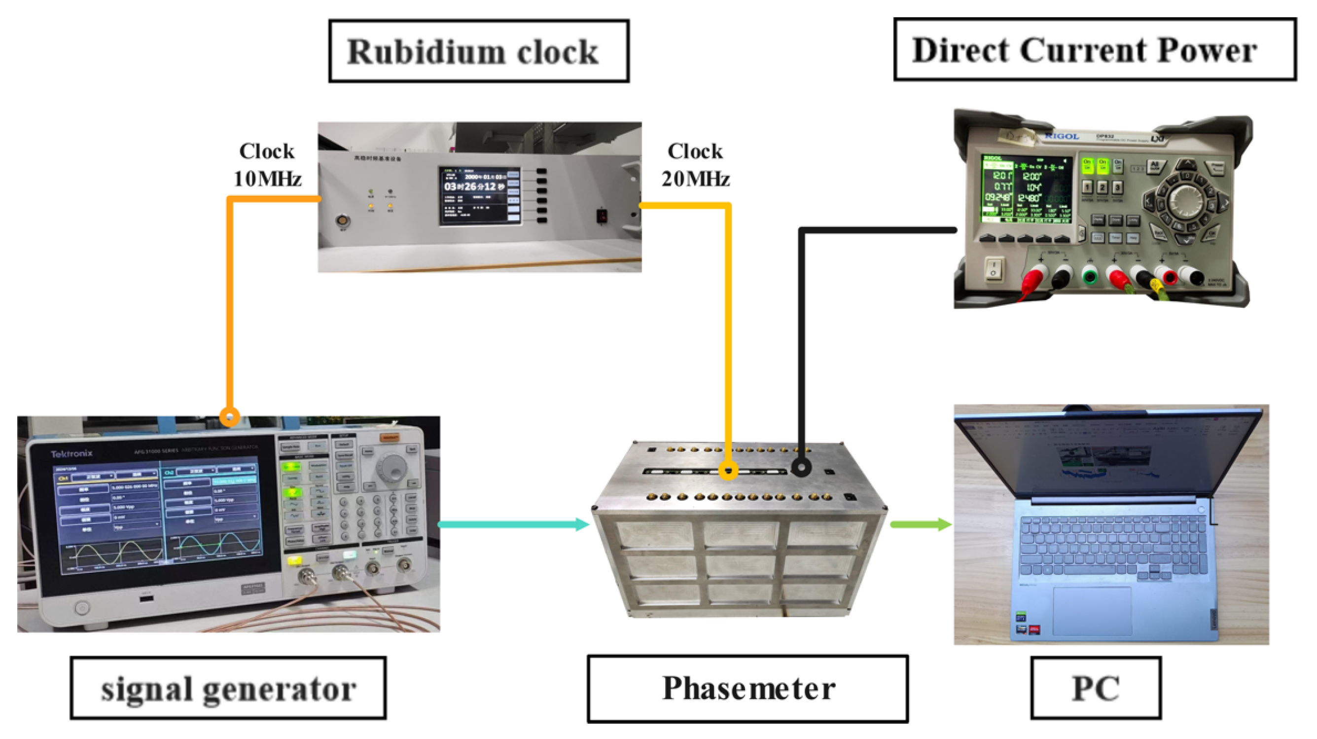
4. Experimental Testing of Downsampling Filter

The downsampling of phase information occurs in the back-end of the digital phase-locked loop, where spectral aliasing initially impacts the noise level of phase measurements within a single loop. To assess the noise rejection performance of the FCDF, experimental tests were conducted under full-link phasemeter conditions. Therefore, it is necessary to embed the downsampling filter module into the phasemeter, as shown in Figure 11.
The FCDF model designed in the previous section is implemented as a VHDL program and integrated into the phasemeter system. It is compared with the conventional CIC anti-aliasing filter bank composed solely of CIC filters to evaluate performance improvements. The hardware setup includes a K7 series FPGA, a signal generator, a rubidium clock, a DC power supply, and a PC, as shown in Figure 12. The software for the phasemeter system operates with an 80 MHz drive clock, while the signal generator produces the measurement signal. The measurement signal is the laser interference signal that simulates the actual situation and inputs it into the phasemeter. Within the phasemeter, the measured signal is locked by the phase-locked loop to produce frequency variation data with a sampling frequency of 80 MHz, which serves as the input for the decimation filter module. After being downsampled to a sufficiently low frequency, it is then transmitted to the PC via the communication module for data analysis shown in Figure 11.
We set the measured signal to a 5 MHz sinusoidal frequency with an output sampling frequency of approximately 20.34 Hz for amplitude spectral density analysis. Smoothing was applied using the LTPDA (LISA Technology Package Data Analysis) Toolbox developed by the German Albert Einstein Institute. The results are shown in Figure 13.
The curves in Figure 13 illustrate the phasemeter’s noise levels of the two channels and the results of two-channel phase common-mode reject after processing through two downsampling filters. The single-channel noise levels for both filters are quite similar, which is represented in the figure as the four blue, green, red, and yellow curves nearly overlapping, suggesting that the performance advantage of the FCDF in this study may be masked by loop noise. However, after phase common-mode rejecting, the noise level of the FCDF is significantly lower than that of the conventional CIC filter bank in the frequency range of 0.1 mHz to 0.1 Hz, as the black dashed line is lower than the pink dotted line in the figure. This indicates that the the FCDF offers improved anti-aliasing effects, enhancing the measurement sensitivity of the phasemeter system.

5. Conclusions

This paper investigates a low-noise downsampling method for phase information in a phasemeter set against the background of gravitational wave detection in space. The method employs a four-module cascade of different downsampling filters. Initially, we analyzed how data downsampling affects phase measurement sensitivity and establishes performance indices for the downsampling system, guiding the overall structure of the FCDF. It incorporates a multistage filter module structure, including CIC filters, a compensation filter, an HB filter, and multirate FIR filters, with specific designs for each module’s parameters. The FCDF effectively downsamples phase information from an 80 MHz sampling frequency to 102 Hz, 10 Hz, and 3.4 Hz, achieving a passband attenuation of less than 8.68 × 10 6 dB and a stopband attenuation exceeding 160 dB.
Compared to conventional CIC anti-aliasing filter groups, the FCDF can achieve a larger downsampling range, making it adaptable to a wider variety of scenarios. Additionally, an experimental test of the electronics in the phasemeter link compares the noise levels of the current anti-alisasing filter bank with the FCDF. The results demonstrate that the FCDF exhibits superior aliasing noise suppression in the low-frequency range, thereby enhancing the performance of the phasemeter. However, the introduction of the FIR filter significantly increased the resource usage of the FCDF, necessitating optimization to meet the requirements of the phasemeter system in future research. Finally, the research in this paper has reference significance for future space gravitational wave detection missions.

Author Contributions

Conceptualization, P.Y. and T.Y.; methodology, P.Y. and T.Y.; software, P.Y., K.X. and H.L.; validation, P.Y. and T.Y.; formal analysis, P.Y., T.Y. and M.P.; investigation, P.Y., T.Y. and M.P.; resources, T.Y., M.P., Z.W. and J.Z.; data curation, P.Y.; writing—original draft preparation, P.Y.; writing—review and editing, P.Y. and T.Y.; visualization, P.Y.; supervision, T.Y., M.P., Z.W. and J.Z.; project administration, T.Y., M.P., Z.W. and J.Z.; funding acquisition, T.Y., M.P. and Z.W. All authors have read and agreed to the published version of the manuscript.

Funding

This work was supported by the National Key R&D Program of China (2020YFC2200602), the National Key R&D Program of China (2020YFC2200604), and National Key R&D Program of China (2020YFC2200600).

Data Availability Statement

The dataset is available from the authors upon request.

Conflicts of Interest

The authors declare no conflicts of interest.

Abbreviations

The following abbreviations are used in this manuscript:
LISALaser Interferometer Space Antenna
DPLLDigital Phase-Locked Loop
NCONumerically Controlled Oscillator
FIRFinite Impulse Response
IIRInfinite Impulse Response
CICCascade Intergrator Comb
HBHalf Band
VHDLVery-High-Speed Integrated Circuit Hardware Description Language
FPGAField-Programmable Gate Array
FCDFFour-module Cascaded Downsampling Filter

References

  1. Danzmann, K. LISA and its pathfinder. Nat. Phys. 2015, 11, 613–615. [Google Scholar]
  2. Hu, W.R.; Wu, Y.L. The Taiji Program in Space for gravitational wave physics and the nature of gravity. Natl. Sci. Rev. 2017, 4, 685–686. [Google Scholar] [CrossRef]
  3. Luo, Z.; Wang, Y.; Wu, Y.; Hu, W.; Jin, G. The Taiji program: A concise overview. Prog. Theor. Exp. Phys. 2020, 2021, 05A108. [Google Scholar] [CrossRef]
  4. Hu, Y.; Mei, J.; Luo, J. TianQin project and international collaboration. Chin. Sci. Bull. 2019, 64, 2475–2483. [Google Scholar] [CrossRef]
  5. Mei, J.; Bai, Y.Z.; Bao, J.; Barausse, E.; Cai, L.; Canuto, E.; Cao, B.; Chen, W.M.; Chen, Y.; Ding, Y.W.; et al. The TianQin project: Current progress on science and technology. Prog. Theor. Exp. Phys. 2021, 2021, 05A107. [Google Scholar] [CrossRef]
  6. Luo, Z.R.; Zhang, M.; Jin, G. Overall discussion on the key problems of a space-borne laser interferometer gravitational wave antenna. Chin. Sci. Bull. 2019, 64, 2468–2474. [Google Scholar] [CrossRef]
  7. Liu, H.S.; Dong, Y.H.; Li, Y.Q.; Luo, Z.R.; Jin, G. The evaluation of phasemeter prototype performance for the space gravitational waves detection. Rev. Sci. Instrum. 2014, 85, 024503. [Google Scholar] [CrossRef]
  8. Gerberding, O.; Sheard, B.; Bykov, I.; Kullmann, J.; Delgado, J.J.; Danzmann, K.; Heinzel, G. Phasemeter core for intersatellite laser heterodyne interferometry: Modelling, simulations and experiments. Class. Quantum Gravity 2013, 30, 235029. [Google Scholar] [CrossRef]
  9. Staab, M.; Lilley, M.; Bayle, J.B.; Hartwig, O. Laser noise residuals in LISA from onboard processing and time-delay interferometry. Phys. Rev. D 2024, 109, 043040. [Google Scholar] [CrossRef]
  10. Liang, Y.R. High Precision Phase Measurement for Heterodyne Laser Interferometer. Ph.D. Thesis, Huazhong University of Science and Technology, Wuhan, China, 2013. [Google Scholar]
  11. Zhang, J.; Yang, Z.; Ma, X.; Peng, X.; Liu, H.; Tang, W.; Zhao, M.; Gao, C.; Qiang, L.E.; Han, X.; et al. Inter-spacecraft offset frequency setting strategy in the Taiji program. Appl. Opt. 2022, 61, 837–843. [Google Scholar] [CrossRef]
  12. Luo, Z.R.; Yu, T.; Liu, H.S. Taiji Scientific Collaboration. The phasemeter of Taiji-1 experimental satellite. Int. J. Mod. Phys. A 2021, 36, 2140005. [Google Scholar] [CrossRef]
  13. Liu, H.; Luo, Z.; Jin, G. The Development of Phasemeter for Taiji Space Gravitational Wave Detection. Microgravity Sci. Technol. 2018, 30, 775–781. [Google Scholar] [CrossRef]
  14. Kullmann, J. Development of a Digital Phase Measuring System with Microradian Precision for LISA. Ph.D. Thesis, Leibniz University Hannover, Hannover, Germany, 2012. [Google Scholar]
  15. Liang, Y.R.; Ye, X.J. High-precision phasemeter for inter-satellite laser ranging. In Proceedings of the 8th Annual Academic Meeting of the Deep Space Exploration Technology Committee of the Chinese Society of Astronautics, Shanghai, China, 26 October 2011. [Google Scholar]
  16. Ware, B.; Folkner, W.M.; Shaddock, D.; Spero, R.; Halverson, P.; Harris, I.; Rogstad, T. Phase Measurement System for Inter-Spacecraft Laser Metrology. 2006. Available online: https://www.researchgate.net/publication/242087596_Phase_Measurement_System_for_Inter-Spacecraft_Laser_Metrology (accessed on 29 June 2006).
  17. Li, S. Research and Design of Digital Decimation Filter in Audio Sigma-Delta ADC. Master’s Thesis, Huazhong University of Science and Technology, Wuhan, China, 2022. [Google Scholar]
  18. Yu, Z. Design of A CIC digital filter in sigma-delta ADC. China Integr. Circuit 2024, 33, 34–36. [Google Scholar]
  19. Yang, R.; Liu, H.; Luo, Z. Optimization Design of Decimation Filter for the Phasemeter in the Space Gravitational Wave Detection. IEEE Trans. Instrum. Meas. 2024, 73, 7006508. [Google Scholar] [CrossRef]
  20. Tian, D.; Chen, Y.Z. Research and Performance Analysis of CIC Filter Compensation Method. In Proceedings of the 12th National Conference on Signal and Intelligent Information Processing and Application, Nanjing, China, 8–10 March 2024. [Google Scholar]
  21. Shen, Z.S.; Liu, Y.T.; Fang, S.; Wang, Y. A Digital Decimation Filter of Σ-ΔADC with Ultra-Low power and Small Area. Microelectronics 2022, 52, 555–561. [Google Scholar]
  22. Wan, R.; Li, Y.; Tian, C.; Yang, F.; Deng, W.; Tang, S.; Wang, J.; Zhang, W. Design and Implementation of Sigma-Delta ADC Filter. Electronics 2022, 11, 4229. [Google Scholar] [CrossRef]
Figure 1. Digital phase-locked loop schematic. LUT: Look-Up Table, PA: Phase Accumulator, NCO: Numerically Controlled Oscillator, PIR: Phase Increment Register, PI: Proportional Integral, LPF: Low-Pass Filter.
Symmetry 17 00258 g001
Figure 2. Spectral aliasing area map. The triangles correspond to areas of spectral aliasing, while red lines indicate noise close to the sampling frequency.
Symmetry 17 00258 g002
Figure 3. Schematic of the trap generated by the CIC filter.
Symmetry 17 00258 g003
Figure 4. CIFR filter amplitude response plot.
Symmetry 17 00258 g004
Figure 5. Four-module cascade downsampling filter.
Symmetry 17 00258 g005
Figure 6. Comparison of amplitude response of CIC filter with M taken as 1 and M taken as 2.
Symmetry 17 00258 g006
Figure 7. Comparison of amplitude attenuation at the trap when CIC filter order is taken as 2 and 3. The red line represents the 160 dB stopband attenuation index, with N set to 3 at the trap to achieve over 160 dB.
Symmetry 17 00258 g007
Figure 8. The amplitude response of the compensation filter: Passband attenuation before and after compensation.
Symmetry 17 00258 g008
Figure 9. The amplitude response of the compensation filter: Stopband attenuation of compensation.
Symmetry 17 00258 g009
Figure 10. Schematic diagram of the structure of the fourth module downsampling filter.
Symmetry 17 00258 g010
Figure 11. Schematic of embedding a downsampling filter module into a phasemeter.
Symmetry 17 00258 g011
Figure 12. Experimental test environment for electronics.
Symmetry 17 00258 g012
Figure 13. Noise test of phasemeter with two downsampling filters.
Symmetry 17 00258 g013
Table 1. Design parameters of CIC filters in the first and second module.
Variable Decimation Factor Filter BankFixed Decimation Factor Filter Bank
Decimation multiplier: 2/4/8Decimation multiplier: 16
Diffierential delay: 2Diffierential delay: 1
Order: 3Order: 3
Table 2. Design parameters in the third-stage compensation filter bank.
Passband cutoff frequency1.2 Hz
Stopband cutoff frequency150 Hz
Passband maximum attenuation 4.04 × 10 6 dB
Stopband minimum attenuation170 dB
Table 3. Design parameters of FIR and HB filters in the fourth filter module.
Multi-Rate FIR FilterHB Fliter
Passband cutoff frequency: 1.2 HzPassband cutoff frequency: 1.2 Hz
Stopband cutoff frequency: 100/19/2.4 HzStopband cutoff frequency: 8.8 Hz
Decimation factor: 3/5/3Decimation factor: 2
Passband max attenuation: 2.17 × 10 6  dBPassband max attenuation: 2.17 × 10 6  dB
Stopband minimum attenuation: 160 dBStopband minimum attenuation: 160 dB
Disclaimer/Publisher’s Note: The statements, opinions and data contained in all publications are solely those of the individual author(s) and contributor(s) and not of MDPI and/or the editor(s). MDPI and/or the editor(s) disclaim responsibility for any injury to people or property resulting from any ideas, methods, instructions or products referred to in the content.

