Article

Investigating the Symmetric Control of a Hydraulic System Based on Status Feedback

1
College of Intelligent Manufacturing, Hunan First Normal University, Changsha 410205, China
2
College of Electronic Information, Hunan First Normal University, Changsha 410205, China
3
Principal’s Office, Hunan Industry Polytechnic, Changsha 410208, China
4
College of Mechanical and Electrical Engineering, Central South University, Changsha 410083, China
*
Authors to whom correspondence should be addressed.
Symmetry 2025, 17(2), 246; https://doi.org/10.3390/sym17020246
Submission received: 21 December 2024 / Revised: 26 January 2025 / Accepted: 31 January 2025 / Published: 7 February 2025
(This article belongs to the Section Engineering and Materials)

Abstract

:
Valve-controlled hydraulic systems are widely used in various hydraulic equipment, but their asymmetric characteristics are the most critical factor restricting further improvements in system performance. This paper takes large asymmetric complex hydraulic equipment as the industrial background, and proposes a state feedback-based symmetric switching control method to address the complex control strategy and difficult control accuracy caused by input–output asymmetry and the inconsistent response of asymmetric valve-controlled hydraulic systems. A system state space model is established, and the parameterized expression that satisfies the state space switching-based symmetric control law is solved. Feedback and feedforward links based on state space symmetric switching are designed to transform the asymmetric system into a state space symmetric system. And the research results will be applied to the experimental setup of the 300 MN forging hydraulic press control system. Through simulation verification, under asymmetric PID control conditions, due to the influence of the asymmetric characteristics of the system structure, load, and their coupling relationship, the forward response time is shorter than the unloaded response time, and the overshoot is larger than the unloaded response time. The reverse response time is longer than the unloaded response time, and the overshoot is smaller than the unloaded response time. After symmetric control, the forward and reverse dynamic system characteristic curves completely overlap, proving that the system has achieved symmetric transformation; through experimental verification, under asymmetric PID control conditions, when the proportional valve opening remains constant, changes in the load pressure will cause changes in the load speed. For every 1 MPa increase in the load pressure, the load speed will slow down by about 0.0033 m/s. The load speed of the system after symmetrical control replacement will be much less affected by changes in the load pressure. The simulation and experimental results have shown that this method is expected to solve the key problem of inconsistent dynamic characteristics of complex equipment hydraulic systems in both the forward and reverse directions due to asymmetry, and the inability to ensure control accuracy in both directions using symmetric control strategies. This paper has developed a set of control theories and methods applicable to hydraulic systems with complex asymmetry.

1. Introduction

Asymmetric valve-controlled hydraulic cylinder systems are widely used in various pieces of large-scale equipment. To achieve a high response, high precision, and strong robustness of the system, enriching and developing the theory of asymmetric valve-controlled hydraulic cylinder systems, conducting research on the asymmetric characteristics and symmetric control of the system is an important measure to promote the intelligent process of manufacturing and improve productivity [1]. At present, due to the asymmetry of the structure and load of the valve-controlled hydraulic cylinder system, the dynamic and static characteristics of the hydraulic cylinder in the two directions of extension and retraction, such as the offset of the balance position, stability, and overshoot changes, are inconsistent, which brings great difficulties to the modelling and control of the valve-controlled hydraulic cylinder system and becomes the most critical factor restricting the further improvement of system performance. The existing studies lack a unified and portable control strategy [2]. Valve-controlled hydraulic systems are commonly used to control the opening and closing of various large hydraulic equipment drive mechanisms and the flow and direction of working media, thus achieving the actions of various actuators in large hydraulic equipment [3,4]. Owing to the large diameter, high flow rate, and high pressure of the driving devices of large hydraulic equipment, their opening forces are enormous. Therefore, the opening force is usually used as a key functional component for controlling hydraulic equipment, considering that the opening and closing actuator action directly affects the performance of the hydraulic equipment control [5,6].
The valve-controlled hydraulic system of large-scale hydraulic equipment integrates mechanical, electrical, and hydraulic control, with relatively high working pressures and load flow rates and large structural dimensions. The system operating conditions are complex, and the coupling relationships between various parameters are complex [7]. Owing to the asymmetric characteristics of parameters such as the structure, external load, friction, damping coefficient, and natural frequency, the actuator of a valve-controlled hydraulic system has different characteristics in the opening and closing directions [8].
This strong asymmetry and time-varying nature, if not handled well during the design process, of valve-controlled hydraulic control systems can greatly affect the quality of control. A single controller often cannot simultaneously meet the requirements of speed and stability in both the opening and closing directions [9,10]. If the system parameters are set in the slower direction, oscillations will occur in the faster direction. If the system parameters are set in the faster direction, the response speed in the slower direction will decrease [11]. In addition to the structural asymmetry of the system itself, there are significant differences in the external load force between the opening and closing directions, indicating the existence of asymmetry between the external load and the system’s structure during operation [2,12].
To reduce the impact of asymmetry in valve-controlled hydraulic systems on control accuracy, further studies have been conducted on asymmetric characteristics for controlling valve-controlled hydraulic systems in large and complex equipment [13,14]. The asymmetric model of the asymmetrical hydraulic cylinder position system controlled by a valve is established, and this model has adopted a PID control strategy to improve the system characteristics [15]. The system is sensitive to changes in load and switching frequency. A robust controller is designed [16], which requires position and velocity feedback to address the asymmetric and time-varying characteristics of the inclined plate control system of the piston pump. The controller can ensure that both the position and velocity meet the requirements simultaneously. A wave energy hydraulic conversion system is proposed to address the asymmetric characteristics of loads [17]. Using predictive multimode fuzzy control technology, the system achieved smooth position control of high-inertia moving components in both the forward and reverse directions.
Overall, not only have these studies proposed many improved PID control strategies for asymmetric valve-controlled hydraulic systems [1,18,19,20], but theoretical and experimental analysis results have also shown that these strategies can improve the control performance of onsite equipment to a certain extent [21,22,23]. However, the experimental hardware of these improved PID control strategies is not suitable for large-scale hydraulic equipment on industrial sites. The inherent asymmetry, time-varying nature, and uncertainty of hydraulic systems cannot be fully matched by PID control strategies based on symmetric control theory [24,25,26]. Therefore, it is necessary to carry out a detailed study on the relationship between the dynamic and asymmetric characteristics of valve-controlled hydraulic systems used in large hydraulic equipment [27,28].
Therefore, this work starts by solving the control problem of asymmetric valve-controlled hydraulic systems used in large hydraulic equipment and proposes a systemic symmetric control method based on state response, aiming to address the difficulty in debugging control parameters and poor control strategy portability caused by the inconsistency of forward and reverse dynamic responses and input–output inconsistency in asymmetric systems. These findings provide theoretic and practical references for improving the control properties of large hydraulic equipment.
(1) At present, the application of an asymmetric structure in valve-controlled hydraulic systems has made the control system more complex and has led to higher design costs and worse effectiveness in eliminating pressure jumps and motion asymmetry. (2) Although aiming at the asymmetric and nonlinear characteristics of hydraulic systems, improved PID control strategies such as sliding mode control, robust control, adaptive control, feedback linearization control, or their composite controls have been designed to eliminate asymmetric responses. These are essentially asymmetric controllers that require a large number of control parameters to be debugged. Not only is the onsite debugging workload large, but the design and debugging personnel also need a solid theoretical foundation, and the current method portability is poor. (3) On the other hand, the control strategy of symmetric systems is relatively simple due to their unique structure, and the control methods of symmetric systems are highly portable. Therefore, there should be good application prospects for treating asymmetric factors as system variables, decoupling complex equipment hydraulic systems through asymmetric control methods, and ultimately using symmetric system control theory to solve the control problems of asymmetric systems. In summary, the control and application problems for symmetric systems have become very mature, but there have been no examples of converting asymmetric systems into symmetric systems through state space and applying them to engineering practice. Therefore, the development and research prospects of how to use symmetric control for asymmetric systems are very broad.
In the second section of this paper, the experimental setup of the 300 MN hydraulic press control system is used to establish a simulation model of the system and determine its parameters. In the third section, the forward and backward consistency responses of the system under two different control strategies, asymmetric PID control and symmetric conversion control, are first verified. Then, two different control strategies were applied to the simulation experimental device of the 300 MN hydraulic press control system to verify the input–output symmetry differences in the system under the two different control strategies.

2. System Modelling

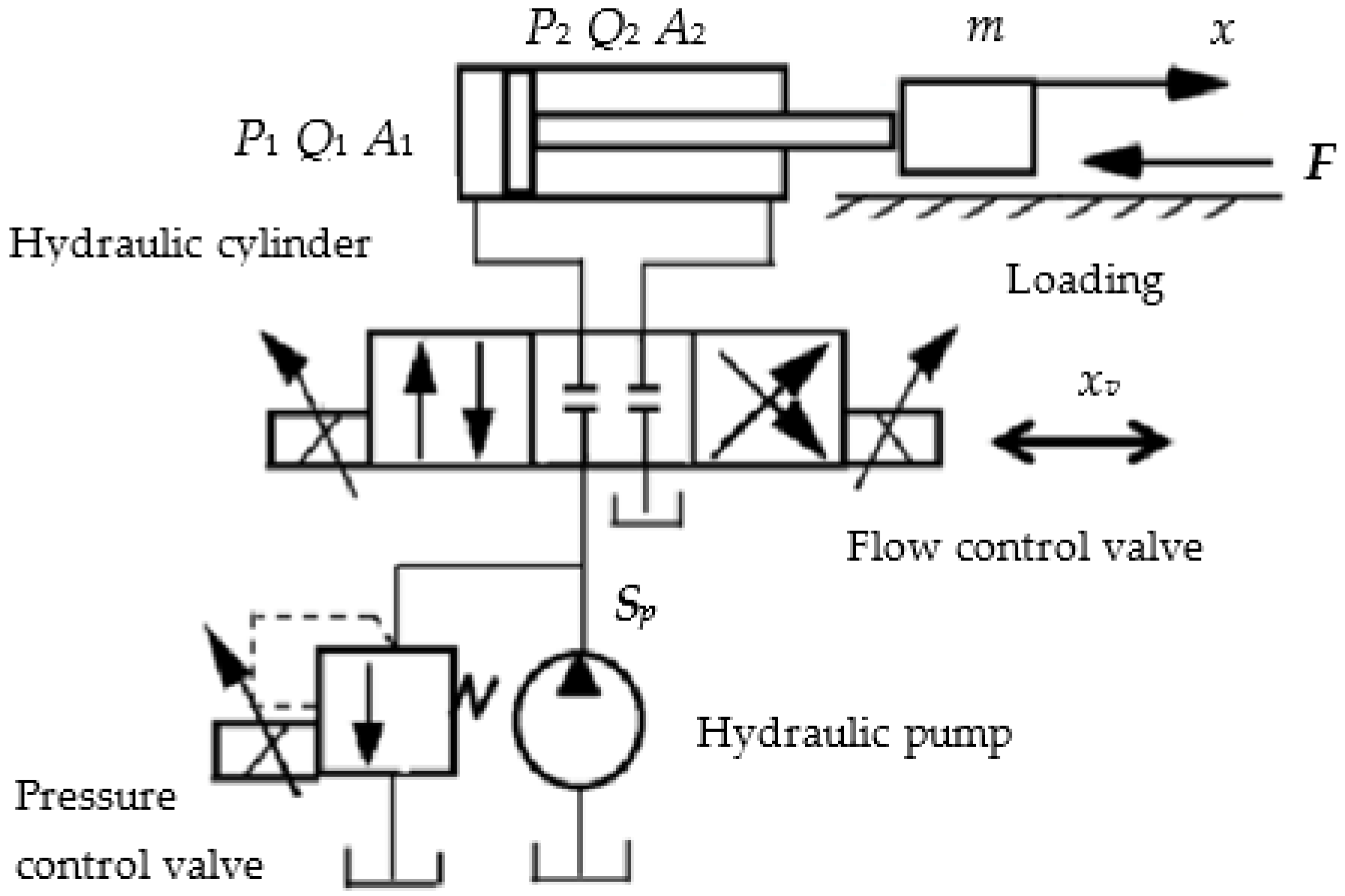
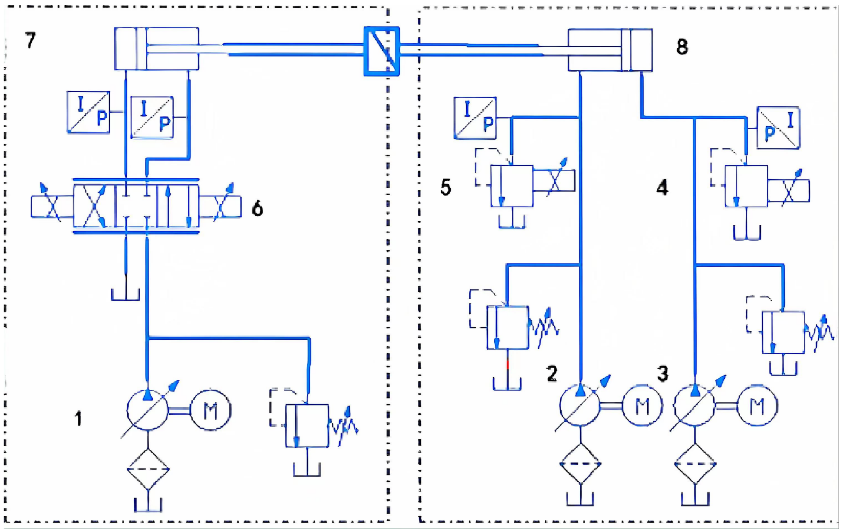
2.1. Basic Description

The working principle of the hydraulic system controlled by a valve, which is composed of a hydraulic pump, a pressure control valve, a flow control valve, a hydraulic cylinder, and an inertial load, is shown in Figure 1. xv is the control valve spool displacement, m is the inertial load mass, F is the inertial load, x is the load displacement, P1, Q1, and A1 represent the working chamber pressure, flow rate, and effective working area, respectively, and P2, Q2, and A2 represent the return oil chamber pressure, flow rate, and effective working area, respectively.

2.2. Mathematical Model of the System State Space

The modelling of the system is based mainly on the flow equation of the flow control valve, the flow continuity equation of the system working chamber and return chamber, and the force balance equation of the load:
The flow equation is
Q 1 = C d x K c 1 ( P 1 P 2 )
where K c 1 is the proportional valve port pressure coefficient, and C d is the flow coefficient of the proportional valve port.
The flow continuity equations for the working chamber and the return chamber are
Q 1 C i c ( P 1 P 0 ) C e c P 1 = A 1 d x d t + V 1 β e d P 1 d t
C i c ( P 2 P 0 ) C e c P 1 Q 2 = A 2 d x d t + V 2 β e d P 2 d t
where C i c is the system leakage coefficient, C e c is the leakage coefficient within the system, P 0 is the return oil pressure, V 1 is the initial volume of the working chamber, V 2 is the initial volume of the return chamber, β e is the effective bulk elastic modulus of hydraulic oil, and t is the simulation time.
The force balance equation for the plunger is
P 1 A 1 P 2 A 2 F F b = m d x 2 d t 2
where F b is the friction resistance during the load operation, Due to the much smaller load force here, it is ignored.
Equations (1)–(4) are combined to obtain the mathematic modelling of the hydraulic system controlled by a valve:
Q 1 = C d x v K c 1 ( P 1 P 2 ) Q 1 C i c ( P 1 P 0 ) C e c P 1 = A 1 d x d t + V 1 β e d P 1 d t C i c ( P 2 P 0 ) C e c P 1 Q 2 = A 2 d x d t + V 2 β e d P 2 d t P 1 A 1 P 2 A 2 F = m d x 2 d t 2
The flow into the working chamber is positive and the flow out of it is negative, and the flow out of the return chamber is positive and the flow into it is negative. When the working chamber advances, the direction is defined as forward, and when it retreats, it is defined as reverse. The force that hinders the advancement of the working chamber is defined as the pressure, and the force that promotes the advancement of the working chamber is defined as the tension.
Assume that x 1 = x ˙ , x 2 = p 1 , x 3 = p 2 , u 1 = x v , u 2 = F . Ignoring the frictional resistance during plunger operation (because frictional resistance can be converted into a load force during the simulation), if the area ratio of the return chamber to the working chamber is n and the cavity pressure is zero, then according to Equation (5), the mathematic modelling of the system status space can be expressed as
x ˙ 1 = A 1 m x 2 A 2 m x 3 1 m F x ˙ 2 = β e V 1 A 1 x 1 β e V 1 ( K c 1 + C i c + C e c ) x 2 + β e V 1 K c 1 x 3 + β e V 1 C d u 1 x ˙ 3 = β e V 2 A 2 x 1 + β e V 2 ( n K c 1 C e c ) x 2 β e V 2 ( C i c + n K c 1 ) x 3 β e V 2 n C d u 1 y 1 = x 1 y 2 = x 2
System (6) is an asymmetric state space system, and according to the definition of a symmetric system, for the state space system, x ˙ = A x + B u y = C x . If A = A T , C T = D are satisfied, then the system is a state space symmetric system. The target of this paper is to transform system (6) into a symmetric system by finding a feedback controller K and a feedforward controller L.

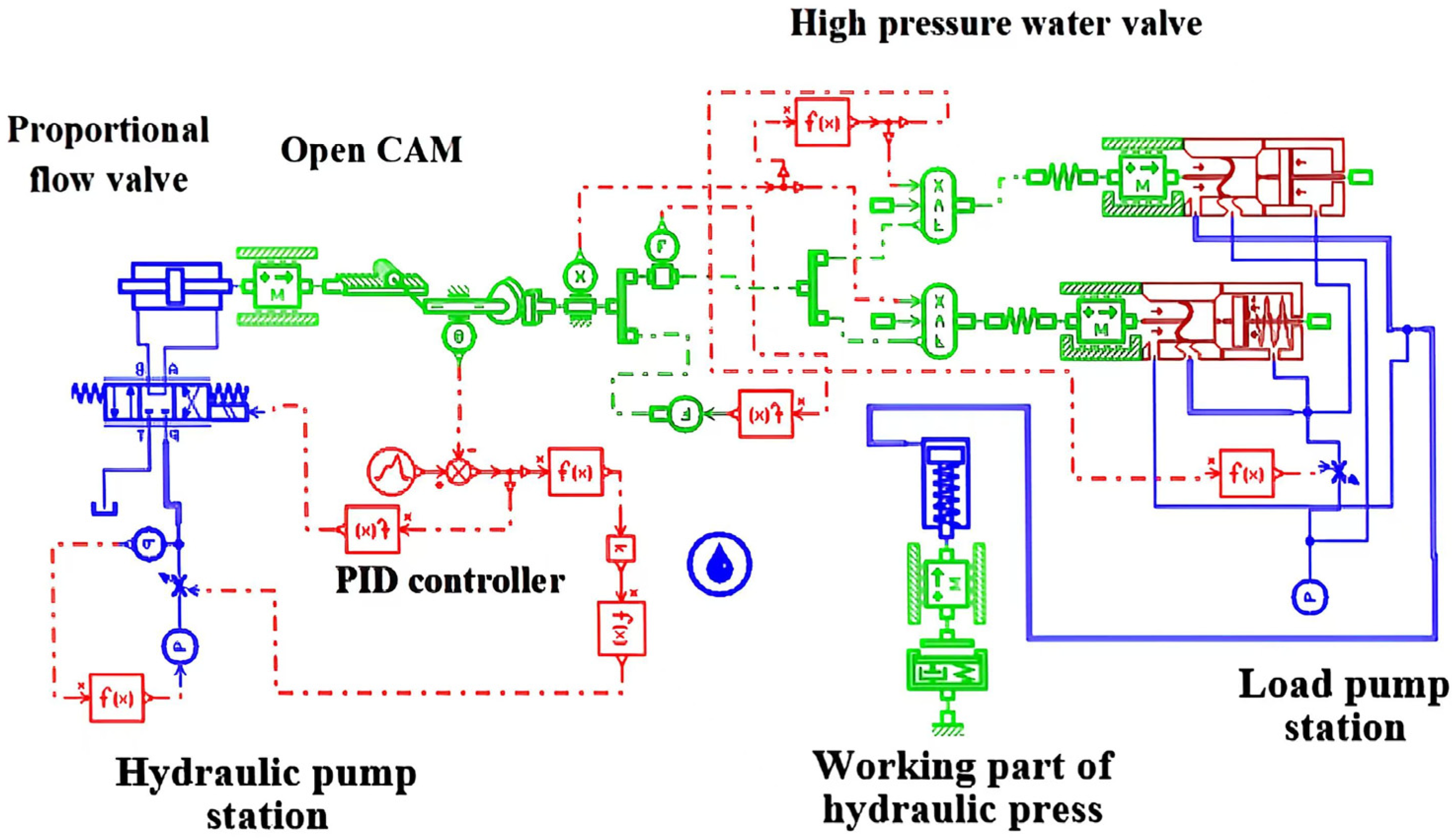
2.3. System Simulation Model

The typical application equipment of a valve-controlled hydraulic system, a 300 MN forging hydraulic press control system, is used as the carrier. The working process of the control system is as follows: the hydraulic system drives the actuator (commonly known as the relay) to move the plunger of the working cylinder in a straight line and converts the linear motion of the plunger of the working cylinder into the rotary motion of the camshaft through the gear rack mechanism. Then, the cam rod mechanism pushes the main valve core to a certain opening height, opening each distributor’s main valve core and completing various actions of the press. The movement of the rack plunger is controlled by a proportional directional valve, so the control system of a large hydraulic press is essentially a valve-controlled cylinder system. Using AMESim hydraulic modelling and simulation software, a composite model integrating fluid dynamics, machinery, and electrical control was established, as shown in Figure 2, with the modelling parameters listed in Table 1.

3. Results and Discussion

3.1. Influence of Asymmetric Dynamic Characteristics of Systems

The working pressure of the pump station is set to 6 MPa, and the system load force range is 5000   N < F L < 50,000   N . The other simulation parameters are shown in Table 1.

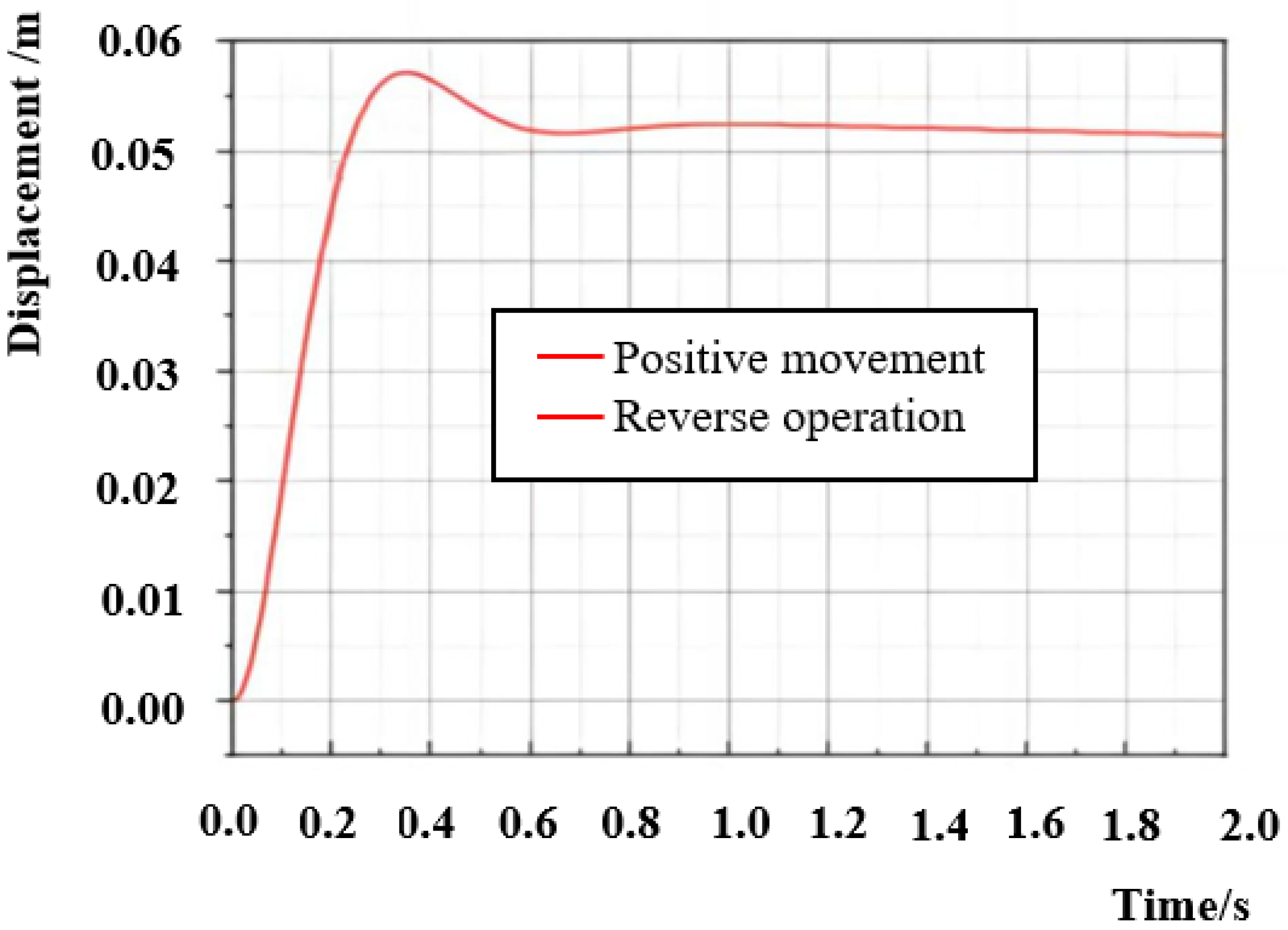
3.1.1. Influence of Asymmetric Structure on Dynamic Characteristics

Based on the structure, working principle, and system model of the large-scale hydraulic press control system (6), a composite model integrating fluid dynamics, mechanical, and electrical control was established using AmeSim2020.1 hydraulic modelling and simulation software, as shown in Figure 2. It includes two parts, namely, the drive system controlled by the proportional valve and the load system simulated by the high-pressure pump station and hydraulic press actuator. The load hydraulic cylinder and the drive hydraulic cylinder are arranged in a top-down structure. The driving system controls the power oil source through a quantitative pump and an electromagnetic overflow valve, and drives the hydraulic cylinder to rotate through a proportional valve, thereby completing the opening and closing movement of the cam. By setting the pressure change in the high-pressure pump station, the opening pressure of the cam can be adjusted to simulate changes in the external load pressure. As described in Section 2.2, the proportional valve opening degree and external load force are input signals, while the hydraulic cylinder piston rod displacement, working chamber pressure, and return chamber pressure are status signals, and the piston rod displacement and working chamber pressure are also output signals. The valve core displacement and the system load force are input into the model, and the output result is the hydraulic cylinder piston displacement. Figure 3 shows the displacement response curve of the hydraulic cylinder of the system under no-load conditions. The red curve is the reverse motion response curve under no load, and the black curve is the forward motion response curve under no load. The forward motion curve and reverse motion curve under no load are significantly different, and the forward response time is longer than the reverse response time, resulting in significant inconsistencies in the displacement response in both directions. Therefore, the system itself is asymmetric.

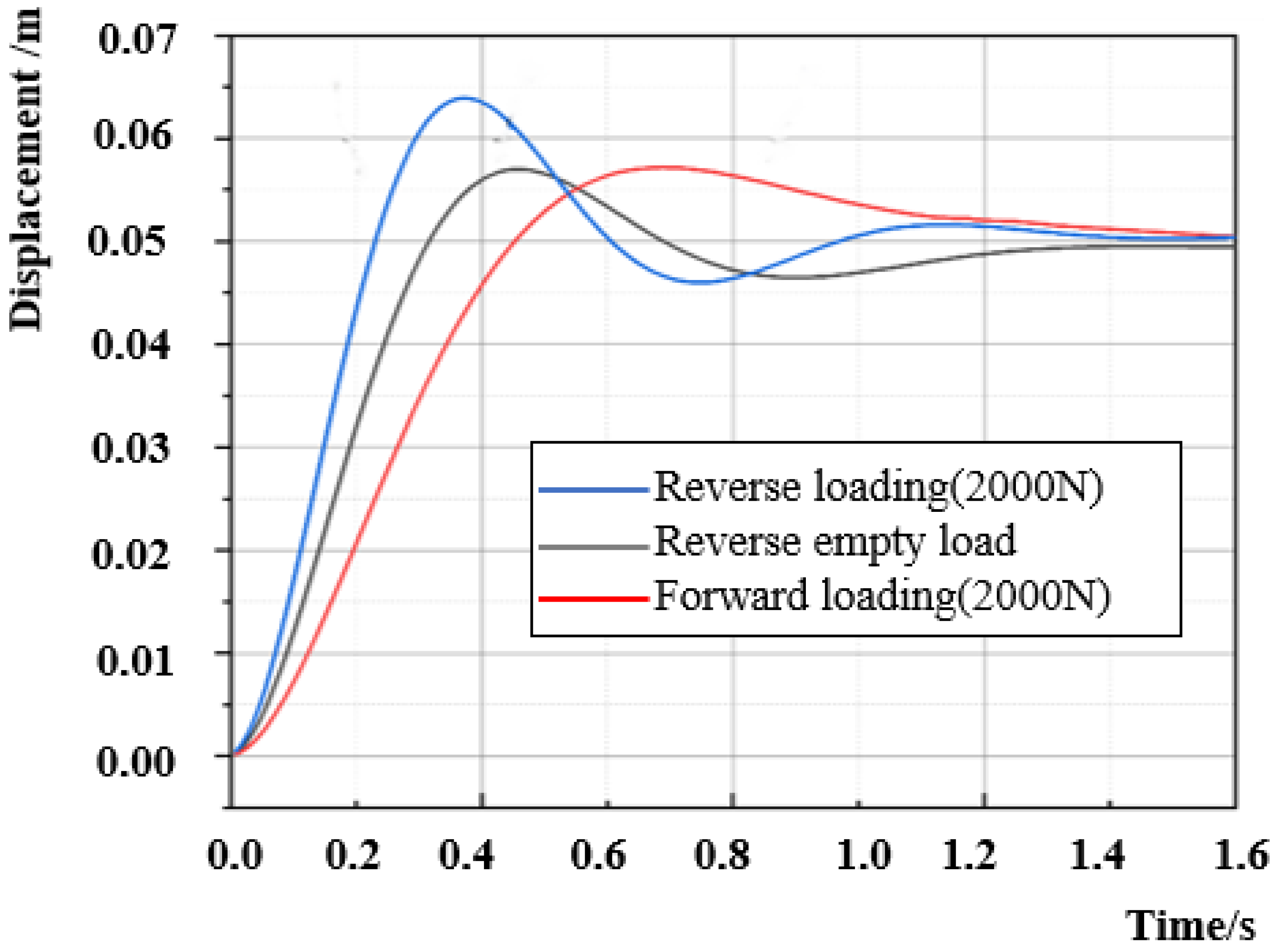
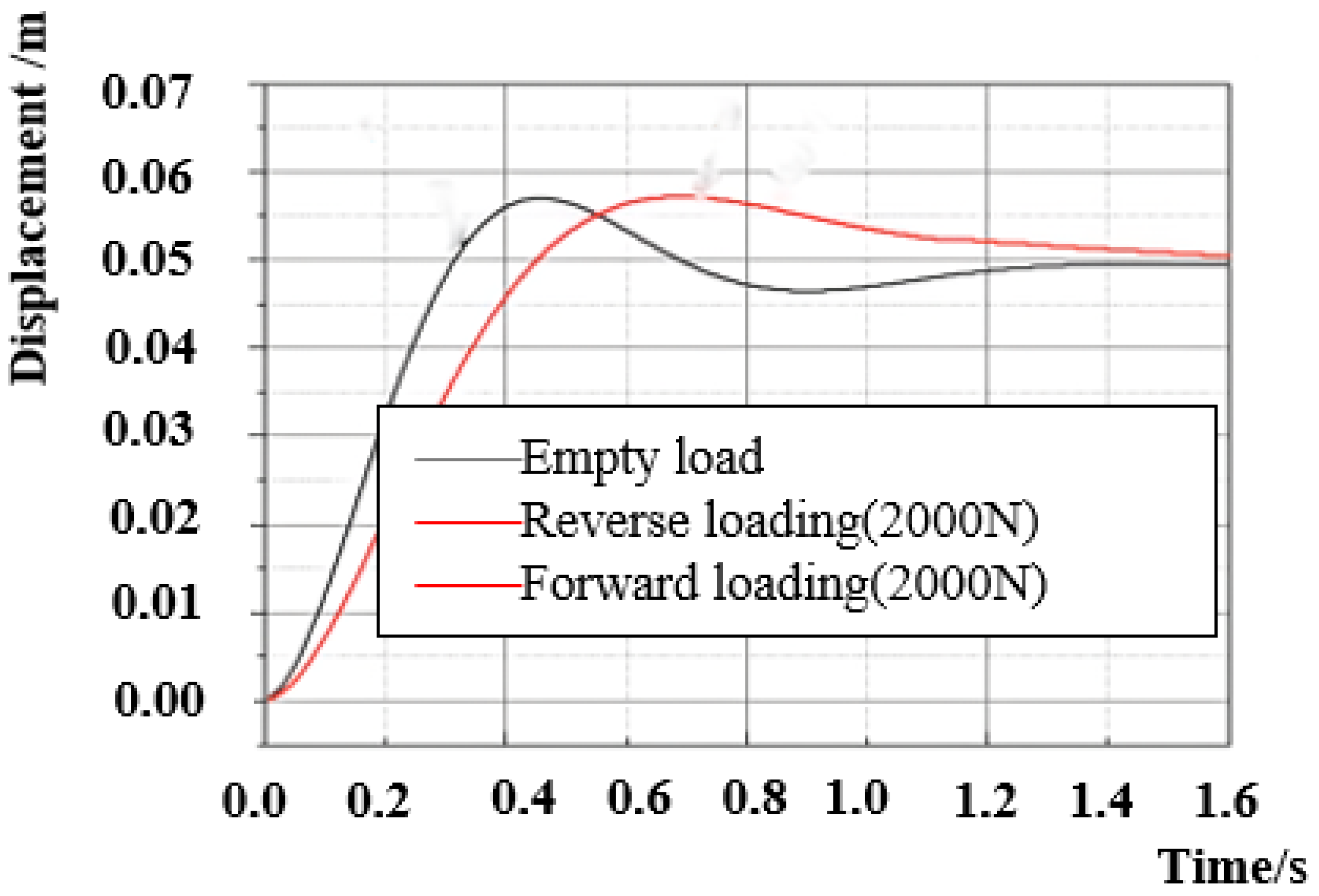
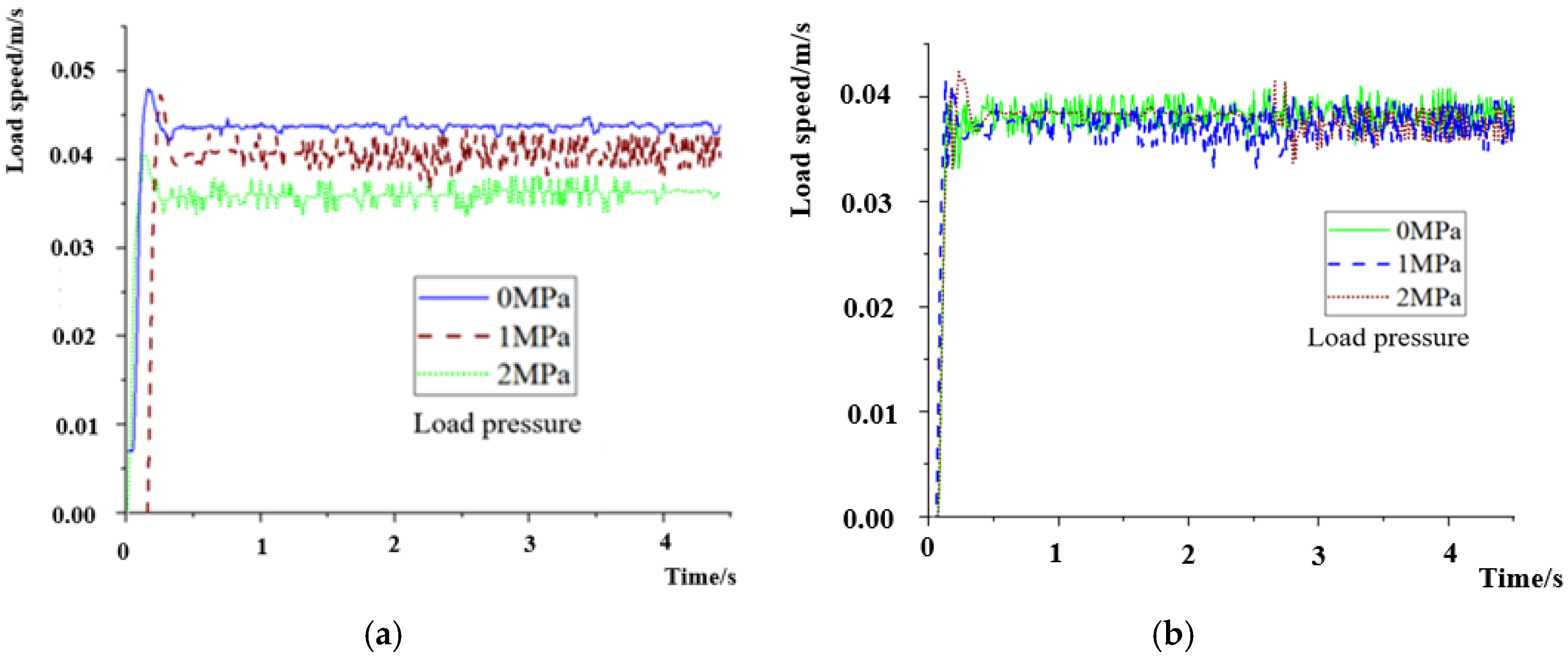
3.1.2. Influence of Asymmetric External Load on Dynamic Characteristics

Figure 4 shows an analysis of the dynamical response curve of a symmetrical hydraulic cylinder system under asymmetric external load forces. The black curve shows the dynamical response of hydraulic cylinder displacement under no-load conditions. The blue curve is the reverse motion curve of the hydraulic cylinder with 2000 N of pressure. The reverse curve shifts to the left of the no-load curve, with a higher response speed and shorter response time. The red curve is the forward motion curve of the hydraulic cylinder with 2000 N of pressure. The forward motion curve shifts to the right on the basis of the no-load curve, with a lower response speed.
The analysis in Section 2.1 and Section 2.2 shows that whether the external loads are identical in both the forward and reverse directions or completely symmetric hydraulic cylinders are used, a consistent response of hydraulic cylinder displacement in both directions cannot be guaranteed. Therefore, the inconsistent dynamic response of hydraulic cylinder displacement in valve-controlled hydraulic systems in both the forward and reverse directions is the result of the combined effect of asymmetric loads and the structural parameters of the hydraulic cylinder itself. As long as one asymmetry exists, the dynamic characteristics will be inconsistent in both directions of the system.

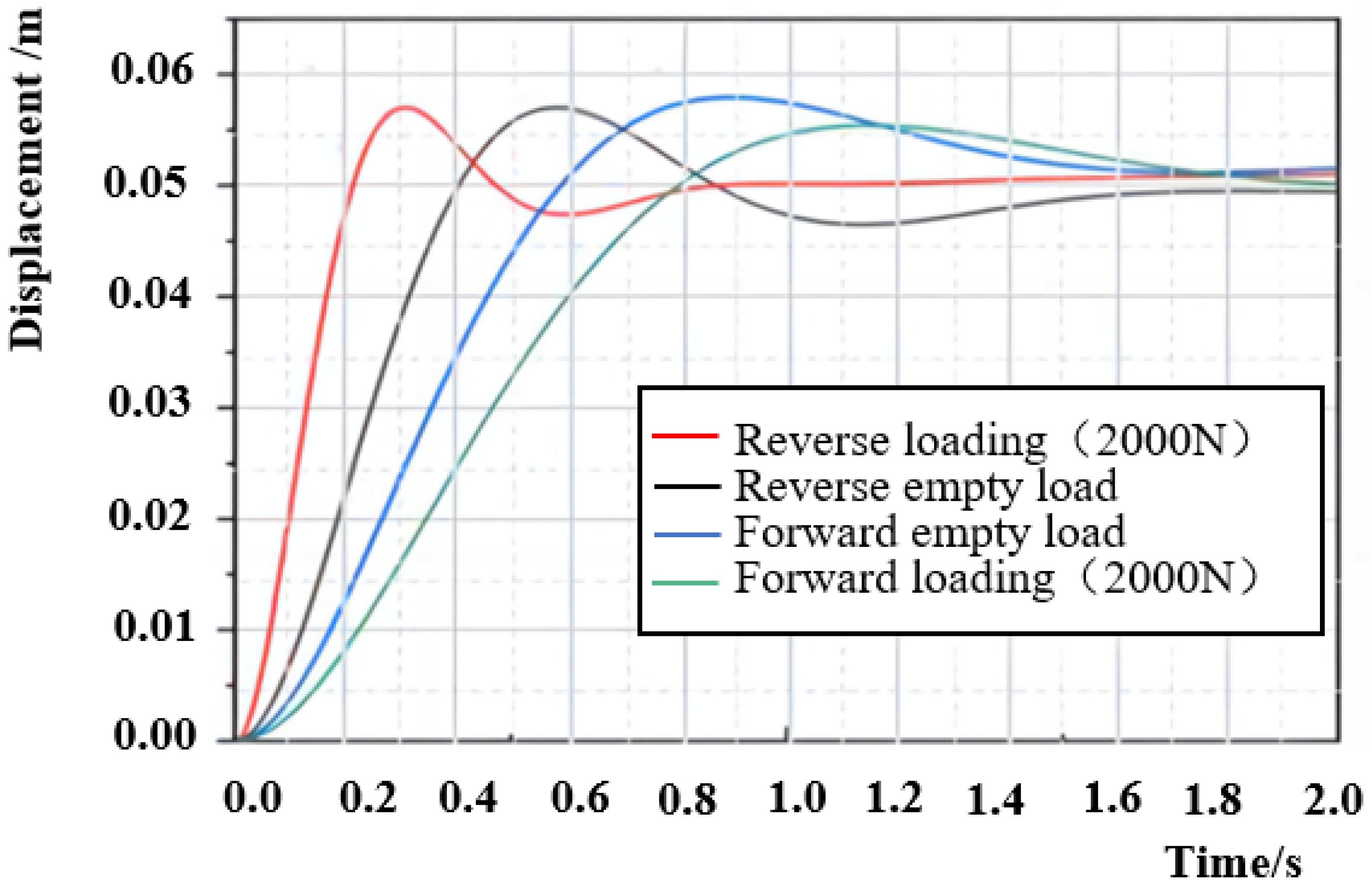
3.1.3. Asymmetric Dynamic Characteristics of Systems Under Coupling Effects

Figure 5 shows the displacing characteristics of the hydraulical cylinder in the forward and reverse directions under no load, with tensile forces of 500 N and 2000 N. The forward velocity under no load is lower than that under load, and when the tensile force is greater, the forward motion curve is farther left. The quicker the speed increases, the shorter the response time, and the greater the increase in load is, the shorter the response time. The reverse speed with no load is greater than the reverse speed with a load, and as the tension increases, the reverse motion curve shifts to the right, indicating a decrease in speed and a longer response time. The greater the load is, the longer the response time.
Figure 6 shows the forward and reverse displacement characteristics of the hydraulic cylinder under no-load conditions, with the forward and reverse displacement characteristic curves under a pressure of 2000 N. After applying a pressure load, the forward curve shifts from black curve to green curve, and the forward velocity under no load is greater than that under a load. As the load increases, the forward displacement curve shifts significantly to the right. The speed gain decreases, and the motion speed decreases. The reverse curve shifts from blue curve to red curve, and the unloaded reverse speed is lower than the loaded reverse speed. With the load increasing, the reverse displacement curve shifts significantly to the left, indicating an increase in the motion speed.
Comparing Figure 5 and Figure 6, it can be seen that due to the asymmetric characteristics of the system, the displacement response characteristics of the hydraulic cylinder under tensile load and compress load are not consistent even with the same load force of 2000 N. Under tensile load, the response time under forward loading is shorter than that under no-load, and the response time under reverse loading is longer than that under no-load. However, under compress load, the response time under reverse loading is shorter than that under no-load, and the response time under forward loading is longer than that under no-load. So under the influence of coupling laws, the forward and reverse characteristic curves of asymmetric hydraulic cylinder systems cannot coincide.

3.2. Symmetric Controller System Design Based on State Feedback

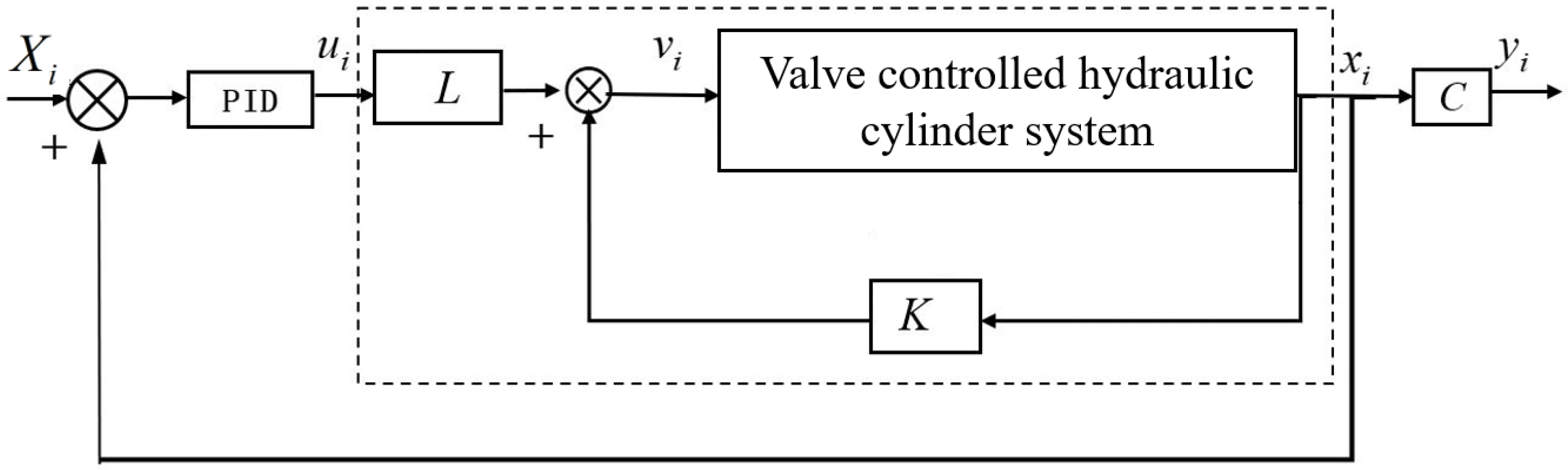
3.2.1. Symmetric Controller System Design

To overcome the drawbacks of inconsistent forward and backward directions in asymmetric systems and avoid overly complex system parameter adjustments, this paper proposes state feedback-based asymmetric valve-controlled hydraulic system symmetric control. To obtain a system symmetric controller, according to the definition of the status space symmetric system, the symmetric response matrix and compensating matrix of Equation (6) need to be obtained. Therefore, Equation (6) is rewritten as follows:
x ˙ 1 x ˙ 2 x ˙ 3 = 0 A 1 m A 2 m β e A 1 V 1 β e V 1 ( K c 1 + C i c + C e c ) β e V 1 K c 1 β e V 2 A 2 β e V 2 ( n K c 1 C e c ) β e V 2 ( C i c + n K c 1 ) x 1 x 2 x 3 + 0 1 m β e V 1 C d 0 β e V 2 n C d 0 u 1 u 2 y 1 y 2 = 1 0 0 0 1 0 x 1 x 2 x 3 That   is : x ˙ = A x + B u y = C x
Then, the matrix expressions of the system can be derived from Equation (7) as follows:
The state matrix A:
A = 0 A 1 m A 2 m β e A 1 V 1 β e V 1 ( K c 1 + C i c + C e c ) β e V 1 K c 1 β e V 2 A 2 β e V 2 ( n K c 1 C e c ) β e V 2 ( C i c + n K c 1 ) .
The control matrix B:
B = 0 1 m β e V 1 C d 0 β e V 2 n C d 0 .
and the output matrix C:
C = 1 0 0 0 1 0 .
According to the criterion for the status space symmetric systems, the existence of a state feedback control law v = k x + L u makes a closed-loop system (8) a status space symmetric system.
x ˙ = ( A + B K ) x + B L u y = C x
According to the definition of a state space symmetric system, the necessary and sufficient condition for system (8) to be a state space symmetric system is
A + B K = ( A + B K ) T B L = C T
Solving the above matrix equation system yields
K = V 1 2 S 1 U 1 T A T A U 1 + Z S S 1 U 1 T A T A U 2 U T L = B C T
where Z is an arbitrary symmetric matrix of the corresponding dimension and the singular value decomposition of B T is B T = V S O U 1 U 2 according to Equation (11).
b 11 b 21 b 31 b 12 b 22 b 32 = v 11 v 12 v 21 v 22 σ 1 0 0 0 σ 2 0 u 11 u 21 u 31 u 12 u 22 u 32 u 13 u 23 u 33
The necessary and sufficient condition for systematic stability is U 2 T A U 2 < 0 .
The control block diagram of the symmetric system is shown in Figure 7. Xi is the ideal state vector, and A–C are the state matrix, control matrix, and output matrix, respectively. K is the feedback matrix, L is the feedforward matrix, and the control parameters for K and L are obtained from Equation (8). By comparing the difference between the ideal state variables and the collected actual state variables, the appropriate input variable ui is obtained, and the transformed input variable vi is obtained through the feedforward and feedback loops. Since K and L are calculated based on the definition of a symmetric system, after adding K and L to the input, the original asymmetric system (7) is transformed into a symmetric system (8), and the part enclosed by the dashed box in the figure satisfies the symmetric system.

3.2.2. System Symmetry and Stability Verification

By substituting the simulation parameters of the hydraulic press control system into Equation (7) to verify the symmetry of the system, the status space of the system can be expressed as shown in Equation (12):
x ˙ 1 x ˙ 2 x ˙ 3 = 0 3.0155 × 10 - 5 0 . 0091 5 . 0919 × 10 9 58 . 579 10.2237 3.0551 × 10 9 7.9211 9 . 364 × 10 11 x 1 x 2 x 3 + 0 0.0091 9 . 364 × 10 11 0 5 . 618 × 10 11 0 u 1 u 2
y 1 = x 1 y 2 = x 2
The system state matrix A is 0 3.0155 × 10 - 5 0 . 0091 5 . 0919 × 10 9 58 . 579 10.2237 3.0551 × 10 9 7.9211 9 . 364 × 10 11 . The control matrix B is 0 0.0091 9 . 364 × 10 11 0 5 . 618 × 10 11 0 , and the output matrix C is 1 0 0 0 1 0 .
According to Equation (8), the feedback control matrix K and the feedforward control matrix L must be obtained, and the singular value decomposition matrices V, S, and U of B T must be obtained. A suitable real symmetric matrix Z must be obtained. The generalized inverse matrix B of B must be obtained.
First, the feedback matrix K is calculated. Singular value decomposition is performed on B T ; singular value matrix decomposition is performed on B T = V S O U T = V S O U 1 T U 2 T ; V, S, and U are calculated; and Z satisfies the conditions. S , U , V , Z , U 1 , U 2 , U 1 T , S 1 and Z are substituted into Equation (8) to obtain K = 0.0013 93.6404 56.1842 9.599 × 10 5 4.2836 × 10 11 4.1518 × 10 11 .
A solution for the feedforward matrix L is determined. To find a suitable L for B L = C T given that B = 0 0.0091 9 . 364 × 10 11 0 5 . 618 × 10 11 0 , C = 1 0 0 0 1 0 is calculated. L = 0 7.8523 × 10 13 110.01 4.8855 × 10 14 .
The control loop shown in Figure 8 is replaced with the obtained feedback matrix K and feedforward compensation matrix L. The hydraulic press control system after state feedback symmetry control satisfies the judgement principle of the status space symmetric system A + B K = ( A + B K ) T , B L = C T .
According to the stability judgement criteria of the status space symmetric systems in Section 3.1, substituting U 2 T , A , U 2 into U 2 T A U 2 yields U 2 T A U 2 < 0 . Thus, the system is stable.

3.2.3. Consistent Responsiveness of System Dynamic Characteristics

A simulation study is performed on the uniform response characteristics in the forward and reverse directions with a load. Figure 8 shows the displacement response of the asymmetric hydraulic cylinder under zero load after state feedback symmetric control of the system. Under no-load conditions, the forward motion response curve, and the reverse motion response curve, of the asymmetric hydraulic cylinder coincide after symmetric control, and the forward and reverse response times and overshoot are essentially the same.
A simulation study is performed on the uniform response characteristics of symmetric hydraulic cylinder loading in both the forward and reverse directions. Figure 9 shows the displacement dynamical response of the symmetrical hydraulic cylinder system under an asymmetric load after state feedback symmetry control. The black curve shows the dynamical response of the system under no-load conditions, The red curve is the reverse motion curve after a 2000 N tensile load is applied to the hydraulic cylinder, and it coincides with the forward motion curve after a 2000 N pressure load is applied to the hydraulic cylinder. For the same magnitude of load force, the symmetric cylinder has a symmetric dynamic response in the forward and reverse directions of the system after symmetric control.
A simulation study is performed on the consistent positive and negative responses of asymmetric hydraulic cylinder coupling. The following six operating conditions are applied to the system after state feedback symmetric control: (1) positive motion when unloaded; (2) reverse motion when unloaded; (3) positive motion under a tensile load of 2000 N; (4) reverse motion under a tensile load of 2000 N; (5) positive motion under a pressure load of 2000 N; and (6) reverse motion under a pressure load of 2000 N.
Simulation studies were conducted on the displacement of hydraulic cylinders under the six working conditions mentioned above, and the displacement response characteristic curves under the six conditions are shown in Figure 10. Figure 10 shows that the no-load forward displacement curve, coincides with the no-load reverse displacement curve; the tensile load forward motion curve, coincides with the compressive load reverse motion curve; and the tensile load reverse motion curve, coincides with the compressive load forward motion curve. After state feedback symmetric control, the displacement of the hydraulic cylinder in the system under coupling has a consistent response in both the forward and reverse directions.

3.3. Experimental Verification

To check the effectiveness of the status feedback-based symmetric control method for asymmetric hydraulic systems and to verify the stability of the system’s operating characteristics and the consistency of the system’s forward and reverse response characteristics using this method, an experimental simulation device for asymmetric valve-controlled hydraulic systems was built. The system experiment was conducted on the device.

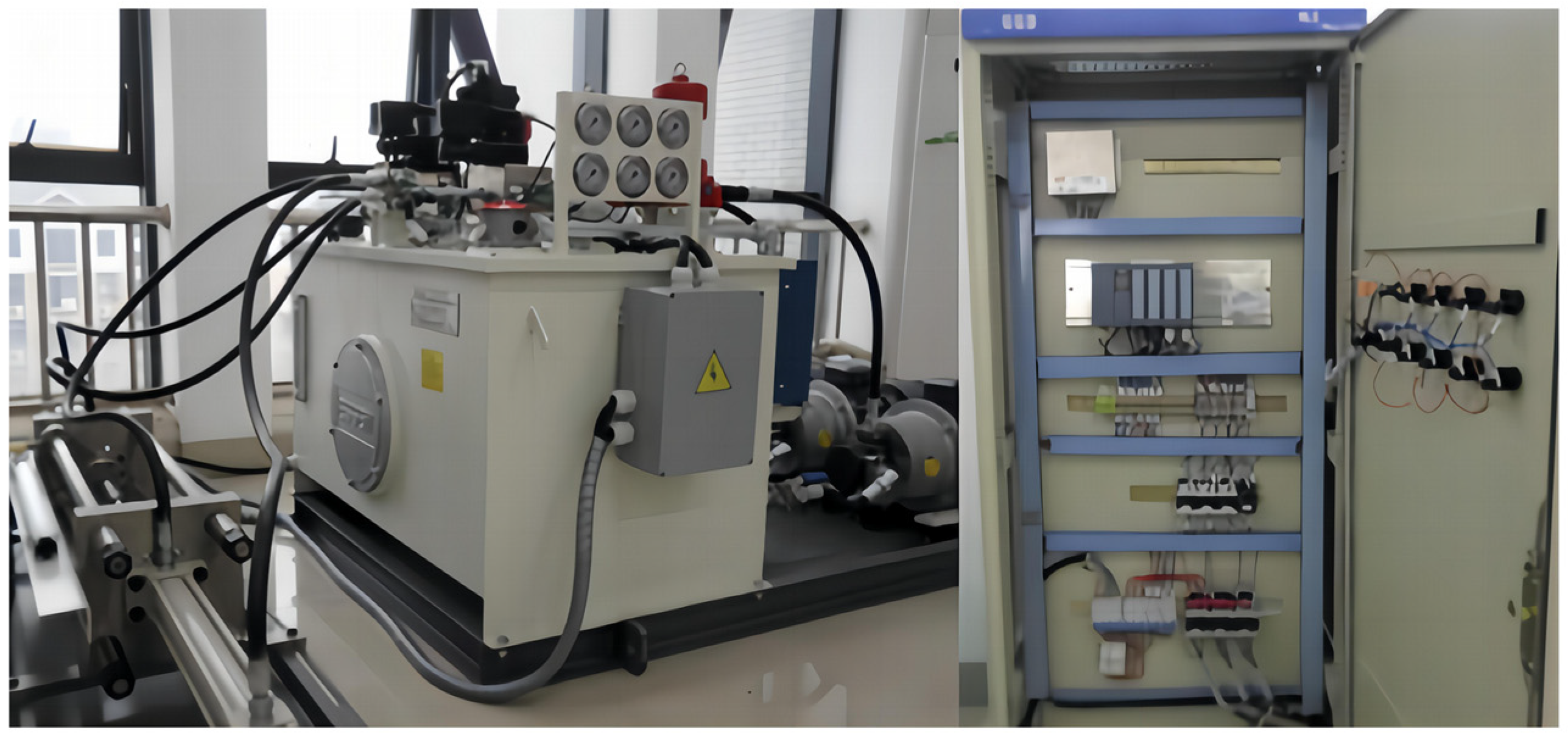
3.3.1. Introduction to Experimental Equipment

According to the simulation analysis results of the hydraulic system under typical conditions, the final experimental platform for the large-scale hydraulic press control system is shown in Figure 11. The proportional valve used is a positive opening proportional valve from Atos Company (DLHZO-TE-040-L71/I).
A sketch map of the experimental hydraulic system is shown in Figure 12. The power system is controlled by a proportional valve, and the load system is controlled by a proportional relief valve. The load system uses two hydraulic pumps to separately supply oil to two load cylinder chambers, making it easy to quickly establish an external load force. The pressures in the left and right chambers of the load cylinder can be controlled by setting the pressure of the proportional relief valve in Figure 12 to simulate forward and reverse loads. The current signal of the proportional reversing valve can be set to adjust the displacement of the proportional relief valve spool.

3.3.2. Basic Experimental Parameters

The experimental parameters are shown in Table 2 according to engineering practice requirements and laboratory product models.

3.3.3. Experimental Methods and Steps

Because the speed of the piston rod movement is not constant and the signal of the given proportional relief valve converted by the given load force is a constant value, the actual relief pressure varies with the speed of the piston rod, making it difficult to maintain a constant pressure value in the left and right chambers of the load cylinder, and the load pressure of the system also changes accordingly. Therefore, closed-loop control of the pressure in the two chambers of the load cylinder was applied to meet the experimental requirements for steady load pressure.
Experimental content: The system pressure is adjusted to 6 MPa, and the state variables, input variables, and output variables are consistent with those described in Section 2.2. The testing system uses the original PID control method and the symmetric control method based on state feedback to study the speed response characteristics of the system. The experimental steps are as follows: (1) The pressure of the electromagnetic overflow valve is adjusted such that the system pressure is 6 MPa. (2) Given load pressures of 0, −1, and 2 MPa and a proportional valve signal of 0.4 in the reverse range, to control the displacement of the valve core to 0.002 m, asymmetric PID control and unified PID control after state space symmetry conversion are used. Every 10 ms, the movement speed (load speed) of the master cylinder piston rod is tested. (3) Given load pressures of 2 MPa, and a proportional valve signal of 0.4 in the forward direction, to control the displacement of the valve core to 0.002 m, asymmetric PID control and unified PID control after state space symmetry conversion are used. Every 10 ms, the motion speed (load speed) of the master cylinder piston rod is tested.

3.3.4. Experimental Results and Analysis

When the original asymmetric PID control of the system is used, the speed characteristic curve of the system is as shown in Figure 13a. When unified PID control is used after state space symmetry transformation, the speed characteristic curve of the system is as shown in Figure 13a.
Figure 13 shows that before symmetric transforming control, when the load pressure is variable and the proportional valve opening remains constant (the theoretical input flow rate remains constant), the system speed varies with different load pressures. As shown in Figure 13a, under positive load pressure, as the load pressure increases, the velocity gradually decreases from 0.044 m/s under no-load conditions to 0.041 m/s under load of 1 MPa and to 0.037 m/s under load of 2 MPa, with an error of 0.007 m/s. The asymmetric characteristics are very obvious. When using state feedback-based symmetry control, as shown in Figure 13b, under no-load, 1 MPa, and 2 MPa load pressures, the velocity fluctuates around 0.040 m/s, with a total error value of about 0.002 m/s, and the response time is within 0.15 s. The velocity characteristics under different loads are basically the same.
Figure 14 shows the velocity response of the system before and after symmetrical control under the same load pressure of 2 MPa.
When the system does not adopt symmetrical control strategy, as shown in Figure 14a, the forward velocity is 0.0358 m/s and the reverse velocity is 0.0397 m/s, so the error is 0.0039 m/s and the difference is very significant. After adopting the symmetrical control strategy, as shown in Figure 14b, the velocities are all 0.0385 m/s. The minor fluctuations and basically consistent velocity characteristics indicate that the symmetric control based on the state feedback strategy can adjust the speed of the forward and reverse directions to be basically consistent.
Experiments have shown that due to the influence of asymmetric factors such as structure, external load, friction, damping coefficient, and natural frequency, when the system adopts the original PID control strategy and sets the proportional valve opening degree to a certain value, different load pressures will result in different load speeds. And under the same load pressure, the dynamic characteristics of the forward and reverse speed are not consistent, which makes it difficult to ensure the control accuracy of the load speed. After adopting the state feedback-based symmetric control strategy, the system is transformed into a state space symmetric system. When the proportional valve opening is set to a certain value, under the closed-loop action of the feedback controller K and the feedforward controller L, as shown in Figure 15, the system will automatically adjust the proportional valve opening to a suitable position, so that the system has input–output symmetry and consistency in forward and reverse dynamic characteristics. Therefore, the load speed error is greatly reduced under different load pressures, and the forward and reverse speed response characteristics are basically the same under the same load pressure.

4. Conclusions

This paper investigates the symmetric control issue of a type of valve-controlled hydraulic system on the basis of state feedback, analyzes the influence of the asymmetric dynamical characteristics of valve-controlled hydraulic systems, and designs a symmetric controller on the basis of state feedback. Through a simulation and experimental analysis, the conclusions are as follows.
(1) The dynamic characteristics of the system are inconsistent in both the forward and reverse directions before symmetric control. The forward response time is shorter and the overshoot is greater than that under no load, while the reverse response time was longer and the overshoot was smaller than that under no load. After symmetric control, the dynamic characteristic curves of the system under no load, 500 N applied in both directions, and 2000 N applied in both directions completely overlapped, proving that the system achieves the symmetric transformation.
(2) The nonuniform dynamic response of the valve-controlled asymmetric hydraulic cylinder system in both the forward and reverse directions was verified through AMSim simulations, and the coupling effect between the system load and the asymmetric structural parameters of the hydraulic cylinder was obtained.
(3) The feedforward matrix and feedback matrix of the system with symmetric control were obtained, verifying the symmetry and stability of the system after applying the symmetric controller.
(4) After a state feedback-based symmetric controller is applied to the valve-controlled asymmetric hydraulic cylinder system, the system exhibited consistent dynamical response characteristics in both the forward and reverse directions.
(5) Through experiments, before symmetric control, the system records the load velocity at load pressures under constant proportional control valve opening. Regardless of forward or reverse loading, the higher load pressure leads to a lower speed. After symmetric control, the forward and reverse velocity characteristic curves of the system are basically consistent under changes in the load pressure.
(6) This paper analyzes the composite characteristics of asymmetric factors such as the load, structure, and response of complex equipment hydraulic systems, and proposes a state feedback-based asymmetric valve-controlled hydraulic system symmetry conversion control theory and method to solve key problems such as complex system control strategies and numerous control parameters caused by the inconsistent dynamic characteristics of hydraulic cylinders in the two directions of extension and contraction in complex equipment systems.

Author Contributions

Conceptualization, Y.W.; Methodology, S.T., Q.L., J.T., Y.S. and S.S.; Software, Y.W.; Validation, S.T., J.T. and Y.S.; Formal analysis, J.T.; Investigation, Y.W. and S.S.; Data curation, Y.S. and S.S.; Writing – original draft, Y.W., S.T., Q.L. and S.S.; Writing – review & editing, Q.L., J.T. and Y.S.; Visualization, Q.L.; Funding acquisition, Q.L. and J.T. All authors have read and agreed to the published version of the manuscript.

Funding

This work was supported in part by the Guangxi Science and Technology Major Program (No. 2024AA26001) and the Natural Science Foundation of Hunan Province (No. 2023jj30185) and the Scientific Research Fund of Hunan Provincial Education Department (No. 22A0640).

Data Availability Statement

The original contributions presented in this study are included in the article. Further inquiries can be directed to the corresponding authors.

Conflicts of Interest

The authors declare no conflict of interest.

References

  1. Kim, S.W.; Cho, B.; Shin, S.; Oh, J.H.; Hwangbo, J.; Park, H.W. Force Control of a Hydraulic Actuator with a Neural Network Inverse Model. IEEE Robot. Autom. Lett. 2021, 6, 2814–2821. [Google Scholar] [CrossRef]
  2. Kosek, M.; Downar, D.; Sliwinski, P. Hydraulic valve design methodology for hydro turbine control system. Flow Meas. Instrum. 2024, 100, 102718. [Google Scholar] [CrossRef]
  3. Zhang, Q.; Song, X.; Song, S.; Stojanovic, V. Finite-Time sliding mode control for singularly perturbed PDE systems. J. Frankl. Inst. 2023, 360, 841–861. [Google Scholar] [CrossRef]
  4. Coskun, G.; Kolcuoglu, T.; Dogramacı, T.; Turkmen, A.C.; Celik, C.; Soyhan, H.S. Analysis of a priority fow control valve with hydraulic system simulation model. J. Braz. Soc. Mech. Sci. Eng. 2017, 39, 1597–1605. [Google Scholar] [CrossRef]
  5. Djordjevic, V.; Tao, H.; Song, X.; He, S.; Gao, W.; Stojanovic, V. Data-driven control of hydraulic servo actuator: An event-triggered adaptive dynamic programming approach. Math. Biosci. Eng. 2023, 20, 8561–8582. [Google Scholar] [CrossRef]
  6. Li, X.; Zhu, Z.C.; Rui, G.C.; Cheng, D.; Shen, G.; Tang, Y. Force Loading Tracking Control of an Electro-Hydraulic Actuator Based on a Nonlinear Adaptive Fuzzy Backstepping Control Scheme. Symmetry 2018, 10, 155. [Google Scholar] [CrossRef]
  7. Fresia, P.; Rundo, M.; Padovani, D.; Altare, G. Combined speed control and centralized power supply for hybrid energy-efficient mobile hydraulics. Autom. Constr. 2022, 140, 104337. [Google Scholar] [CrossRef]
  8. Schonborn, A.; Chantzidakis, M. Development of a hydraulic control mechanism for cyclic pitch marine current turbines. Renew. Energy 2007, 32, 662–679. [Google Scholar] [CrossRef]
  9. Lyu, L.; Chen, Z.; Yao, B. Development of Pump and Valves Combined Hydraulic System for Both High Tracking Precision and High Energy Efficiency. IEEE Trans. Ind. Electron. 2019, 66, 7189–7198. [Google Scholar] [CrossRef]
  10. Zang, W.S.; Zhang, Q.; Su, J.P.; Feng, L. Robust Nonlinear Control Scheme For Electro-Hydraulic Force Tracking Control with Time-Varying Output Constraint. Symmetry 2021, 13, 2074. [Google Scholar] [CrossRef]
  11. Ko, Y.R.; Kim, T.H. Feedforward Plus Feedback Control of an Electro-Hydraulic Valve System Using a Proportional Control Valve. Actuators 2020, 9, 45. [Google Scholar] [CrossRef]
  12. Liu, W.; Xu, B.; Yang, H.Y.; Zhao, H.F.; Wu, J.H. Hydraulic operating mechanisms for high voltage circuit breakers Progress evolution and future trends. Sci. China Technol. Sci. 2011, 54, 116–125. [Google Scholar] [CrossRef]
  13. Zhao, W.S.; Wang, X.; Jiang, Z.; Long, Y.F. A Gain Scheduling Design Method of the Aero-Engine Fuel Servo Constant Pressure Valve with High Accuracy and Fast Response Ability. Symmetry 2023, 15, 45. [Google Scholar] [CrossRef]
  14. Wei, H.E.; Huang, J.H.; Hao, H.M. Design and Analysis of a Swashplate Control System FOR an Asymmetric Axial Piston Pump. J. Dyn. Syst. Meas. Control 2020, 142, 26–33. [Google Scholar]
  15. Emelyanov, R.T.; Klimov, A.S.; Kravtsov, K.S.; Olenev, I.B.; Turysheva, E.S. Improving the efficiency of a hydraulic drive with a closed-loop hydraulic circuit. J. Phys. 2020, 1515, 042078. [Google Scholar] [CrossRef]
  16. Guo, L.; Xu, C.; Yu, T.H.; Wumaier, T. An improved mayfly optimization algorithm based on median position and its application in the optimization of PID parameters of hydro-turbine governor. IEEE Access 2022, 10, 36335–36349. [Google Scholar]
  17. Kumar, S.; Tewari, V.K.; Bharti, C.K.; Ranjan, A. Modeling, simulation and experimental validation of flow rate of electro-hydraulic hitch control valve of agricultural tractor. Flow Meas. Instrum. 2021, 82, 102070. [Google Scholar] [CrossRef]
  18. Jensen, K.J.; Ebbesen, M.K.; Hansen, M.R. Novel Concept for Electro-Hydrostatic Actuators for Motion Control of Hydraulic Manipulators. Energies 2021, 14, 6566. [Google Scholar] [CrossRef]
  19. Zhang, W.; Yuan, Q.H.; Xu, Y.F.; Wang, X.G.; Bai, S.Z.; Zhao, L.; Hua, Y.; Ma, X.X. Research on Control Strategy of Electro-Hydraulic Lifting System Based on AMESim and MATLAB. Symmetry 2023, 15, 435. [Google Scholar] [CrossRef]
  20. Liu, A.L.; Li, S.L.; Yu, H.L. Research on synchronous control of dual cylinder hydraulic system based on fuzzy theory. Hydraul. Pneum. 2016, 4, 44–47. [Google Scholar]
  21. Guo, Q.; Yu, T.; Jiang, D. Robust H positional control of 2-DOF robotic arm driven by electro-hydraulic servo system. ISA Trans. 2015, 59, 55–64. [Google Scholar] [CrossRef]
  22. Wu, W.; Yu, C.Y. Simulation and Experimental Analysis of Hydraulic irectional Control for Displacement Controlled System. IEEE Access 2018, 6, 27993–28000. [Google Scholar] [CrossRef]
  23. Guo, K.; Wei, J.H.; Fang, J.H. Position tracking control of electro-hydraulic single-rod actuator based on anextended disturbance observer. Mechatronics 2015, 27, 47–56. [Google Scholar] [CrossRef]
  24. Ding, R.Q.; Zhang, J.H.; Xu, B.; Cheng, M. Programmable hydraulic control technique in construction machinery: Status, challenges and countermeasures. Autom. Constr. 2018, 95, 172–192. [Google Scholar] [CrossRef]
  25. Liu, M.; Lin, H.; Wang, Y.; Chen, G. Negative imaginariness and positive realness analysis of state-space symmetric systems with interval uncertainty. Proc. Inst. Mech. Eng. 2022, 236, 792–799. [Google Scholar] [CrossRef]
  26. Kong, X.D.; Cai, B.P.; Liu, Y.H.; Zhu, H.M.; Liu, Y.Q.; Shao, H.D.; Yang, C.; Li, H.J.; Mo, T.Y. Optimal sensor placement methodology of hydraulic control system for fault diagnosis. Mech. Syst. Signal Process. 2022, 174, 109069. [Google Scholar] [CrossRef]
  27. Deng, W.X.; Yao, J.Y.; Wang, Y.Y.; Yang, X.W.; Chen, J.H. Output feedback backstepping control of hydraulic actuators with valve dynamics compensation. Mech. Syst. Signal Process. 2021, 158, 107769. [Google Scholar] [CrossRef]
  28. Piller, O.; van Zyl, J.E. Modeling Control Valves in Water Distribution Systems Using a Continuous State Formulation. J. Hydraul. Eng. 2014, 140, 04014052. [Google Scholar] [CrossRef]
Figure 1. Working principle of the hydraulic system.
Symmetry 17 00246 g001
Figure 2. AMESIM simulation model of a water distributor.
Symmetry 17 00246 g002
Figure 3. Dynamic response characteristics of the asymmetric hydraulic cylinder displacement under zero load.
Symmetry 17 00246 g003
Figure 4. Dynamic response curves of the displacement of a symmetrical hydraulic cylinder with an asymmetric external load.
Symmetry 17 00246 g004
Figure 5. Load characteristics of asymmetric hydraulic cylinder tension.
Symmetry 17 00246 g005
Figure 6. Pressure load characteristics of the asymmetric hydraulic cylinder.
Symmetry 17 00246 g006
Figure 7. Symmetric control block diagram based on state feedback.
Symmetry 17 00246 g007
Figure 8. Zero-load characteristics of the asymmetric hydraulic cylinder after symmetric control.
Symmetry 17 00246 g008
Figure 9. Displacement dynamic response of the symmetric hydraulic cylinder system under an asymmetric load.
Symmetry 17 00246 g009
Figure 10. Displacement response characteristic curves of the asymmetric hydraulic cylinder under different loads.
Symmetry 17 00246 g010
Figure 11. Field picture of the asymmetric valve-controlled hydraulic system experiment. 1. Drive pump; 2. load pump 1; 3. load pump 2; 4. proportional overflow valve 1; 5. proportional overflow valve 2; 6. proportional valves; 7. drive hydraulic cylinders; 8. load hydraulic cylinders.
Symmetry 17 00246 g011
Figure 12. Schematic diagram of the experimental hydraulic system.
Symmetry 17 00246 g012
Figure 13. Velocity response curve of the system under different loads. (a) Before symmetric transformation, and (b) after symmetric transformation.
Symmetry 17 00246 g013
Figure 14. Velocity response curve of the system under same loads. (a) Before symmetric transformation, and (b) after symmetric transformation.
Symmetry 17 00246 g014
Figure 15. The implementation method of symmetrical control in experimental equipment.
Symmetry 17 00246 g015
Table 1. Main simulation parameters.
ParametersValue
Type of hydraulic oilN46
Internal leakage coefficient 3 × 10⁻¹¹ m3/sPa
Hydraulic oil viscosity, viscosity of oil51
Initial volume of the working cylinder 4.9 × 10⁻⁴ m3
The system rated pressure6 MPa
Maximum system flow90 L/min
Effective working area of the rodless cavity0.0169 m2
Effective working area of the rod cavity0.0116 m2
Piston viscous friction coefficient 80 N/(m/s)
Discharge coefficient0.61
Proportional valve flow coefficient2.8961 m2/s
Proportional valve pressure coefficient 6.66 × 10⁻¹² m3/sPa
Effective bulk elastic modulus7 × 108 Pa
Viscous damping coefficient of the piston and load 120
Table 2. Experimental platform parameters.
ParametersSymbols and UnitsNumerical ValueParameterSymbols and UnitsNumerical Value
Hydraulic cylinder volume V t / m 3 0.00057Hydraulic pump pressure P S / MPa 0–6 (adjustable)
Rated pressure of the proportional valve P N / MPa 4Rated flow rate of the proportional valve Q N / ( L / min ) 14
Area of action of the rodless cavity A 1 / m 2 0.001963Elastic bulk modulus of hydraulic oil E / MPa 1. 4 × 10³
Effective area of the rod cavity A 2 / m 2 0.001347Load quality m / kg 110
Rated current of the proportional valve I N / A 0.4Overflow valve pressure P N / MPa 0–6 (adjustable)
Disclaimer/Publisher’s Note: The statements, opinions and data contained in all publications are solely those of the individual author(s) and contributor(s) and not of MDPI and/or the editor(s). MDPI and/or the editor(s) disclaim responsibility for any injury to people or property resulting from any ideas, methods, instructions or products referred to in the content.

