Article

Experimental Study on the Symmetry of the Soil-Arching Effect of a Pile Foundation in a Reinforced High-Fill Area

1
School of Aeronautics and Astronautics, Shanghai Jiao Tong University, Shanghai 200240, China
2
China Railway Changjiang Transport Design Group Co., Ltd., Chongqing 401220, China
3
School of Intelligent Construction, Chongqing College of Architecture and Technology, Chongqing 401300, China
*
Author to whom correspondence should be addressed.
Symmetry 2025, 17(2), 188; https://doi.org/10.3390/sym17020188
Submission received: 2 January 2025 / Revised: 14 January 2025 / Accepted: 22 January 2025 / Published: 25 January 2025
(This article belongs to the Section Engineering and Materials)

Abstract

:
In addition to the vertical external load and soil settlement load, the pile foundation in reinforced high-fill areas is also affected by the horizontal load caused by the rear stacking load, and pile stress is affected by the soil-arching effect in reinforced areas that have typical passive pile characteristics. In order to study the symmetry of the soil-arching effect of pile foundations in a reinforced-fill area, indoor model tests were designed and the relevant data for the pile foundation and reinforced soil under surcharge were obtained. Through the analysis, the following conclusions were drawn: the peak bending moment of the pile body is basically consistent with the position of the potential sliding surface of reinforced soil; the maximum shear force of the pile body appears about 150 mm below the embedding point; with an increase in depth, the soil-arching effect becomes obvious. There are two different forms of friction, soil-arching and direct soil-arching between piles and behind piles, and the soil between single-row piles has a symmetrical distribution. In addition to the vertical external load and soil settlement load, the pile foundation in reinforced high-fill areas will also be affected by the horizontal load caused by the rear stacking load, and pile stress will be affected by the soil-arching effect in reinforced areas, which has typical passive pile characteristics. In order to study the symmetry of the soil-arching effect of pile foundations in a reinforced-fill area, indoor model tests were designed, and the relevant data for pile foundation and reinforced soil under surcharge were obtained. Through analysis, the following conclusions were drawn: (1) the peak bending moment of the pile body is basically consistent with the position of the potential sliding surface of reinforced soil; the maximum shear force of the pile body appears about 150 mm below the embedding point; with an increase in depth, the soil-arching effect becomes obvious. There are two different forms of friction, soil-arching and direct soil-arching between piles and behind piles, and the soil between single-row piles has a symmetrical distribution.

1. Introduction

The mechanical engineering behavior of interactions between soil and pile foundation in reinforced high-fill areas, as well as their deformation and failure mechanisms, are nonlinear and complicated. Based on a theoretical analysis of mathematics and mechanics, a numerical analysis can be conducted, which was established following the development of computational mathematics and the progress made in computer science and technology; this has greatly enriched the research methods.
The soil-arching effect was first proposed by Terzaghi in 1936. Looking back over more than 80 years of research, the research on soil-arching effect mainly focuses on two aspects: the formation mechanism and influencing factors of the soil-arching effect, which are mainly determined using theoretical analyses, model tests and numerical simulations; and, based on the soil-arching effect, the reasonable pile spacing, the ultimate bearing capacity and the overall stability of the slope after reinforcement.
Regarding the soil-arching effect of pile foundations, many scholars have carried out systematic and comprehensive research work, using theoretical analyses, experiments, numerical calculations, and other means, and have achieved rich research results.
Kuang Lixin [1] revised the traditional external stability analysis of soil nailing by using the soil arch theory, studied the maximum horizontal spacing of soil nailing and the maximum excavation height of soil nailing, and put forward a new formula and method of calculation. Chen Zhijun [2] used the three-dimensional finite element method of a typical section to simulate the composite foundation of a tubular pile under an embankment. Zhang Zhuhua et al. [3] determined the pile spacing through the joint control of the static equilibrium condition and the strength condition of a soil arch between piles, and derived a calculation formula to determine the spacing of the supporting piles. Hui Wei [4] established a formula for calculating the reasonable spacing between curtain piles according to the horizontal static equilibrium condition of the arch foot and the strength condition of the triangular compression zone. On the basis of the H&R soil arch model, Zheng Junjie [5] improved the analysis of soil arch effects by including the state coefficient of the vault or the pile topsoil element.
In the above research, soil arches in pile foundations were studied using different methods from different perspectives; however, research on the interaction between reinforced soil and pile foundations is rare.
In this paper, a model test of four pile foundations in a reinforced-fill area during the loading of a back slope top is designed, and the bending moment of the pile body, the pressure of the earth on the side of the pile, and the soil-arching effect are preliminarily discussed.

2. Model Test Scheme
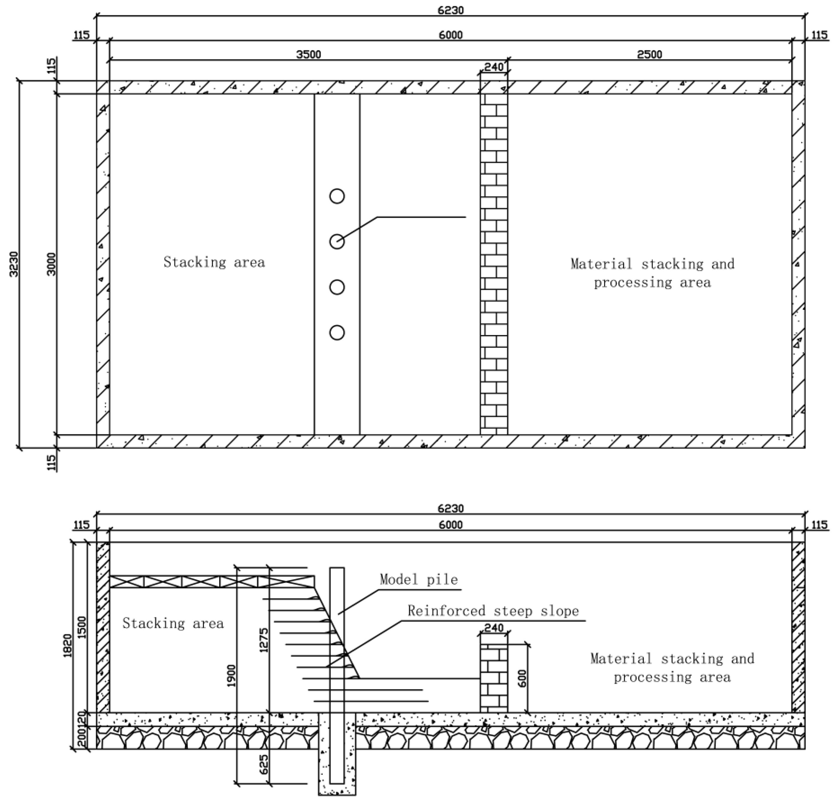
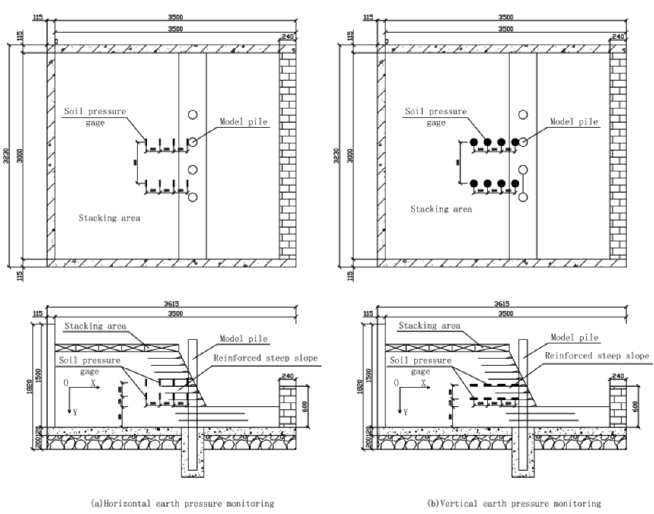
The mechanical engineering behavior of the interactions between the soil and pile foundation in a reinforced high-fill area and their deformation and failure mechanisms are characterized by nonlinearity and complexity. Based on a theoretical, mathematical, and mechanical analysis, a numerical analysis was derived through the development of computational mathematics and computer science and technology, which has greatly enriched the research methods. However, physical tests are still an indispensable means of research, especially those using indoor models based on similarity theory, which have the advantages of being low cost, having a short cycle, and making it easy to find and obtain relevant test data.
In order for the experiment to achieve the expected effect, all aspects of material selection, model pouring, experimental loading, and monitoring data should be strictly proofread, and the method of operation should be confirmed by three different testers.

2.1. Test Program

The main purpose of this study is to focus on the formation mechanism and action scope of the soil-arching effect of a wharf pile foundation in a reinforced high-fill area. The main purpose of the test is to explore the three-dimensional distribution and degree of action of soil-arching in a reinforced high-fill area, and to explore the relationship between the soil-arching effect between piles and the stability of the reinforced soil.
The plane size of the experimental model pool was 6000 mm × 3000 mm, and the depth was 1500 mm. The wall of the pond was supported by a clay brick mortar masonry with a thickness of 240 mm, and the bottom of the pond was leveled using plain concrete with a thickness of 120 mm. As shown in Figure 1.

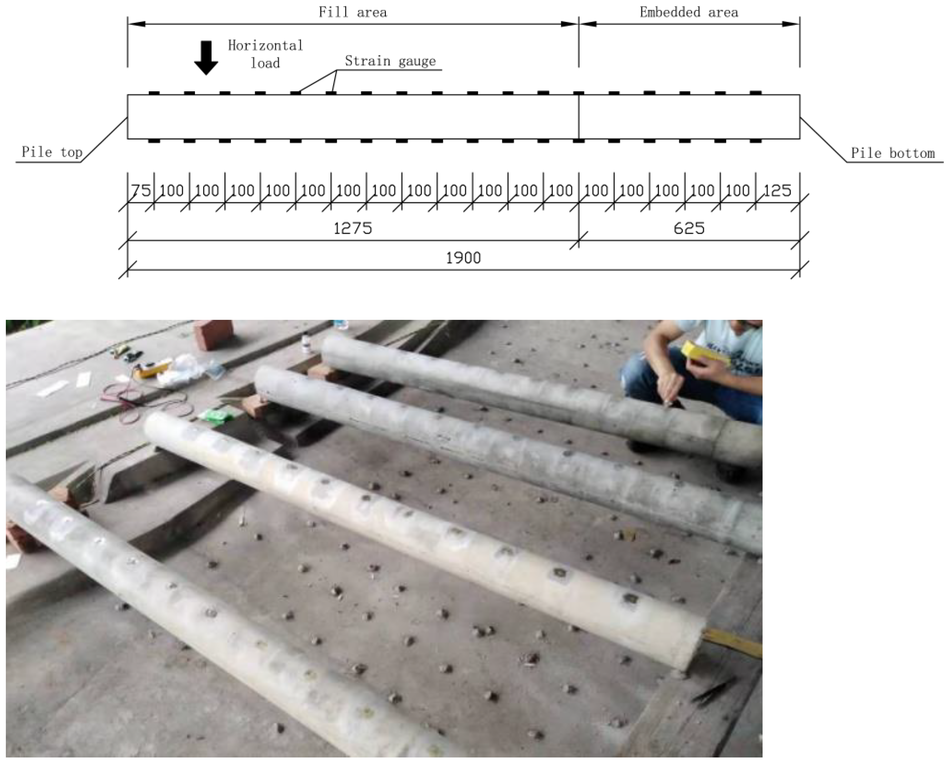
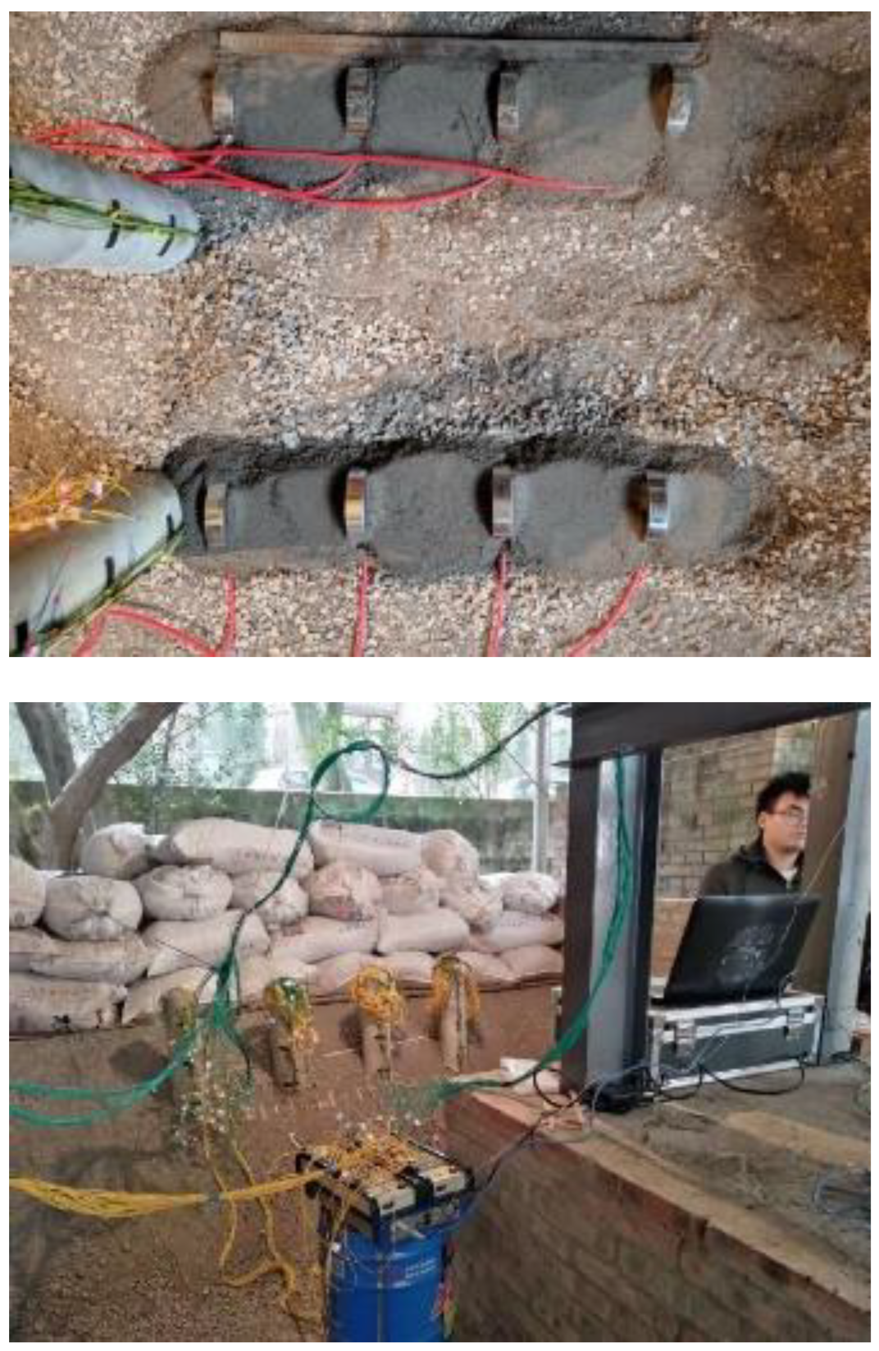
2.2. Model Pile Pouring

The concrete used for the model pile body was C30, and a transparent plastic pipe with an inner diameter of 130 was used as the template for pouring the model pile. The reinforcement was simulated by 8 steel bars, and the diameter of the steel bars was sqrt (98.5 × 4/3.14) = 11.2 mm. As shown in Table 1.
The test model pile is a circular section pile of reinforced concrete, with a diameter of 125 mm and a length of 1900 mm. As shown in Figure 2.
In order to test the change in the curvature of the pile body in the filling section under horizontal load, two rows of strain gauges were symmetrically arranged along the length of the pile with a distance of 150 mm. Eleven pairs of strain gauges were used: seven pairs in the filling section, three pairs in the rock-socketed section, and one pair at the boundary. As shown in Figure 3.

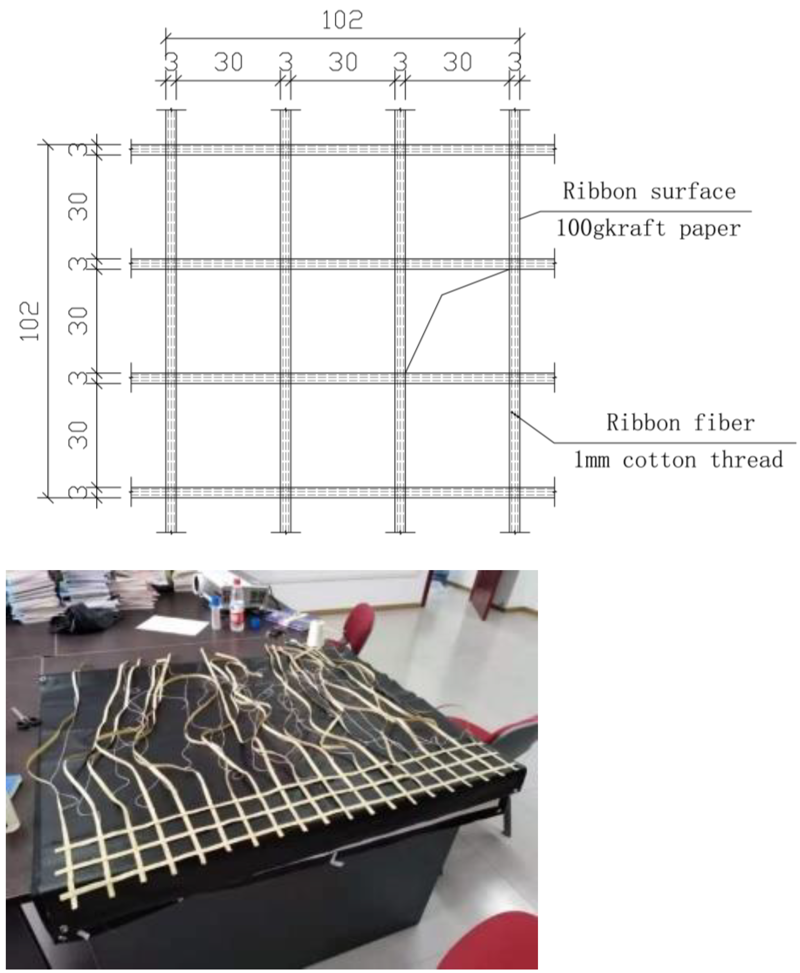
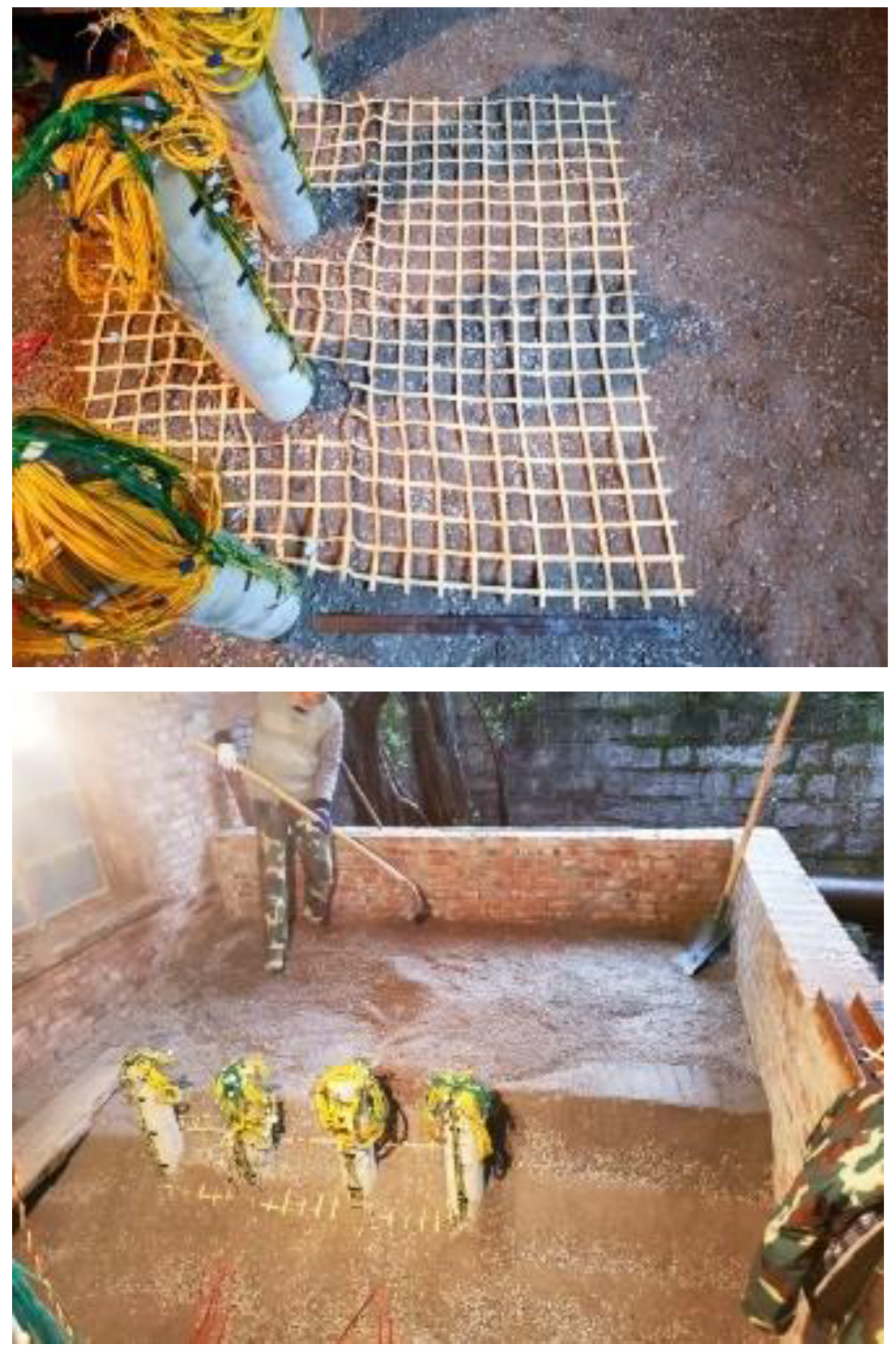
2.3. Fabrication of Reinforced Slope

The filling materials used in the reinforced soil are as follows:
(1)
Cohesive soil, taken from alluvial soil on the terrace of the Chongqing section of the Three Gorges reservoir area of the Yangtze River.
(2)
Stone powder: sand rock powder with particle size of 0.5~3.0 mm was selected.
(3)
Gravel: limestone gravel aggregate with particle size of 14~18 mm was selected.
The model tendon was as follows: width: d = 60/20 = 3.0 mm; ultimate tensile strength: tu = 100/20 = 5.0 kn/m.
According to the above parameters, 100 g kraft paper and 1 mm cotton thread were selected as raw materials to bond the bidirectional model geogrid. As shown in Figure 4.
According to the different proportions of the designed fillers, the fillers were mixed outside the test site in advance, then compacted and used to fill in each layer.
The thickness of each filled layer was 200 mm. After the filler was compacted, a layer of the reinforcement belt was laid and filled to the desired height using a step-by-step process. The reinforcement belt outside the slope was brushed and compacted in reverse according to the designed gradient. As shown in Figure 5.

2.4. Loading and Data Monitoring

In order to simulate the stacking load at the top of the slope, the test adopted the method of placing the sand and gravel in woven bags and stacking them in layers after tying the mouth. The applied load is uniformly distributed and static. As shown in Figure 6.
The stacking volume of each bag was about 0.12 m3, the bulk density of the filler was about 1.5 t/m3, the weight of each bag was about 70 Kg, the stacking area was 2800 mm × 1600 mm, 21 bags were stacked in each layer, and the uniformly distributed load applied by a single layer was 3 Kpa. A total of four layers were stacked.
In order to ensure uniformity among the stacking loads, a layer of blockboard was laid on the top of the slope in order to apply the top stacking load evenly on the model slope.
In the experiment, the loading above the fill slope was carried out using woven bags filled with sandy stones. The weights of five woven bags were measured via electronic scales as 67.5 kg, 63.15 kg, 56.1 kg, 57.7 kg, and 63.05 kg, and the average weight of each woven bag was 61.5 kg. About 20 bags could be placed on each floor, and 4 floors could be stacked, which translates into a uniform load of 10.7 kPa acting on the upper part of the slope. Accordingly, the value of the uniformly distributed load applied above the slope during the numerical simulation was 10.7 kPa. As shown in Figure 7.
The monitoring data measured two aspects:
(1)
A vibrating wire earth pressure gauge with a diameter of 108 mm, a thickness of 26 mm, and a maximum range of 0.2 MPa was used to monitor the earth pressure of the slope in the reinforced high-fill area.
(2)
The stress of the pile foundation in the reinforced high-fill slope area was obtained using a pre-embedded strain.

3. Analysis of Test Results

According to elastic beam theory [6], the model pile can be regarded as a beam structure and the curvature φ z of the pile can be calculated using the following formula according to the difference Δ ε in the strain gauge readings on both sides of the pile when at the same height, which is regarded as a small strain.
φ z = Δ ε a
In the formula:
Z —the vertical distance from the top surface of the model slope to the pile section of the calculation point (m).
a —the model pile used to calculate the vertical distance between the cross section and the pile bottom (m).
Based on the curvature of the pile body and the measured value of the bending stiffness EI (N·m2) of the model pile, the bending moment M(z) at different positions of the pile body can be calculated using the following formula.
M z = E I φ ( z )
The calculation of the earth pressure P z on the side of the pile was based on the differential of the bending moment of the pile, and the deflection curve equation y z of the pile was obtained by integrating the bending moment equation twice.
p z = d 2 M z d z 2 y z = M ( z ) E I d z
Reliably calculating the earth pressure around the pile according to the monitoring data is the key to the success or failure of the analysis of the test results.
At present, polynomial interpolation is a widely used method, which uses a series of low-order polynomials to closely fit the data points and obtain the ideal calculation results.
This method requires more test data points, especially in the pile section, where the data obviously change.
In this paper, a polynomial interpolation formula was used to fit the bending moment M z of the pile foundation in the reinforced-fill area.
As the bending moment distribution of the pile body is close to the distribution characteristics of the Lorenz curve [7], the Lorenz function is used to fit and calculate it.
M z = M 0 + 2 A ω π 4 z z c 2 + ω 2
M z —Moment distribution function of the pile body.
M 0 —Initial bending moment value.
A —Cross sectional area of the pile.
z —Vertical distance from the top surface of the model slope to the pile section of the calculation point.
If the equation used to derive the bending moment of the pile is combined with Formula (3), the earth pressure P z and the shear distribution curve Q z of the pile can be obtained.

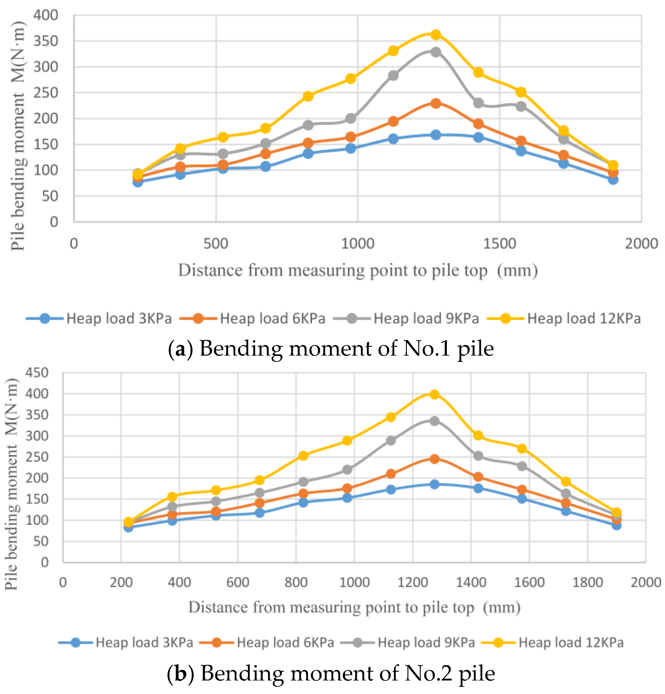
3.1. Bending Moment Analysis of Pile

In order to analyze the variation law of each measured bending moment value of the pile, the pile-bending moment distribution function M z was obtained by taking the magnitude of the heap load as an independent variable factor and fitting it with the Lorentz function.
In Figure 8, with the increase in the surcharge at the top of the slope, the bending moment at each point of the pile body shows an increasing trend, but the curve does not change greatly.
The bending moment of each point in pile No.1 is smaller than those in pile No.2 due to the fact that pile No.1 is located outside the row of piles and is weakly influenced by the soil-arching effect.
The bending moments at the top and bottom of the pile are small, the maximum bending moment of the pile body appears about 1250 mm from the top of the pile, and the peak bending moment of the pile body appears at basically the same point under all levels of surcharge. The test results are consistent with the calculation results obtained by our finite element calculation model.
Influenced by the boundary effect of the model, the pile diameter of the model pile is large and its bending stiffness is large; therefore, the bending moment of the pile is relatively small when the pile load is less than 6 KPa.
Following the change in the bending moment curve of the pile, a sudden change occurs about 2/3 from the top of the pile, leading to a strong growth trend.
The sudden change point should be the potential sliding surface position of the slope in the reinforced-fill area.

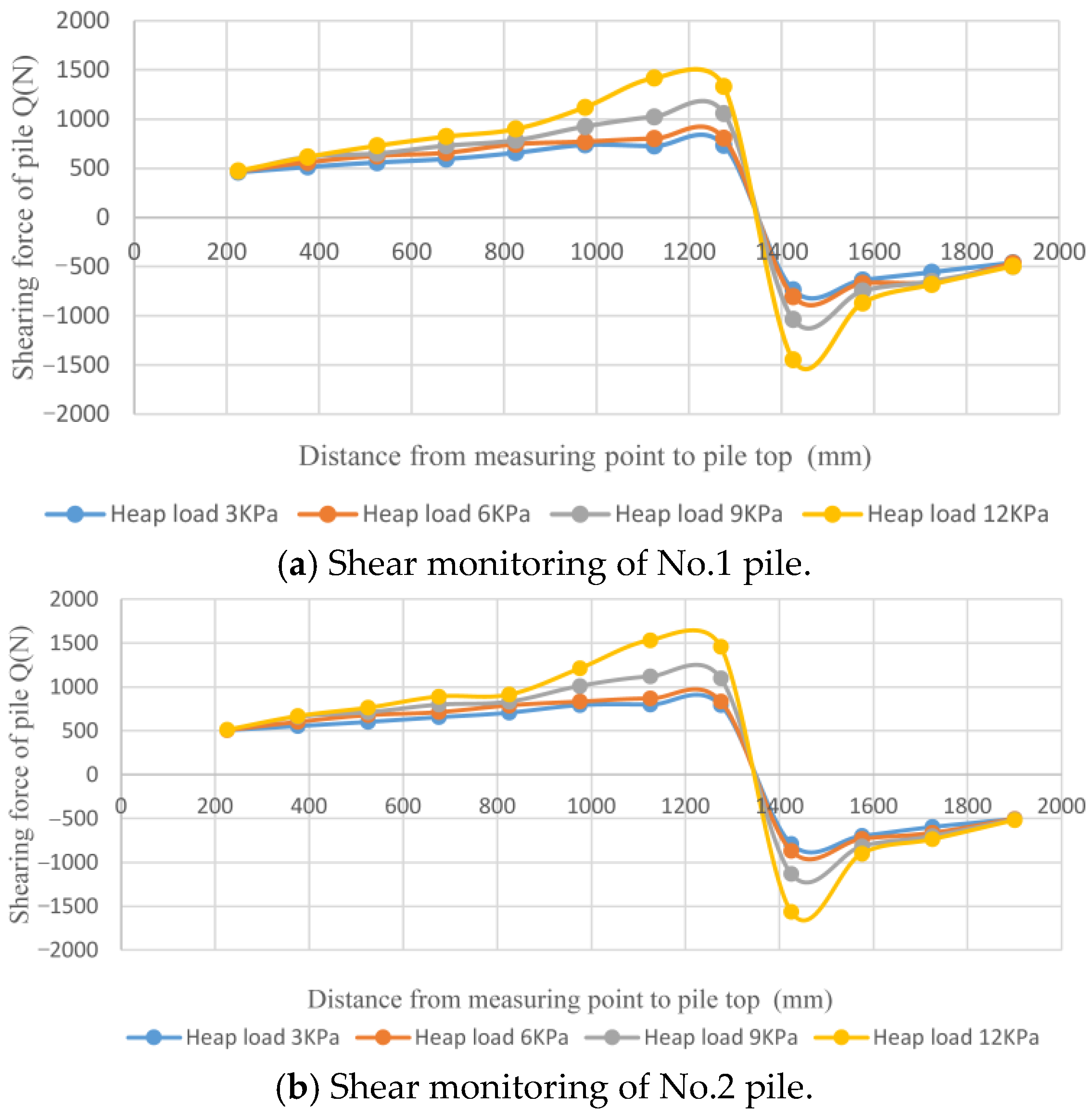
3.2. Shear Analysis of Pile

Based on the derivation of the bending moment equation of the pile, the shear distribution function Q z of the model pile can be obtained, which stipulates that the shear force of the pile is positive in the counterclockwise direction and negative in the clockwise direction [8].
Q z = M z = 16 A ω z z c 4 z z c 2 + ω 2 2
It can be seen from Figure 9 that the shear curves of the No.1 and No.2 piles are “S-shaped” under the four-stage surcharge. The shear curves of both piles undergo the process of sign transformation, which is similar to the change law of the bending moment curves of the piles.
The reason for the above results is that pile No.1 is located outside and its pile shear value is smaller than that of pile No.2.
In the pile bending moment shown in Figure 8, the maximum positive shear force also appeared at the maximum bending moment, which occurred on the potential sliding surface of the slope in the reinforced-fill area.
The shear force distribution of the pile below the potential sliding surface moves from positive to negative. Its absolute value gradually decreases and an extreme value appears about 1450 mm from the top of the pile.
The maximum normal shear force of the pile body is located about 150 mm below the embedding point.

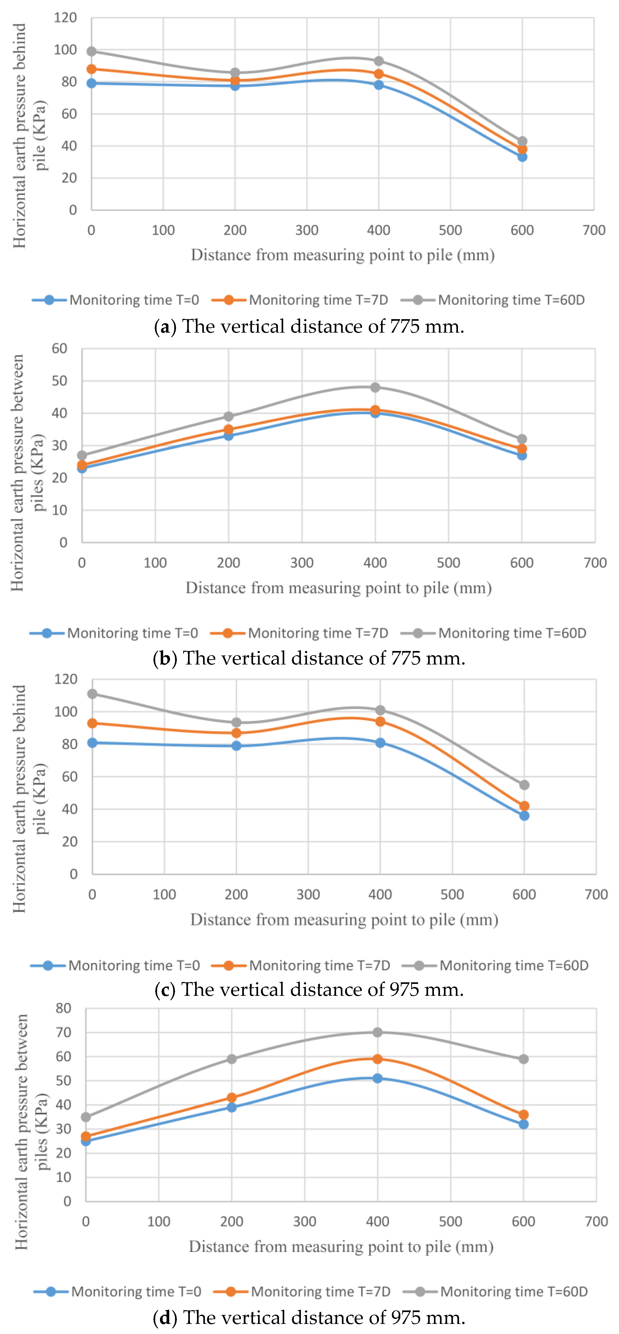
3.3. Analysis of Earth Pressure in Fill Area

During the test, we buried an earth pressure gauge in the reinforced-fill soil behind the pile and monitored the distribution of earth pressure on different sections behind the pile under the action of surcharge.
During analysis, we chose the loading condition of P = 12 KPa, took the duration after loading as the independent variable, and chose three time nodes, namely T = 0 (loading completed), T = 7 D, and T = 60 D, to read and measure the earth pressure.
According to the symmetry principle [9,10,11], the earth pressure behind piles 2 and 3 was analyzed.
In Figure 10, with the continuous increase in stacking time, the horizontal earth pressure behind piles and between piles shows an increasing trend.
In the same monitoring plane, the horizontal earth pressure at each point behind the piles is greater than that between the piles, which is mainly caused by the transfer of horizontal earth pressure to the arch foot (pile foundation) due to the soil arch effect.
The earth pressure behind the pile in the two monitoring planes showed a general downward trend, and increased slightly 400 mm from the pile because the arching effect gradually weakened with the increase in distance, while the horizontal force increased at the potential sliding surface of the slope at a distance of 400 mm.
The horizontal earth pressure between piles increased and then decreased on both monitoring surfaces, the peak value appeared in the distance range of 300 mm~500 mm behind the pile, and the peak value change in the lower monitoring surface was more obvious.
The above results are due to the increase in horizontal earth pressure caused by the surcharge in this layer and the more obvious soil-arching effect.

4. Mechanism Analysis of the Soil Arch Behind the Pile

Based on the relevant literature [12,13,14,15,16], the research results of relevant scholars, and our summary and analysis of the monitoring data derived from the test and field observations, we divided the formation and evolution of soil arch behind piles in the reinforced fill area into five stages:
(1)
Compressive stress concentration stage: At the initial stage of surcharge loading, the reinforced-fill slope tends to move forward under the action of the horizontal earth pressure caused by surcharge loading at the top of the slope, which has the effect of compacting the soil behind the pile and forming a compressive stress concentration area behind the pile.
(2)
Formation of a soil arch between piles: With the gradual increase in stacking load at the top of the slope and the increase in stacking time, the stress becomes more concentrated. As it is not retained, the soil between piles undergoes a certain horizontal displacement under the action of horizontal pressure, and a friction soil arch is formed between piles.
(3)
Formation of soil arch behind piles: With the continuous increase in horizontal earth pressure and the limited bearing capacity of the friction soil arch, the stress concentration area of the arch foot behind the pile further expands until an arch-bearing structure is formed behind the adjacent arch foot; that is, a direct soil arch is formed behind the pile.
(4)
Extrusion of soil arch between piles: Under the long-term effect of surcharge, the soil arch between piles and behind piles enters a stable development stage. Because of the weak bearing capacity of the soil arch between piles, with the further increase in stress, the soil between piles shows signs of spalling. After the friction arch foot is destroyed, the soil between piles is squeezed out and the soil arch effect between piles disappears.
(5)
Stable development of soil arch: After the collapse of the soil arch between piles, the soil arch behind the piles enters a stable development stage. If the surcharge on the top of the slope continues to increase, after the horizontal stress reaches the bearing capacity limit of the soil arch behind the pile, cracks occur behind the arch ring, and soil will flow around the pile body.

5. Conclusions

(1)
There is an obvious soil-arching effect in the slope behind the pile and the soil-arching effect is obviously enhanced by an increase in depth.
(2)
The soil arch formed in the reinforced-soil slope behind the model pile is composed of two parts, namely, the friction arch between the piles and the direct soil arch behind the pile. The spatial distribution of the two parts is different and there is a difference in normal stress. The direct soil arch behind the pile bears most of the horizontal stress, which plays a decisive role in the stability of the soil behind the pile and the stress of the pile.
(3)
The maximum bending moment of the pile body is basically consistent with the position of the potential sliding surface of the reinforced-fill slope, and should be calculated as the control point of the pile foundation design.

Author Contributions

Conceptualization, L.Z. and Q.W.; methodology, L.Z.; software, Q.W.; validation, L.Z., Q.W. and J.L.; formal analysis, L.Z.; investigation, Q.W.; resources, J.L.; data curation, L.Z.; writing—original draft preparation, L.Z.; writing—review and editing, Q.W.; visualization, J.L.; supervision, Q.W.; project administration, J.L.; funding acquisition, L.Z. All authors have read and agreed to the published version of the manuscript.

Funding

This research was funded by [The Science and Technology Research Program of Chongqing Municipal Education Commission] grant number [KJZD-K202305201] And [The Chongqing Transportation Science and Technology Project] grant number [CQJT-ZCXM2023-12] And [The Science and Technology Project of East China Survey and Design Institute of China Power Engineering Corporation] grant number [HDEC-KJ-2022-CQ01]. The funder was not involved in the study design, collection, analysis, interpretation of data, the writing of this article or the decision to submit it for publication.

Data Availability Statement

Data are contained within the article.

Conflicts of Interest

Author Liangdong Zuo was employed by the company Shanghai Jiao Tong University, China Railway Changjiang Transport Design Group Co., Ltd. and Chongqing College of Architecture and Technology. The remaining authors declare that the research was conducted in the absence of any commercial or financial relationships that could be construed as a potential conflict of interest.

References

  1. Kuang, L. Study on Soil Nailing Based on Soil Arching. Ph.D. Thesis, Central South University, Changsha, China, 2002. [Google Scholar]
  2. Chen, Z. Study on the Properties of Composite Foundation with Immersed Tube and Pile Under Embankment Load. Ph.D. Thesis, Zhejiang University, Hangzhou, China, 2005. [Google Scholar]
  3. Zhang, Z.-H.; Chen, Q.-N.; Wang, J.; Li, S. Method for determining spacing of supporting piles based on soil arching effect. J. Hunan Univ. Sci. Technol. (Nat. Sci. Ed.) 2010, 25, 72–75. [Google Scholar]
  4. Hui, W.; Wu, Y.; Zhao, Y. Reasonable pile spacing analysis of curtain piles based on soil arching effect. J. Yangtze River Sci. Res. Inst. 2015, 32, 67–71+86. [Google Scholar]
  5. Zheng, J.; Luo, X.; Fu, H.; Cao, W. Pile-supported reinforced embankment analysis based on H&R soil arch model. J. Huazhong Univ. Sci. Technol. (Nat. Sci. Ed.) 2019, 47, 50–54. [Google Scholar]
  6. Liu, H.; Han, Y.; Yang, J. Large deflection of curved elastic beams made of Ludwick type material. Appl. Math. Mech. (Engl. Ed.) 2017, 38, 909–920. [Google Scholar] [CrossRef]
  7. Qin, S.; Wang, Y.; Ren, L. Study on the essential attributes and fitting of a class of Lorentz curves. Math. Pract. Cogn. 2014, 44, 86–91. [Google Scholar]
  8. Zhao, M.; Peng, W.; Yang, C.; Xiao, Y. Finite difference decomposition of internal force calculation of double piles in high and steep cross slope section. China J. Highw. Transp. 2019, 32, 87–96. [Google Scholar]
  9. Zhao, M.; Peng, W.; Yang, C.; Xiao, Y. Study on the spacing of anti-slide piles considering the combined action of soil and arch behind piles. Highw. Traffic Sci. Technol. 2019, 36, 87–94+116. [Google Scholar]
  10. Jiang, T.; Lei, J.; Wang, R.; Zhang, J. Comparative model test study on reinforcement effect of anti-slide piles with different pile arrangement methods. J. Basic Sci. Eng. 2019, 27, 404–417. [Google Scholar]
  11. Ye, J.; Yu, J.; Lin, Z.; Zhou, X.Q.; Liu, S.Y.; Tu, B.X. Experimental study on horizontal push pile model of cantilever double-row anti-slide pile with variable stiffness. J. Civ. Eng. 2019, 52, 193–201. [Google Scholar]
  12. Chen, G.; Chen, Y.h.; Xu, K.; Qi, C.G.; Cai, R. Field test of soil arching effect of pile-supported reinforced embankment. J. Chang. Univ. (Nat. Sci. Ed.) 2016, 36, 41–47. [Google Scholar]
  13. Jin, L.; Hu, X.; Tan, F.; He, C.; Zhang, H.; Zhang, Y. Experimental study on soil arching effect of anti-slide pile based on infrared thermal imaging technology. Rock Soil Mech. 2016, 37, 2332–2340. [Google Scholar]
  14. Liang, Y.; Jiang, C.; Li, Q.; Li, F.; Zhao, X. Experimental study on soil arching effect and stress mechanism of composite structures between piles. J. Rock Mech. Eng. 2014, 33, 3825–3828. [Google Scholar]
  15. Chen, Q.; Guo, S.; Xu, C.; Liang, L.; Liu, X. Experimental study on the failure modes of loose earth pressure and displacement in loose zone in sandy soil. J. Cent. South Univ. (Nat. Sci. Ed.) 2019, 50, 108–117. [Google Scholar]
  16. Gu, H.; Luo, C. Model test on soil arching effect of foundation pit supported by sparse piles and soil nailing wall. J. Jilin Univ. (Eng. Ed.) 2018, 48, 1712–1724. [Google Scholar]
Figure 1. Model test design (unit: mm).
Symmetry 17 00188 g001
Figure 2. Test pool and model pile.
Symmetry 17 00188 g002
Figure 3. Strain gauge arrangement of the model pile.
Symmetry 17 00188 g003
Figure 4. Design and manufacturing of model ribbon.
Symmetry 17 00188 g004
Figure 5. Filling process of the reinforced soil model.
Symmetry 17 00188 g005
Figure 6. Loading and monitoring design.
Symmetry 17 00188 g006
Figure 7. Loading and monitoring process.
Symmetry 17 00188 g007
Figure 8. Monitoring results of the pile-bending moment.
Symmetry 17 00188 g008
Figure 9. Monitoring results of pile shearing force.
Symmetry 17 00188 g009
Figure 10. Distribution of earth pressure behind piles.
Symmetry 17 00188 g010
Table 1. Model pile size parameters.
Serial NumberParameterPrototypeCalculation ParameterModel Parameter
1Pile length (mm)3800019001900
2Pile diameter (mm)2500125125
3Pile spacing (mm)8000400400
4Rock-embedded depth (mm)>5 D625625
Disclaimer/Publisher’s Note: The statements, opinions and data contained in all publications are solely those of the individual author(s) and contributor(s) and not of MDPI and/or the editor(s). MDPI and/or the editor(s) disclaim responsibility for any injury to people or property resulting from any ideas, methods, instructions or products referred to in the content.

