Article

Symmetry-Inspired Design and Full-Coverage Path Planning for a Multi-Arm NDT Robot on a Reactor Pressure Vessel

1
School of Electronic Science & Engineering, Southeast University, Nanjing 210096, China
2
CGN Inspection Technology Co., Ltd., Suzhou 215021, China
3
School of Mechanical Engineering, Hebei University of Technology, Tianjin 300401, China
4
School of Material Science & Engineering, Southeast University, Nanjing 210096, China
*
Authors to whom correspondence should be addressed.
Symmetry 2025, 17(11), 1995; https://doi.org/10.3390/sym17111995
Submission received: 27 September 2025 / Revised: 5 November 2025 / Accepted: 10 November 2025 / Published: 18 November 2025
(This article belongs to the Section Engineering and Materials)

Abstract

Regular ultrasonic full-coverage inspection of reactor pressure vessels (RPVs) is critical to ensuring the safe operation of nuclear power plants. However, due to the extreme operating conditions and complex internal geometry of RPVs, most existing inspection technologies face significant challenges in achieving convenient and efficient full-coverage traversal detection. To address these limitations, this study proposes a novel nondestructive inspection robot equipped with four symmetrically arranged inspection arms for comprehensive RPV ultrasonic inspection. By considering the structural symmetry and motion characteristics of the inspection arms, a corresponding kinematic analysis is conducted, resulting in a precise kinematic model that enables real-time computation of both forward and inverse kinematic solutions with high accuracy. Furthermore, an adaptive full-coverage inspection method is developed by leveraging the vessel’s axisymmetric geometry and by partitioning the RPV into seven distinct detection zones, allowing the four inspection arms to independently complete inspections across the maximum number of zones, thereby significantly enhancing both detection coverage and operational efficiency. Experiments demonstrated the practical feasibility of the proposed robotic system and validated the effectiveness of the full-coverage inspection method.

1. Introduction

Nuclear energy, due to the growing global energy demand, has regained the role it played in the 20th century as an alternative to CO2-emitting electric power generation technologies [1]. Safe operation has always been the cornerstone of nuclear energy development, where structural symmetry plays a vital role in maintaining system integrity. Nondestructive testing (NDT), as a critical component of the safe operation of nuclear power plants (NPPs), has consistently been a prominent area of research worldwide [2]. The RPV, characterized by its axisymmetric geometry, is a key pressure-bearing component in NPPs [3,4], and is subjected to extreme operational conditions—including prolonged high temperatures, high pressures, and intense neutron irradiation—throughout its service life [5]. Damage to the RPV can lead to catastrophic radioactive leaks. Studies confirm that crack propagation within the RPV under long-term irradiation embrittlement is a primary failure mechanism [6]. Consequently, the International Electrotechnical Commission (IEC) mandates early defect identification through full-coverage nondestructive testing (NDT), especially with volume inspection methods such as ultrasonic testing (UT), as codified in the ASME Boiler and Pressure Vessel Code, Section XI [7].
Traditional inspection of RPVs primarily relies on manual visual examination and basic techniques such as liquid penetrant testing (PT), which are predominantly effective for inspecting surface cracks and macroscopic defects. These methods require operators to work in close proximity to high-radiation zones and struggle to inspect concealed areas, such as nozzle intersection regions. To address these limitations, Ducros et al. [8] developed the RICA robot, featuring a tracked locomotion mechanism for semi-automated inspections. However, its inability to adapt to multi-curvature surfaces limits deployment in confined spaces. Kim et al. [9] introduced a laser-guided mobile robot for weld inspection in reactor nozzle regions. Hong et al. [10] developed an 11-degree-of-freedom (DOF) nondestructive inspection robotic system with a radially symmetric architecture. Through innovative mechanical design and kinematic analysis, this system achieves efficient full-surface inspection of RPVs.
In the nondestructive testing of pressure vessels, the motion control accuracy and reliability of robotic arms directly affect the precision of inspection results. Currently, the Denavit–Hartenberg (D-H) model [11,12,13] is predominantly used for robotic arm kinematic modeling, with researchers continually refining it to improve accuracy. For instance, the team led by Shin Hocheol employed an improved D-H model to achieve precise robotic positioning for inspecting steam generator tubes in nuclear power plants, addressing specific requirements in this context [14]. Additionally, modeling methods such as the quaternion approach [15] and the product of exponentials (POE) method [16] have gradually gained traction in this field. To solve inverse kinematics, existing approaches mainly include analytical methods [17,18], numerical methods [19,20,21], and intelligent algorithms [22,23]. Among these, intelligent algorithms have emerged as a research hotspot due to their global optimization capability, strong robustness, and independence from precise modeling. For example, Hassan Ahmed et al. adopted a recurrent neural network architecture to overcome issues such as modeling errors and insufficient singularity avoidance encountered with analytical and numerical methods in solving inverse kinematics [24]. However, in pressure vessel inspections, single-arm robots are constrained by their workspace and degrees of freedom, leading to cumulative end-effector positioning deviations in complex areas such as head and nozzle welds. This makes it challenging to meet the stringent requirements of submillimeter-level inspection accuracy.
Full-coverage path planning is a critical technology for ensuring that inspection equipment systematically scans all detectable areas of pressure vessels while simultaneously meeting multiple requirements, including detection accuracy, safety during obstacle avoidance, and motion efficiency. Due to the complex geometric features of pressure vessels—such as cylindrical bodies, curved heads, and nozzle welds—as well as common challenges in inspection environments, such as confined spaces and interference with obstacles, traditional random-path approaches struggle to achieve conformal coverage, significantly increasing the complexity of UT [25]. In recent years, researchers have proposed various optimization strategies for different geometric characteristics, including spiral scanning, layered zoning, and fractal adaptive methods, combined with intelligent optimization algorithms to enhance path robustness [26]. However, critical areas such as complex curved surfaces and weld-dense regions still suffer from inspection blind spots or repeated scanning, directly impacting detection efficiency and defect detection rates. Therefore, there is an urgent need to develop high-coverage, high-precision intelligent path planning methods that integrate the geometric features and operational conditions of pressure vessels.
To address these challenges, this study proposes a quadruple-robotic-arm cooperative NDT system with three innovative features:
(1)
Symmetrical Deployment for Enhanced Coverage: A four-arm, radially symmetric configuration with redundant degrees of freedom (DOF) and modular joint design achieves full-pose coverage in complex geometries, improving inspection efficiency by 40–60% over single-arm systems.
(2)
Comprehensive Kinematics Analysis: An improved Denavit–Hartenberg (D-H) parameter model coupled with multi-arm collaborative control enables submillimeter-level positioning accuracy, effectively mitigating kinematic singularities inherent in single-arm systems.
(3)
Hierarchical Zonal Algorithm: Geometric feature-based partitioning divides the inspection area into seven sub-regions—including circumferential weld zones, flange regions, and nozzle-to-shell and nozzle-to-safe end areas. The simulation results demonstrate that the proposed full-coverage traversal inspection method effectively improves the detection coverage rate.
This paper is organized into four sections. Section 1 elaborates on the structural characteristics of the RPV and the NDT robot design. Section 2 establishes the kinematic model of the inspection arms and resolves forward/inverse kinematic solutions. Section 3 proposes an adaptive full-coverage traversal detection method based on zonal partitioning. Section 4 validates the robotic system’s performance and the effectiveness of the detection method through simulation experiments.

2. Design of NDT Robot

2.1. Introduction to Robot’s Working Environment

As shown in Figure 1a, the RPV consists of four significant components: flange, nozzles, shells, and lower head. To ensure the smooth operation of the RPV, components are welded together to make the RPV gapless. Compared with the high-strength components, the welds between the components are the most vulnerable part of the whole RPV, and damage can cause radioactive pollutants to leak. So, NDT of welds is the focus of research in RPV inspection.
According to the inspection requirements of ASME code section XI, the inspection targets for RPV include all shell welds, the inner radius of nozzles, and the cladding layer. Except for the cladding layer on the inner surface, which is inspected by video, the remaining areas need to be inspected by UT. As shown in Figure 1b, the UT area includes the circumferential weld of the shell, lower head weld, active core region, nozzle-to-shell weld (shell side and nozzle bore side), nozzle-to-safe end weld, outlet nozzle inner radius, and inlet nozzle inner radius.

2.2. Introduction to Nondestructive Inspection Robot

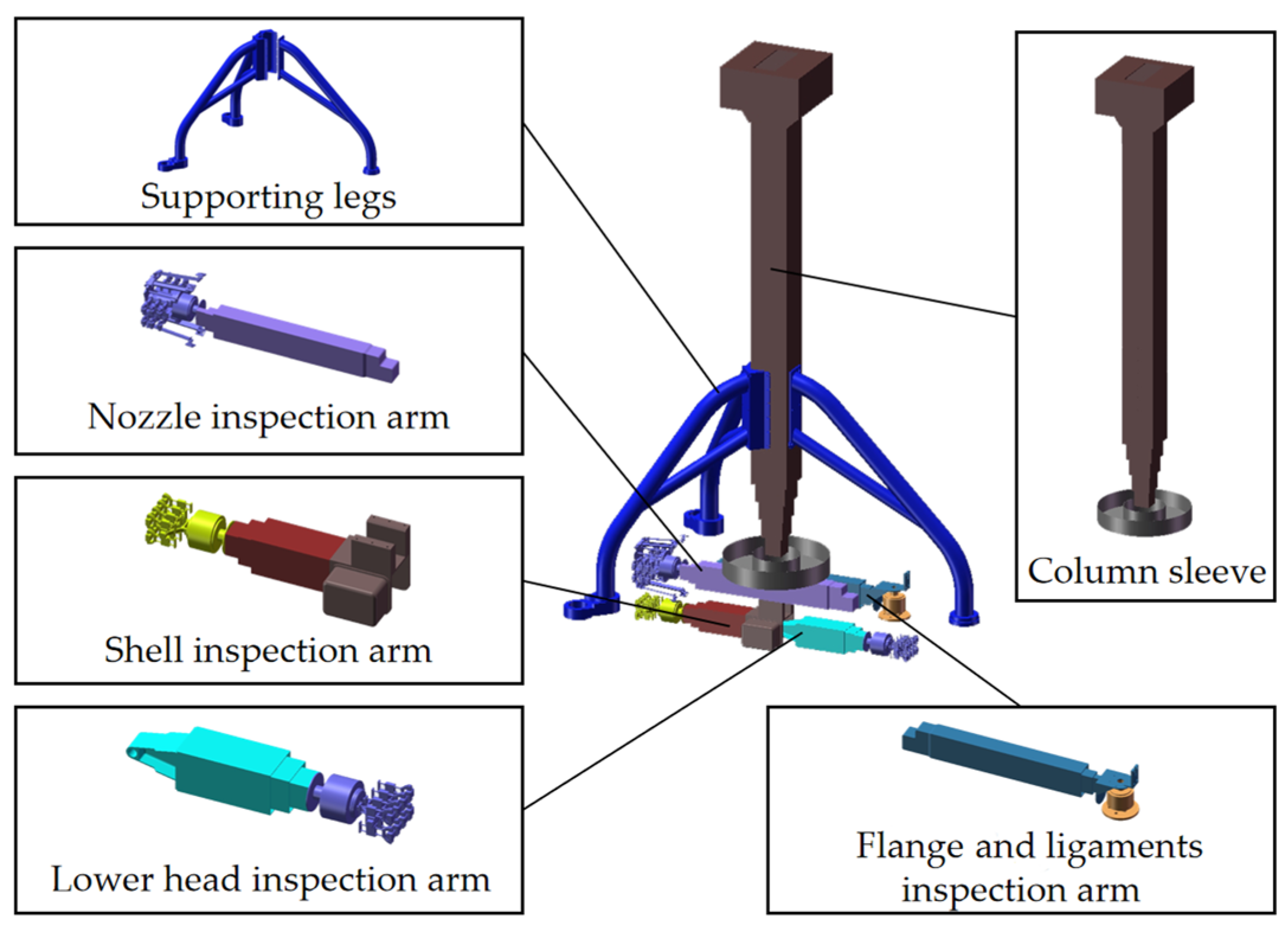
In this study, we design an NDT robot with 11 degrees of freedom. This robot features a central column sleeve and a main rotating assembly, from which four inspection arms are deployed in a radially symmetrical layout around the vessel’s central axis, comprising the nozzle, flange/ligaments, shell, and lower head inspection arms. Its maximum axial reach is 11.2 m. It is capable of inspecting RPVs with diameters ranging from Φ 3.4 m to Φ 4.8 m. The structure is shown in Figure 2.
The column sleeve serves as the structural support for the NDT robot, enabling the inspection arms to move along the RPV’s axis. The main rotating assembly is connected to the lower part of the column sleeve. It can provide rotation around the RPV’s axis for all inspection arms. The supporting legs are installed in the middle of the outermost column of the column sleeve, providing stable support for the robot. The flange and ligaments inspection arm, nozzle inspection arm, shell inspection arm, and lower head weld inspection arm are installed at the bottom of the circumferential revolute pair below the main rotating assembly. Each of the four inspection arms has its own responsibilities for inspecting different areas of the RPV, respectively.
As shown in Figure 3, the shell inspection arm has one prismatic pair and one revolute pair. Its function is to inspect the shell welds and the active core region. The prismatic pair employs a ball screw that connects to the cable-driven mechanism, enabling telescopically nested, constant-velocity, and equidistant extension/retraction of hard aluminum alloy square tubes through a synchronized multi-stage actuation mechanism. The revolute pair is located at the connection between the prismatic pair and the shell inspection probe holder, enabling the shell inspection probe holder to change direction twice to achieve circumferential inspection.
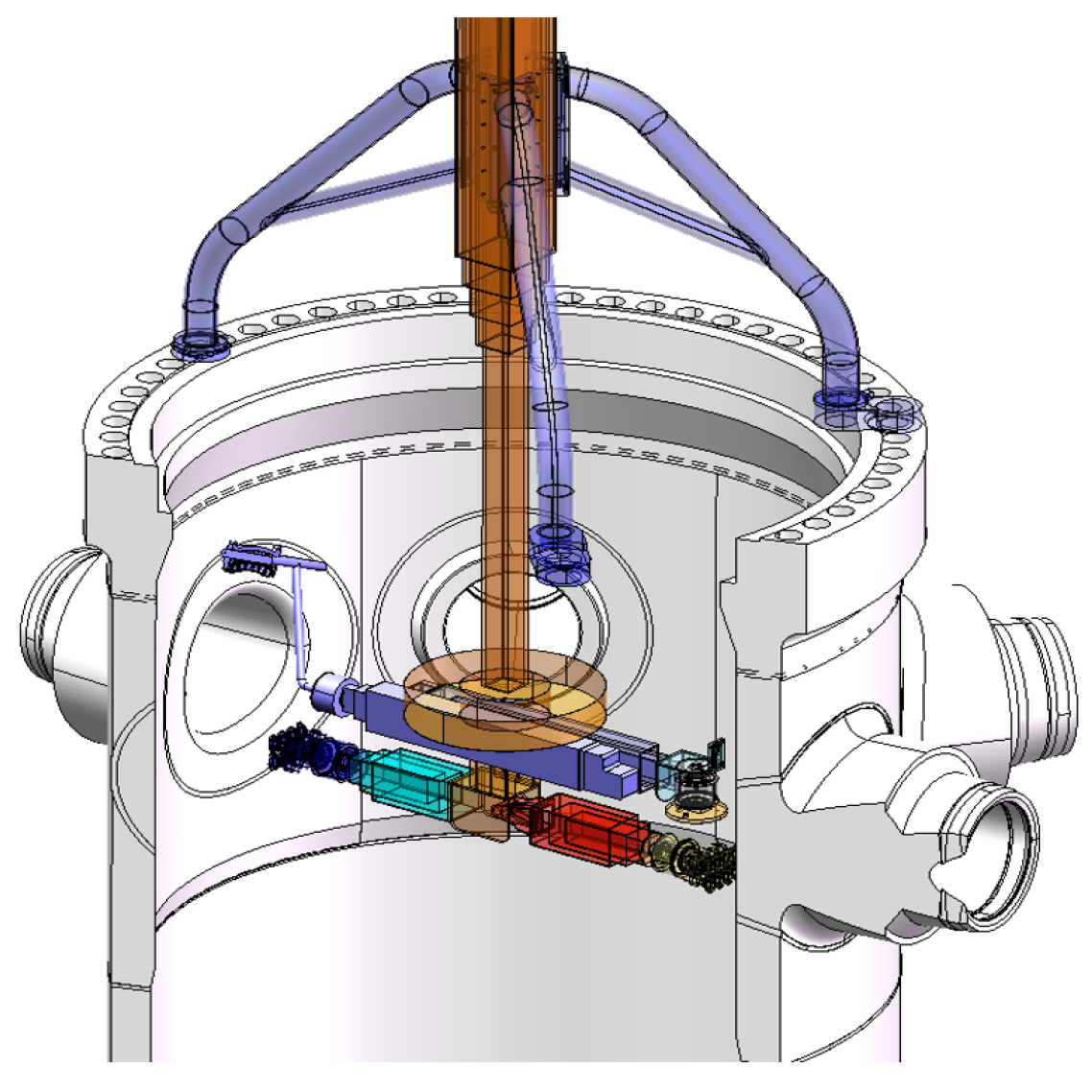
As shown in Figure 4, the nozzle inspection arm has one prismatic pair and one revolute pair, the same as the flange inspection arm. Its function is to inspect the nozzle-to-shell welds (nozzle bore side), nozzle-to-shell welds (shell side), nozzle-to-safe end welds, outlet nozzle inner radius, and inlet nozzle inner radius. The prismatic pair uses the same structure to achieve constant velocity and equidistant extension/retraction. The revolute pair is located at the connection between the prismatic pair and the nozzle-to-shell inspection probe holder, enabling the end-effectors to perform circumferential inspection inside the nozzles.
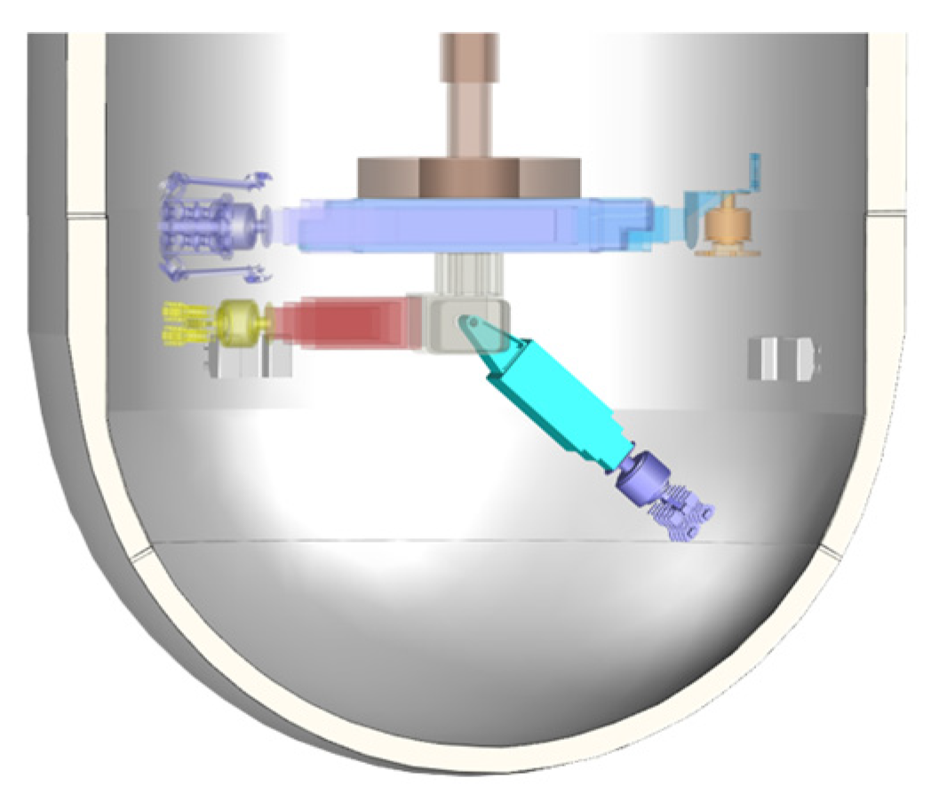
As shown in Figure 5, the lower head inspection arm has one prismatic pair and two revolute pairs. It is based on the shell inspection arm, with an additional revolute pair added at the base. This revolutionary pair combines a chain transmission with a two-stage worm gear transmission that features reverse self-locking. Simultaneously, it can cause the shell inspection arm to change from a horizontal to a vertical state, thereby enabling inspection of the lower head weld.

2.3. Control System Architecture

To ensure operational reliability for full-coverage nondestructive testing (NDT) in high-radiation environments, the robot incorporates a distributed hierarchical control architecture. The central computing unit, an Industrial Personal Computer (IPC), is responsible for high-level functionalities, including path planning, coordinate transformation, and task management. To mitigate the impact of radiation on sensitive electronic components, the IPC is positioned outside the radiation zone and connected to the robotic platform via extended cables. This remote configuration eliminates the need for bulky, complex radiation shielding for the central computing unit, thereby enhancing overall system reliability and safety. Real-time control of the robotic arms and acquisition of NDT sensor data are handled by ruggedized Programmable Logic Controllers (PLCs) mounted on the robot’s main body. A deterministic RS-485 communication protocol ensures robust data exchange between the external IPC and the embedded PLCs. This overall control system architecture is depicted in Figure 6.

3. Kinematic Analysis of the Inspection Arm

Based on the configuration characteristics of inspection arms in NDT robots, all inspection arms can be classified into two types. The Type I inspection arm encompasses the inspection arm for the flange holes, the ligament inspection arm, the nozzle inspection arm, and the shell inspection arm. Each of these inspection arms has four degrees of freedom and shares the same structure. The Type II inspection arm comprises the lower-head inspection arm, which has five degrees of freedom.
For each type, a kinematic analysis is systematically performed: based on the angles or lengths of each joint, the forward kinematics is used to obtain the position of the inspection arm’s end-effector. The purpose of the forward kinematics analysis is to compute transformation matrices between adjacent links by establishing joint coordinate systems. The complete forward kinematics equation for the manipulator is then derived via cascading multiplication of these individual transformation matrices. For inverse kinematics, leveraging the specific structural characteristics of each inspection arm type, given the desired end-effector posture matrix, the joint angles and lengths are solved by combining the Denavit–Hartenberg (D-H) analytical method and the geometric method.

3.1. The Type I Inspection Arm

(1)
Forward Kinematics Modeling
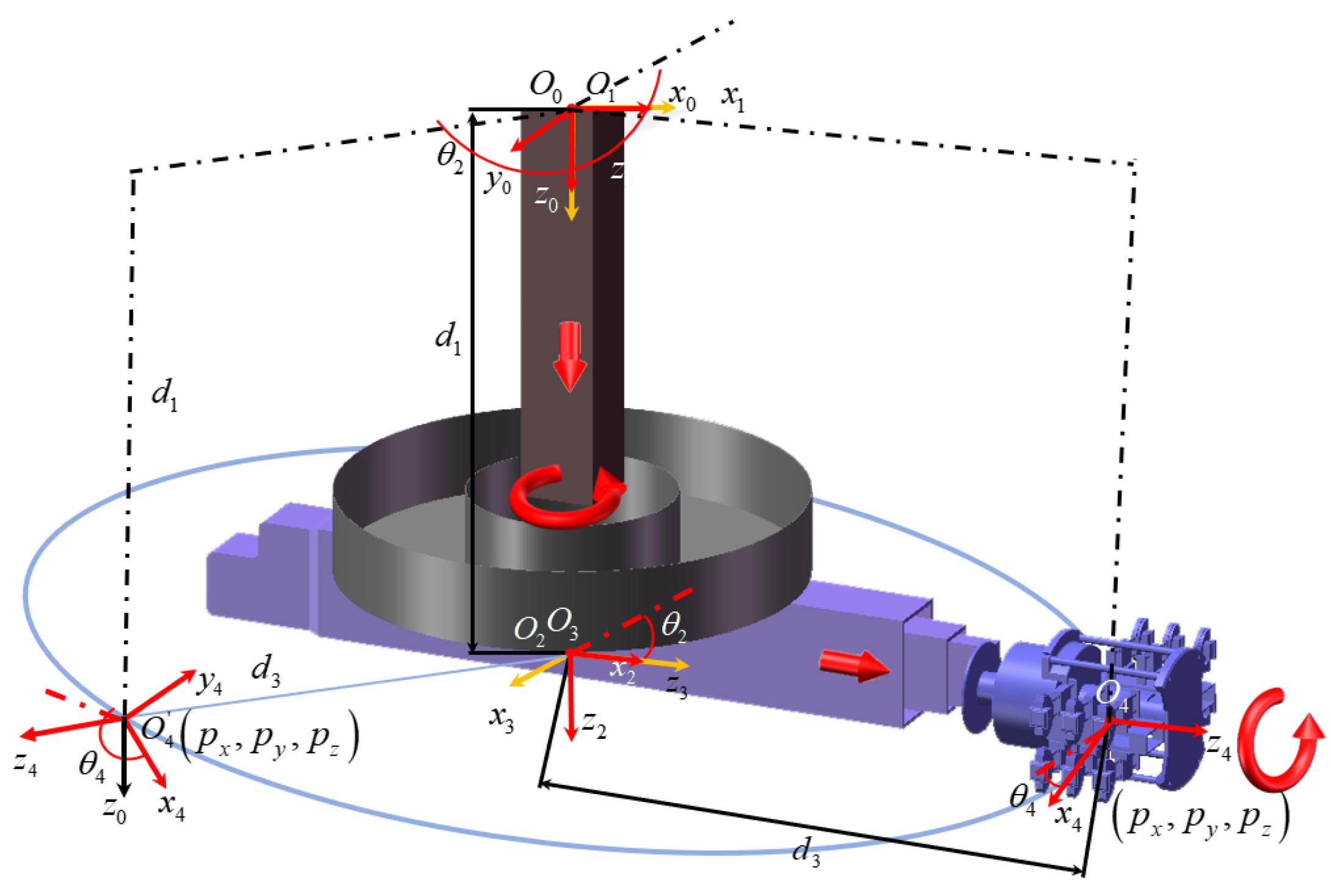
The Type I inspection arm has four joints: Prismatic Joint 1, Revolute Joint 2, Prismatic Joint 3, and Revolute Joint 4. Under the D-H convention, a base coordinate system is first established at the initial position of the Prismatic joints 1, and its origin is at O 0 . Joint coordinate systems are then defined, and their origins are located at points O 1 , O 2 , O 3 and O 4 , respectively. All coordinate systems adhere to the right-hand rule with symmetric orientation properties, as depicted in Figure 7. In Figure 7, d 1 and d 3 represent the prismatic lengths of Prismatic joints 1 and 3, and their value ranges are L 1 min , L 1 max and L 3 min , L 3 max , respectively. θ 2 and θ 4 represent the rotation angles of Revolute Joints 2 and 4 from their initial positions, whose angles are constrained within the range of π , π . By analyzing the established coordinate system, the D-H parameter table of the type-I maintenance manipulator can be obtained as shown in Table 1, where a n is the link length, α n is the twist angle, d n is the offset, and θ n is the joint angle.
Forward kinematics for the inspection arm refers to calculating the posture of the end-effector frame O n relative to the base frame O 0 using structural parameters and joint rotation angles. The posture matrix includes a position matrix and an orientation matrix of the end-effector frame origin in the base coordinate system, which is typically represented by a homogeneous transformation matrix T n 0 . The general form of the homogeneous transformation matrix is T n m = R n m P 0 1 , which describes the posture of frame n with respect to frame m . P = p x   p y   p z   Τ represents the positional offset, and R n m = n x o x a x n y o y a y n z o z a z is the rotation matrix defining orientation.
In the standard D-H method, the homogeneous transformation matrix of link n and respect to link n 1 is shown in Equation (1).
T n n 1 = c θ n s θ n c α n s θ n s α n a n c θ n s θ n c θ n c α n c θ n s α n a n s θ n 0 s α n c α n d n 0 0 0 1
where s θ n denotes sin θ n , c θ n c α n denotes cos θ n cos α n , and other subsequent terms follow analogous notational contraction.
The transformation matrices T 1 0 , T 2 1 , T 3 2 , and T 4 3 for adjacent inspection arms can be obtained by substituting the data from Table 1 into Equation (1):
T 1 0 = 1 0 0 0 0 1 0 0 0 0 1 d 1 0 0 0 1 , T 2 1 = c 2 0 s 2 0 s 2 0 c 2 0 0 1 1 0 0 0 0 1 , T 3 2 = 1 0 0 0 0 1 0 0 0 0 1 d 3 0 0 0 1 , T 4 3 = c 4 s 4 0 0 s 4 c 4 0 0 0 0 1 0 0 0 0 1
where s 2 denotes sin θ 2 , and other subsequent terms follow analogous notational contraction.
The kinematics model of the Type I inspection arm is obtained by multiplying the transformation matrices of each adjacent joint in the above equation:
T 4 0 = T 1 0 T 2 1 T 3 2 T 4 3 = n x o x a x p x n y o y a y p y n z o z a z p z 0 0 0 1 = c 2 c 4 c 2 s 4 s 2 d 3 s 2 c 4 s 2 s 2 s 4 c 2 d 3 c 2 s 4 c 4 0 d 1 0 0 0 1
where c 2 c 4 denotes cos θ 2 cos θ 4 , s 2 s 4 denotes sin θ 2 sin θ 4 , and other subsequent terms follow analogous notational contraction.
The T 4 0 matrix represents the posture of the end-effector frame O 4 relative to the base frame O 0 for the Type I inspection arm, which includes both the position matrix P and the rotation matrix R 4 0 .
(2)
Inverse Kinematics Modeling
The inverse kinematics solution for the Type I inspection arm determines the joint variables d 1 , θ 2 , d 3 , and θ 4 from a given end-effector posture matrix T 4 0 . The parameters of each joint can be determined by analyzing the inspection arm’s kinematic configuration and exploiting its geometric constraints and relationships among joints. Analysis of the terminal joint reveals that the end-effector’s motion traces a circular trajectory within a plane parallel to the plane x 0 O 0 y 0 . The center point of the trajectory is at point O 3 , and the radius is d 3 , as shown in Figure 8. The height d 1 of the plane where the trajectory circle lies can be obtained from the p z component in the position matrix P :
d 1 = p z
The position of the end of the robotic arm in the base coordinate system is p x , p y , p z , and it is on a circular trajectory with a radius of d 3 . The value of d 3 can be obtained using the Pythagorean theorem:
d 3 = p x 2 + p y 2
Within the trajectory plane at the end of the inspection arm, the value of θ 2 can be obtained by applying inverse trigonometric functions to the end position:
θ 2 = π arctan p x / p y p x > 0 , p y > 0 arctan p x / p y + π / 2   p x > 0 , p y > 0 π arctan p x / p y   p x < 0 , p y > 0 arctan p x / p y π / 2   p x < 0 , p y < 0 0     p x = 0 , p y = 1 π / 2     p x = 1 , p y = 0 π   p x = 0 , p y = 1 π / 2       p x = 1 , p y = 0
Within the x 4 O 4 y 4 plane, the projection length of vector x 4 onto the z 0 -axis is x 4 sin θ 4 , which equals n z in the posture matrix T 4 0 . While the projection length of vector y 4 onto the z 0 -axis is y 4 cos θ 4 , which equals o z in the same posture matrix. The vectors x 4 , y 4 , and z 0 are all unit vectors, and their magnitudes are all equal to 1.
By combining the projection formulas of x 4 and y 4 on z 0 , the value of the angle θ 4 can be obtained as
θ 4 = arctan n z / o z + π n z > 0 , o z < 0 arctan n z / o z       n z > 0 , o z > 0 arctan n z / o z       n z < 0 , o z > 0 arctan n z / o z π n z < 0 , o z < 0 0     n z = 0 , o z = 1 π / 2     n z = 1 , o z = 0 π             n z = 0 , o z = 1 π / 2       n z = 1 , o z = 0

3.2. The Type II Inspection Arm

(1)
Forward Kinematics Modeling
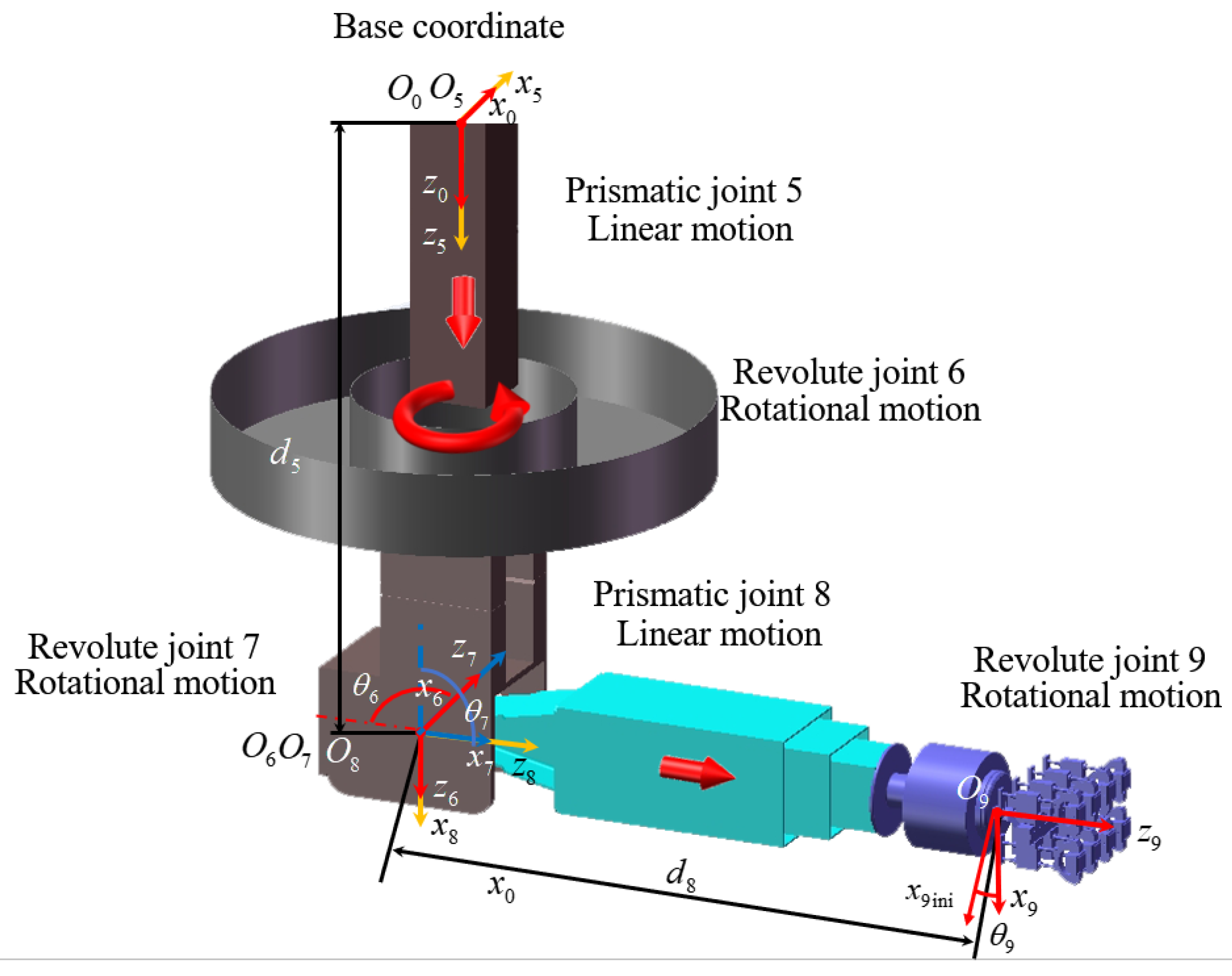
The Type II inspection arm contains five joints, namely, Prismatic Joint 5, Revolute Joint 6, Revolute Joint 7, Prismatic Joint 8, and Revolute Joint 9. Under the D-H convention, a base coordinate system is first established at the initial position of Prismatic Joint 5, which is similar to Prismatic Joint 1 in the Type I inspection arm, and its origin is at O 0 .
Under the D-H rule, the base coordinate system is first established, and its origin is at point O 0 . Coordinate systems are then defined for each joint, with their origins located at points O 5 , O 6 , O 7 , O 8 , and O 9 , respectively. All coordinate systems adhere to the right-hand rule and orientations, as depicted in Figure 9. In Figure 9, d 5 and d 8 represent the prismatic lengths of Prismatic Joints 5 and 8, and their value ranges are L 5 min , L 5 max and L 8 min , L 8 max , respectively. θ 6 , θ 7 , and θ 9 represent the rotation angles of Revolute Joints 6, 7, and 9 from their initial positions. The posture in Figure 9, x 9 , coincides with its initial position x 9 ini . To represent θ 9 clearly, x 9 ini is offset by a small angle in Figure 9. The value range of θ 7 is π / 2 , π , and the value ranges of both θ 6 and θ 9 are π , π . Through the analysis of the established coordinate system, the D-H parameter table of the Type II inspection arm can be obtained as shown in Table 2, where a n is the link length, α n is the twist angle, d n is the offset, and θ n is the joint angle.
The transformation matrices T 5 0 , T 6 5 , T 7 6 , T 8 7 , and T 9 8 for adjacent inspection arms can be obtained by substituting the data from Table 2 into Equation (1):
T 5 0 = 1 0 0 0 0 1 0 0 0 0 1 d 5 0 0 0 1 , T 6 5 = c 6 0 s 6 0 s 6 0 c 6 0 0 1 0 0 0 0 0 1 , T 7 6 = c 6 0 s 7 0 s 6 0 c 7 0 0 1 0 0 0 0 0 1 T 8 7 = 1 0 0 0 0 1 0 0 0 0 1 d 8 0 0 0 1 , T 9 8 = c 9 s 9 0 0 s 9 c 9 0 0 0 0 1 0 0 0 0 1
The kinematics model of the Type II inspection arm is obtained by multiplying the transformation matrices of each adjacent joint in the above equation:
T 9 0 = T 5 0 T 6 5 T 7 6 T 8 7 T 9 8 = n x o x a x p x n y o y a y p y n z o z a z p z 0 0 0 1 = s 6 s 9 + c 6 c 7 c 9 c 9 s 6 c 6 c 7 s 9 c 6 c 7 d 8 c 6 s 7 c 6 c 9 s 6 c 6 s 9 c 6 s 9 c 7 s 6 s 9 s 6 c 7 d 8 s 6 s 7 c 9 s 7 s 7 s 9 c 7 d 5 d 8 c 7 0 0 0 1
where s 6 s 9 + c 6 c 7 c 9 denotes sin θ 6 sin θ 9 + cos θ 6 cos θ 7 cos θ 9 , and other subsequent terms follow analogous notational contraction.
The T 9 0 matrix represents the posture of the end-effector frame O 9 relative to the base frame O 0 for the Type II inspection arm, which includes both the position matrix P and the rotation matrix R 9 0 .
(2)
Inverse Kinematics Modeling
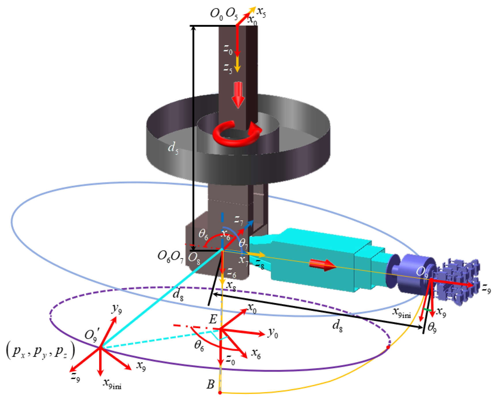
The inverse kinematics solution for the Type II inspection arm determines the joint variables d 5 , θ 6 , θ 7 , d 8 , and θ 9 from a given end-effector posture matrix T 9 0 . By analyzing the inspection arm’s structure and joint rotation angles, it was determined that the end-effector’s motion is constrained within a hemispherical space centered at point O 8 with radius d 8 , where the coordinates of the center O 8 is 0 , 0 , d 5 . When all other joints are fixed and only θ 7 is varied, the end-effector moves along the orange quarter-circular plane shown in Figure 10, where point B represents the intersection between the z 0 -axis and the quarter-circular trajectory. The projection length of vector z 9 onto the z 0 -axis is z 9 cos θ 7 , which equals the a z component in the same posture matrix. The value of angle θ 7 can be calculated using inverse trigonometric functions:
θ 7 = arccos a z
The rotation angle of the orange quarter-circular plane depends solely on angle θ 6 . When all other joint parameters are fixed and only angle θ 6 changes, the end-effector traces a circular trajectory in a plane, whose center always lies on the z 0 -axis. As shown in Figure 10, the center of this circular trajectory is denoted as point E . The trajectory circle lies in a plane parallel to the plane x 0 O 0 y 0 , denoted as x 0 E y 0 . Point O 9 represents an arbitrary point on the trajectory circle with coordinates p x , p y , p z . When the end-effector moves to point O 9 , its projection onto the plane x 0 E y 0 yields vector E O 9 . By analyzing the position of vector E O 9 within the plane x 0 E y 0 , angle θ 6 can be determined as
θ 6 = arctan p x / p y     p x > 0 , p y > 0 arctan p x / p y     p x > 0 , p y < 0 arctan p x / p y + π         p x < 0 , p y > 0 arctan p x / p y π         p x < 0 , p y < 0 0   p x = 1 , p y = 0 π / 2   p x = 0 , p y = 1 π           p x = 1 , p y = 0 π / 2     p x = 0 , p y = 1
The magnitude of vector E O 9 is d 8 sin θ 7 . In the plane x 0 E y 0 , the projection length of E O 9 on the x 0 -axis equals E O 9 cos θ 6 . The projection length of E O 9 on the y 0 -axis equals E O 9 sin θ 6 , which corresponds to the end-effector’s y 0 -axis coordinate. The position matrix P represents the end-effector’s coordinates, and based on these projection relationships, the following equations can be established:
p x = d 8 sin θ 7 cos θ 6 p y = d 8 sin θ 7 sin θ 6
The value of d 8 can be calculated as
d 8 = p x 2 + p y 2 sin 2 θ 7
The length of the end-effector in the z 0 -axis is p z in the position matrix P . According to the geometric relationship, d 5 , it can be determined that
d 5 = p z + d 8 cos θ 7
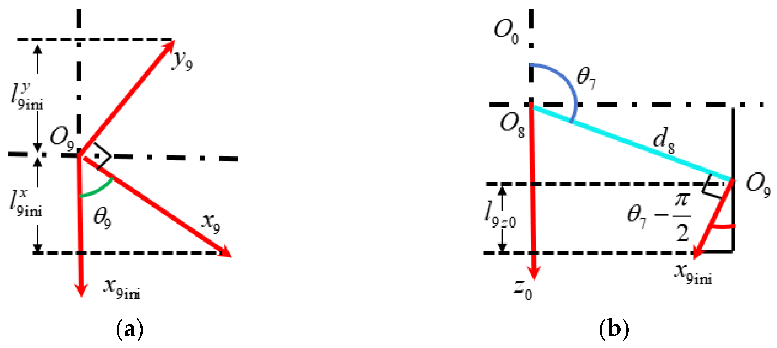
In the end-effector coordinate frame’s plane x 9 O 9 y 9 , as shown in Figure 11a, the projection length l 9 i n i x of vector x 9 onto the x 9 ini -axis equals x 9 cos θ 9 , while the projection length l 9 i n i y of vector y 9 onto the x 9 ini -axis equals y 9 sin θ 9 . In the plane O 0 O 8 O 9 , as shown in Figure 11b, the projection length l 9 z 0 of vector x 9 ini onto the z 0 -axis is given by x 9 ini sin θ 7 .
Using a two-step projection method, where the x 9 - and y 9 -axes are first projected onto the x 9 ini -axis and then onto the z 0 -axis, the resultant projection of x 9 -axis along the z0-axis is determined as x 9 sin θ 7 cos θ 9 , which corresponds to the n z component in the posture matrix T 9 0 , while the projection of the vector y 9 -axis along the z0-axis is y 9 sin θ 7 sin θ 9 , equaling o z in posture matrix T 9 0 . The vectors x 9 , y 9 , x 9 ini , and z 0 are all unit vectors, and their magnitudes are all equal to 1.
By applying inverse trigonometric functions to these geometric relationships, the rotation angle θ 9 can be derived as
θ 9 = arctan o z / n z     n z > 0 , o z < 0 π arctan o z / n z       n z < 0 , o z < 0 π arctan o z / n z           n z < 0 , o z > 0 arctan o z / n z     n z > 0 , o z > 0 0                   n z = 1 , o z = 0 π / 2         n z = 0 , o z = 1 π       n z = 1 , o z = 0 π / 2           n z = 0 , o z = 1

4. Adaptive Exhaustive Inspection

Following clarification of the kinematic principles of the NDT robotic system for RPV, it is imperative to establish a wall inspection path-planning method to enable automated robotic inspection. To achieve optimal detection efficiency, the method requires the categorical processing of RPV regions under inspection by integrating robotic structural characteristics with the ultrasonic probe specifications. Region-specific optimal inspection schemes are designed in accordance with the geometric and operational constraints of each subarea.

4.1. The Inspection Region Division

The main target of the inspection is the weld lying in the connection between the five components, including the cladding layers and the adjacent base material. The inspection technologies mainly include UT and video inspection (VT). According to the inspection requirements of the nuclear power in-service inspection code, such as ASME, combining with the structural design of the NDT robot and the configuration of the inspection probes, the inherently axisymmetric RPV to be inspected is divided into seven distinct areas. As shown in Figure 12, these are defined as follows: Region 1 is the circumferential weld of the cylindrical shell, Region 2 is the active core region, Region 3 is the nozzle-to-shell weld (nozzle bore side) and nozzle-to-safe end weld, Region 4 is the nozzle-to-shell weld (shell side), Region 5 is the lower head weld, Region 6 is the inlet nozzle inner radius, and Region 7 is the outlet nozzle inner radius.
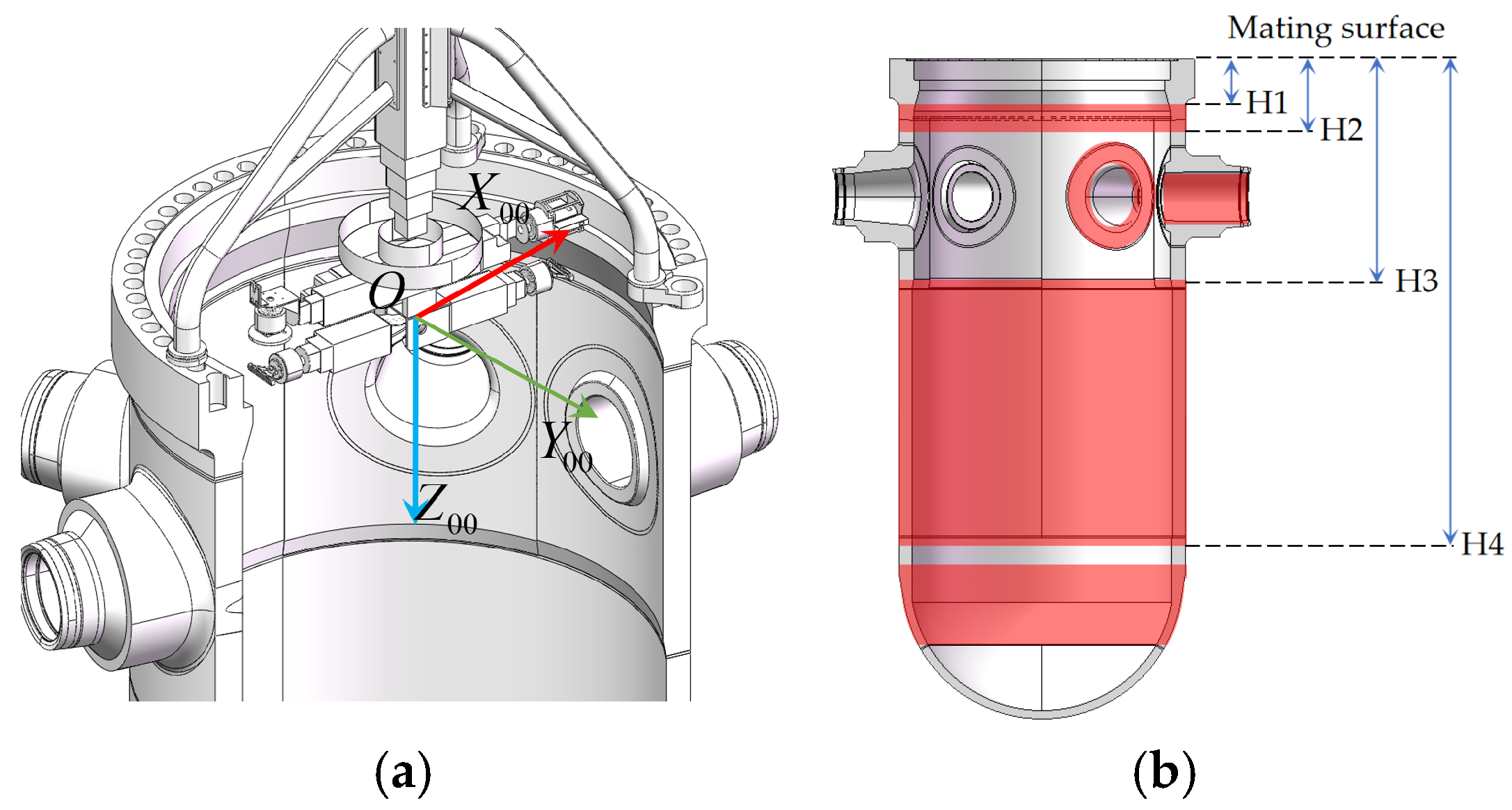
According to the inspection regions outlined above, mathematical modeling was carried out for the seven regions. Using the center position of the mating surface as the origin to establish the coordinate system, the X 00 -axis points to the center of the first flange threaded hole, the Z 00 -axis is vertically oriented downward, and the Y 00 -axis is established based on the right-hand system, as shown in Figure 13a. In addition, the upper and lower boundaries of the area divided in the front part of the article in the Z 00 -axis direction are marked as H1–H4, as shown in Figure 13b.
Region 1 is a cylindrical surface, so its mathematical expression in the coordinate system can be obtained as
x 2 + y 2 = R 2 H 1 z H 2
where R = 2000   mm , H 1 = 425   mm , H 2 = 685   mm .
Region 2 is similar to Region 1, so its mathematical expression in the coordinate system is
x 2 + y 2 = R 2 H 3 z H 4
where R is the diameter of the inner diameter of the pressure vessel, and its size is 2000   mm , H 3 = 3150   mm , and H 4 = 7550   mm .
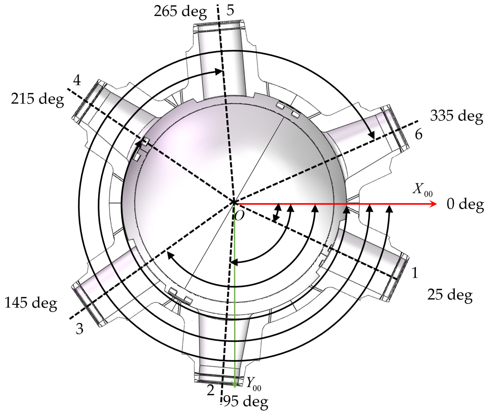
The inspection scope of Region 3 encompasses the nozzle connection area between the main pipelines and the cylindrical shell. Six nozzles with bore diameters ranging from 700 mm to 750 mm are distributed along the pressure vessel shell. In the top view, these nozzles are sequentially numbered in a clockwise direction starting from No. 1, with angular positions relative to the X 00 -axis O X 00 Y 00 Z 00 at 25°, 95°, 145°, 215°, 265°, and 335°, respectively, as illustrated in Figure 14.
Its mathematical expression in the coordinate system is
x 2 sin 2 θ + 2 x y sin θ cos θ + y 2 cos 2 θ + z 2 = r 2 R 2 x 2 + y 2 = R 1 2
In the formula, r represents the inner radius of the pipe wall at the inlet and outlet, while R 1 denotes the farthest position from the inlet and outlet that the manipulator needs to inspect, with a value of 3100 mm. θ i is the angle between each nozzle and the x -axis, and its value in degrees is 25°, 95°, 145°, 215°, 265°, and 335°, which corresponds to the mathematical expressions for nozzles numbered No. 1 to No. 6, respectively.
The inspection scope of Region 4 is the area comprising the rounded corner of the barrel side at the connection with the nozzle extending outward from the curved circular area, whose mathematical expression in the coordinate system is
x 2 + y 2 = R 2 r 2 x 2 sin 2 θ + 2 x y sin θ cos θ + y 2 cos 2 θ + z 2 r 1 2
where r 1 = 720   mm .
The inspection area of Region 5 is the bottom head annular weld as well as the bottom head area, which has the following mathematical expression in the coordinate system:
x 2 + y 2 = R 3 2 7100 z 8000
Given the intractability of analytical mathematical modeling for Regions 6 and 7 (saddle-shaped spatial geometries with a non-uniform curvature), empirical data acquisition via multi-sensor arrays is implemented to extract critical geometric and defect parameters. The acquired datasets serve as input conditions for subsequent dynamic simulation experiments.

4.2. The Traversing Evaluation Indicators

The traversal rate, denoted as J c , is defined as the ratio of the single-pass traversed area s c to the whole inspection area s w when an NDT robot completes full-coverage inspection using a traversal algorithm. A higher J c value indicates broader inspection coverage and superior detection effectiveness in path planning. Mathematically,
J c = s c s w × 100 %

4.3. The Comparison of Traversal Methods

To empirically determine the most efficient and applicable traversal pattern for each specific region, a series of physical experiments was conducted on a full-scale RPV mockup. The mockup, constructed from carbon steel, accurately replicates the geometric features and weld configurations of an actual reactor pressure vessel. The robotic system was equipped with ultrasonic probes with a central frequency of 2.5 MHz, and all tests were performed at a standard scanning speed of 80 mm/s to ensure data integrity and consistency for a fair comparison.
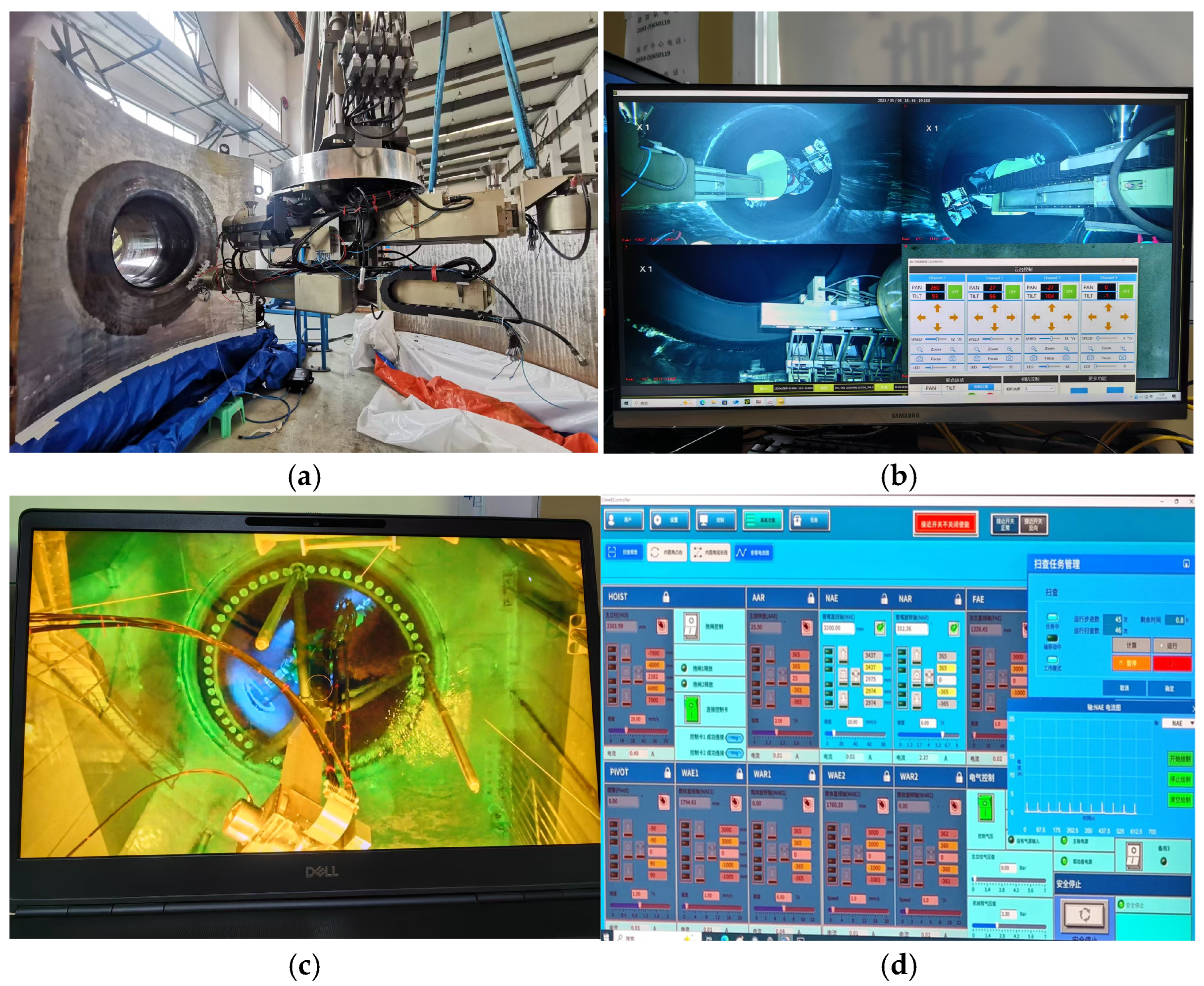
The inspection process was managed through a custom control interface that enabled precise parameter setting and trajectory execution. For instance, to evaluate the circular scanning pattern for the nozzle-to-safe end weld (a subset of Region 3), the inspection plan was executed as follows: the column sleeve was first extended to position the nozzle inspection arm at the nozzle entrance. The Arm Axial Rotator (AAR) was then rotated to 25° to align with the target nozzle. Subsequently, the arm itself was extended 3200 mm into the nozzle. Finally, a full 360°rotation of the Nozzle Axial Rotator (NAR) was performed. This level of precise, programmable control was applied to test all traversal patterns (spiral, transverse meander, longitudinal meander, and circular) in their respective regions.
The superiority of a particular pattern for a given surface type was not a single observation but a consistent result across multiple experiments. This repeatability confirms the statistical reliability and robustness of our conclusions regarding path adaptability.
The full-coverage path planning commonly employs spiral traversal patterns (Figure 15a) and meander linear traversal patterns. The spiral pattern refers to the robot performing concentric spiral movements within sub-regions: starting from the initial point, the robot moves in a tangent direction at constant velocity and completes each loop through 90° turns, progressively contracting toward the innermost circle to achieve full sub-region coverage. The meander linear pattern initiates with vertical upward motion from the starting point, followed by two consecutive 90° turns at sub-region boundaries to reverse direction, forming reciprocating vertical trajectories until full-coverage inspection is completed.
For the internal fillet zone at the nozzle-to-shell weld, the spiral traversal pattern scanning method can be reconfigured into a combined circular path with radial stepping motion. As shown in Figure 15d, this hybrid approach executes concentric circular trajectories while incrementally stepping radially outward, ensuring full coverage of the geometrically complex fillet region. This method is also a variation of the method in Figure 15a, and its basic path is similar.
For cylindrical surfaces (e.g., shell or nozzle bore inside areas), the meander strategy further divides into transverse and longitudinal modes:
Transverse meander traversal: the robotic arm performs full circumferential rotation followed by short-axis feed increments. Longitudinal meander traversal: long-axis feed motions alternate with angular position adjustments. These motion vector orientations are schematically illustrated in Figure 15b and Figure 15c, respectively.
The full-coverage inspection is generally divided into two types of scanning methods. One is called “detection”, which is generally used in situations where the working environment requires low scanning accuracy. The other is called “sizing” and is generally used when the work environment requires higher scanning accuracy.
Considering the actual work requirements and operational scenarios for shell and nozzle inspection, a comparative study of the four traversal methods was conducted. Region 1 and Region 2 represent typical cylindrical working conditions, while Region 3 and Region 4 represent typical saddle surface working conditions, and Region 5 represents typical hemispherical surface working conditions. We conducted testing experiments on these four traversal methods, as shown in Figure 15a–d. The initial stepping speed of the robotic arm was set to determine the path length, turning radius, operation length, and traversal rate during the inspection process (Figure 16).
In field-test conditions, the spiral traversal pattern can achieve full coverage in cylindrical, saddle, and hemispherical surfaces. However, due to the motion characteristics of the spiral traversal pattern, as the inspection position gradually approaches the inner regions, the turning frequency increases significantly. To reduce the impact sustained by the arms during directional changes, deceleration is required before each turn. This results in a decreasing proportion of full-speed operation in the robotic arm’s inner regions, leading to a gradual decline in detection efficiency and, consequently, prolonging the overall operation time.
Simulation tests were conducted using other full-area traversal methods under identical working conditions. During the inspection of Region 2, the efficiency improvement from the reduced turns was no longer obvious. For typical working conditions, the transverse meander traversal pattern was shown to be more efficient than the longitudinal meander traversal pattern, as the robotic arm spends a greater proportion of time operating at full speed along a section of the trajectory, with fewer turns.
As demonstrated in the above analysis, the transverse meander traversal pattern exhibits significant advantages in NDT of RPVs across cylindrical and hemispherical working conditions. Specifically, it achieves full coverage with fewer directional turns and reduced operational duration, thereby ensuring higher efficiency and inspection quality. This pattern is therefore recommended as the primary scanning strategy for detection methods. In contrast, the longitudinal meander traversal pattern, due to its superior capability for inspecting fine defects, is more suitable for sizing scanning methods.
Due to the void-like geometry of the saddle-shaped weld embedded in the cylindrical shell, linear scanning methods fail to achieve full inspection coverage in this region. In contrast, although the circular scanning method exhibits lower scanning efficiency, it ensures full coverage by dynamically adapting to the saddle-shaped surface curvature. Consequently, the circular scanning method is adopted here, with the robotic sensor module’s speed set to 0–150 mm/s, as shown in Figure 15d.

4.4. The Inspection Path Planning Method

By employing the transverse meander traversal pattern, this study analyzes the structural characteristics and inspection challenges across different regions to propose an adaptive full-coverage inspection path-planning approach.
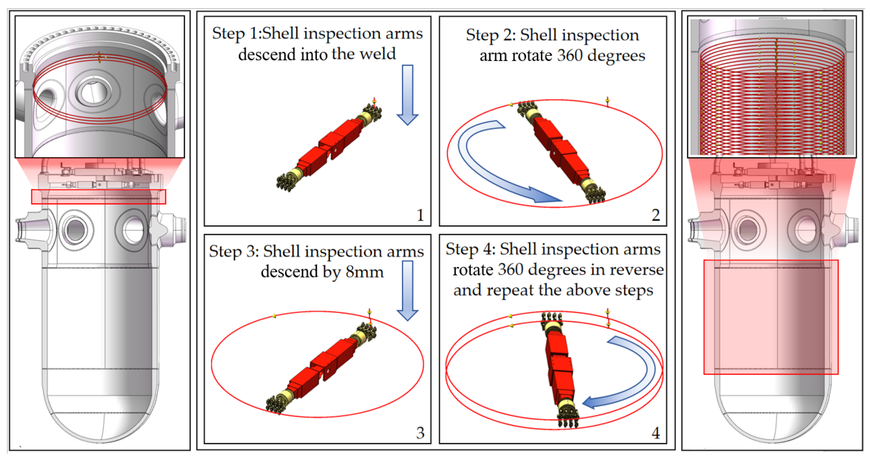
The inspection scope of Region 1 encompasses thick-walled low-alloy steel butt welds and the adjacent areas spanning 300 mm above and below the welds, which exhibit bilateral symmetry along the weld line. The inspection area of Region 2 encompasses the cylindrical shell between two circumferential welds, with the active core region distributed within the inspection zone. All operational zones exhibit a regular cylindrical geometry. Consequently, a rotary motion combined with axial feed is adopted for detection. The procedure is outlined below.
The robot positions the shell inspection arm at a predefined height above the circumferential weld, leveraging the pressure vessel’s cylindrical symmetry. The arm performs a full 360° circumferential rotation to scan the target area. Upon completing one rotation, the arm steps down axially by 8 mm in the Z 00 direction. The cycle repeats iteratively, generating a grid-like scanning pattern across the cylindrical surface, as illustrated in Figure 17.
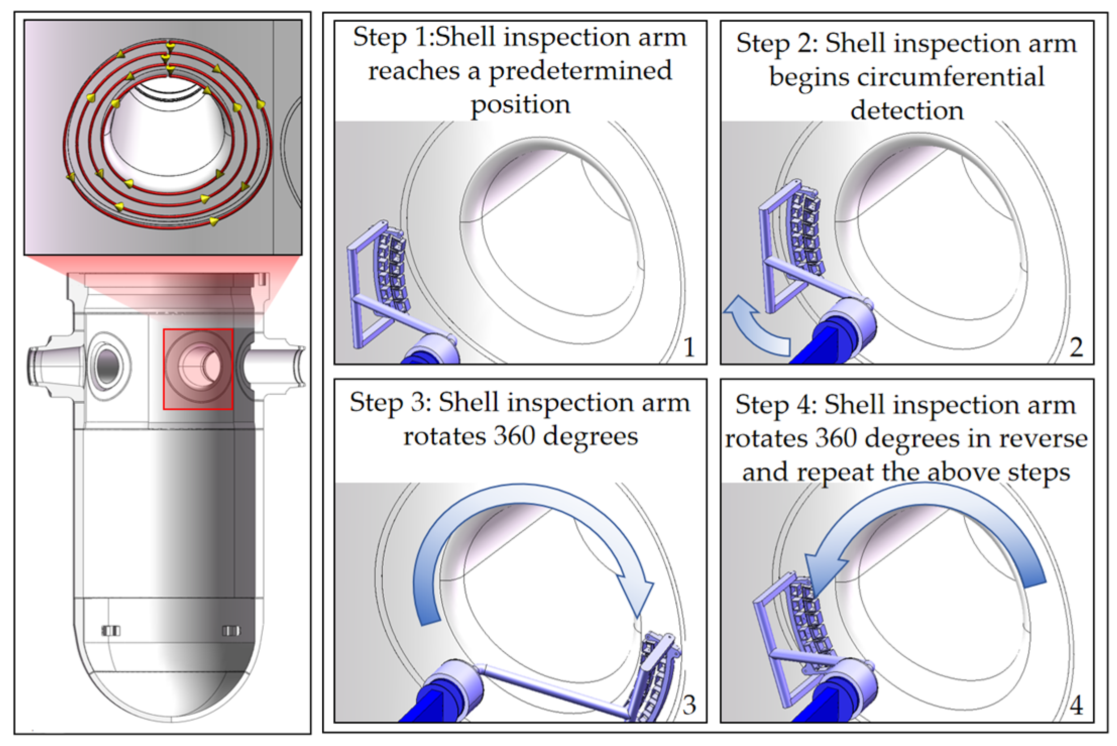
As shown in Figure 18, the inspection of Region 3 focuses on the nozzle-to-shell weld (nozzle bore side). Due to abrupt changes in wall curvature and the need to maintain a probe edge safety margin (typically 3–5 mm), conventional inspection methods similar to Regions 1 for this area may result in missed inspection of critical weld zones. To address this problem, a saddle-shaped trajectory feeding method is implemented as follows:
Firstly, the nozzle inspection arm positions the probe 1000 mm inward from the nozzle centerline. Then, the probe initiates continuous clockwise circumferential rotation while the robotic arm reciprocates axially along the shell axis, forming a saddle-shaped scanning trajectory. Upon completing one full cycle, the robotic arm retreats 10 mm toward the reinforcement part to initiate the next scanning layer. This method achieves higher coverage than traditional circular trajectories, significantly improving defect-detection rates in geometrically complex weld regions.
As illustrated in Figure 19, the inspection scope of Region 4 covers an annular curved surface region extending 750 mm radially outward from the fillet at the nozzle-to-shell junction. Due to its externally convex, saddle-shaped geometry, conventional probes require grid-scanning similar to Regions 1 and 2, resulting in a prolonged inspection time, low efficiency, and complex path planning. To address these limitations, the detection probe is upgraded with adaptive radial extension capability, enabling the following optimized protocol.
Firstly, the probe holder extends radially from the fillet to initiate scanning. A clockwise circumferential scan is performed while the robotic arm feeds axially. Upon completing one full rotation, the probe holder retracts radially by 8 mm and executes a counterclockwise circumferential scan. This iterative reciprocation (radial stepping + bidirectional rotation) continues until full coverage is achieved.
This probe holder modification improves inspection efficiency and enhances defect-detection accuracy in geometrically complex saddle regions.
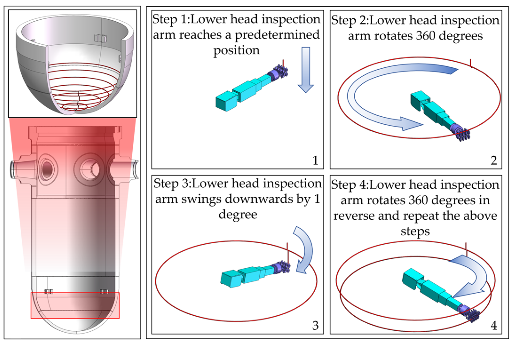
As shown in Figure 20, the inspection scope of Region 5 includes the lower head weld and the lower head region. The lower head exhibits a regular hemispherical geometry, necessitating coordinated swing of the dedicated inspection robotic arm for efficient detection. The protocol is implemented as follows:
The robotic arm is centered at the spherical origin of the lower head and aligned horizontally. A clockwise circumferential scan is performed to cover the target weld zone. After accompanying the inspection, the arm tilts downward by 1° and executes a counterclockwise circumferential scan. This iterative reciprocation (angular stepping + bidirectional rotation) continues until full hemispherical coverage is achieved.
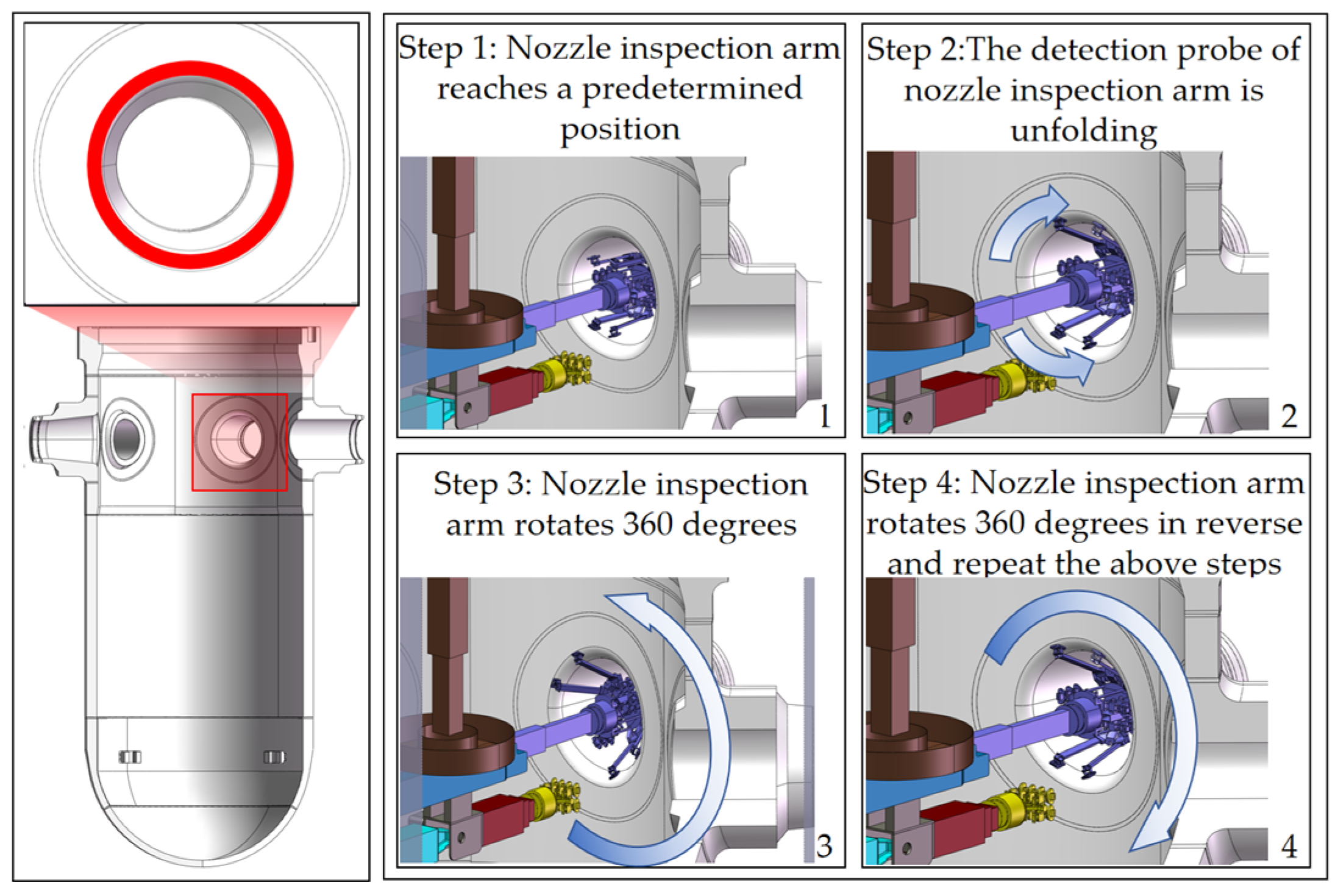
As illustrated in Figure 21, the inspection scope of Region 6 encompasses the inner radius zone formed at the confluence of the inlet nozzle and the cylindrical shell. This surface exhibits a saddle-shaped spatial geometry, necessitating synchronized swing motion of the nozzle inspection robotic arm for efficient detection. The process is executed as follows:
The robotic arm aligns with the nozzle centerline and advances axially toward the nozzle orifice by a predefined distance. The detection probe deploys radially to engage the fillet zone. A full 360° circumferential scan is performed to ensure probe stability.
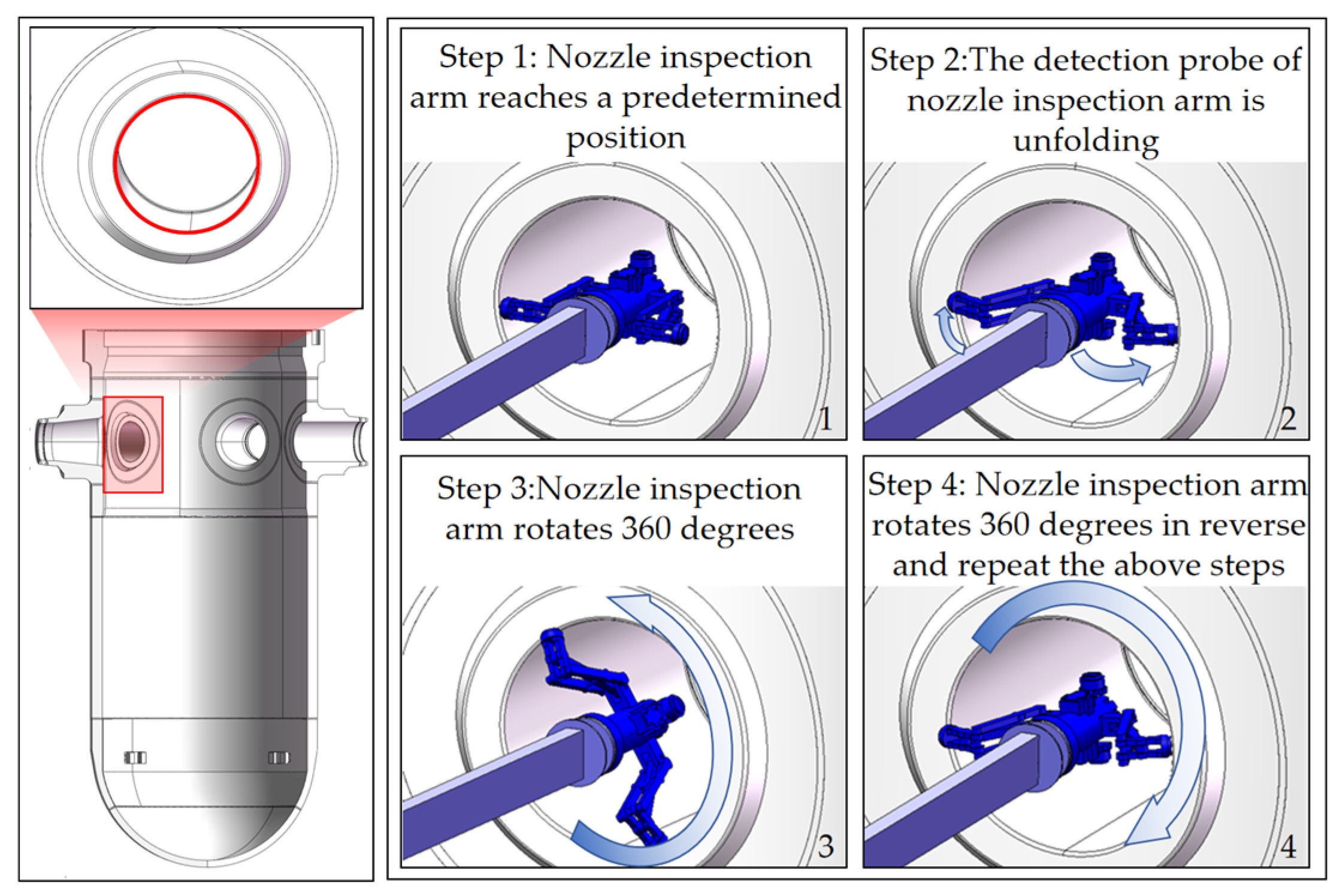
Similarly, as shown in Figure 22, Region 7 involves the inner radius zone at the outlet nozzle-to-shell junction. Due to its reduced dimensional scale, a miniature probe assembly is employed, featuring adaptive curvature matching to maintain consistent probe–surface coupling.

4.5. The Inspection Trajectory Interpolation Method

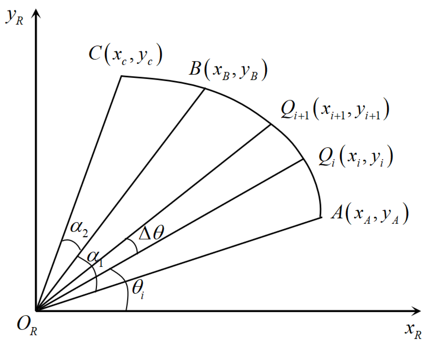
Due to the working characteristics of the NDT robot during inspection of the RPV, the end-effector inspection probe must follow a Cartesian-space trajectory along the circular inner wall during inspections. To enhance the motion accuracy and prevent collisions between the probe and the RPV inner wall, this study proposes a Cartesian-space arc interpolation algorithm for precise trajectory calculation of the robotic end-effector.
A circle can be defined by three points: When we establish points A x A , y A , B x B , y B , and C x C , y C that the robot needs to pass through in space, a circular arc with a radius of R can be determined based on these three points, as illustrated in Figure 23.
According to the geometric relationship in Figure 23, the central angle from point A to point B is denoted as α 1 , the central angle from point B to point C is denoted as α 2 , and the central angle from point A to point C is denoted as α 3 . There are the following derivations:
α 1 = arccos x 2 x 1 2 + y 2 y 1 2 2 R 2 2 R 2 α 2 = arccos x 3 x 2 2 + y 3 y 2 2 2 R 2 2 R 2
α 3 = α 1 + α 2
By determining the movement speed v of the inspection arm end along the arc and the time interval Δ t between every two interpolation points, the displacement Δ θ that occurs during this time interval Δ t is as follows:
Δ θ = Δ t × θ ˙ R
The number of interpolations N for the arc is calculated as follows:
N = α Δ θ + 1
For circular interpolation, the coordinates of the interpolation points Q x i + 1 , y i + 1 are as follows:
x i + 1 = R cos θ i + Δ θ = x i cos Δ θ y i sin Δ θ y i + 1 = R cos θ i + Δ θ = y i cos Δ θ x i sin Δ θ

5. Experiments and Conclusions

Following the empirical determination of the optimal traversal patterns through physical experiments in Section 4.3, this section focuses on the simulation-based validation of the resulting full-coverage inspection paths. The dynamic simulation was conducted using ADAMS, with simplified imported 3D models of the robot and RPV. The joint drive functions were set according to the kinematic model and the optimized paths identified in the previous section.
For different inspection areas, the Cartesian-space arc interpolation method described in Section 4.5 was employed for trajectory simulation. The simulated trajectories for all seven regions are presented and analyzed below, validating the feasibility of the planned paths and their expected 100% coverage prior to physical deployment.
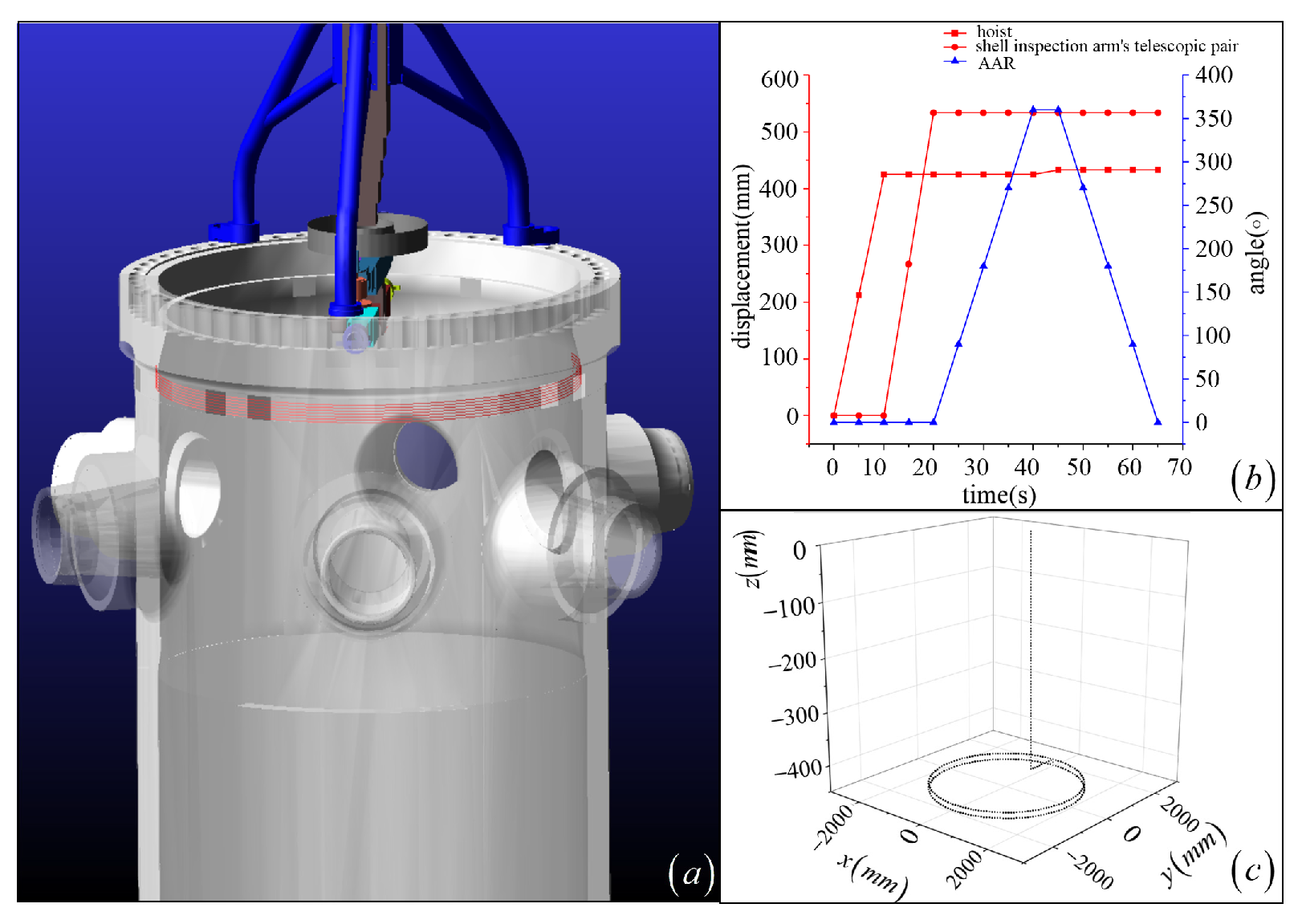
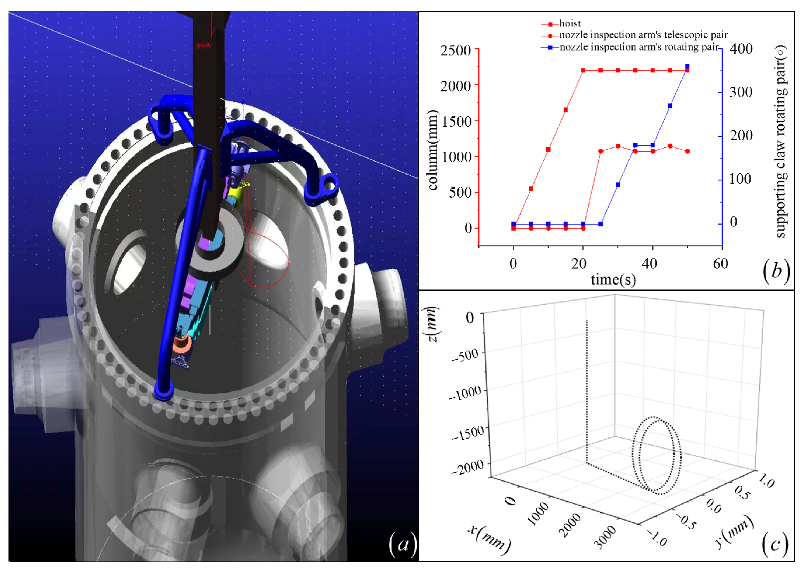
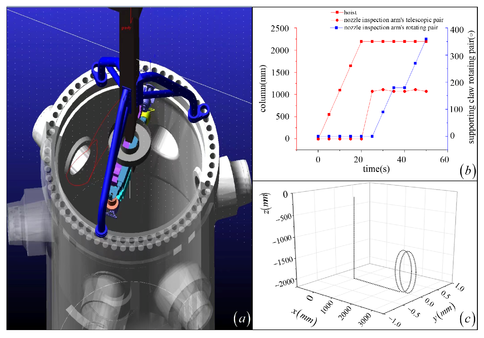
For Regions 1 and 2, the inspection arm uses axial stepping (8 mm per cycle) combined with circumferential rotation to perform grid-patterned scanning. The simulated inspection trajectories are illustrated in Figure 24a and Figure 25a, and the joint rotation angles of the robot arm during the first two motion cycles are plotted in Figure 24b and Figure 25b. The resultant end-effector trajectory coordinates are shown in Figure 24c and Figure 25c. By inputting the joint angles into the kinematic model, the actual end-effector trajectory matches the simulated path precisely, thereby validating the feasibility of the proposed trajectory-planning method.
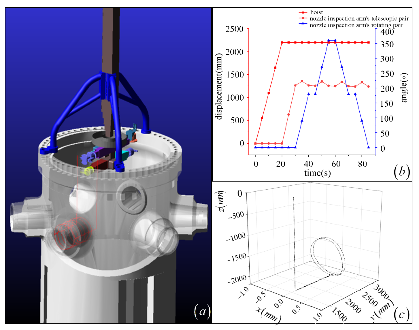
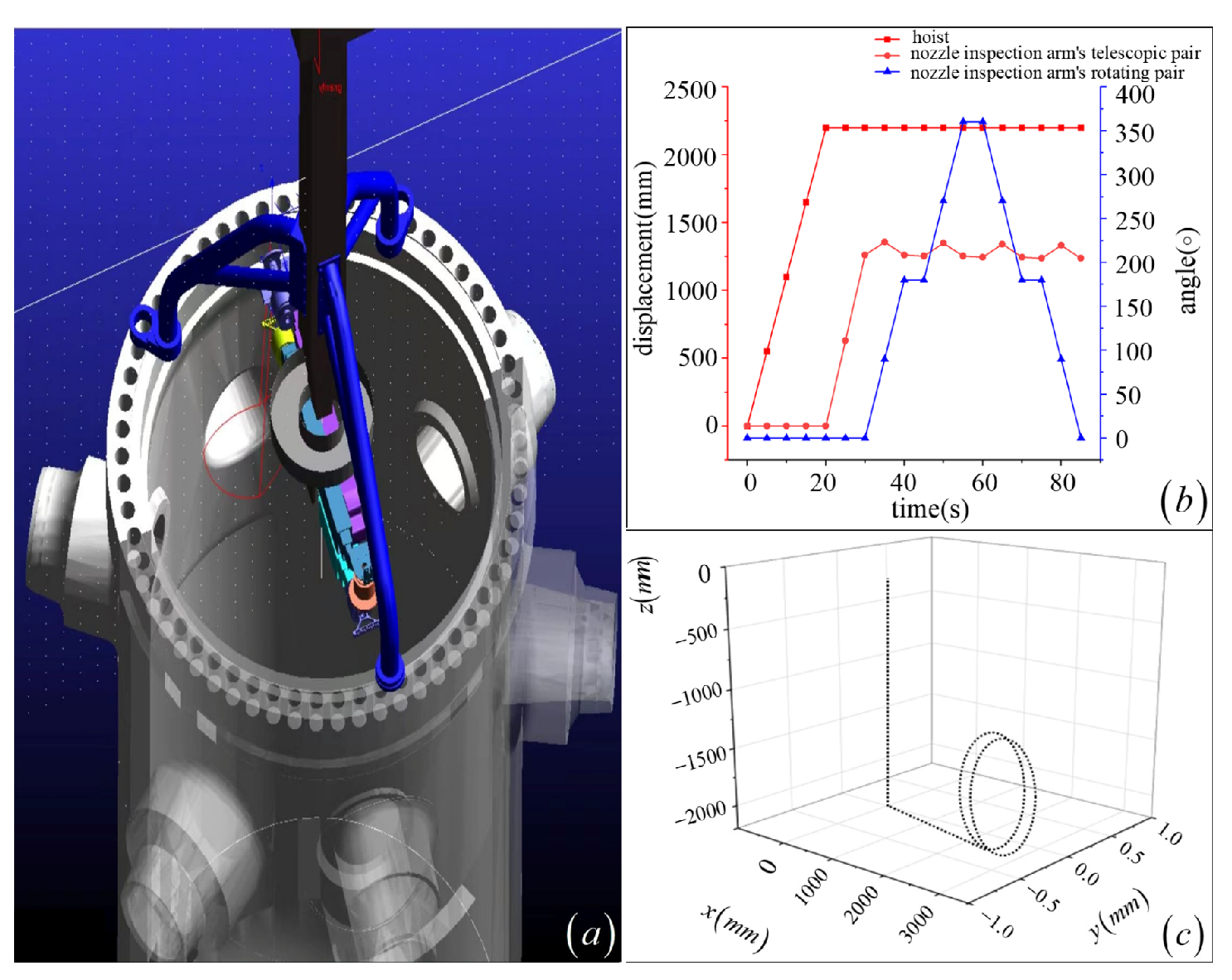
For Regions 3 and 4, the inspection arm uses a saddle-shaped trajectory feeding method, as shown in Figure 26 and Figure 27. Similarly, it proves the feasibility of the trajectory-planning method.
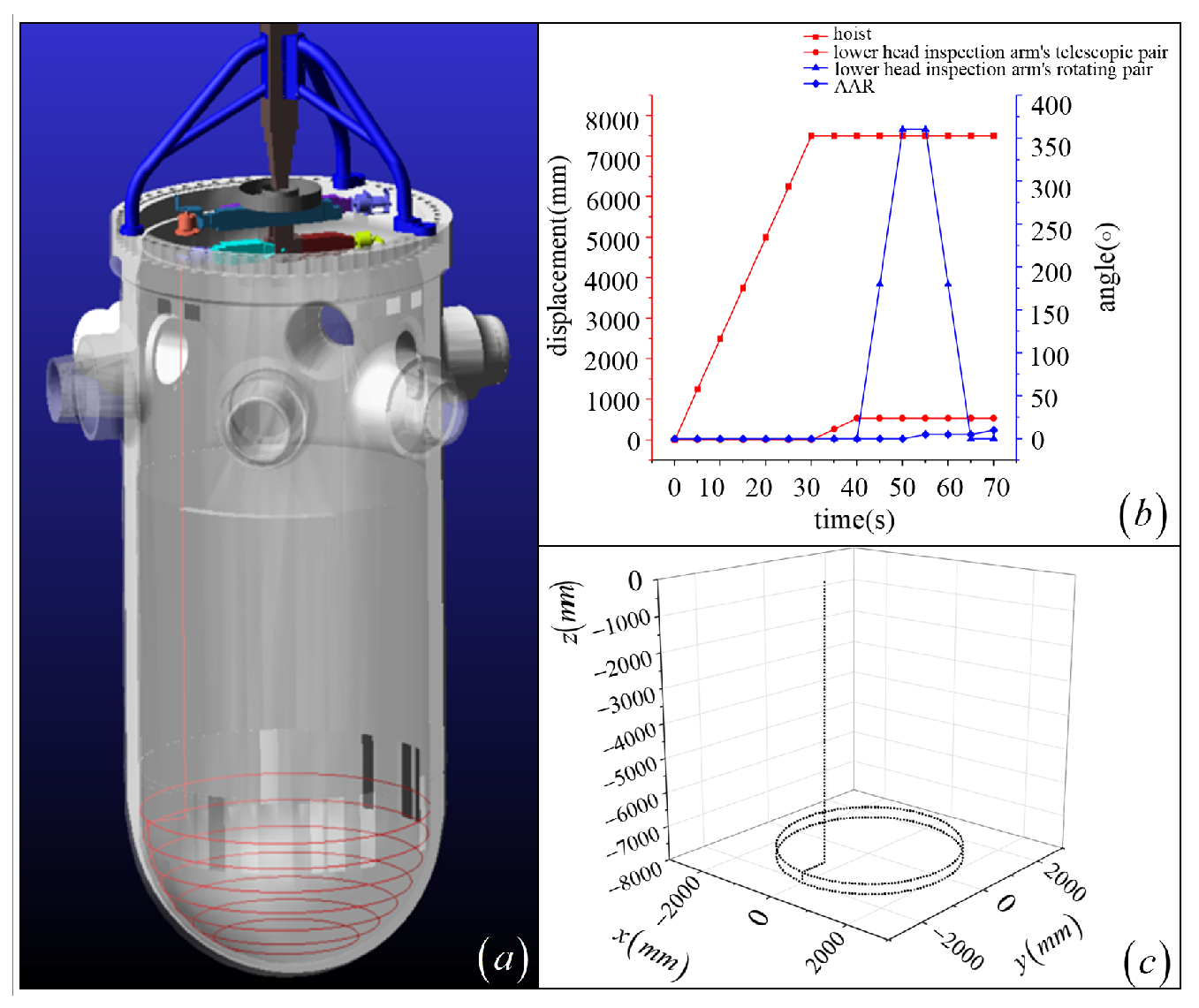
For Region 5, a swing-stepping and circumferential-rotation inspection mode is used for grid-patterned inspection, as shown in Figure 28. Similarly, the result proves the feasibility of the trajectory-planning method.
For Regions 6 and 7, the inspection arm employs a saddle-shaped trajectory feeding method for detection, as illustrated in Figure 29 and Figure 30. The result proves the feasibility of the trajectory-planning method.
By providing a dense set of interpolation points for the preset trajectory in the simulation software, while considering interpolation accuracy and computational load, the descent distance of the inspection arm and the stepping data are planned. Based on the simulation trajectory, inspection indicators for traversal rate across different areas are generated, as shown in Table 3.
The coverage rate of traditional methods in regions 4, 6, and 7 is 0%, partly because, according to previous inspection standards (such as the French RSEM Code), these regions were not within the mandatory inspection scope. In contrast, under the new inspection standards (such as the American ASME code), these regions now require inspection. The inspection trajectories for Regions 1, 2, and 5 benefit from geometric symmetry, enabling a higher traversal rate. By adopting a saddle-shaped inspection trajectory, Regions 3, 4, 6, and 7 effectively improved the inspection traversal rate compared to the traditional circular trajectory. For example, the simulation of the Region 3 inspection process indicates a 6% increase over the traditional circular trajectory inspection method [10].
A saddle-shaped inspection path-planning method with symmetric motion patterns was proposed for the NDT robot in RPV, further improving inspection coverage and efficiency. This method uses traditional path-planning methods rather than neural network-based methods. Although neural networks have shown great potential for path planning in mobile robots, the determinacy and verifiability of these methods are crucial for nuclear inspection applications. In high-risk environments such as nuclear power plants, operational reliability and safety are crucial, and the predictable performance of traditional methods surpasses the potential benefits of more intelligent but less deterministic neural network methods. Future work will consider integrating intelligent methods into these critical tasks once their reliability is fully determined. By optimizing the inspection path effectively, the time required for path inspection and replanning was dramatically reduced, providing a new approach for subsequent NDT of RPVs in nuclear power plants.

Supplementary Materials

The following supporting information can be downloaded at: https://www.mdpi.com/article/10.3390/sym17111995/s1, Video S1: Supplementary_Video_1_Comment 1.3.

Author Contributions

Conceptualization, M.H. and H.C.; method, H.C.; software, J.J.; validation, X.Z. (Xiaoyang Zhao) and J.Y.; formal analysis, Z.Z.; investigation, M.H.; resources, X.Z. (Xiaobing Zhang); data curation, Z.Z.; writing—original draft preparation, M.H.; writing—review and editing, Z.Z.; visualization, X.Z. (Xiaobing Zhang); supervision, H.C.; project administration, X.Z. (Xiaobing Zhang); funding acquisition, J.Y. All authors have read and agreed to the published version of the manuscript.

Funding

This work was supported by the National Key R&D Program of China (grant No. 2022YFB4701100).

Data Availability Statement

The original contributions presented in this study are included in the article/Supplementary Materials. Further inquiries can be directed to the corresponding authors.

Acknowledgments

The authors would like to thank Jianrong Wu of CGN Inspection Technology Co., Ltd., for his guidance and fruitful discussion.

Conflicts of Interest

Authors Mr. Maocheng Hong and Dr. Huaidong Chen were employed by CGN Inspection Technology Co., Ltd. The remaining authors declare that the research was conducted in the absence of any commercial or financial relationships that could be construed as a potential conflict of interest.

References

  1. Fernandez-Arias, P.; Vergara, D.; Orosa, J.A. A Global Review of PWR Nuclear Power Plants. Appl. Sci. 2020, 10, 4434. [Google Scholar] [CrossRef]
  2. Huang, S.; Sun, H.; Wang, K.; Zhao, W.; Peng, L. Nondestructive Testing and Condition Monitoring of Pressurized Water Reactor Nuclear Power Plants: A Review. J. Mech. Eng. 2022, 58, 1–13. [Google Scholar]
  3. Wen, S.; Gao, X.; Zhang, R.; Fan, K.; Jia, B.; Jing, J.; Liu, F.; Tian, X. Study on the influences of RPV deformation on CHF under IVR conditions. Front. Energy Res. 2023, 11, 1087135. [Google Scholar] [CrossRef]
  4. Aksenov, P.L.; Komolov, I.A.; Molodov, P.A. Development of a Risk Monitoring Model for NPPs with a VVER-440 Reactor. At. Energy 2023, 133, 136–141. [Google Scholar] [CrossRef]
  5. Emerson, J.N.; Marrero-Jackson, E.H.; Nemets, G.A.; Okuniewski, M.A.; Wharry, J.P. Nuclear Reactor Pressure Vessel Welds: A Critical and Historical Review of Microstructures, Mechanical Properties, Irradiation Effects, and Future Opportunities. Mater. Des. 2024, 244, 113134. [Google Scholar] [CrossRef]
  6. Cheng, Y.; Huang, M.; Li, Y.; Liu, W.; Wang, B.; Meng, X.; Ouyang, X. Influence of interaction among multiple cracks on crack propagation in nozzle corner of reactor pressure vessel. Ann. Nucl. Energy 2023, 194, 110142. [Google Scholar] [CrossRef]
  7. American Society of Mechanical Engineers. ASME BPVC Section XI: Rules for Inservice Inspection of Nuclear Power Plant Components; ASME: New York, NY, USA, 2023. [Google Scholar]
  8. Ducros, C.; Hauser, G.; Mahjoubi, N.; Girones, P.; Boisset, L.; Sorin, A.; Jonquet, E.; Falciola, J.M.; Benhamou, A. RICA: A Tracked Robot for Sampling and Radiological Characterization in the Nuclear Field. J. Field Robot. 2017, 34, 583–599. [Google Scholar] [CrossRef]
  9. Kim, J.H. Reactor nozzle inspection based on the laser-guided mobile robot. J. Field Robot. 2018, 35, 1155–1172. [Google Scholar] [CrossRef]
  10. Hong, M.; Li, Y.; Yan, J.; Ma, G.; Ye, X.; Chen, H.; Zhang, X. Simulation and analysis of full-coverage ultrasonic signal detection for reinforcement part of nuclear reactor pressure vessel outlet nozzle. Int. J. Press. Vessel. Pip. 2025, 216, 105462. [Google Scholar] [CrossRef]
  11. Sung, M.; Choi, Y. Algorithmic Modified Denavit–Hartenberg Modeling for Robotic Manipulators Using Line Geometry. Appl. Sci. 2025, 15, 4999. [Google Scholar] [CrossRef]
  12. Wang, J.; Liang, F.; Zhou, H.; Yang, M.; Wang, Q. Analysis of position, pose and force decoupling characteristics of a 4-UPS/1-RPS parallel grinding robot. Symmetry 2022, 14, 825. [Google Scholar] [CrossRef]
  13. Zhong, F.; Liu, G.; Lu, Z.; Han, Y.; Liu, F.; Ye, T. Inverse kinematics analysis of humanoid robot arm by fusing denavit-hartenberg and screw theory to imitate human motion with kinect. IEEE Access 2023, 11, 67126–67139. [Google Scholar] [CrossRef]
  14. Shin, H.; Jeong, K.M.; Jung, S.; Kim, S. Development of a steam generator tube inspection robot with a supporting leg. Nucl. Eng. Technol. 2009, 41, 125–134. [Google Scholar] [CrossRef]
  15. Zheng, C.; Zou, L.; Zheng, Z.; Xue, X. Kinematics modeling and singularity analysis of a 6-DOF all-metal vibration isolator based on dual quaternions. Symmetry 2023, 15, 562. [Google Scholar] [CrossRef]
  16. Cho, Y.; Do, H.M.; Cheong, J. Screw based kinematic calibration method for robot manipulators with joint compliance using circular point analysis. Robot. Comput. Integr. Manuf. 2019, 60, 63–76. [Google Scholar] [CrossRef]
  17. Sheng, Z.; Wang, Y.; Li, S.; Yang, J.; Xie, H.; Lu, X. Research on kinematics modeling and path planning of a hyper-redundant continuum robot. Proc. Inst. Mech. Eng. Part C J. Mech. Eng. Sci. 2024, 238, 5880–5890. [Google Scholar] [CrossRef]
  18. Yang, H.; Xia, C.; Wang, X.; Xu, W.; Liang, B. An efficient solver for the inverse kinematics of cable-driven manipulators with pure rolling joints using a geometric iterative approach. Mech. Theory 2024, 196, 105611. [Google Scholar] [CrossRef]
  19. Park, S.O.; Lee, M.C.; Kim, J. Trajectory Planning with Collision Avoidance for Redundant Robots Using Jacobian and Artificial Potential Field-based Real-time Inverse Kinematics. Int. J. Control Autom. Syst. 2020, 18, 2095–2107. [Google Scholar] [CrossRef]
  20. Chen, Y.; Luo, X.; Han, B.; Jia, Y.; Liang, G.; Wang, X. A general approach based on Newton’s method and cyclic coordinate descent method for solving the inverse kinematics. Appl. Sci. 2019, 9, 5461. [Google Scholar] [CrossRef]
  21. Dereli, S.; Köker, R. A meta-heuristic proposal for inverse kinematics solution of 7-DOF serial robotic manipulator: Quantum behaved particle swarm algorithm. Artif. Intell. Rev. 2020, 53, 949–964. [Google Scholar] [CrossRef]
  22. Lan, L.; Li, H.; Yang, W.; Qiao, Y.; Qi, Z. Learning the Kinematics of a Manipulator Based on VQTAM. Symmetry 2020, 12, 519. [Google Scholar] [CrossRef]
  23. Liu, F.; Gao, C.; Liu, L. SK-PSO: A Particle Swarm Optimization Framework with SOM and K-Means for Inverse Kinematics of Manipulators. Symmetry 2024, 16, 1667. [Google Scholar] [CrossRef]
  24. Hassan, A.A.; El-Habrouk, M.; Deghedie, S. Inverse kinematics of redundant manipulators formulated as quadratic programming optimization problem solved using recurrent neural networks: A review. Robotica 2020, 38, 1495–1512. [Google Scholar] [CrossRef]
  25. Vertesy, G.; Rabung, M.; Gasparics, A.; Uytdenhouwen, I.; Griffin, J.; Algernon, D.; Gronroos, S.; Rinta-Aho, J. Evaluation of the embrittlement in reactor pressure-vessel steels using a hybrid nondestructive electromagnetic testing and evaluation approach. Materials 2024, 17, 1106. [Google Scholar] [CrossRef]
  26. Vasiljevic, G.; Brkic, V.; Postruzin, Z.; Kovaxix, Z. 3D Model-Based Nondestructive Scanning of Reactor Pressure Vessels with 6DoF Robotic Arms. In Proceedings of the 2022 IEEE International Symposium on Safety, Security, and Rescue Robotics (SSRR), Sevilla, Spain, 8–10 November 2022. [Google Scholar]
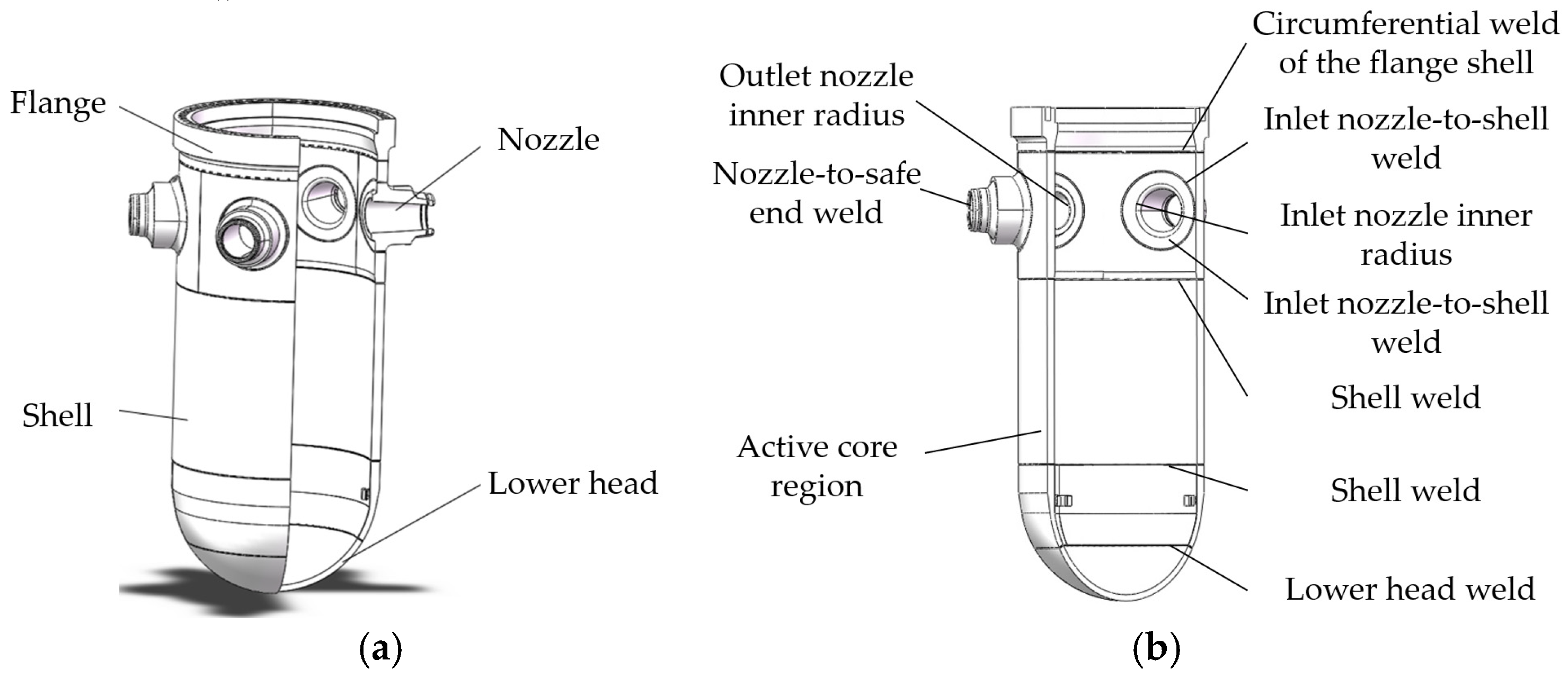
Figure 1. RPV structure: (a) the main components of RPV; (b) the types of welds.
Symmetry 17 01995 g001
Figure 2. NDT robot for RPV.
Symmetry 17 01995 g002
Figure 3. Shell inspection arms.
Symmetry 17 01995 g003
Figure 4. Nozzle inspection arm: (a) nozzle-to-shell weld inspection (nozzle bore side); (b) nozzle-to-shell weld inspection (shell side).
Symmetry 17 01995 g004
Figure 5. Lower head weld inspection arm.
Symmetry 17 01995 g005
Figure 6. The control system architecture of the multi-arm NDT robot.
Symmetry 17 01995 g006
Figure 7. Simplified model of the Type I inspection arm.
Symmetry 17 01995 g007
Figure 8. Inverse kinematics model of the Type I inspection arm.
Symmetry 17 01995 g008
Figure 9. The simplified model of the Type II inspection arm.
Symmetry 17 01995 g009
Figure 10. The inverse kinematics model of the Type II inspection arm.
Symmetry 17 01995 g010
Figure 11. The solution of angle θ 9 using the double-projection method: (a) the relationship of the coordinate axes in the plane x 9 O 9 y 9 ; (b) diagram of the x 9 ini -axis in the plane O 0 O 8 O 9 .
Symmetry 17 01995 g011
Figure 12. UT inspection region division for RPV.
Symmetry 17 01995 g012
Figure 13. RPV coordinate system: (a) global coordination system; (b) benchmark for the Z 00 -axis.
Symmetry 17 01995 g013
Figure 14. RPV nozzles.
Symmetry 17 01995 g014
Figure 15. Path patterns: (a) spiral traversal pattern; (b) longitudinal meander traversal; (c) transverse meander traversal; (d) circular scanning pattern.
Symmetry 17 01995 g015aSymmetry 17 01995 g015b
Figure 16. The implementation and validation of the robotic inspection system. (a) Field deployment in the Reactor Pressure Vessel mockup. (b,c) Execution of path planning. (d) System control interface.
Symmetry 17 01995 g016
Figure 17. The inspection path for Region 1 (resulting in full coverage).
Symmetry 17 01995 g017
Figure 18. The inspection path for Region 3 (resulting in full coverage).
Symmetry 17 01995 g018
Figure 19. The inspection path for Region 4 (resulting in full coverage).
Symmetry 17 01995 g019
Figure 20. The inspection path for Region 5 (resulting in full coverage).
Symmetry 17 01995 g020
Figure 21. The inspection path for Region 6 (resulting in full coverage).
Symmetry 17 01995 g021
Figure 22. The inspection path for Region 7 (resulting in full coverage).
Symmetry 17 01995 g022
Figure 23. The interpolation method.
Symmetry 17 01995 g023
Figure 24. The inspection simulation for Region 1. (a) Robot configuration during inspection; (b) Joint displacement and rotation angle vs. time; (c) End-effector trajectory.
Symmetry 17 01995 g024
Figure 25. The inspection simulation for Region 2. (a) Robot configuration during inspection; (b) Joint displacement and rotation angle vs. time; (c) End-effector trajectory.
Symmetry 17 01995 g025
Figure 26. The inspection simulation for Region 3. (a) Robot configuration during inspection; (b) Joint displacement and rotation angle vs. time; (c) End-effector trajectory.
Symmetry 17 01995 g026
Figure 27. The inspection simulation for Region 4. (a) Robot configuration during inspection; (b) Joint displacement and rotation angle vs. time; (c) End-effector trajectory.
Symmetry 17 01995 g027
Figure 28. The inspection simulation for Region 5. (a) Robot configuration during inspection; (b) Joint displacement and rotation angle vs. time; (c) End-effector trajectory.
Symmetry 17 01995 g028
Figure 29. The inspection simulation for Region 6. (a) Robot configuration during inspection; (b) Joint displacement and rotation angle vs. time; (c) End-effector trajectory.
Symmetry 17 01995 g029
Figure 30. The inspection simulation for Region 7. (a) Robot configuration during inspection; (b) Joint displacement and rotation angle vs. time; (c) End-effector trajectory.
Symmetry 17 01995 g030
Table 1. D-H parameters of planar 4-DOF inspection arms.
Joint No.Joint Type a n
(mm)
α n
(Rad)
d n
(mm)
θ n
(Rad)
Initial Value of Joint Variable Range of Joint Variables
1Prismatic Joint00 d 1 03300 mm d 1 L 1 min , L 1 max
2Revolute Joint0 π / 2 0 θ 2 π / 2 θ 2 π , π
3Prismatic Joint00 d 3 01100 mm d 3 L 3 min , L 3 max
4Revolute Joint000 θ 4 0 θ 4 π , π
Table 2. D-H parameters of planar 5-DOF inspection arms.
Joint No.Joint Type a n
(mm)
α n
(Rad)
d n
(mm)
θ n
(Rad)
Initial Value of Joint VariableRange of Joint Variables
5Prismatic Joint00 d 5 03800 mm d 5 L 5 min , L 5 max
6Revolute Joint0 π / 2 0 θ 6 π / 2 θ 6 π , π
7Revolute Joint0 π / 2 0 θ 7 π / 2 θ 7 π 2 , π
8Prismatic Joint00 d 8 01200 mm d 8 L 8 min , L 8 max
9Revolute Joint000 θ 9 0 θ 9 π , π
Table 3. The inspection data used to determine the traversal rate.
Region No. Traversal   Rate   J c
Traditional MethodNew MethodCoverage Improvement
Region 1100%100%Optimized for higher operational efficiency
Region 2100%100%Optimized for higher operational efficiency
Region 394%100%Eliminated inspection blind spots
Region 40% (Not Required)100%Enabled full coverage as per new standards
Region 5100%100%Optimized for higher operational efficiency
Region 60% (Not Required)100%Enabled full coverage as per new standards
Region 70% (Not Required)100%Enabled full coverage as per new standards
Disclaimer/Publisher’s Note: The statements, opinions and data contained in all publications are solely those of the individual author(s) and contributor(s) and not of MDPI and/or the editor(s). MDPI and/or the editor(s) disclaim responsibility for any injury to people or property resulting from any ideas, methods, instructions or products referred to in the content.