Article

Seismic Response Analysis of Asymmetrical Rectangular Assembly Splicing Subway Station in Soft Soil

1
Engineering Department, Sinohydro Bureau 7 Co., Ltd., Chengdu 610000, China
2
Department of Science and Technology Innovation, Dongguan Institute of Building Research Co., Ltd., Dongguan 523820, China
3
School of Civil Engineering, Beijing Jiaotong University, Beijing 100044, China
*
Author to whom correspondence should be addressed.
Symmetry 2025, 17(11), 1902; https://doi.org/10.3390/sym17111902
Submission received: 14 September 2025 / Revised: 20 October 2025 / Accepted: 4 November 2025 / Published: 7 November 2025
(This article belongs to the Section Engineering and Materials)

Abstract

With advantages in efficiency and sustainability, assembly splicing technology promotes construction industry upgrading. However, research on the seismic response of assembly splicing subway stations (ASS) is particularly scarce. This work studies the asymmetric ASS in soft soil, establishing a refined finite element model with soil–structure interactions. Three seismic records with different frequency characteristics are applied for nonlinear incremental dynamic analysis. Based on the seismic records that produce the most unfavorable seismic response, this research is conducted on the damage distribution characteristics and the mechanical responses. In addition, the influence of the splicing response at different locations on the interlayer displacement and internal forces of structures is systematically studied. The results indicate that when seismic records with low-frequency characteristics are inputted, the ASS structure in soft soil develops into the most unfavorable state. Under strong seismic action, the top joint of the sidewall exhibits significant horizontal sliding and opening, making key areas of weak seismic performance. It also indicates that the interface contact between precast and cast-in-place components is the primary factor that is causing internal force redistribution. This study provides a reference for performance-based seismic design of ASS in soft soil.

1. Introduction

In recent years, prefabricated subway station structures have played an increasingly important role in modern urban rail transit construction due to their excellent waterproofing performance, shorter construction periods, and strong sustainability; thus, they have become a major driving force in promoting the development of urban infrastructure toward greater efficiency and environmental protection [1]. The structural forms for prefabricated subway stations can be categorized into two types: assembly monolithic and assembly splicing structures. The novel assembly splicing subway station is a new type of structure that integrates prefabrication technology with the mechanical characteristics of composite structures. The structure is made up of prefabricated components that are produced by factories, quickly assembled on site, and assembly spliced with precast and cast-in-place concrete. However, soft soil areas are typically characterized by loose strata, low bearing capacity, and a propensity for seismic subsidence or liquefaction during earthquakes, which results in significant soil deformation and uneven stress distribution within structures, thereby markedly elevating the seismic risk that is associated with underground structures [2]. While the assembly splicing subway station structure excels in construction efficiency and durability, its extensive use of prefabricated components for assembly results in a high number of joints with uneven stiffness distribution. Under seismic action, these joints are susceptible to becoming critical zones for stress concentration and damage progression, potentially compromising the seismic stability and energy dissipation capabilities of the entire structure [3,4]. Furthermore, the synergistic performance of the connection interface between prefabricated components and cast-in concrete under complex dynamic actions remains unclear. Hence, conducting systematic research on the seismic response of the assembly splicing subway station structures in soft soil holds immense significance.
The mechanical behaviors and failure mechanisms of prefabricated subway station structures under seismic action have attracted widespread attention from academia and engineering in recent years and have become a hot and cutting-edge field in seismic research of underground structures. Tao et al. [5,6] explored the dynamic response difference between a prefabricated station and a cast-in-place integral station. Ding et al. [7] analyzed an arch prefabricated subway station under horizontal seismic excitation, and their research showed that the prefabricated structure had excellent mechanical properties and structural stability. Gao et al. [8] demonstrated the considerable influence of the construction process on the seismic performance of prefabricated subway stations by establishing a three-dimensional nonlinear numerical model that considers soil–structure interactions. They found that neglecting the assembly process would lead to initial state deviations, resulting in significant calculation errors in the bending moment and axial force, highlighting the necessity of considering the complete construction sequence in seismic analysis. Yu et al. [9] used prestressed steel strand joints instead of bolt joints to significantly improve the bending and shear stiffness of prefabricated subway station joints, effectively reducing structural deformation with a maximum vertical displacement reduction rate of 52% and a horizontal deformation reduction rate of 38%, and the greater the prestress and surface overload, the more significant the deformation suppression effect. Feng et al. [10] proposed U-shaped rod-lap-joint technology for connecting the side walls and bottom plates of prefabricated subway stations. Their experiments showed that its tensile anchoring performance was equivalent to that of 90-degree hook bars, but under cyclic loading, it was prone to fracture in the bending zone, resulting in anchoring failure and a lower bearing capacity and ductility of prefabricated components than cast-in-place structures. Xiong et al. [11] introduced and experimentally verified a new type of tenon bolt column end joint, which significantly improves the capacity and the bearing performance of prefabricated subway station columns under an axial compression ratio of 0.2–0.5. Integrated with finite element parametric studies, this work offers a robust theoretical and practical foundation for the implementation of dry-precast column connections in subway station construction. Liu et al. [12,13] conducted full-scale experiments to compare the mechanical properties of precast concrete internal joints using grouting sleeves, anchoring devices, and cow legs with cast-in-place specimens under low-cycle repeated loads. They proposed and validated a new connection method for optimizing the interface position of concrete slab cross-lap joints. The results showed that precast specimens can achieve the peak strength and deformation capacity of cast-in-place joints, but there are differences in ductility and failure modes. He et al. [14] proposed and validated a new method for testing the seismic performance of underground prefabricated structures considering the effect of geological constraints, revealing that geological constraints can effectively improve the bearing capacity, energy dissipation capacity, and deformation recoverability of prefabricated side walls, but will reduce ductility and exacerbate shear and bending damage in the core area of the joint, significantly affecting its seismic performance and failure mode.
A large number of numerical simulations and experimental studies have shown that the seismic response of prefabricated structures differs significantly from traditional cast-in-place structures, mainly due to their unique joint distribution, connection methods, and discontinuous structural characteristics. Hong et al. [15] constructed a mechanical performance monitoring and evaluation system for prefabricated underground stations based on distributed fiber optic sensing, and proposed a five layer armored fiber optic strain transfer model, established a layered performance evaluation framework and a theoretical building intelligent monitoring and evaluation model, and verified the system’s high-precision and high-resolution monitoring capabilities for the mechanical performance of large prefabricated components throughout the construction process, as well as its good adaptability and intelligence level, by combining it with the Shenzhen Metro project case. Jiang et al. [16] established a calculation method for node bending stiffness and analyzed its influence on the deformation characteristics of prefabricated subway stations, revealing the significant impact of key factors, such as node position, geometric dimensions, soil parameters, and material density, on the uneven distribution of bending stiffness. Yang et al. [17] explored the influence of auxiliary pre-tensioning devices on bending stiffness on the tension–compression side and established a bending stiffness calculation model while considering the coupling effect of axial force and the bending moment. Mo et al. [18] demonstrated through ½-scale model experiments and finite element analysis that prefabricated steel-reinforced concrete entrance frames can effectively alleviate the stress concentration in the perforated area of subway station sidewalls, although cracks are more severe at the corners of the openings due to the SRC beam’s end torque. However, the study on the seismic damage of Dakai Subway Station in the Kobe earthquake shows that when large displacement deformation develops in the stratum, the underground structure may be seriously damaged [19,20]. Jiang et al. [21] compared the dynamic response difference between the assembly monolithic structure and the cast-in-place station, and pointed out that the tenon joint of the flexible prefabricated station structure can produce opening deformation and release some internal forces, which has the effect of shock absorption to a certain extent. Chen et al. [22] established a three-dimensional nonlinear finite element model that was based on the Beijing subway project. They evaluated the seismic behavior of prefabricated and cast-in-place underground structures, revealing that the plastic damage of the central column of the prefabricated structure was smaller, and the prefabricated structure significantly reduced the internal force of the column. Yang et al. [23] studied the shear performance of grouted mortise and tenon joints through four-point pure shear tests, verified the applicability of the shear key method at zero axial force, proposed an improved shear key method for calculating the shear bearing capacity under various load conditions, and applied it to the Changchun Metro Line 2 project. Yu et al. [24] studied the impact of different shock absorption and isolation measures for the assembly splicing structure, and found that isolation bearings improved the force transmission mechanism of station structures. Zheng et al. [25] investigated underground structures with laminated rubber bearings and identified that the isolation bearings had an obvious effect on reducing the high-frequency acceleration response of structural members.
Although significant progress has been made in the mechanical performance, connection configurations, and construction techniques of prefabricated metro stations, considerable disagreement remains regarding the seismic response, and a unified understanding or systematic evaluation framework has yet to be established. Existing studies primarily focus on experimental analyses of individual components or local joints, or they rely on simplified models, seriously lacking systematic investigations into the overall dynamic response of full-scale prefabricated and segmentally assembled subway station structures under seismic excitation. Particularly for the emerging structural form of ASS, the initiation mechanisms, evolution pathways, dominant failure modes, and dynamic interaction mechanisms among the soil, structure, and joints under near-fault strong earthquakes have not been thoroughly revealed through high-fidelity, nonlinear numerical modeling. This gap in research scale hinders the accurate capture of global failure processes under complex interactions and limits a comprehensive assessment of the structure’s true seismic performance. Therefore, there is an urgent need for refined, system-level simulations to bridge the knowledge gap between “component-level behavior” and “overall structural response,” providing a foundation for developing science-based, performance-oriented seismic design methodologies.
To comprehensively evaluate and enhance the stability and seismic safety of assembled segmental metro station structures, this study focuses on the ASS implemented in a station project of Shenzhen Metro Line 15, Guangdong Province. Addressing the limitations of the existing research, the predominant focus on component-level analyses, and lack of in-depth investigations into the holistic dynamic failure mechanisms, this study aims to elucidate the complete process of damage evolution in ASS structures, from the initiation of local joint damage under realistic seismic excitations to global structural failure, clarify the influence of different ground motion characteristics on the response evolution path, and identify the key factors governing seismic performance. To this end, the two-dimensional nonlinear static-dynamic coupled finite element model incorporating soil–structure interactions has been developed. In the model, soil is represented using a constitutive model that captures nonlinear stress–strain behavior, while the structural components, including precast elements, joint connection zones, and cast-in-place segments, are meticulously modeled with material and contact nonlinearities to realistically simulate localized damage behaviors such as joint cracking and slippage and their impact on overall structural performance. To systematically assess structural responses under diverse seismic scenarios, three sets of representative real earthquake ground motion records, covering high, medium, and low-frequency characteristics, were selected as input excitations and were applied at the base of the model for nonlinear IDAs. By progressively increasing the intensity of the input motions, the dynamic response of the structure was systematically tracked throughout its evolution from the elastic stage to severe nonlinearity and approaching collapse. This process yields the response patterns of displacement, internal forces, and damage at critical locations, enabling the identification of vulnerable components and the dominant failure mechanisms. Through this comprehensively validated, high-fidelity numerical model, this study systematically reveals, for the first time, the complete damage evolution sequence and dominant failure mechanisms of ASS structures under near-fault strong earthquakes. Beyond validating general design principles, this research quantifies the threshold effects of key ground motion parameters on the structure’s nonlinear response and identifies potential vulnerability zones, such as cumulative slippage and stress concentration at specific joint regions that are often overlooked by conventional simplified analyses. These refined mechanistic insights and quantitative relationships not only deepen the understanding of the seismic behavior of ASS structures in soft soil regions but also provide essential theoretical foundations and data support for the performance-based seismic design and safety assessment of precast underground structures.

2. Numerical Model

2.1. Geometric Description of the Structure

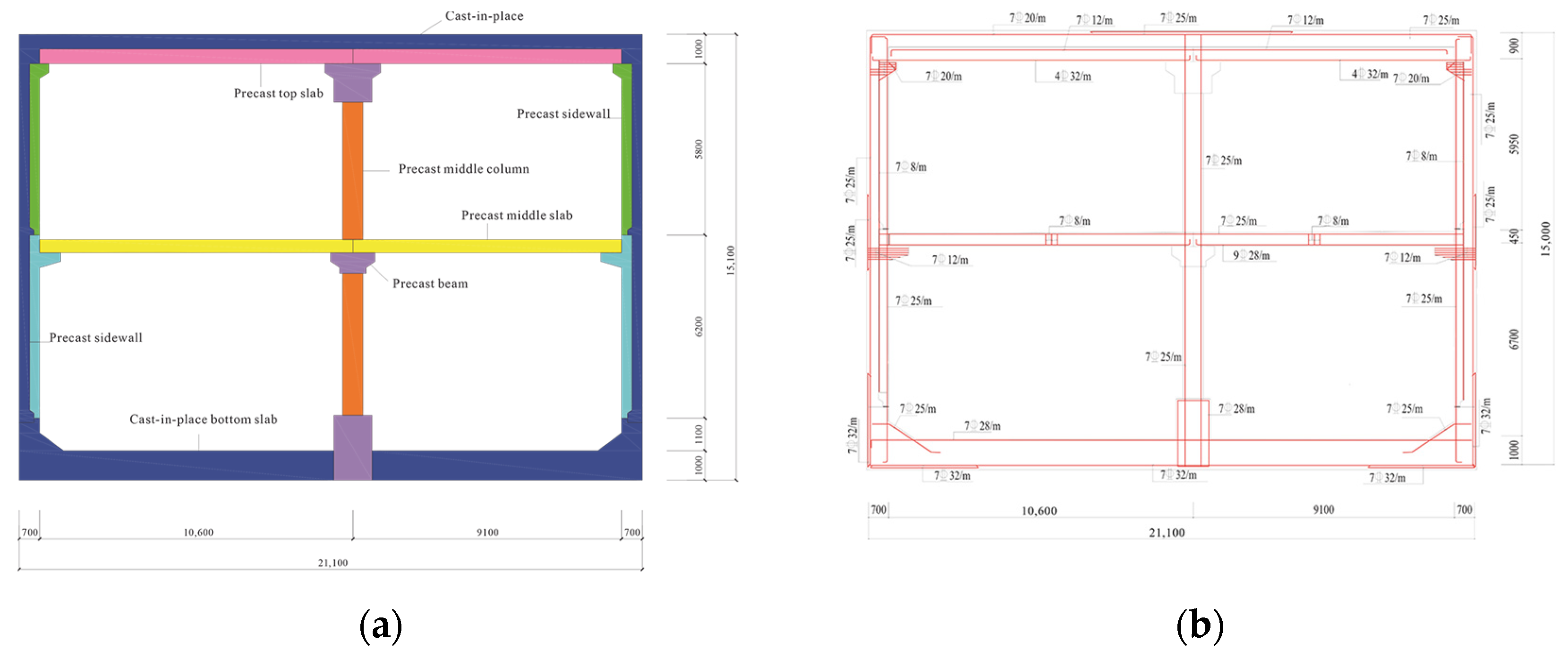
This study is based on the actual engineering design scheme of a subway station on Line 15 of the Shenzhen Metro in Guangdong Province. The station adopts the ASS system, which has typical wet–dry bonding characteristics. The main structure is a reinforced concrete frame system with two floors and two spans, and the plane layout is in an asymmetric form. The total horizontal span is 21.1 m, with a left span width of 11.3 m and a right span width of 9.8 m. The overall structural height is 15.1 m, and the soil thickness above the top slab is 3.5 m.
The ASS structure ingeniously combines the dual advantages of prefabricated assembly technology and cast-in-place concrete technology. The structural system primarily utilizes large prefabricated components manufactured in factories, enabling standardized production, high-precision processing, and rapid on-site installation, which can significantly enhance the construction efficiency and quality controllability. Additionally, the ASS structure significantly improves the self-waterproofing capability, effectively solving the leakage issues caused by improper handling of construction joints in traditional fully assembled stations. The middle column is made of prefabricated reinforced concrete components, with grouting sleeves embedded at the upper and lower ends. The connection between vertical components is achieved through non-shrinkage cement-based grouting material. The middle slab is made of prefabricated concrete, while the sidewalls are made of large prefabricated components with supporting structures, which are used to support the slabs and, together, form the main prefabricated skeleton. The bottom slab is made of cast-in-place concrete. In the horizontal structural system, both the sidewalls and the top slab adopt a composite structure of precast and cast-in-place composite layers; that is, a certain thickness of cast-in-place concrete layer is set on the surface of the prefabricated sidewalls and top slab. In key stress-bearing areas, a cast-in-place concrete post-pouring strip is set up to form a wet connection. All major structural joints in the horizontal direction are connected using two high-strength connection methods, namely, a concrete pouring strip or grouting sleeve connection. In addition, in order to improve the bonding strength of the concrete between prefabricated components, all joint contact surfaces were mechanically chiseled or surface roughened according to the specifications to form a rough interface that meets the standards. Figure 1 shows the typical cross-sectional construction details of the ASS structure, including the geometric dimensions, division of the prefabricated and cast-in-place areas, and the steel bar arrangement scheme.

2.2. Establishment of Finite Element Model

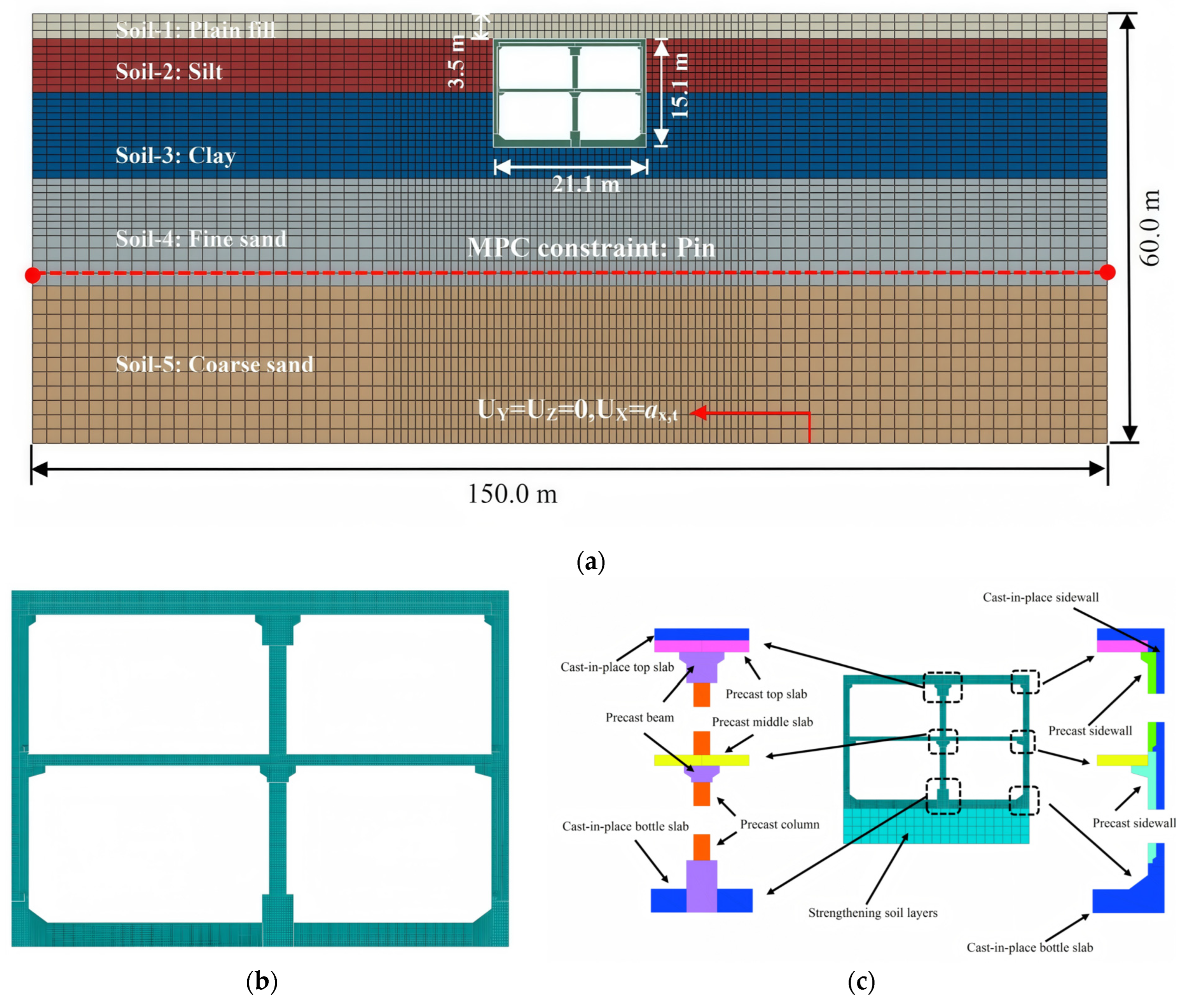
This study used the finite element analysis software ABAQUS 2024 to establish a two-dimensional plane strain finite element model of a rectangular subway station, considering soil–structure interactions, for conducting dynamic time history analysis. To reflect the structural characteristics of prefabricated structures, all prefabricated components in the model were defined as independent geometric parts to simulate the discontinuous mechanical behavior in the joint area in detail. In order to simulate the soil–structure interaction reasonably and minimize the reflection interference of artificial boundaries on seismic wave propagation, the model was fully extended in the horizontal direction. The distance between the left and right boundaries of the structure and the outer edge of the station is not less than three times the total width of the structure [26,27,28]. The overall model has a horizontal span of 150 m, which meets the requirements of far-field boundary conditions. The vertical boundary extends from the surface (upper boundary) to a stable bedrock surface (lower boundary) at a depth of 60 m, fully covering all major soil layers where the subway station is located. Figure 2 shows the finite element numerical model of the soil–structure system used in the dynamic time history analysis.
To ensure both computational accuracy and simulation efficiency, this study employs the CPE4R element, a 4-node plane strain quadrilateral with reduced integration and hourglass control for discretizing the soil and concrete segments. The use of reduced integration effectively mitigates shear locking under large deformations and plastic flow, while the hourglass control ensures numerical stability. This combination makes CPE4R particularly well-suited for capturing complex, inelastic mechanical behaviors and ensures robust convergence in modeling contact nonlinearities such as slip and separation at soil–structure interfaces. As a result, the element accurately represents the dynamic response characteristics during a seismic soil–structure interaction. For slender structural components such as rebars and embedded couplers, the B21 element, a 2-node linear beam element, was adopted. The element effectively simulates axial tension compression, bending stiffness, and the yield and post-yield hardening behavior of reinforcement. To achieve realistic composite action between steel and concrete, the “Embedded Region Constraint” technique was used to embed B21 rebar elements within the CPE4R concrete host elements. This approach automatically enforces displacement compatibility between the two materials, ensuring efficient stress transfer while still permitting controlled relative slip. Consequently, it realistically captures the bond–slip effect, particularly in regions that are prone to cracking and interface degradation. The synergistic use of CPE4R for bulk materials and B21 for embedded reinforcement enables a computationally efficient yet physically accurate simulation of the coupled nonlinear behavior in prefabricated underground structures, including material degradation, interface interaction, and the overall system-level seismic response [29,30].
The size of the soil elements was determined based on the wave propagation criterion proposed by Kuhlemeyer and Lysmer [31]. The criterion requires that the size of the finite element mesh is sufficiently small, such that each wavelength in the wave propagation direction contains at least 8 to 10 elements, thereby ensuring the accuracy of the structural response at the highest analysis frequency. The equation of the criterion can be expressed as
h max 1 8 ~ 1 10 × v s f max
where hmax is the maximum grid size of the element, fmax is the maximum shear frequency of ground motion, and νs is the maximum shear wave velocity.
According to Equation (1), the maximum allowable soil element size was calculated to be 2.42 m. To strike a balance between computational accuracy and solution efficiency, in the key influence areas surrounding the subway station structure and within the soil–structure interaction region, the soil elements were further refined to a grid of 1 m × 1 m. In the lateral and bottom far-field areas that are farther away from the structure, due to the smaller seismic response gradient, the stress wave energy has significantly attenuated, and its impact on computational accuracy is relatively limited. Therefore, the soil element size is gradually transitioned and expanded to 2 m × 2 m. In addition, to ensure the precise capture of the mechanical responses in key structural components, particularly the stress concentration in joint areas, as well as damage evolution behaviors, the finite element mesh size of the structure itself was strictly controlled. The maximum mesh size of the structure was set to 0.1 m. The mesh sensitivity analysis was conducted to ensure the independence of the results from mesh discretization. Comparisons of the maximum inter-story drift ratio and peak bending moment under PGA = 0.4 g excitation showed that further refinement beyond the current mesh density resulted in changes of less than 2.5%, confirming that the selected mesh provides a converged solution.

2.3. Material Properties

The combination of the viscoelastic–plastic model and the Mohr–Coulomb yield criterion is widely used in numerical simulations of geotechnical engineering to accurately describe the complex nonlinear mechanical behavior of soil under static and dynamic action [32,33]. Then, the viscoelastic–plastic model can comprehensively reflect the elastic deformation, plastic yield, strain hardening, and time-dependent viscous effects of soil, effectively determining the yield and failure conditions of soil under complex stress states. The equation of the Rayleigh damping parameter for the soil layer can be described as
ξ i = α + β ω i 2 / 2 ω i
where ξi is the damping ratio, ωi is the natural vibration period, α is the mass damping coefficient, and β is the stiffness damping coefficient.
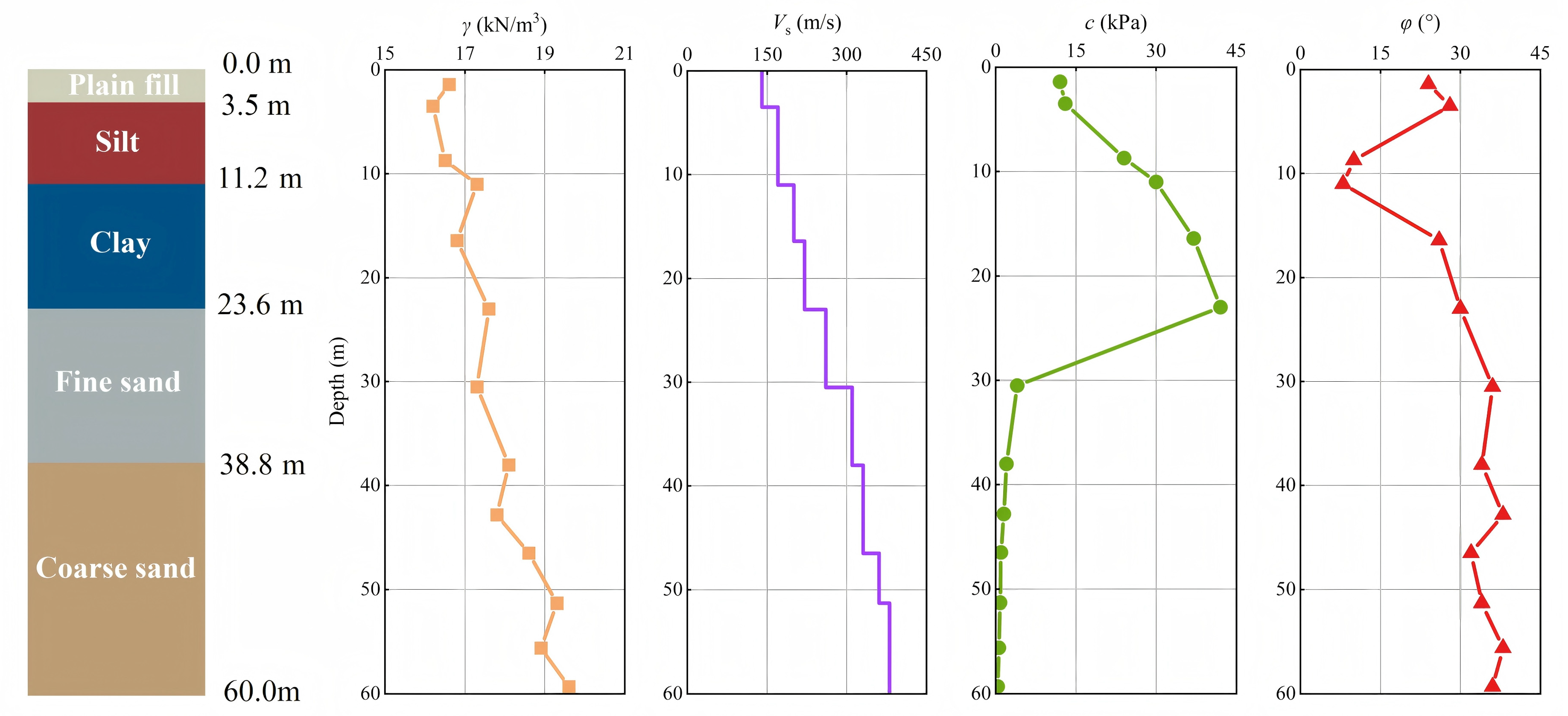
According to geological exploration data, the subway station is located in a typical soft soil site with a complex soil layer distribution, which can be generally divided into five main geological strata. Based on the research results on the mechanical behavior of soft soil in references [28,34], combined with the site geological survey report and relevant engineering experience, the basic physical and mechanical parameters of the soft soil used in this study were finally determined. Figure 3 shows the detailed information on the soil stratum. Where Vs is the shear wave velocity of the soil, γ represents the gravity, c, φ, respectively, represent cohesion and the friction angle.
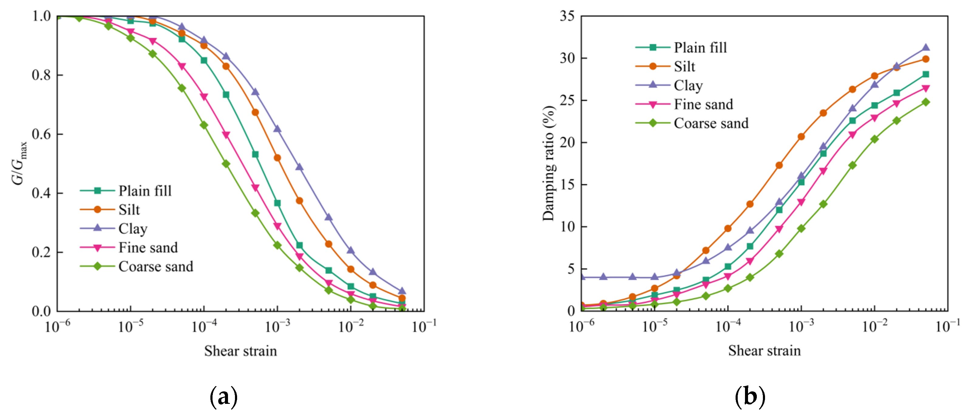
To accurately simulate the nonlinear dynamic response characteristics of soft soil stratums under seismic action, this study used the equivalent linearized seismic response analysis program EERA [35] to conduct a seismic response analysis of a one-dimensional horizontal layered system of soil stratums at the site. By inputting the dynamic time history that conforms to the regional seismic characteristics and considering the strain dependence of the soil, EERA calculated the strain-compatible equivalent shear modulus ratio G/Gmax and equivalent damping ratio. The process is based on the equivalent linearization assumption, iteratively solving until the shear modulus of each element of the soil stratum matches the calculated shear strain phase, thereby obtaining dynamic parameters that are suitable for the actual strain level, effectively reflecting the stiffness degradation and energy dissipation characteristics of the soil under strong earthquakes. On this basis, referring to the recommended equivalent stiffness calculation method in the Federal Highway Administration (FHWA) Seismic Design Guidelines [36], the values obtained from the EERA analysis are reasonably mapped to the soil elements in the two-dimensional finite element model to correct the initial shear modulus of each soil stratum, ensuring that the soil exhibits nonlinear stiffness evolution behavior that is consistent with the actual seismic response in the dynamic analysis. When constructing a two-dimensional soil–structure interaction finite element model, the modified shear modulus is combined with the Mohr–Coulomb elastoplastic constitutive model to describe the nonlinear stress–strain relationship of soil. This model can reasonably capture the stiffness degradation, cumulative plastic deformation, and lateral displacement development of soil during earthquakes. Figure 4 shows typical curves of the shear modulus ratio G/Gmax and damping ratio changes of the soil layers used, which are determined based on field soil sample test data and are referenced to standardized models of typical soils. The soil modeling method, combined with EERA one-dimensional analysis and two-dimensional finite element equivalent parameter input, has been widely validated and successfully applied in multiple seismic studies of underground structures [37,38].
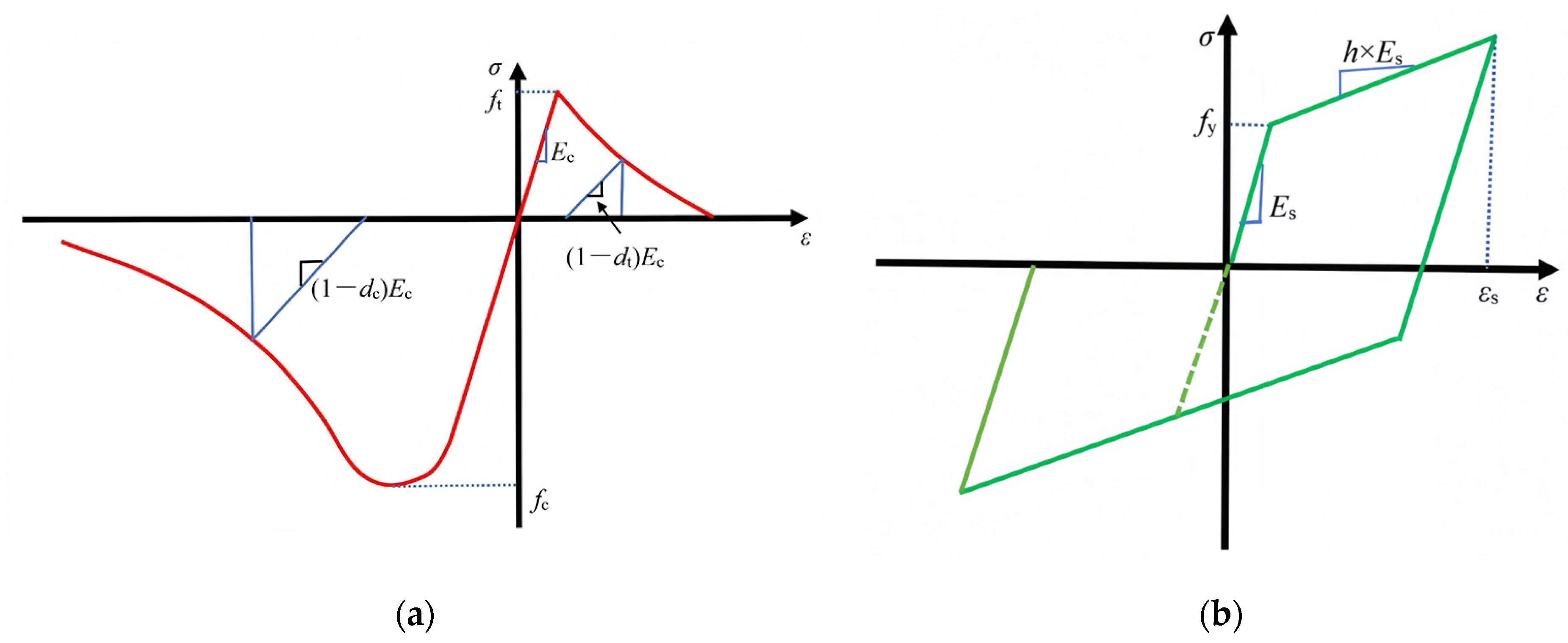
The improved concrete damaged plasticity model (CDP) was employed to describe the nonlinear mechanical behavior of structural components under complex stress states [39,40]. The CDP model, which is based on the work of Lubliner et al. [41], was adopted to simulate the inelastic behavior of concrete under cyclic loading. The model can effectively simulate the stiffness degradation, strength attenuation, and energy dissipation characteristics of concrete during tensile cracking and compressive crushing, making it particularly suitable for structural response analysis under seismic action [42]. The bilinear stress–strain model was used to simulate the steel bar. All components of this study are made of C50, with HRB400 steel bars embedded in concrete units. The material physical characteristic parameters of C50 are presented in Table 1 and Table 2. The elastic modulus Es of the steel bar is 200 GPa, the yield stress fy is 400 Mpa, and the ultimate strain εs is 0.17. To emphasize the initial elastic response characteristics under seismic action, and to streamline the impact of plastic deformation in non-critical areas on the overall analysis, the bolt and sleeve materials adopt the elastic-perfectly plastic model. This model postulates that the material exhibits fully elastic behavior until the stress attains the yield strength, characterized by a linear stress–strain relationship; upon reaching the yield stress, it transitions into the plastic phase, allowing strain to progress further while stress remains constant. The material behavior models adopted for concrete and steel bars are shown in Figure 5.

2.4. Boundary and Contact Settings

To accurately simulate the dynamic response of a soil–structure system under seismic action, this study adopts a two-stage numerical analysis method to systematically realize the entire process from static initial state establishment to a dynamic response solution. In the first stage, static stress balance analysis was carried out by applying normal displacement constraints on the lateral boundaries on both sides of the model, completely fixing the bottom boundary, and only considering the gradual loading of soil and structural self weight so that the system gradually reaches a stable initial stress state; thus, truly reflecting the in situ stress distribution of the site before the earthquake. When entering the second stage of dynamic time history analysis, a dynamic reconstruction of the boundary conditions was carried out to more reasonably simulate the propagation mechanism of the seismic waves. The original horizontal normal constraint has been replaced with a node-to-node multi-point constraint (MPC), set as a “pin”-type connection, allowing boundary nodes to slide freely in the vertical direction while maintaining displacement coordination in the horizontal direction. This MPC technology couples the horizontal displacement of nodes with the same y-coordinate on the left and right boundaries with the corresponding free-field reference nodes, effectively achieving free-field boundary conditions, significantly reducing non-physical reflections of seismic waves on the lateral boundary, and improving the simulation accuracy of wave-field propagation. At the same time, the x-direction degrees of freedom of the bottom boundary are released to allow for the free input of horizontal shear waves. Horizontal seismic motion is in the form of vertically incident shear waves and is applied upwards from the bottom of the model through a specified acceleration time history curve, simulating the physical process of seismic waves propagating from bedrock to the surface. This two-stage analysis method, combined with a reasonable load application path and advanced boundary treatment techniques, has been validated in multiple seismic response studies [43,44,45].
The prefabricated subway station structure is assembled on-site from numerous components prefabricated in the factory, and its overall mechanical performance heavily relies on the force transmission mechanism in the joint area. This transmission mechanism primarily consists of three key components working synergistically. Firstly, it involves the direct transmission of tensile and compressive stress through steel bars that penetrate the joints, exerting the “force transmission rod” effect. Secondly, it utilizes the mechanical interlocking formed by keyways, concave–convex tenons, or shear keys set at the ends of prefabricated components to provide shear bearing capacity—known as the shear key mechanism. Thirdly, the bonding force that is generated between the contact surfaces of the prefabricated components by post-poured high-strength cement-based grouting material or interface mortar effectively transmits shear stress and suppresses interface slip. In numerical simulations, the continuous force transmission of steel bars and the geometric fitting effect of keyway or mortise and tenon structures are accurately reproduced through refined finite element geometric modeling. However, the bonding performance between interfaces is influenced by various factors, and the high uncertainty of interface bonding strength makes the joint area a critical weak link in structural analysis, significantly impacting overall stiffness, deformation coordination, and seismic performance. Therefore, in the analysis, interface properties based on contact algorithms are used for refined characterization.
In finite element analysis, the “pin action” of steel bars and the mechanical shear transfer effect of keyway or mortise and tenon joints are typically achieved by accurately modeling their geometric features in order to capture the local stress transfer mechanism in the joint area. To strike a balance between computational efficiency and engineering practicality, this study employs the “Surface-to-Surface” contact algorithm to simplify the modeling of structural joint interfaces. Furthermore, it sets the most unfavorable bonding state, assuming that relative slip or complete separation may occur between the contact surfaces of prefabricated components. This approach can evaluate the performance degradation trend of the structure under seismic action [46]. In this framework, the normal behavior of the contact surface is defined as “Hard Contact”, allowing the interface to freely separate under tension but maintain contact and transmit pressure under compression. This accurately reflects the extremely low tensile strength characteristic of concrete materials. The tangential behavior is simulated based on the Penalty Method combined with the Coulomb friction model, using a friction coefficient of 0.8 [47]. The starting conditions for relative displacement are controlled by slip tolerance parameters, reasonably reflecting the nonlinear degradation process of the interface’s shear transmission capacity. It should be noted that in actual ASS, due to measures such as post-pouring grouting, interface treatment, and steel reinforcement anchoring, the joint bonding strength is usually higher than that of the idealized model assuming complete slip, but it is lower than the continuous state of complete integral casting. Additionally, to simulate the interaction between soil and a structure, a “surface-to-surface” contact pair is defined between the outer surface of all structures and the surrounding soil, with the soil side designated as the “primary surface” and the structure side as the “secondary surface”, using a friction coefficient of 0.4 [48]. The frictional behavior follows a Coulomb-type yield criterion, consistent with established practices in geotechnical interface modeling [49].

2.5. Selection of Ground Motions

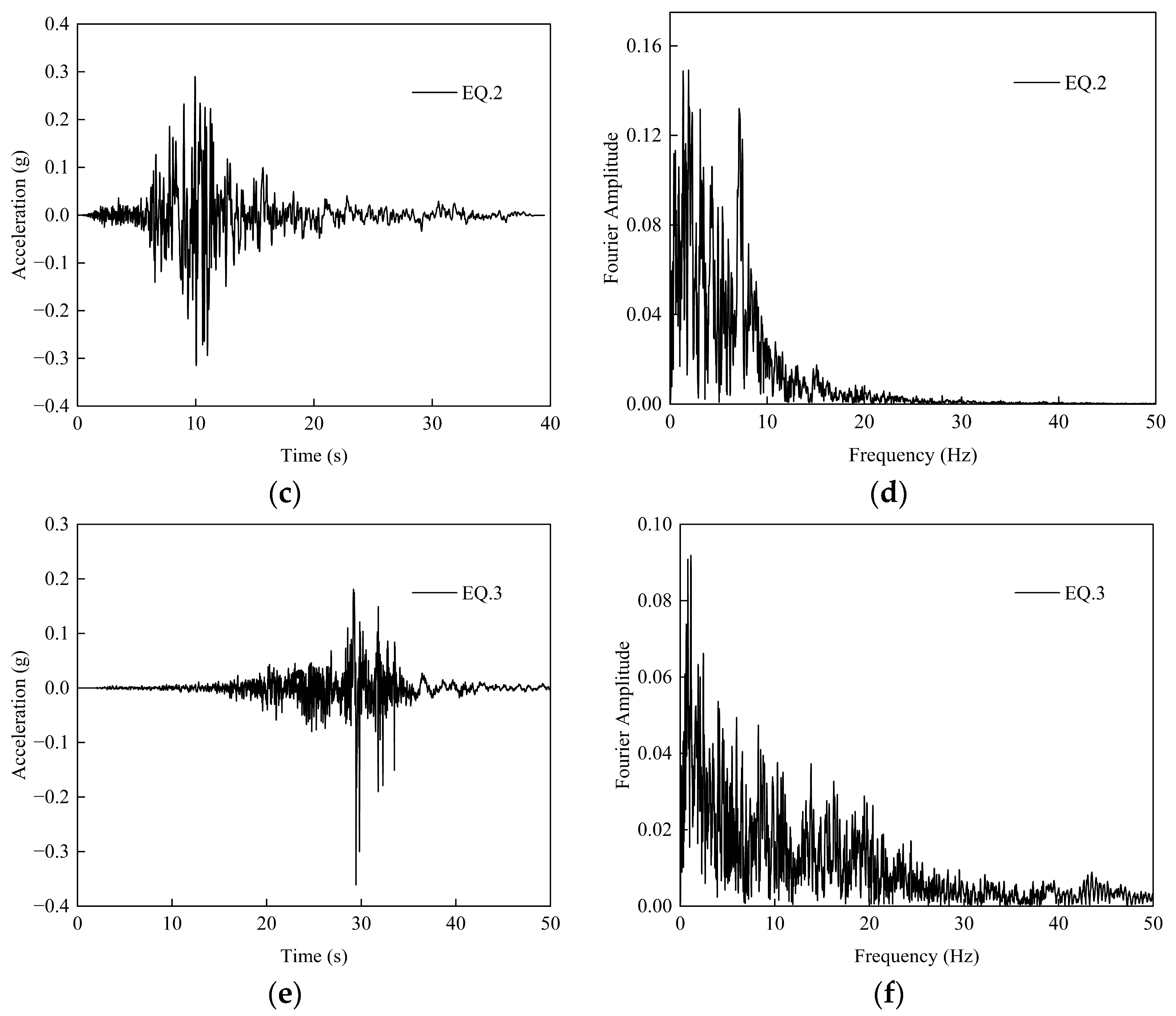
To comprehensively evaluate the dynamic response and seismic performance of an assembly splicing subway station structure under different seismic characteristics, three sets of representative ground motion records were selected from the PEER NGA West 2 database [50]. The seismic records are from the Loma Prieta, Imperial Valley-06, and Chi-Chi earthquake events, each possessing unique spectral characteristics and intensity levels, effectively covering different types of seismic inputs. The detailed information of the three records is represented in Table 3.
Given the pronounced sensitivity of subway station structures to seismic activity, particularly the significant displacement responses that are triggered by velocity pulse effects and high-frequency energy concentration, the three sets of seismic records chosen in this study are all representative of typical characteristics and high peak ground velocities (PGV), effectively simulating the nonlinear dynamic behavior of underground structures during intense earthquakes. To systematically study the seismic response of structures under varying earthquake intensities, the peak ground acceleration (PGA) of all seismic motions was uniformly adjusted to four levels: 0.1 g, 0.2 g, 0.3 g, and 0.4 g, each corresponding to a distinct level of seismic intensity.
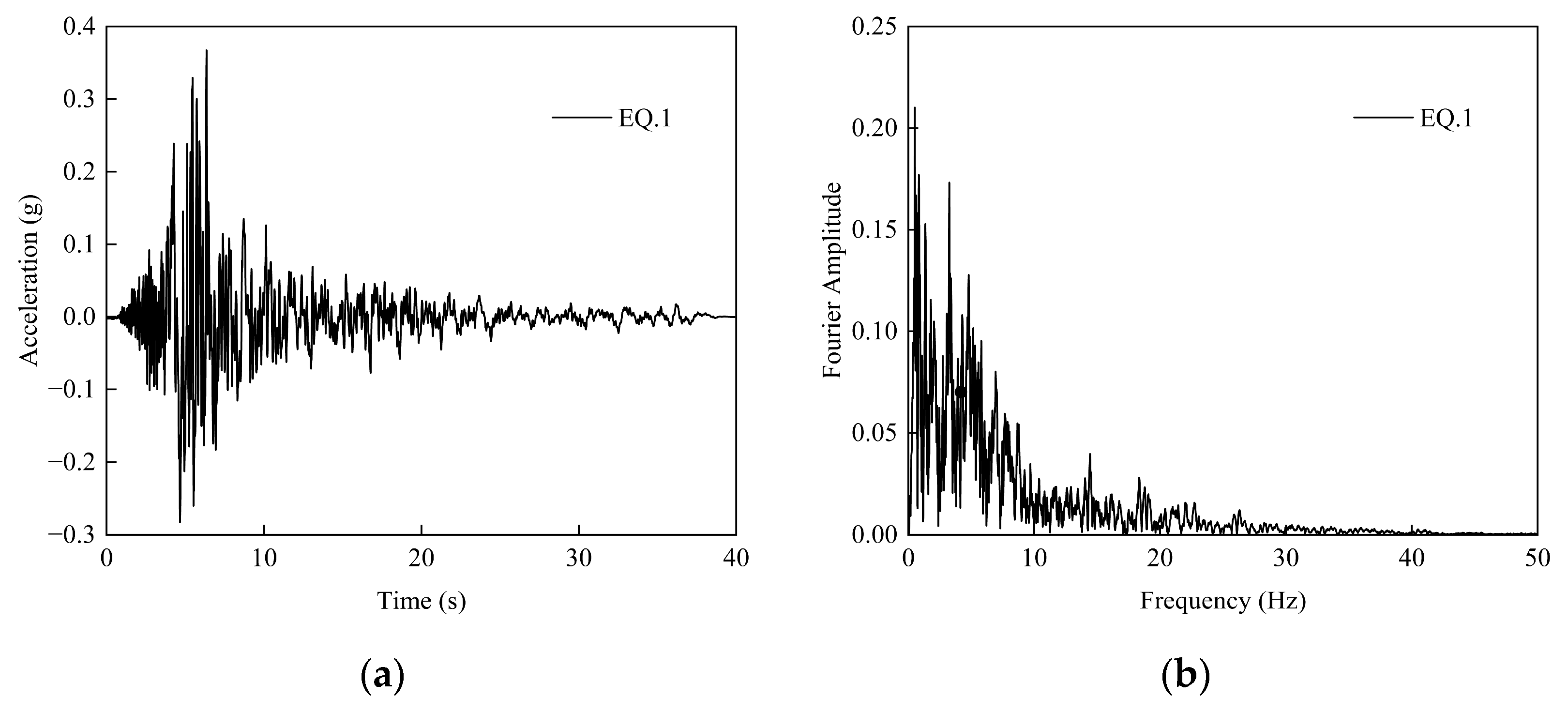
The vibration frequency characteristics can be indirectly reflected by obtaining the ratio of PGA to PGV [51]. When the ratio of PGA to PGV is greater than 1.2, ground motions are classified as high-frequency earthquake motion; When the ratio of PGA to PGV is between 0.8 and 1.2, ground motions are defined as intermediate-frequency ground motions. When the ratio of PGA to PGV is less than 0.8, ground motions are considered as low-frequency ground motions. By calculation, the PGA/PGV of EQ.1 is equal to 0.75, the PGA/PGV of EQ.2 is equal to 1.01, and the PGA/PGV of EQ.3 is equal to 1.67. The selected input ground motions in this work have low-, medium-, and high-frequency vibration characteristics, respectively. Figure 6 presents the vibration characteristics under three ground motion records.
To assess the influence of the frequency characteristics of the selected ground motions on structural response, the PGA/PGV ratio for each record was calculated—a commonly used indicator of the dominant period or frequency content of ground motions. The analysis reveals that, even at the same PGA, structural responses vary significantly across different ground motions, primarily due to the differences in the frequency content. For instance, ground motions with higher PGA/PGV ratios are more likely to excite higher-order modes of the structure, leading to concentrated responses in the upper portions. In contrast, ground motions with lower PGA/PGV ratios may induce more uniform or deeper responses, particularly posing greater risks to long-period structures. This indicates that a structural seismic response depends not only on the magnitude of PGA but is also strongly influenced by the spectral characteristics of the ground motion. Furthermore, by scaling the motions across multiple PGA levels, the complete evolution path of the structure from elastic behavior to nonlinearity and progressive damage accumulation can be clearly identified. The IDA approach, based on multiple real seismic records, effectively reduces the potential bias arising from using a single or a few artificial waves, thereby enhancing the robustness and reliability of the conclusions.

3. Seismic Response Analysis

3.1. Interlaminar Drift Ratio of Station Structure

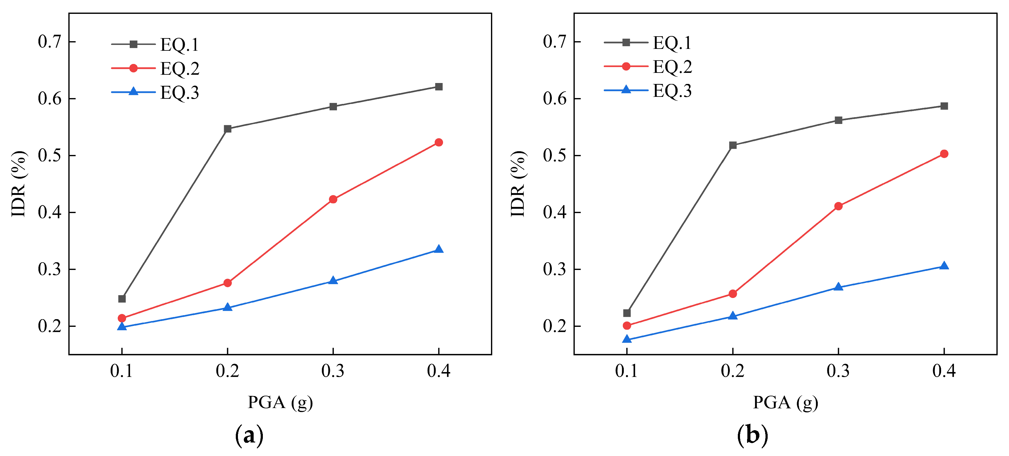
The interlaminar drift ratio (IDR) is a key indicator for evaluating the seismic response of underground structures, especially for complex and highly integrated underground structures such as prefabricated subway stations. Table 4 and Figure 7 present the IDR for the assembly splicing structure with a PGA under different ground motions. The ratio of relative displacement in the horizontal direction to floor height can be expressed as
I D R = u 2 u 1 h c
where u1 is the displacement of the lower floor, u2 is the displacement of the upper floor, and hc is the floor height.
As can be seen from Table 4, the IDR of the upper floor is significantly greater than that of the lower floor. For the record EQ.1, as the PGA increases from 0.1 g to 0.2 g, both the upper and lower floors show a significant increase in IDR, but the increase is more pronounced in the upper floor. When the PGA is 0.1 g, the IDR of the upper floor is 0.248%, while that of the lower floor is 0.223%. When the PGA increases to 0.2 g, the IDR of the upper floor rapidly rises to 0.547%, while that of the lower floor is 0.518%. This indicates that under the record EQ.1 with significant low-frequency motion characteristics, the upper layer of the station structure is more sensitive to seismic response, exhibiting greater deformation. Furthermore, as the PGA continues to increase to 0.3 g and 0.4 g, although the IDRs of both the upper and lower floors still maintain a growth trend, the growth rate has slowed down, indicating that the structure has entered a nonlinear response phase. At this point, there may be local damage formation within the structure, leading to stiffness degradation and deformation concentration. It is worth noting that under the seismic records of EQ.2 and EQ.3, although the IDR of the upper floor is still higher than that of the lower floor, the overall values are relatively low, and the trend of change with the PGA is relatively smooth. This is mainly due to the fact that seismic ground motions dominated by mid-to-high-frequency components have a relatively weak impact on shallow-buried structures in soft soil, making it difficult to induce significant resonance effects and large deformation responses.
In Figure 7, it can be seen that the IDR of the ASS structure varies significantly with different ground motion records. When subjected to seismic input with low-frequency vibration characteristics (EQ.1), the IDR of the structure is considerably greater than that under inputs of medium-frequency (EQ.2) and high-frequency (EQ.3) seismic motion, and exhibits obvious nonlinear characteristics. In contrast, seismic input with high-frequency motion (EQ.3) results in the smallest IDR. This indicates that shallow-buried structures in soft soil exhibit higher sensitivity to seismic motions with low-frequency characteristics. It is mainly due to the low shear wave velocity and long dominant period of soft soil, which are prone to resonating with low-frequency seismic motions, thereby amplifying the dynamic response and leading to significant deformation response, increasing the risk of structural damage. In addition, due to the attenuation characteristics of soil layers to high-frequency motions, the energy inputs from EQ.2 and EQ.3 are weaker, resulting in relatively smaller structural responses. The phenomenon reveals that the matching relationship between site characteristics and seismic input is crucial for structural safety assessment, especially in soft soil. In the design process of underground structures, particular attention should be given to the impact of low-frequency seismic input to ensure the overall stability and safety.
It is worth noting that ground motions with different frequency components correspond to different dominant failure modes. Low-frequency seismic motion is prone to inducing large overall deformations, and an isolation design should be adopted to extend the period. Medium-frequency seismic motion can lead to local stress concentration, and local resistance should be enhanced through joint reinforcement and additional energy dissipation devices. For high-frequency seismic motion, attention should be paid to acceleration response, and it is recommended to use high-damping materials to suppress vibration transmission. Therefore, in the design of prefabricated subway stations, a targeted selection of seismic isolation or mitigation systems or local reinforcement schemes should be made based on the results of site seismic hazard analysis.

3.2. Analysis of Tensile Damage

According to the analysis results in the previous section, compared with the other two types of seismic records with medium-to-high-frequency characteristics (EQ.2 and EQ.3), when the seismic record EQ.1 with significant low-frequency characteristics is input, the IDR reaches the maximum, and exhibits a significant nonlinear growth trend with the increase in PGA. This indicates that under soft soil conditions, low-frequency seismic waves are more prone to resonate with the natural frequencies of the structure–soil system, leading to more severe overall deformation and local responses, significantly increasing the seismic action on the structure. Based on existing research results, under seismic action, subway station structures primarily bear tensile stress concentration and shear deformation, while the compressive damage to concrete materials is usually not significant. The failure modes more often manifest as tensile cracking, as well as opening and sliding in joint areas [52]. The tensile damage condition caused by low-frequency seismic motion has emerged as the most unfavorable scenario for studying the seismic response of an underground structure.
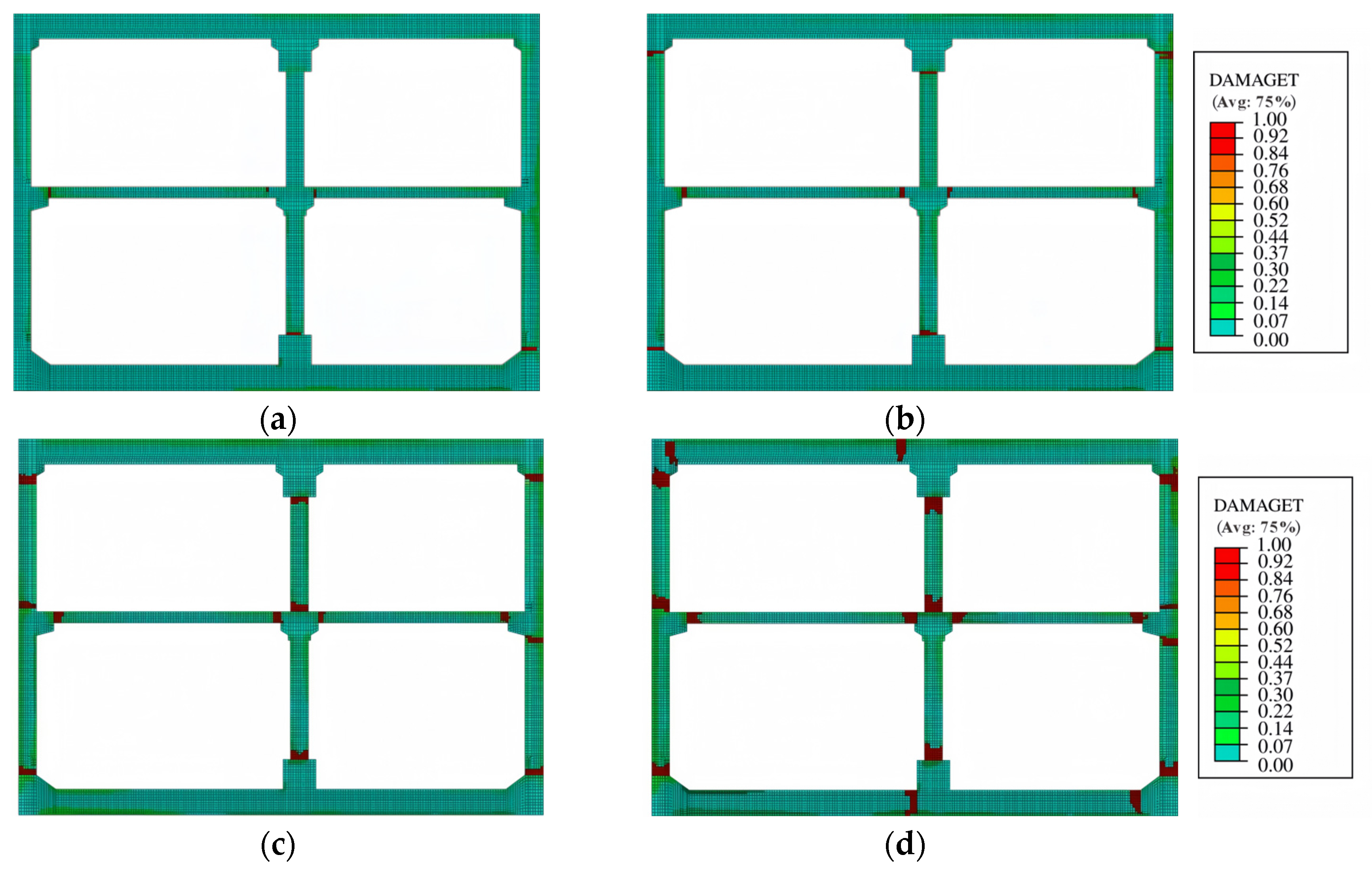
Based on the aforementioned analysis, this study selected the most representative low-frequency ground motion record EQ.1 as the input to further systematically investigate the tensile damage evolution law of the assembled and spliced structure under different earthquake intensities. Figure 8 shows the distribution of the tensile damage (DAMAGET) contour map of the structure under four conditions with a PGA of 0.1 g, 0.2 g, 0.3 g, and 0.4 g, respectively. DAMAGET is the tensile damage variable in the concrete damage model, with a value ranging from 0 to 1. When DAMAGET = 0, the material is in an elastic state and has no damage. As DAMAGET approaches 1, it signifies that the concrete has entered a highly cracked state, approaching complete loss of tensile-bearing capacity, tending towards tensile failure.
From Figure 8, it can be found that as the PGA gradually increases, the damage to the assembly splicing subway station structure exhibits a development trend of gradual evolution from local to overall, and from minor to severe. The initial damage is mostly concentrated in key connection joints of the structure. Subsequently, under strong seismic action, the damage continuously expands and penetrates, eventually forming local failure paths that affect the overall stability.
When PGA = 0.1 g, the structure remains in the minor damage phase. The primary damage manifests as initial damage at the joint between the middle slab and the sidewalls, resulting from concentrated longitudinal shear stress and localized concrete compression damage at the bottom of the middle column due to strong constraints. As the seismic intensity escalates to 0.2 g, the structure transitions into the moderate damage phase. The nonlinear behavior of the connecting joints intensifies, and noticeable tensile damage begins to emerge at the seam between the middle column and slab. Additionally, due to the asymmetric span of the middle slab leading to internal force redistribution, the damage in the left connection area becomes more pronounced, highlighting the detrimental impact of geometric asymmetry on structural response. When the PGA reaches 0.3 g, structural damage intensifies further. The joint between the upper sidewall and the top slab, which bears the primary function of transmitting horizontal forces, undergoes shear slippage and damage under the combined action of shear and bending moments, indicating the degradation of a key force transmission path. Simultaneously, damage also begins to appear at the joint between the middle column and each slab, indicating that the structural damage has spread from a localized area to multiple key parts. When PGA = 0.4 g, the damage range significantly expands, and damage at the joint of the upper left corner bracket and the sidewall extends upwards, forming a potential corner failure mechanism. The connection area between the upper end of the middle column and the top slab experiences tensile damage and detachment, and the damage to the bottom slab joints continues to develop, with local areas nearing complete damage. At this point, the structure is nearing failure, with the collaborative working ability of multiple key joints severely weakened, and the integrity and ductility significantly reduced.
Moreover, the damage evolution process demonstrates a very high degree of consistency with the typical seismic damage patterns and failure mechanisms of underground structures reported in reference [22]. The numerical model accurately captures the observed characteristic failure sequences, such as initial cracking at critical joints, progressive damage accumulation in the sidewalls and splicing interfaces, and the final development of dominant failure planes. The strong qualitative and phenomenological agreement is not merely coincidental. It serves as a robust form of indirect validation, demonstrating that the model is capable of reproducing the fundamental physical mechanisms governing the seismic response of underground structures. These complex nonlinear failure modes arise from the intricate interaction between soil nonlinearity, structural material degradation, and interface contact behavior. This consistency significantly enhances confidence in the model’s ability to simulate real structural behavior under seismic loading, thereby ensuring the credibility and scientific value of the findings presented in this study.
It is worth noting that in the seismic design of assembly splicing subway stations, great importance must be attached to the design and reinforcement of key joints and connecting components. These parts are not only the components for force transmission but also the areas where damage first occurs and concentrates. The performance directly determines the overall seismic resistance of the structure. This study reveals the evolutionary law of prefabricated subway stations, which progresses from local damage at joints to overall failure, providing a scientific basis for establishing multi-level seismic performance objectives. It is recommended to introduce graded performance verification for weak links, such as critical joints in the design standards, and clarify specific control indicators for multi-level seismic performance objectives.

3.3. Response of Splicing Interface

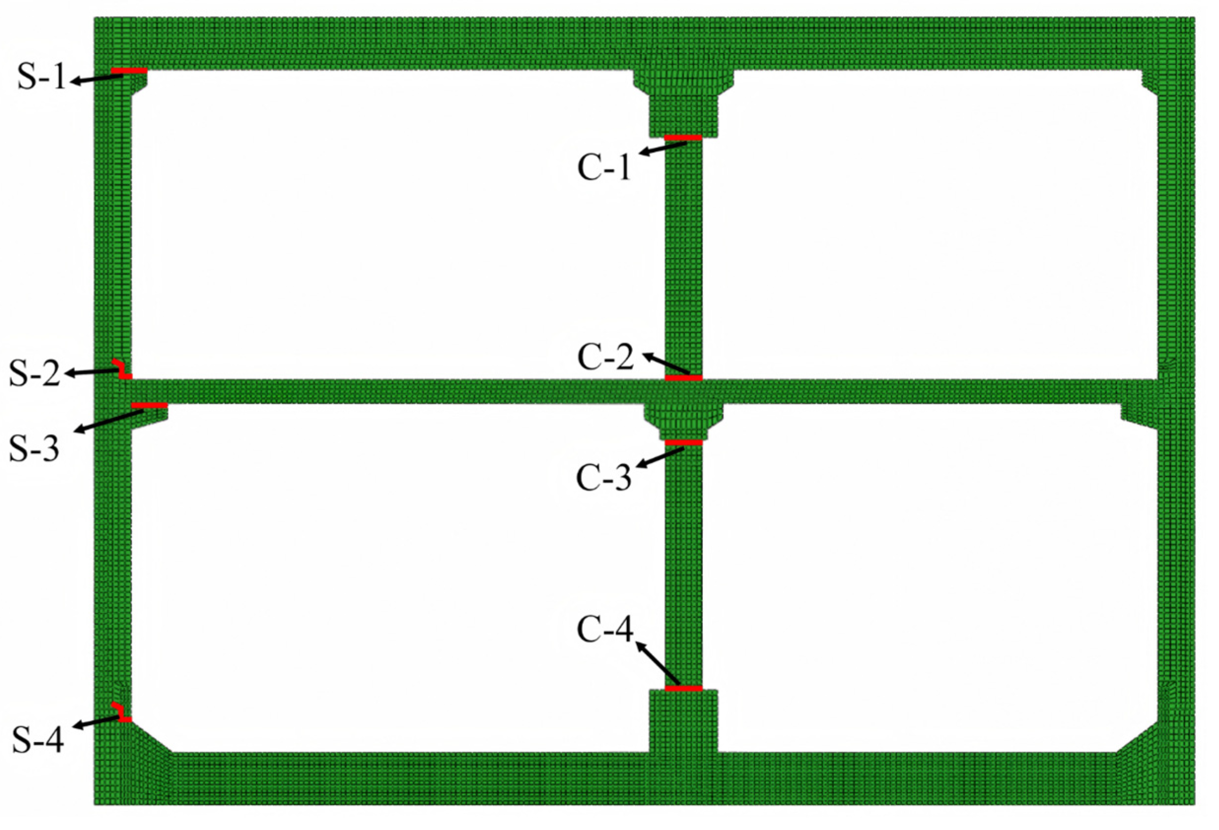
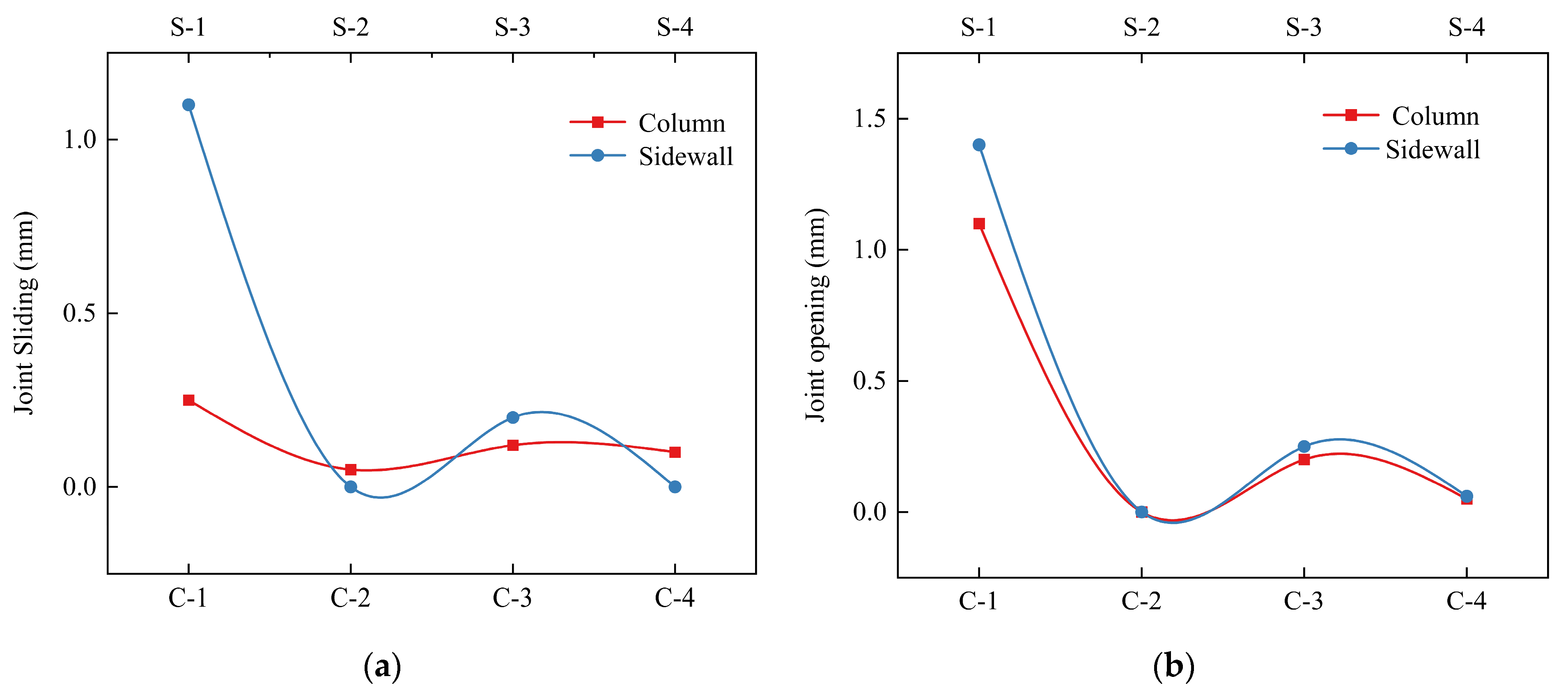
To evaluate the connection performance of the splicing interface, multiple sets of displacement monitoring sections were systematically arranged at key structural stress-bearing locations such as the sidewall (S), middle column (C), bracket areas where the top slab meets the sidewall, bottom slab connection areas, and critical splicing joints, as shown in Figure 9. The monitoring sections are primarily located at interface positions where significant horizontal sliding or vertical opening may occur in order to comprehensively record the dynamic evolution process of the horizontal relative sliding distance and vertical opening width of each key section.
Figure 10 illustrates the distribution characteristics of the maximum horizontal sliding distance and vertical opening width of the assembly splicing subway station structure obtained through finite element analysis at various key monitoring sections when the PGA = 0.4 g. As can be seen from Figure 10a, the horizontal relative sliding distance at the top of the sidewall (S-1) is significantly higher than that of the other parts, with a maximum value exceeding 1.0 mm, which is clearly the highest among all monitoring sections. The results indicate that under strong seismic action, the top of the sidewall bears the large bending moment and shear force. Due to the weak boundary constraints, it is prone to producing large lateral displacement responses. This area is the splicing location of prefabricated wall, and the rigidity and integrity of the joints are reduced compared to the cast-in-place structures, leading to cumulative slippage and exhibiting obvious characteristics of a flexible joint. In comparison, the horizontal sliding distance of the top of the middle column (C-1) is only 0.26 mm, which is much smaller than that of the top of the sidewall, indicating that the connection joint between the middle column and the top slab has higher connection stiffness and stronger lateral resistance. This is mainly due to the superior integrity and restraint conditions of the middle column compared to the joints of the sidewall, which can effectively transmit horizontal shear forces and maintain the stability of the vertical load-bearing system of the structure. In addition, the horizontal sliding distances in other monitoring sections are all controlled within 0.25 mm, and some areas even approach zero, indicating that the splicing interfaces in these areas have achieved good splicing performance in design and construction, with excellent deformation coordination and no obvious sliding phenomenon. Further analysis reveals that the differentiated slip distribution reveals the non-uniform stress characteristics and the concentration of weak links of the structure under strong earthquakes. As one of the main horizontal force resisting components, the top of the sidewall, with excessive slip, may lead to seal failure of joints, damage to the waterproof layer, and even affect the supporting stability of the top slab. It is a key control part for the seismic performance of the structure. The smaller slip in the middle column and other areas indicates that the splicing interface still maintains good integrity. By combining the distribution of joint opening widths in Figure 10b, it can be further observed that not only is there significant horizontal sliding at the top of the sidewall, but its joint opening is also relatively large. Therefore, in seismic design, structural measures in the part should be specifically strengthened to enhance the deformation adaptability and long-term durability.

4. Impact of Splicing Interface on the Seismic Response

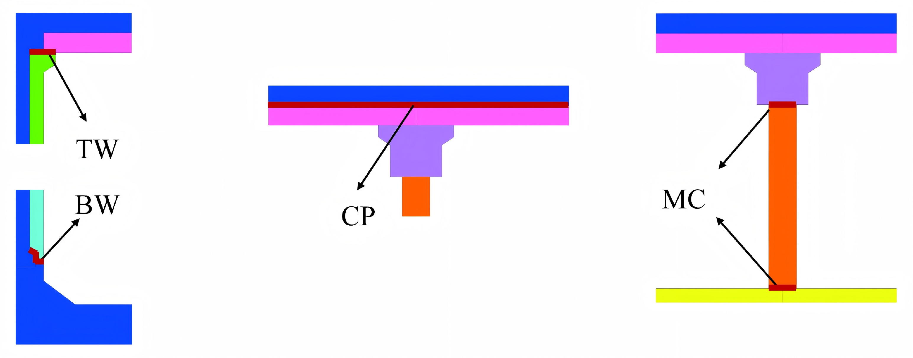
The splicing interface, as a crucial connecting part among assembly splicing structural components, is a core link in the structural force transfer path. To deeply reveal the impact of the splicing interface on the seismic response of the structure, this study adopts two types of contact settings, namely “Surface-to-Surface contact” and “Tie contact”, to simulate the actual mechanical behavior of the splicing interface. This study systematically controls the contact characteristics of component splicing interfaces and deeply explores the mechanism of how splicing interfaces affect the overall interlayer deformation mode and internal force distribution of underground structures under seismic action, as shown in Figure 11. Where TW represents the splicing interface at the top of the sidewall, BW represents the splicing interface at the bottom of the sidewall. CP represents the splicing interface between cast-in-place and prefabricated components, and MC represents the splicing interface at the end of the column. Six different contact setting methods for splicing interfaces were introduced into the numerical model, comprehensively considering various typical working conditions of nonlinear contact when PGA = 0.4 g. The results are listed in Table 5. Where T-interface represents the case that the contact form of the component splicing interface at a certain location is set to “Tie contact”; “T” represents “Tie contact”; “S” represents “Surface-to-Surface contact”, and “A” represents all splicing interfaces. Additionally, u is the interlayer displacement, and η is the ratio of the IDR of each case to the IDR of the T-A case.
As can be seen from Table 5, the splicing interface between the cast-in-place component and the prefabricated component exerts the most pronounced influence on the inter-story drift of the underground structure, and is the key factor controlling the overall deformation behavior. The second most influential interface is the splicing interface at the joint area between the top of the sidewall and the top slab, whose connection performance also has a significant impact on the displacement response of the structure. If the bonding strength of the two interfaces is insufficient, sliding and opening at the joints are prone to occur, leading to a decrease in the overall structural rigidity, a significant increase in inter-story drift, and even localized deformation concentration, weakening the seismic stability of the structure. In contrast, the bond strength of the splicing interface at the end of the central column has a relatively small impact on inter-story drift and can be regarded as a non-sensitive factor. This indicates that although the central column bears the main vertical load, changes in its joint rigidity have limited regulatory effects on overall horizontal deformation. However, it is worth noting that when the splicing interface between the bottom of the side wall and the floor slab adopts a “Tie Contact” setting, the inter-story drift of the structure is significantly reduced. This indicates that a good connection in this area can effectively enhance lateral restraint, improve the integrity and collaborative deformation capacity of the structural bottom, and thus improve the overall seismic performance.
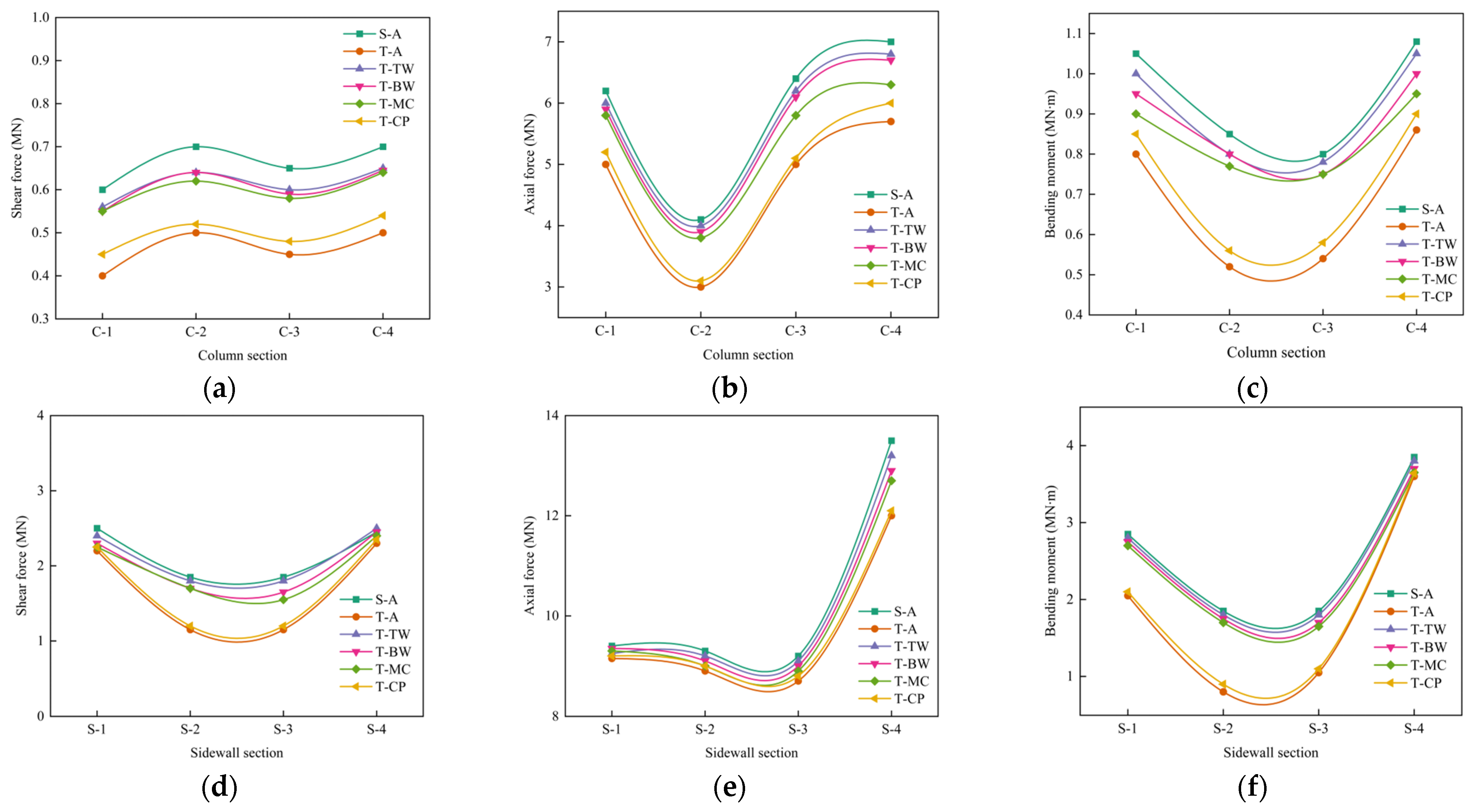
Figure 12 shows the comparative results of the maximum internal force response of the middle column and two sidewalls under six different joint-splicing interface cases when PGA = 0.4 g. From Figure 12, it can be seen that the T-CP case with CP joint rigid connection exhibits the lowest internal force level, which is very close to the T-A case. Both are at the lower limit of the internal force response range of all cases, indicating that achieving high-quality rigid connection of CP between cast-in-place and prefabricated components can significantly enhance the overall integrity and continuity of the structure, optimize the load transmission path, effectively suppress stress concentration in key components, and thus improve the collaborative working ability and mechanical stability of the structure under seismic action. In contrast, the internal force response curves of the T-TW, T-BW, and T-MC cases almost coincide with the S-A case and are all within the upper limit range of internal force response. This phenomenon indicates that although the rigid connection assumption is adopted at the splicing interfaces, such as TW, BW, and MC, its improvement effect on the redistribution of internal force for the overall structure is very limited, and, thus, it is difficult to significantly reduce the stress level of key parts. Further analysis shows that the CP interface between the cast-in-place and prefabricated components is the key control area that determines the seismic performance of prefabricated subway stations. If the interface connection is weak, it is highly likely to form a weak hinge under strong earthquakes, causing an imbalance in the redistribution of internal force, and even inducing shear slip or bending yield, leading to local failure expanding towards overall instability.
5. Conclusions

This study investigates the seismic response of an asymmetric rectangular ASS structure in soft soil. The detailed nonlinear static-dynamic coupled finite element model is constructed, considering the interaction between soil and the structure. By conducting nonlinear incremental dynamic analysis using three different frequency characteristics of seismic records, the influence of seismic frequency on the dynamic response of the structure is analyzed. Based on the seismic records that cause the most unfavorable structural response, the damage distribution of the structure during an earthquake and the mechanical behavior of the splicing interface are evaluated. The influence of the characteristics of the splicing interface on the deformation and internal force of the structure is studied. The following conclusions were obtained:
(1)
Under low-frequency seismic motion, the IDR of the asymmetric rectangular assembly splicing subway station in soft soil increases significantly, with the upper layer response being particularly prominent. However, the structural response, induced by medium-to-high-frequency seismic motion, is relatively small. Soft soil has low shear wave velocity and a long dominant period, which is prone to resonance with low-frequency seismic motion, resulting in significant dynamic amplification effects. The seismic response of the structure is not only influenced by the frequency characteristics of seismic motion and the location, but more crucially depends on the matching relationship between seismic motion and the characteristics of the site soil layer. The coupling effect is the core factor in evaluating and controlling the seismic performance of the structure.
(2)
As the PGA increases, the damage to the assembly splicing subway station structure gradually intensifies, primarily concentrated in the joint areas, manifesting as significant development and accumulation of tensile damage. The damage originates from key connection joints and gradually extends to the intersection areas of the slab and column, forming local failure paths. When the PGA reaches 0.4 g, severe damage occurs at the top of the sidewall, the end of the middle column, and the joints at the corners, leading to a significant degradation in the structural integrity and the tendency towards failure. The connection performance of key joints is the core factor determining the overall seismic performance of the structure, and its structural design and reinforcement measures should be prioritized in the seismic optimization. It is noteworthy that the damage transfer path observed in this study essentially originates from the abrupt change in stiffness and stress concentration that is caused by the discrete connections between prefabricated components. This failure mechanism is determined by the inherent structural characteristics of prefabricated structures and exhibits strong universality. It is relatively insensitive to changes in structural geometric dimensions and foundation parameters, and can, therefore, be regarded as a common failure mode for similar prefabricated underground structures. It should be given significant attention in engineering design.
(3)
The joint area of the assembly splicing subway station exhibits significant non-uniform deformation characteristics under strong seismic action. When the PGA is 0.4 g, the horizontal sliding distance of the top of the sidewall exceeds 1.0 mm, accompanied by a large vertical opening, making it the most prominent weak spot for horizontal sliding and opening. This reflects the obvious flexible connection characteristics of this area due to weak boundary constraints and low joint stiffness, which are prone to seal failure and structural instability. In contrast, the top of the middle column only slides by 0.26 mm, and other areas are controlled within 0.25 mm, indicating that the central column and most splicing interfaces have good connection stiffness and deformation compatibility.
(4)
The contact performance of different splicing interfaces has a significant impact on the distribution of internal forces within the structure. The internal force response of the cast-in-place component and prefabricated component splicing interfaces is close to the lower limit level of the contact setting condition, indicating that the weakening of the connection state of this interface significantly reduces the overall rigidity of the structure, triggers internal force redistribution, and diminishes the efficiency of internal force transfer. However, for splicing interfaces such as the bottom of the sidewall and the ends of the middle column—even if the connection performance changes—the internal forces remain comparable to those of the monolithic structure’s contact setting, maintaining at the upper limit level. In the assembly splicing subway station, the cast-in-place and prefabricated joint area is a key part that controls the overall mechanical behavior, and its connection quality directly determines the structural rigidity characteristics and internal force distribution pattern.
(5)
The frequency characteristics of ground motion significantly affect the dynamic response mode and damage development mechanism of prefabricated subway stations. Therefore, in engineering design, differentiated seismic resistance strategies should be adopted based on the dominant ground motion characteristics of the site. In soft soil sites dominated by low-frequency seismic motion, the structure is prone to large deformations in the upper part and joint slippage. It is recommended to adopt flexible joint designs or set up base isolation layers while enhancing the ductile reinforcement of the upper structure to improve the overall deformation coordination ability. Under medium-frequency seismic motion, stress concentrates on key components such as central columns and side walls, as well as their connection areas. It is advisable to strengthen the joint connection performance by adding shear keys or steel sleeves to enhance its shear bearing capacity and crack control ability. For high-frequency seismic motion, although the overall displacement is small, the acceleration response is intense. Priority should be given to using energy-dissipating bearings to suppress high-frequency vibration transmission, and elastic buffer layers should be set up at the joint locations to protect the waterproof system. In addition, to address the redistribution of internal forces caused by the geometric asymmetry of the structure, reinforcement should be appropriately strengthened in stress concentration areas to enhance local resistance.
This study is based on the typical soft soil site in Shenzhen and the specific ASS section. However, the identified damage initiation locations, evolution paths, and dominant failure mechanisms arise from the inherent characteristics of prefabricated jointed structures and are expected to be broadly applicable to similarly configured ASS systems. Building upon the validated numerical framework developed in this work, future research will systematically extend the analysis to a wider range of geological conditions, structural configurations, and joint detailing. Furthermore, the framework will be expanded to incorporate a more comprehensive set of near-fault ground motions with diverse fault mechanisms and rupture directivity. Future studies could incorporate probabilistic methods and stochastic simulations to quantify the effect of material variability, construction tolerances, and uncertain ground motions on the internal force response and performance of splicing interfaces. This integrated approach will enable a more robust assessment of how seismic source characteristics influence structural demand, ultimately contributing to the development of more universally applicable and refined performance-based seismic design criteria for prefabricated underground structures.

Author Contributions

Conceptualization, K.W.; methodology, K.W., T.Z. and X.C.; software, X.Z. and S.Z.; validation, K.W., T.Z. and X.C.; formal analysis, S.Z. and T.D.; investigation, X.Z.; resources, T.Z.; data curation, K.W.; writing—original draft preparation, K.W., T.Z. and T.D.; writing—review and editing, S.Z. and T.D.; visualization, X.C. and X.Z.; supervision, T.Z.; project administration, T.D. All authors have read and agreed to the published version of the manuscript.

Funding

This research was funded by the Guangdong Provincial Department of Housing and Urban Rural Development Science and Technology Innovation Plan Project (Grant Nos. 2021-K35-301789 and 2023-K47-255536).

Data Availability Statement

The authors confirm that the data supporting the findings of this study are available within the article.

Acknowledgments

The authors would like to thank Ming Zhang from the School of Engineering and Technology, China University of Geosciences, Beijing, for her valuable supervision and support in project administration during the realization of this research.

Conflicts of Interest

Authors Kai Wang, Xun Cheng, and Xiaolin Zhu were employed by the company Sinohydro Bureau 7 Co., Ltd. Authors Tongwei Zhang and Shudong Zhou were employed by the company Dongguan Institute of Building Research Co., Ltd. The remaining authors declare that the research was conducted in the absence of any commercial or financial relationships that could be construed as a potential conflict of interest.

References

  1. Dong, Y.H.; Jaillon, L.; Chu, P.; Poon, C.S. Comparing carbon emissions of precast and cast-in-situ construction methods—A case study of high-rise private building. Constr. Build. Mater. 2015, 99, 39–53. [Google Scholar] [CrossRef]
  2. Jiang, J.W.; Tao, R.; El Naggar, M.H.; Liu, H.; Du, X. Seismic performance and vulnerability analysis for bifurcated tunnels in soft soil. Comput. Geotech. 2024, 167, 106065. [Google Scholar] [CrossRef]
  3. Cheng, X.L.; Li, Q.Q.; Hai, R.; Guo, S.S.; Xing, X.F. Research progress and prospects of seismic performance on underground structure embedded in soft soil foundation. Sci. Rep. 2024, 14, 21883. [Google Scholar] [CrossRef]
  4. Lin, F.; Yang, X.R. Mechanical properties analysis of joints for prefabricated metro station structure based on whole-process in-situ monitoring. Tunn. Undergr. Space Technol. 2023, 138, 105202. [Google Scholar] [CrossRef]
  5. Tao, L.J.; Ding, P.; Shi, C.; Wu, X.W.; Wu, S.; Li, S.C. Shaking table test on seismic response characteristics of prefabricated subway station structure. Tunn. Undergr. Space Technol. 2019, 91, 102994. [Google Scholar] [CrossRef]
  6. Tao, L.J.; Ding, P.; Yang, X.R.; Lin, P.; Shi, C.; Bao, Y.; Wei, P.C.; Zhao, J. Comparative study of the seismic performance of prefabricated and cast-in-place subway station structures by shaking table test. Tunn. Undergr. Space Technol. 2020, 105, 103583. [Google Scholar] [CrossRef]
  7. Ding, P.; Tao, L.J.; Yang, X.R.; Zhao, J.; Shi, C. Three-dimensional dynamic response analysis of a single-ring structure in a prefabricated subway station. Sustain. Cities Soc. 2019, 45, 271–286. [Google Scholar] [CrossRef]
  8. Gao, S.; Zhao, W.G.; Zhao, G.T.; Wang, S.P.; Xie, K.Z. Numerical study on seismic performance of a prefabricated subway station considering the influence of construction process. Structures 2024, 69, 107218. [Google Scholar] [CrossRef]
  9. Yu, S.; Jin, H.; Gu, L.J.; Gao, R.H. Numerical simulation on the mechanical property improvement of prefabricated subway station containing prestressed steel strand joints. Struct. Concr. 2025, 146, 70259. [Google Scholar] [CrossRef]
  10. Feng, S.K.; Guo, Z.X.; Guan, D.Z.; Li, X.Y. Tensile anchorage and seismic performance of U-bar connections between sidewall and bottom slabs for prefabricated subway station structures. Constr. Build. Mater. 2025, 472, 140825. [Google Scholar] [CrossRef]
  11. Xiong, Z.M.; Qian, H.; Chen, Z.; Zheng, H.Y.; Chen, X. Experimental and numerical analysis on seismic behavior of tenon-bolted column end joints in prefabricated subway stations. Constr. Build. Mater. 2025, 487, 142117. [Google Scholar] [CrossRef]
  12. Liu, H.T.; Chen, J.N.; Xu, C.S.; Du, X.L. Seismic performance of precast column connected with grouted sleeve connectors. J. Build. Eng. 2020, 31, 101410. [Google Scholar] [CrossRef]
  13. Liu, H.T.; Wang, Z.Y.; Du, X.L.; Shen, G.Q. The seismic behaviour of precast concrete interior joints with different connection methods in assembled monolithic subway station. Eng. Struct. 2021, 232, 111799. [Google Scholar] [CrossRef]
  14. He, H.F.; Li, Z.P.; Ma, S.L.; Cui, X.Y. Effect of strata restraint on seismic performance of prefabricated sidewall joints in fabricated subway stations. Front. Struct. Civ. Eng. 2023, 17, 763–779. [Google Scholar] [CrossRef]
  15. Hong, C.Y.; Rao, W.; Qiu, T.; Chen, X.S.; Dai, J.; Wu, C.G.; Li, M.T.; Chen, W.B. Monitoring and assessment of mechanical response of large-scale prefabricated structures in underground subway stations during construction process. Measurement 2024, 235, 115015. [Google Scholar] [CrossRef]
  16. Jiang, K.; Huang, L.C.; Du, F.H.; Shen, J.; Liang, Y.; Zhang, Y.L. Joints mechanical characteristics of prefabricated subway station considering bending stiffness difference. J. Constr. Steel Res. 2024, 222, 108972. [Google Scholar] [CrossRef]
  17. Yang, X.R.; Lin, F.; Huang, M.Q. Experimental Analysis of bending stiffness characteristics of grouted double mortise-tenon joint for prefabricated metro station structure. Adv. Civ. Eng. 2021, 2021, 9958436. [Google Scholar] [CrossRef]
  18. Mo, Z.Z.; Feng, S.K.; Guan, D.Z.; Guo, Z.X. Effect of entrance frame on crack development around prefabricated subway station openings. Buildings 2023, 13, 1032. [Google Scholar] [CrossRef]
  19. Tada, K.; Jin, H.; Kitagawa, M.; Nitta, A.; Toriumi, R. Effect of the southern Hyogo earthquake on the Akashi-Kaikyo bridge. Struct. Eng. Int. 1995, 5, 179–181. [Google Scholar] [CrossRef]
  20. Wang, W.; Gu, Q.; Chang, R.J.; Lin, Z.; Huang, S.R. Seismic Damage simulations in Prefabricated Reinforce Concrete Subway Stations. Int. J. Struct. Stab. Dyn. 2025, 5, 2650321. [Google Scholar] [CrossRef]
  21. Jiang, Z.W.; Yang, X.R.; Li, X. Response comparisons of precast and cast-in-place subway station structures in the high seismic intensity region. Eng. Mech. 2025, 42, 164–173. [Google Scholar]
  22. Chen, J.N.; Xu, C.S.; El Naggar, H.M.; Du, X.L. Study on seismic performance and index limits quantification for prefabricated subway station structures. Soil Dyn. Earthq. Eng. 2022, 162, 107460. [Google Scholar] [CrossRef]
  23. Yang, X.R.; Shi, Z.H.; Lin, F. Research on Shear Capacity and Checking Method of MT·G-Joint for Application in Prefabricated Underground Structures. Adv. Mater. Sci. Eng. 2019, 2019, 4065301. [Google Scholar] [CrossRef]
  24. Yu, Z.Y.; Zhang, J.K.; Qiu, Y.J.; Zhang, H.R.; Li, H. Study on seismice dynamic responses and damping measures of the superimposed prefabricated subway station structure. Earthq. Eng. Eng. Dyn. 2023, 43, 235–244. [Google Scholar]
  25. Zheng, Y.L.; Yue, C.Z. Shaking table test study on the functionality of rubber isolation bearing used in underground structure subjected to earthquakes. Tunn. Undergr. Space Technol. 2020, 98, 103153. [Google Scholar] [CrossRef]
  26. Li, W.T.; Chen, Q.J. Effect of vertical ground motions and overburden depth on the seismic responses of large underground structures. Eng. Struct. 2020, 205, 110073. [Google Scholar] [CrossRef]
  27. Xu, Z.G.; Du, X.L.; Xu, C.S.; Han, R.B. Numerical analyses of seismic performance of underground and aboveground structures with friction pendulum bearings. Soil Dyn. Earthq. Eng. 2020, 130, 105967. [Google Scholar] [CrossRef]
  28. Huang, Z.K.; Pitilakis, K.; Argyroudis, S.; Tsinidis, G.; Zhang, D.M. Selection of optimal intensity measures for fragility assessment of circular tunnels in soft soil deposits. Soil Dyn. Earthq. Eng. 2021, 145, 106724. [Google Scholar] [CrossRef]
  29. Yang, J.; Zhuang, H.Y.; Wang, W.; Zhou, Z.H.; Chen, G.X. Seismic performance and effective isolation of a large multilayered underground subway station. Soil Dyn. Earthq. Eng. 2021, 142, 106560. [Google Scholar] [CrossRef]
  30. Liu, H.T.; Xu, C.S.; Du, X.L. Seismic response analysis of assembled monolithic subway station in the transverse direction. Eng. Struct. 2020, 219, 110970. [Google Scholar] [CrossRef]
  31. Kuhlemeyer, R.L.; Lysmer, J. Finite element method accuracy for wave propagation problems. J. Soil Mech. Found. Div. 1973, 99, 421–427. [Google Scholar] [CrossRef]
  32. Zhong, Z.L.; Shen, Y.Y.; Zhao, M.; Li, L.Y.; Du, X.L. Seismic performance evaluation of two-story and three-span subway station in different engineering sites. J. Earthq. Eng. 2022, 26, 7505–7535. [Google Scholar] [CrossRef]
  33. Tsinidis, G. Response characteristics of rectangular tunnels in soft soil subjected to transversal ground shaking. Tunn. Undergr. Space Technol. 2017, 62, 1–22. [Google Scholar] [CrossRef]
  34. Gao, F.; Li, Z.F.; Yang, K.W.; Chen, Y.M.; Bian, X.C. Shield tunneling-induced disturbance in soft soil. Transp. Geotech. 2023, 40, 100971. [Google Scholar] [CrossRef]
  35. Bardet, J.P.; Ichii, K.; Lin, C.H. EERA: A Computer Program for Equivalent-Linear Earthquake Site Response Analyses of Layered Soil Deposits; Department of Civil Engineering, University of Southern California: Los Angeles, CA, USA, 2000. [Google Scholar]
  36. Larry, L.; Martinovich, S.; Braceras, C. Technical Manual for Design and Construction of Road Tunnels-Civil Elements; American Association of State Highway and Transportation Offcials: Washington, DC, USA, 2010. [Google Scholar]
  37. Cilingir, U.; Madabhushi, S.P.G. Effect of depth on seismic response of circular tunnels. Can. Geotech. J. 2011, 48, 117–127. [Google Scholar] [CrossRef]
  38. Cilingir, U.; Madabhushi, S.P.G. A model study on the effects of input motion on the seismic behaviour of tunnels. Soil Dyn. Earthq. Eng. 2011, 31, 452–462. [Google Scholar] [CrossRef]
  39. Xu, Z.G.; Zhuang, H.Y.; Xia, Z.Y.; Yang, J.; Bu, X.B. Study on the effect of burial depth on seismic response and seismic intensity measure of underground structures. Soil Dyn. Earthq. Eng. 2023, 166, 107782. [Google Scholar] [CrossRef]
  40. GB 50010-2010; Code for Design of Concrete Structures. Ministry of Housing and Urban Rural Development of the People’s Republic of China: Beijing, China, 2021.
  41. Lubliner, J.; Oliver, J.; Oller, S.; Onate, E. A plastic-damage model for concrete. Int. J. Solids Struct. 1989, 25, 299–326. [Google Scholar] [CrossRef]
  42. Lee, J.; Fenves, G.L. Plastic-damage model for cyclic loading of concrete structures. J. Eng. Mech. 1998, 124, 892–900. [Google Scholar] [CrossRef]
  43. Bao, X.H.; Xia, Z.F.; Ye, G.L.; Fu, Y.B.; Su, D. Numerical analysis on the seismic behavior of a large metro subway tunnel in liquefiable ground. Tunn. Undergr. Space Technol. 2017, 66, 91–106. [Google Scholar] [CrossRef]
  44. Chen, Z.Y.; Jia, P. Three-dimensional analysis of effects of ground loss on static and seismic response of shafts. Tunn. Undergr. Space Technol. 2019, 92, 103067. [Google Scholar] [CrossRef]
  45. Uzuoka, R.; Sento, N.; Kazama, M.; Zhang, F.; Yashima, A.; Oka, F. Three-dimensional numerical simulation of earthquake damage to group-piles in a liquefied ground. Soil Dyn. Earthq. Eng. 2007, 27, 395–413. [Google Scholar] [CrossRef]
  46. Bahrami, S.; Madhkhan, M.; Shirmohammadi, F.; Nazemi, N. Behavior of two new moment resisting precast beam to column connections subjected to lateral loading. Eng. Struct. 2017, 132, 808–821. [Google Scholar] [CrossRef]
  47. Feng, D.C.; Wu, G.; Lu, Y. Finite element modelling approach for precast reinforced concrete beam-to-column connections under cyclic loading. Eng. Struct. 2018, 174, 49–66. [Google Scholar] [CrossRef]
  48. Huo, H.; Bobet, A.; Fernández, G.; Ramírez, J. Load transfer mechanisms between underground structure and surrounding ground: Evaluation of the failure of the Daikai station. J. Geotech. Geoenviron. Eng. 2005, 131, 1522–1533. [Google Scholar] [CrossRef]
  49. Griffiths, D.V. Computation of bearing capacity factors using finite elements. Geotechnique 1982, 32, 195–202. [Google Scholar] [CrossRef]
  50. Wooddell, K.E.; Abrahamson, N.A. Classification of main shocks and aftershocks in theNGA-West2 database. Earthq. Spectra 2014, 30, 1257–1267. [Google Scholar] [CrossRef]
  51. Zhuang, H.Y.; Zhao, C.; Chen, S.; Fu, J.S.; Zhao, K.; Chen, G.X. Seismic performance of underground subway station with sliding between column and longitudinal beam. Tunn. Undergr. Space Technol. 2020, 102, 103439. [Google Scholar] [CrossRef]
  52. Jiang, J.W.; El Naggar, M.H.; Huang, W.T.; Xu, C.S.; Zhao, K.; Du, X.L. Seismic vulnerability analysis for shallow-buried underground frame structure considering 18 existing subway stations. Soil Dyn. Earthq. Eng. 2022, 162, 107479. [Google Scholar] [CrossRef]
Figure 1. Schematic diagram of rectangular asymmetric assembly splicing subway station (unit: mm): (a) Cross-section of the ASS structure; (b) arrangement of steel bars.
Symmetry 17 01902 g001
Figure 2. The finite element model of the soil-structure interaction system: (a) soil–structure system, (b) subway station structure, and (c) model details.
Symmetry 17 01902 g002
Figure 3. Soil profile and geotechnical properties with depth.
Symmetry 17 01902 g003
Figure 4. The curve of soil nonlinear characteristics: (a) shear modulus ratio–shear strain relationship curve; (b) damping ratio–shear strain relationship curve.
Symmetry 17 01902 g004
Figure 5. The constitutive models of the materials used in the subway station structure: (a) concrete and (b) steel bars.
Symmetry 17 01902 g005
Figure 6. Vibration characteristics of three ground motion records: (a) acceleration curve of EQ.1; (b) Fourier amplitude of EQ.1; (c) acceleration curve of EQ.2; (d) Fourier amplitude of EQ.2; (e) acceleration curve of EQ.3; (f) Fourier amplitude of EQ.3.
Symmetry 17 01902 g006aSymmetry 17 01902 g006b
Figure 7. Comparison of the IDR for the ASS structure with different PGAs: (a) upper floor and (b) lower floor.
Symmetry 17 01902 g007
Figure 8. Seismic tensile damage cloud diagram of the station structure corresponding to EQ.1: (a) PGA = 0.1 g; (b) PGA = 0.2 g; (c) PGA = 0.3 g; (d) PGA = 0.4 g.
Symmetry 17 01902 g008
Figure 9. Layout of the monitoring sections.
Symmetry 17 01902 g009
Figure 10. Deformation of the splicing interfaces at the monitoring sections: (a) spliced joint sliding and (b) spliced joint opening.
Symmetry 17 01902 g010
Figure 11. Components splicing interfaces of the ASS structure.
Symmetry 17 01902 g011
Figure 12. Internal force responses of column and sidewall with different splicing interfaces: (a) shear force of the middle column; (b) axial force of the middle column; (c) bending moment of the middle column; (d) shear force of the left sidewall; (e) axial force of the left sidewall; (f) bending moment of the left sidewall.
Symmetry 17 01902 g012
Table 1. Physical characteristic parameters of C50.
MaterialElastic Modulus Ec (GPa)Poisson’s Ratio vcDensity
ρc (kg/m3)
Dilation Angle
ψ (°)
Tensile Yield Stress ft (MPa)Ultimate Compressive Stress fc (MPa)
C5034.50.2245031.351.8923.1
Table 2. Relevant plastic damage parameters of C50.
Compressive Stress (MPa)15.7622.6416.4712.5811.619.838.235.812.69
Plastic Strain (%)00.0660.2680.3490.4230.5140.5960.7111.379
dc00.2580.5860.6680.7290.7630.7970.8260.873
Tensile Stress (MPa)2.131.621.431.090.430.180.110.050.01
Plastic Strain (%)00.0110.0160.0210.0870.1930.6211.2939.524
dt00.3920.4890.6360.8630.9680.9720.9940.998
Table 3. The information on the ground motions.
NO.EventStationYearMagnitude (MW) Epicentral Distance (km)PGA (g)
EQ.1Loma PrietaTreasure Island19896.9377.320.37
EQ.2Imperial Valley-06Cerro Prieto19796.5324.820.31
EQ.3Chi-Chi, TaiwanTCU04519997.6228.950.36
Table 4. The IDR of the ASS structure.
RecordEQ.1EQ.2EQ.3
PGA (g)0.10.20.30.40.10.20.30.40.10.20.30.4
Upper floor (%)0.2480.5470.5860.6210.2140.2760.4230.5230.1980.2320.2790.334
Lower floor (%)0.2230.5180.5620.6030.2010.2570.4110.5090.1760.2210.2680.323
Table 5. Relationship between the splicing interface contact and the horizontal layer deformation.
CaseT-InterfaceLower FloorUpper FloorOverall
u (mm)IDR (%)ηu
(mm)
IDR
(%)
ηu (mm)IDR (%)η
T-AAll36.00.605/39.10.584/75.10.594/
S-ANone36.90.6211.02640.40.6031.03277.40.6121.030
T-TWInterface-TW36.50.6131.01339.90.5951.01976.50.6051.018
T-BWInterface-BW36.10.6071.00339.30.5861.00374.50.5890.992
T-MCInterface-MC36.30.6101.00839.40.5881.00775.80.5991.008
T-CPInterface-CP36.70.6171.02040.10.5981.02476.90.6081.023
Disclaimer/Publisher’s Note: The statements, opinions and data contained in all publications are solely those of the individual author(s) and contributor(s) and not of MDPI and/or the editor(s). MDPI and/or the editor(s) disclaim responsibility for any injury to people or property resulting from any ideas, methods, instructions or products referred to in the content.