1. Introduction
Antenna arrays provide a wide range of applications in various critical fields such as satellite communications, weather observation, military applications, and radar since their beam steering capabilities are extremely flexible [
1,
2,
3]. In order to achieve the desired radiation characteristics, pattern synthesis techniques are proposed to generate and adjust the beamforming shape in different scenarios [
4]. Ensuring the peak gain in the main lobe direction and suppressing the sidelobe levels (SLLs) of the arrays can improve the capacity, operating range, and anti-interference ability of wireless communication systems [
5]. For example, a difference beam synthesis method based on the superposition principle was proposed to control the SLL of continuous linear arrays [
6]. A cumulative pattern synthesis was performed to suppress the grating lobe of linear arrays by the time-varying node motion to fill sampling within the spatial range [
7]. Moreover, to diminish the synthesis computations of the planar array, a representative pattern technique was introduced to optimize the radiation directions of the beamforming process [
1]. It is worth noting that, for linear and planar arrays, achieving radiation patterns with high gain and low SLL capabilities is a very important research topic.
To date, many scholars have developed various optimization algorithms for pattern synthesis, and these algorithms have been applied to the design optimization of linear and planar arrays [
8,
9,
10,
11]. For uniform linear antenna arrays (ULAAs), the genetic algorithm [
12], particle swarm optimization [
13], grey wolf optimization algorithm [
14], moth flame optimization [
15], mayfly algorithm [
16], seagull optimization algorithm [
17], strip-projection method [
18], iterative convex programming method [
19], etc. have been proposed and implemented to establish the optimization solution strategies for many complex synthesis problems. In addition, a modified particle swarm algorithm was developed to generate the required radiation performances for linear antenna arrays based on the artificial hummingbird search mode [
20]. The application of the dandelion optimization algorithm was proposed to achieve low SLL for improving the signal-to-noise ratio of linear arrays [
21]. Furthermore, in time-modulated antenna arrays, the low sidelobe and sideband method was designed to adjust and control the far-field radiation pattern by the chaotic exchange nonlinear dandelion optimization algorithm [
22]. In high-band (24~24.25 GHz) nonuniform linear arrays, the radiation pattern was synthesized to achieve SLLs of 23.3 and 22.5 dB in the E-plane and H-plane using the teaching learning algorithm [
23]. It follows that the development of the optimization methods on the linear arrays is necessary to achieve high-gain and low-SLL performances. For concentric elliptical antenna arrays (CEAAs), three meta-heuristic optimization algorithms were utilized to achieve a lower SLL with the constraint of a null beamwidth to surpass the traditional synthesis method [
24]. Considering both sidelobe suppression and aperture reduction, a mapping-based pattern synthesis method was created to design the ellipse–axis ratio, together with the ring radii of real coupled elliptical arrays [
25]. For the purpose of improving the beamforming of irregular elliptical arrays, the adaptive partition coding genetic algorithm was introduced to refine the search strategy for determining the optimal array configuration [
26]. Furthermore, a gradient-based synthesis method for thinned concentric elliptical arrays based on the tangent interpolation function was proposed to maximize the difference between the mainbeam and peak SLL radiation energies [
27]. From this, it is seen that the optimization methods for concentric elliptical arrays with high gain and low SLL are also crucial.
However, the aforementioned classical and modified algorithms have some shortcomings, such as the lack of population diversity, the tendency of falling into local optimums, the slow convergence speed, and the high computational loss. For this reason, a newly proposed and reliable Kepler optimization algorithm (KOA) based on the physically meta-heuristic approach is introduced into the design of uniform linear and concentric elliptical antenna arrays to deal with the complex nonlinear optimization problems. The basic principle of the KOA is to explore and utilize the search space more efficiently by simulating the interrelationships that the operators of the planets (candidate solutions) exhibit with respect to the Sun (current desired solution) at different times in the hope of obtaining the optimal solutions [
28]. According to Kepler’s laws of planetary orbital motion, there are four types of operators, including the position, mass, gravity, and velocity parameters, controlling the orbits of the planets around the Sun. These operators are utilized to enhance the search capability for handling the array optimization problems. From this, it is clearly seen that the KOA has great potential and prospects for achieving array radiation pattern synthesis with a high gain and low SLL. To the best of our knowledge, the pattern synthesis method for ULAAs and CEAAs using the KOA has not been reported publicly before. The main contributions of this research are summarized as follows:
Introducing the newly proposed and reliable KOA based on the physically meta-heuristic approach into antenna array optimization to achieve radiation pattern synthesis with a high gain and low SLL for the first time.
Inspired by Kepler’s laws of planetary motion, developing pattern synthesis methods for various types of antenna arrays, including ULAAs and CEAAs.
Using the full-wave method of moments (MoM) to evaluate the radiation characteristics of the arrays for considering the mutual coupling between the elements accurately in the optimization process.
The optimization results show that the synthesis method based on the KOA possesses high gain and greater SLL suppression compared with three different methods.
The remainder of this article is organized as follows:
Section 2 briefly explains the principle of the KOA and introduces it into the optimization design of ULAAs and CEAAs. In
Section 3, the optimization model is reasonably constructed, and the formulation is given.
Section 4 provides a variety of typical numerical examples to verify the effectiveness of the proposed method by optimizing the critical parameters (amplitude, phase, rotation, spacing and axial ratio, etc.). Finally, the conclusion and future work are drawn and identified, respectively, in
Section 5.
2. The Principle and Framework of the KOA
Among the numerous scholars’ studies on the laws of planetary motion, the heliocentric theory proposed by the German astronomer Johannes Kepler had been widely recognized [
29,
30]. Through extensive and complex calculations, Kepler’s three fundamental laws were constructed to reflect the orbital motion rules of the planets around the Sun, which is shown in
Figure 1a. Since the position, mass, gravity, and velocity operators of the planets affect the orbital motion path around the Sun, Kepler’s laws were utilized to predict the orientation and motion state of the planets at any given time. Based on the above ideas, the interrelationships of the planets with respect to the Sun were simulated and characterized to form the search space of the KOA for the target variables [
28]. These four types of operators were employed to construct the fundamental framework of the algorithm, and the corresponding mathematical model was implemented to improve the search capability of the optimization problems of ULAAs and CEAAs. Through adjusting the position, mass, gravity, and velocity operators, the current state of the candidate solutions constantly changes during the search process and reflects the fitness differences between its current state and the optimal solution, which is illustrated in
Figure 1b. Consequently, it is extremely suitable to search for the desired solutions in the designs of ULAAs and CEAAs by introducing the KOA.
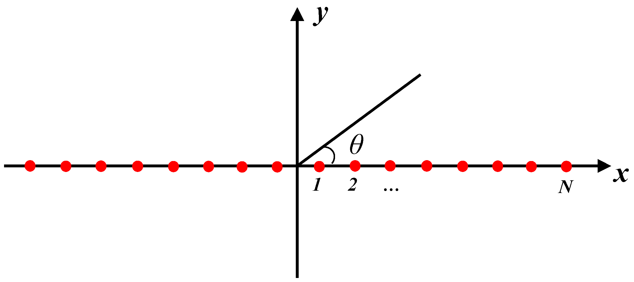
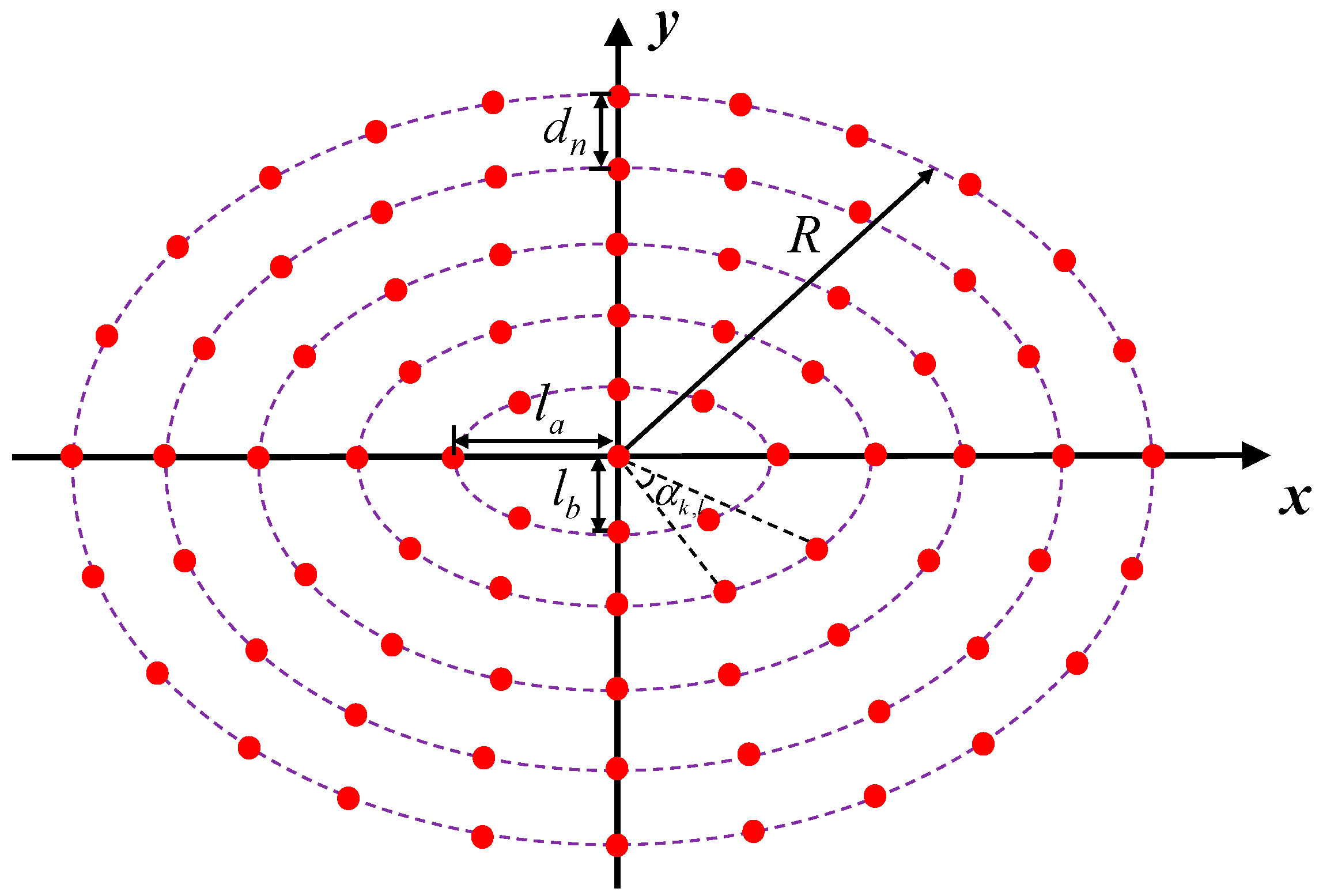
In order to perform the array optimization process reasonably, it is inevitable to integrate the geometrical information of the arrays into the mathematical model of the KOA. The geometric configurations of ULAAs and CEAAs are respectively formed and placed in the designated area of the
x–y plane, and the diagrammatic sketches are shown in
Figure 2 and
Figure 3. In the ULAA model, the
symmetrical elements are used, and each element is formed by a dipole. In the CEAA model, the number of the elements is
, and the concentric rings have the same axis ratio
. Each ring is composed of a different number of dipoles, and in order to ensure the radiation performances of the CEAA, an additional dipole is set at the center of the array. The position angle of each ring element is
. The distance to the adjacent ring is
, and
contributes the maximum aperture of the CEAA. Whether it is a ULAA or CEAA, the related parametric models are generated for the initial arrangement in the beginning of the optimization.
The geometrical information of the arrays, such as the critical parameters amplitude, phase, rotation, and spacing and axial ratio, is set as the design variables (
) of the optimization problems to integrate into the KOA. The generation and representation of these variables are shown in the following equations:
where
denotes the
i-th candidate solution in the
dimensions,
.
and
denote the population size and current search space dimensions, respectively.
denotes a random number within the range of
.
and
denote the upper and lower bounds of the
i-th candidate solution, respectively.
For the purpose of synthesizing patterns with high gain and low SLL, the radiation characteristics are calculated by the full-wave MoM simulation. The full-wave MoM is a commonly used electromagnetic analysis method without approximate consideration of mutual coupling [
31]. The governing equation of the analysis process is shown in a matrix as follows:
where
,
, and
denote the mutual impedance of the
m-th and
p-th elements, the unknown currents, and incident excitation, respectively.
is obtained by the
and
. The gains in all directions can be calculated by the
. Herein, the strategy for the objective function
is set to calculate the difference between the gain of the mainbeam direction (
) and the maximum gain of the other directions [
25,
27].
is defined as:
where
and
are the mainbeam gain and peak SLL, respectively.
is the weight factor that regulates
and
.
It is widely known that the movement of the planets depends on the gravity of the Sun, which can control the direction of their elliptical shape orbit. The existence of the Sun determines that the planets will not move in a straight line towards infinity. The strength or weakness of the gravity is closely related to the current position of the planets and their own masses. In other words, when a planet is closer to the Sun, it is affected by the strong gravitation, and it attempts to increase its velocity within the orbit to avoid being pulled towards the Sun. Thus, the gravitation (
) between the
i-th planet (
) and the Sun (
) is expressed as:
where
is the gravitational constant, which is represented as a function that decreases exponentially over time
for ensuring the accuracy of the object searching.
is the current number of iterations.
denotes the eccentricity of the elliptical shape orbit.
denotes the normalized Euclidian distance between the dimensions
and
.
is an extremely small constant to avoid an error of zero.
is a random value that enriches the variation of
,
.
and
denote the normalized masses of the Sun (
) and any planet (
), respectively.
and
are expressed as:
where the masses of the Sun and planet are related to
.
denotes the random value.
As mentioned before, the planet possesses a faster speed when it gets closer to the Sun, otherwise it will slow down. For the numerous planets near the Sun, through providing and calculating the distance between the two candidate solutions randomly, the velocity of the planets is determined to assist in diversifying the search strategies. For the planets far away from the Sun, the velocity needs to be controlled by the distance of the current candidate solution and a random solution. In this process, the velocity of one celestial body to another is obtained based on the orbital energy conservation (vis viva) equation in general relativity, which is given as:
where
represents the rotation direction of the planets. In order to avoid the local optimum of the KOA,
is introduced to adjust the search direction.
and
are the vectors of a random value.
denotes the normalized Euclidian distance.
and
are random values. The variables
,
, and
involved in the intermediate process are represented as:
where
is a random value within the range of
.
is the major semi-axis in the elliptical orbit based on Kepler’s third law.
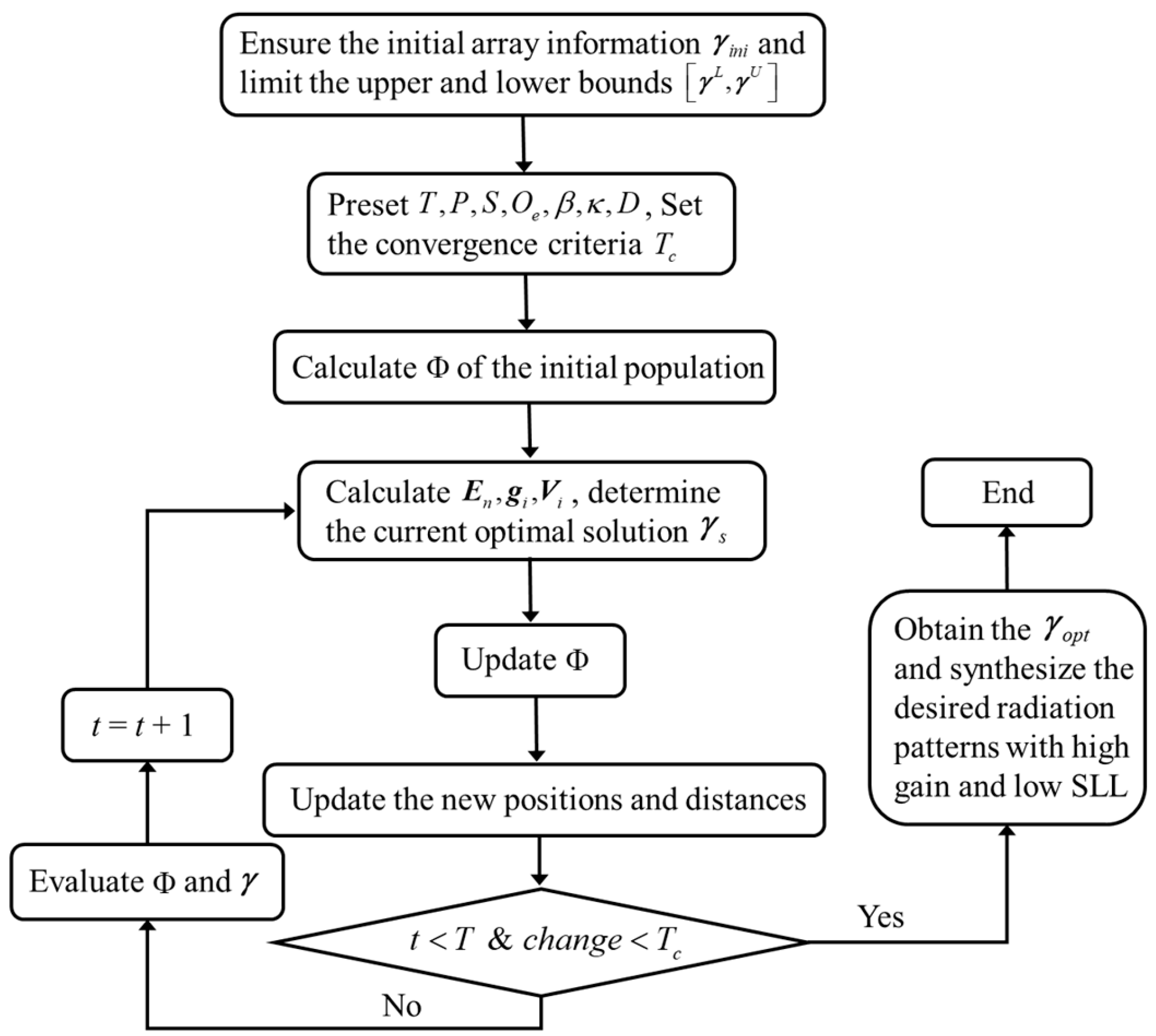
As previously mentioned, all planets revolve around the Sun in elliptical orbits to explore the entire feasible region of the candidate solutions conveniently. In the current iteration step, through simulating the operating process, the new objects’ positions are updated away from the optimal solution. For the nearby candidate solutions, the distances are updated to search the new solutions near the current optimal solution. During the overall iteration process, the desired optimal solution is determined and evaluated by comparing the objective function values, which obtains the required ULAA and CEAA design. Based on this, the array information is introduced into the mathematical model of the KOA to construct the optimization process for the ULAA and CEAA design.
4. Numerical Examples
In this section, typical numerical examples for ULAA and CEAA design optimization are described to achieve the critical parameter designs. Through introducing the rotation angle, amplitude, and phase of the ULAA, as well as the ring spacing and axis ratio of the CEAA separately, the desired patterns are achieved to improve the radiation characteristics of the arrays. In
Figure 2 and
Figure 3, the diagrammatic sketches of the ULAA and CEAA include a series of the rod-shaped dipoles, where each element has a width of 0.04
and height of 0.46
.
denotes the wavelength of the simulation
frequency. All the dipole elements are identical and are each matched with a 50
Ω transmission line. The center of each dipole is applied to a 1 V voltage gap
generator individually. The mainbeam is concentrated in the direction of
, and
belongs to the elevation and azimuth on the
truncation boundary. The width of the mainbeam is
. In the designs of the ULAA, the numbers of the
elements are selected as 24, 36, 48, etc. in the different numerical examples.
The distance of any two adjacent dipoles is 0.5
. In the design of the CEAA, the configuration of
the rod-shaped dipoles is characterized as a concentric elliptical ring with
uniform spacing.
and 5
. During the optimization iteration process, the
number of dipoles and
of each ring element remain constant without
participating in the design. The optimization information of the ULAA and CEAA
includes: the total number of iterations
cannot exceed 200. The convergence criterion
is defined as the variation of
not being greater than
.
are set to 25, 3, 0.5, respectively.
is a random value in
. The design optimization of the ULAA and CEAA is
run by using a computer with 3.60 GHz i7-7700K CPU and 8 GB RAM. Subsequently,
four typical numerical examples are introduced to validate the effectiveness of
the proposed method.
4.1. Amplitude-Only ULAA Example
In the first example, a 28-element ULAA configuration is described to synthesize the radiation pattern by amplitude-only optimization. From here, each dipole element is excited by a 1
V voltage gap generator, where
denotes the excitation amplitude of the element.
The initial value
is set to 1, and the bounds of the variables are
. The comparisons of
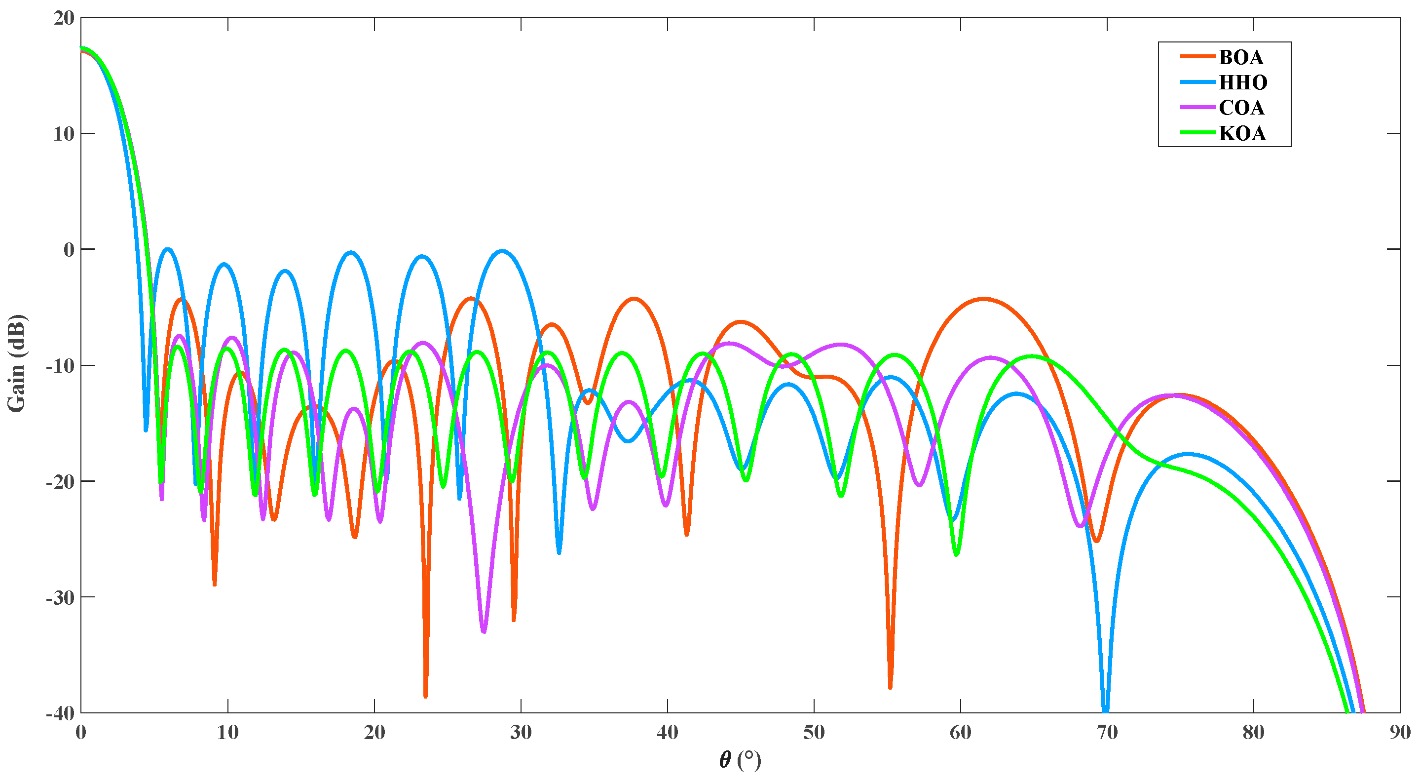
the radiation patterns by amplitude-only optimization are illustrated in
Figure 5
, where
the radiation characteristics of all the synthesis methods are calculated by
the full-wave MoM. It is shown that the HHO algorithm has a gain of 17.33 dB in
the mainbeam direction and a peak SLL of 0.01 dB. Moreover, the BOA and COA
provide peak SLL minimizations of −4.4 dB and −7.5 dB, respectively, meanwhile
both values of
are 17.21 dB. The
proposed KOA method possesses a mainbeam of 17.32 dB and a peak SLL
minimization of −8.45 dB. Although the proposed method has a slightly lower
mainbeam gain compared to the HHO algorithm, it achieves a peak SLL suppression
of over 25.77 dB.
4.2. Phase-Only ULAA Example
In the second example, the phase-only design is provided to calculate the desired radiation patterns with high gain and low SLL by a 30-element ULAA.
denotes the excitation phase of each array
element, and it is excited by a 1
V voltage gap generator.
is 0, and the values of
and
are 0 and
, respectively. In
Figure 6
, based on the BOA, HHO, COA, and proposed method, the radiation
patterns are calculated and compared to characterize the required excitation
phase arrangements. It is seen that the BOA and HHO algorithm bring mainbeams
of 17.66 dB and 17.22 dB, as well as peak SLLs of 0.32 dB and 0.93 dB,
respectively. The optimization result by the COA provides a gain of 17.04 dB in
the main radiation direction and a peak SLL minimization of 0.37 dB. Compared
with the COA, the desired radiation pattern by the proposed method is
synthesized to achieve a lower peak SLL of −1.73 dB, while ensuring the
mainbeam gain remains basically unchanged. From the above-mentioned design
results, it is found that, by reasonably optimizing the excitation amplitudes
and phases of the ULAA based on the proposed method, the required radiation
pattern performances with high gain and low SLL can be obtained.
4.3. Rotation and Amplitude ULAA Example
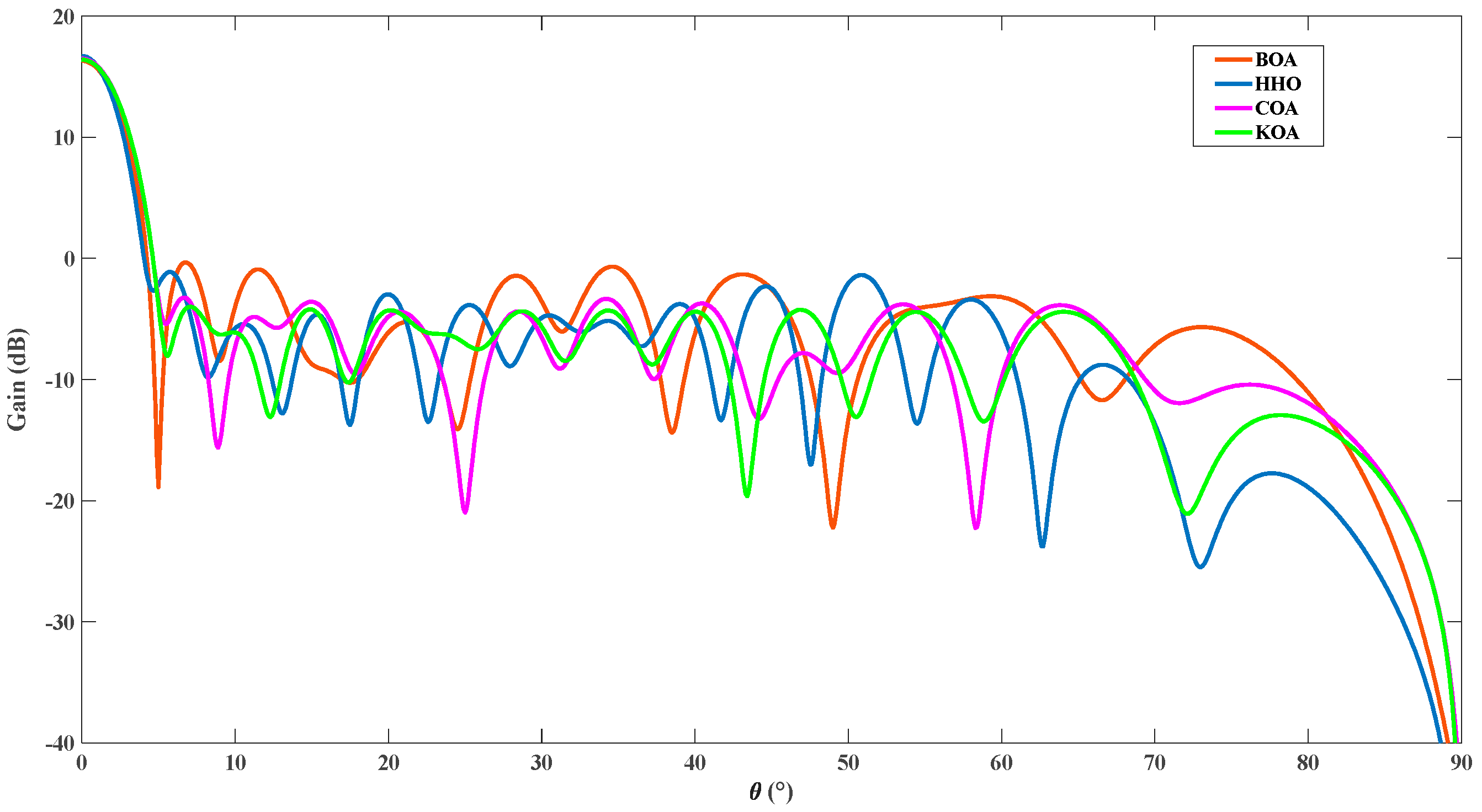
In the third example, in order to introduce the geometry information for the pattern synthesis of the ULAA, a 36-element array configuration is to achieve the collaborative optimization of the rotation angles and excitation amplitudes.
represents the rotation angle (
) and excitation amplitude (
) of each array element, and the initial values are
set to 0 and 1, respectively. The element is excited by a 1
V voltage gap generator. The lower and upper
bounds of the variables are set to
and
, respectively.
Figure 7 shows the comparisons of the radiation patterns by the collaborative optimization of the rotation angles and excitation amplitudes. All the design results are calculated to synthesize patterns by full-wave MoM analysis. It is observed that the gains in the mainbeam direction are 16.71 dB, 16.68 dB, and 16.39 dB, respectively, meanwhile the peak SLLs of the arrays are −0.34 dB, −1.12 dB, and −3.29 dB by the BOA, HHO, and COA. Compared to the three algorithms, the proposed method can get a peak SLL minimization of −4 dB and the maximum difference between the mainbeam gain and peak SLL.
4.4. Spacing and Axis Ratio CEAA Example
In the fourth example, a 142-element CEAA configuration is described to synthesize the radiation pattern by optimizing the spacing and axis ratio of the concentric elliptical ring. The initial CEAA model consists of 6 rings and the number of identical dipoles on each ring is 9, 17, 25, 31, 26, 33.
denotes the distance (
) and axis ratio (
) of each ring, respectively. The initial
elliptical ring spacing
is 0.76, 1.36, 2.09, 2.99, 3.78, 4.70, and
is set to 1. The lower and upper bounds of
and
are
and
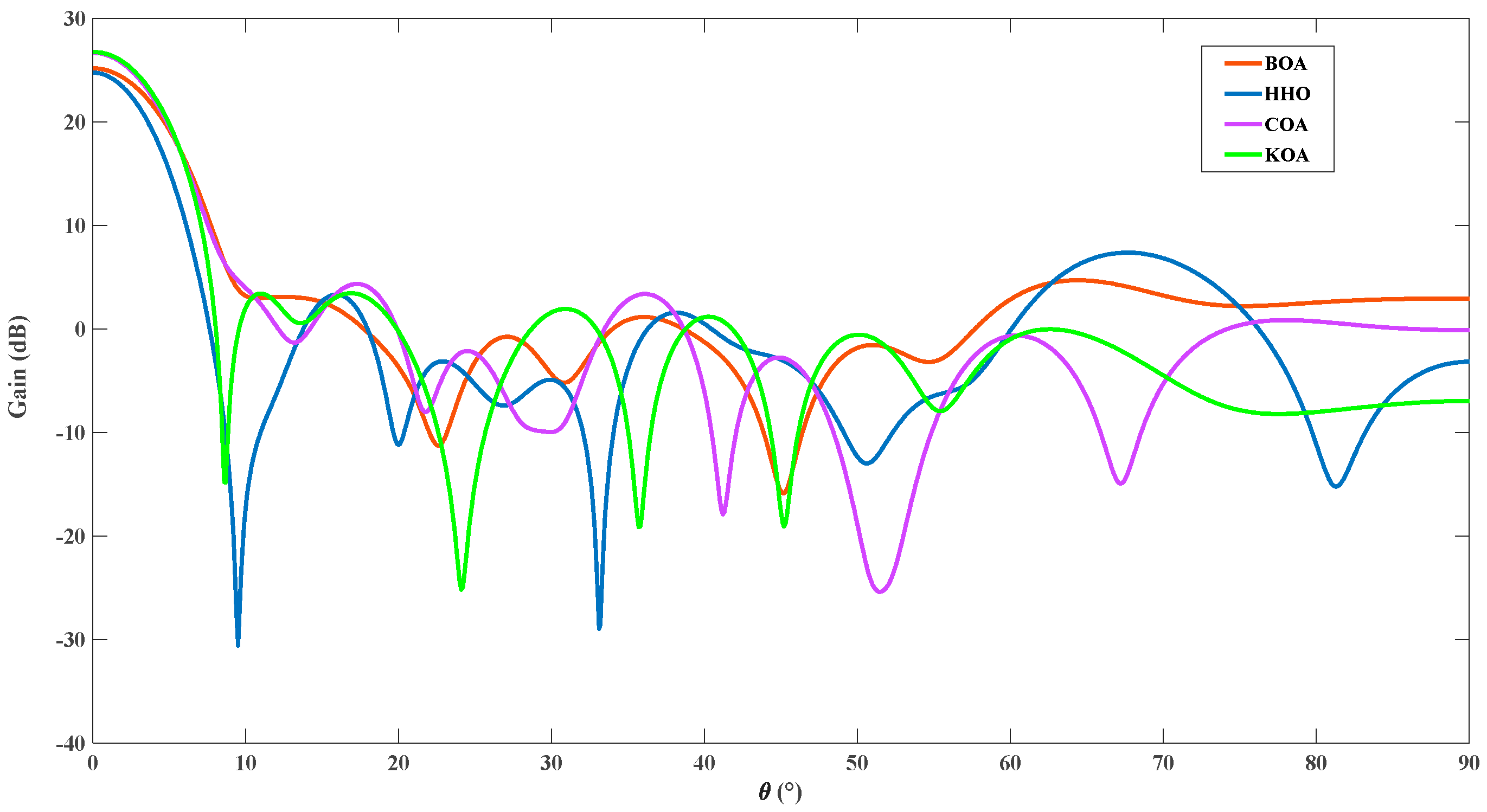
, respectively. All the elements are excited by a 1 V voltage gap generator. The design results, including those of the BOA, HHO, COA, and proposed method, are calculated to synthesize the patterns by the full-wave MoM analysis.
Figure 8 illustrates the comparisons of the four radiation patterns by the optimization of the ring spacing and axis ratio. It is seen that the BOA and HHO generate mainbeam gains of 25.15 dB and 24.74 dB, and the peak SLLs of the arrays are 4.65 dB and 7.35 dB, respectively. The design result of the COA provides a mainbeam gain of 26.66 dB, and the peak SLL is suppressed by 4.3 dB. The radiation pattern of the KOA possesses a higher gain of 26.74 dB in the mainbeam direction and lower peak SLL of 3.4 dB. Compared with the three algorithms, the proposed method achieves extra peak SLL suppression of 3.95 dB, 1.25 dB, and 0.9 dB, respectively, while guaranteeing the improvement of the mainbeam gain.
The above-mentioned discussion demonstrates that the proposed KOA method achieves significant suppression of the peak SLL and ensures a gain in the mainbeam direction by optimizing the rotation angle, amplitude, phase, and ring spacing and axis ratio, which improves the radiation characteristics and generates the desired patterns of the ULAA and CEAA.

