Article

Thermo-Mechanical Coupled Characteristics for the Non-Axisymmetric Outer Ring of the High-Speed Rail Axle Box Bearing with Embedded Intelligent Sensor Slots

1
College of Mechanical and Vehicle Engineering, Changsha University of Science and Technology, Changsha 410114, China
2
Hunan Provincial Key Laboratory of High-Performance Intelligent Manufacturing Key Technologies for Mechanical Equipment, Changsha 410114, China
*
Author to whom correspondence should be addressed.
Symmetry 2025, 17(10), 1667; https://doi.org/10.3390/sym17101667
Submission received: 28 July 2025 / Revised: 20 August 2025 / Accepted: 3 September 2025 / Published: 6 October 2025
(This article belongs to the Section Engineering and Materials)

Abstract

As high-speed railway systems continue to develop toward intelligent operation, axle box bearings integrated with sensors have become key components for real-time condition monitoring. However, introducing sensor-embedded slots disrupts the structural continuity and thermal conduction paths of traditional bearing rings. This results in localized stress concentrations and thermal distortion, which compromise the bearing’s overall performance and service life. This study focuses on a double-row tapered roller bearing used in axle boxes and develops a multi-physics finite element model incorporating the effects of sensor-embedded grooves, based on Hertzian contact theory and the Palmgren frictional heat model. Both contact load verification and thermo-mechanical coupling analysis were performed to evaluate the influence of two key design parameters—groove depth and arc length—on equivalent stress, temperature distribution, and thermo-mechanical coupling deformation. The results show that the embedded slot structure significantly alters the local thermodynamic response. Especially when the slot depth reaches a certain value, both stress and deformation due to thermo-mechanical effects exhibit obvious nonlinear escalation. During the design process, the length and depth of the arc-shaped embedded slot, among other parameters, should be strictly controlled. The study of the stress and temperature characteristics under the thermos-mechanical coupling effect of the axle box bearing is of crucial importance for the design of the intelligent bearing body structure and safety assessment.

1. Introduction

With the continuous advancement of high-speed railway technology, there is a greater demand for monitoring the operating conditions of key components under service conditions. As the core load-bearing element connecting the axle and the bogie, the axle box bearing is subjected to long-term exposure to high speed and heavy loads. Its thermal stability and fatigue life are directly related to the operational safety and maintenance cost of the train. In recent years, the development of intelligent high-speed railway equipment has gradually promoted the need for real-time perception and health assessment of key components. The integration of embedded sensor technology into bearing structures has become an effective approach to realizing intelligent monitoring.
In current intelligent bearing designs, embedded grooves are typically machined locally on the bearing rings to accommodate micro-sensor units for real-time acquisition of parameters such as temperature and stress. With the development of flexible circuit board technology, flexible circuit boards integrated with sensors can be embedded as sensing elements into the bearing body, effectively enhancing the design flexibility. The flexible circuit boards integrated with sensors and chips can be embedded in slots in an arc shape. However, the introduction of such arc-shaped grooves disrupts the axisymmetric structural feature of the ring, the original structural continuity, and the thermal conduction paths, leading to local stress concentration and thermal distortion, which can adversely affect the load-bearing performance and service life of the bearing. For example, Permana et al. [1] conducted a finite element analysis on the effect of semi-circular grooves machined on shaft surfaces, and the results indicated that an appropriately designed groove geometry can reduce the stress concentration factor by approximately 10%, thereby improving the load-carrying performance of the structure. Xu et al. [2] developed a thermo-mechanical coupled finite element model for rolling bearings and found that, under high-speed operating conditions, the maximum temperature in the bearing contact region could approach 120 °C, accompanied by a pronounced temperature gradient that significantly affects local thermal deformation. These quantitative findings further highlight that groove structures in intelligent bearings may induce non-negligible local stress and thermal effects. Therefore, it is urgent that there is evaluation of the influence mechanism of the embedded groove design parameters on the thermo-mechanical response of the bearing from the perspective of multi-physical field coupling, so as to provide theoretical support for the design of the embedded groove structure of intelligent bearings.
The mechanical response analysis of high-speed train axle box bearings under multi-physical loads is increasingly becoming a key research direction for ensuring their thermal stability and structural safety. Under embedded groove conditions, the study of the mechanism of thermo-mechanical coupling deformation and stress distribution is of vital importance for the assessment of structural strength and life. Previous studies have made progress in various bearing types and typical load scenarios. Li et al. [3], based on Hertzian contact theory and mesh network methods, established a dynamic thermo-mechanical coupling model for assembled bearings in the winding wire feeding system, revealing the effects of rotational speed and load on frictional performance and thermal behavior. Zhang et al. [4] developed a thermal model for angular contact ball bearings considering the temperature-dependent viscosity of lubricants and validated it through parameterized ANSYS R18.2 simulations. Tang et al. [5] investigated the thermal issues in aero-engine dual-row angular contact ball bearings and proposed a thermo-mechanical dynamic model, combined with the GSTIFF algorithm to analyze the effects of process and structural parameters. Wang et al. [6], based on network modeling, constructed a thermo-mechanical coupling model for axle box bearings in high-speed trains. By comprehensively considering variations in frictional heating and lubricant viscosity, they validated the model through bench experiments and analyzed the effects of speed, load, fault types, and ambient temperature on the bearing temperature rise. Wang et al. [7] developed a transient thermal field model for the wheelset axle system of high-speed trains and analyzed the effects of speed, load, and fault categories on temperature distribution, validating model accuracy via experiments to provide theoretical support for safe operation. Yang et al. [8] constructed a speed–environment coupling thermal model for axle box bearings, confirming its effectiveness through experiments. They showed that air flow parameters, environmental conditions, and surface heat transfer coefficients significantly affect bearing heating behavior under different loads. Ma et al. [9] established a 3D axle-bearing coupling model and verified it through experiments, identifying that wheelset misalignment and wheel polygonal wear can cause abnormal vibration, and suggested detecting eccentricity and bearing looseness through temperature field variation. Chen et al. [10] used finite element modeling to analyze the influence of outer ring grooves on bearing performance, aiding in intelligent bearing sensor integration and condition monitoring. Xue et al. [11] improved transient mesh generation and established a thermo-mechanical dynamic model considering oil circulation and heat transfer effects targeting aero-engine dual-row angular contact ball bearings. Liu et al. [12] built a high-speed motorized spindle thermo-mechanical-electrical coupling model, and experimental verification showed that coupling effects increased model accuracy. It was concluded that coupling factors should be integrated into simulation frameworks. Chang et al. [13] focused on the transient problem of rotor systems in aero-engines, proposing a unified integral solution framework combining variational and finite element methods, and addressed solution difficulties in conventional subdomain methods for multi-physics coupling.
In addition to thermo-mechanical coupling effects, the geometric parameters of the embedded grooves have also drawn attention. Zhou et al. [14] proposed a method for detecting bearing seat groove deformation under high-speed loading using eddy current sensors. Li et al. [15] used finite element analysis to compare spiral and annular grooves, showing that spiral grooves with five turns and 2.5 mm pitch minimized axial displacement and deformation, while annular grooves tended to concentrate stress, providing critical data for groove optimization. Yang et al. [16] developed a thermal–hydrodynamic model for gear-shaft systems with grooved bearings, using finite difference and experimental validation to analyze the influence of thread groove parameters on bearing performance. Wang et al. [17] analyzed the deformation characteristics of hydrodynamic bearings with various slot shapes (rectangular, front-arc, dual-arc) through fluid–solid thermal coupling and demonstrated that water temperature and rotor speed significantly affect bush deformation. Gutarevich et al. [18] proposed reducing the vibration influence of track grooves under dynamic loads by adding damping structures. This will be an important research direction for improving the loading capacity. Wu et al. [19] examined how casting and forging methods affect groove structure precision and overall assembly strength, finding forged grooves to be more stable. Luan et al. [20] developed a multi-objective optimization model, discovering that spiral groove parameters can be tuned to improve stepped pressure support stiffness. Fesanghary and Khonsari [21] used optimization algorithms to design optimal groove profiles, showing that “heart-shaped” and “spiral” grooves can improve load capacity by up to 36% when optimized for aspect ratio. Brito et al. [22] compared single and double-grooved bearings and found that flow reversal and negative temperature rise reduced stability, recommending an adaptive switching strategy. Xu et al. [23] developed a turbulent lubrication model for V-groove bearings, demonstrating superior thermal management and load support at high speed. Zhang et al. [24] used particle swarm optimization to analyze how groove length affects friction, identifying an elongated trapezoidal shape with minimal eccentricity as optimal. Bättig et al. [25] experimentally confirmed that even a slight change in groove angle can triple the critical speed of instability, offering excellent stability and machining compatibility.
However, previous studies on traditional bearings focused on thermal fields or bearing contact mechanics. They only considered the bearing load, rarely taking into account the coupling effect of the temperature field and the force field. Studies on the thermo-mechanical coupling characteristics of the intelligent bearing body were rarely concerned with this aspect. These shortcomings will make it difficult to predict the local stress and temperature of the sensor-embedded slot of the intelligent bearing. Therefore, it is necessary to study the stress characteristics of the sensor-embedded slot of the axle box bearing under the influence of thermo-mechanical coupling effects.

2. Theoretical Model

2.1. Contact Load Model

During the operation of axle box bearings, the rollers are subjected to axial load F a , radial load F r , and external moment M . To establish the force relationship on the roller, a local coordinate system is introduced and a three-directional force equilibrium model is constructed, expressed as follows [26]:
F o sin α o F i sin α i F f sin α f = 0
F o cos α o F i cos α i + F f cos α f = 0
where F o , F i , and F f are the contact forces between the roller and the outer ring, inner ring, and outer-ring rib, respectively, and α o , α i , and α f are the corresponding contact angles.
By projecting the forces of Z rollers, the static equilibrium of the entire bearing can be expressed as
F r = n = 1 2 j = 1 Z F o cos α o cos φ j
F a = n 1 2 j = 1 2 F s sin α o
M = n = 1 2 j = 1 Z ( 1 2 d c F o cos φ j cos α o + r m F o cos φ j sin α o )
where φ j is the angular position of the j -th roller, d c is the radial distance from the load application point to the center, and r m is the pitch circle radius of the rollers.

2.2. Contact Stress Model

The contact between the roller and the raceways is line contact, which follows Hertzian contact theory. Under a load F , the contact half-width L and maximum contact stress p are given by
L = 4 R F π I E
p = E F π l R
where R is the equivalent curvature radius, l is the effective contact length of the roller, and E is the equivalent elastic modulus, defined as
1 E = 1 v 1 2 E 1 + 1 v 2 2 E 2

2.3. Heat Generation Model

During bearing operation, energy dissipation occurs due to lubricant shear and rolling contact. The Palmgren frictional moment M can be decomposed as
M = M v + M L
where M v is the viscous friction moment (related to lubricant properties and speed), and M L is the contact friction moment (related to load).
For different working conditions, the viscous friction moment M v is given by the following.
When v n 2000 ,
M v = 10 7 f 0 ( ν n ) 2 / 3 d m 3
When v n < 2000 ,
M v = 160 × 10 7 f 0 d m 3
where d m is the pitch diameter, f 0 is the empirical coefficient, n is the rotational speed, and v is the kinematic viscosity.
The contact friction moment M L is expressed as
M L = f 1 P d m
where f 1 is the contact friction coefficient and P is the equivalent load; the value can refer to [27].
The generated heat power Q can be estimated by
Q = 1.05 × 10 4 n M
where M is the total frictional moment of the bearing.

2.4. Heat Transfer Modele

Under the operating conditions considered in this study, the ambient temperature is relatively low and the maximum temperature of the bearing is not high either. In this case, heat radiation can be neglected compared to heat convection, and the outer ring is surrounded by a semi-enclosed axle box structure. Therefore, the influence of heat radiation can be ignored. Bearing heat is dissipated through both external air and internal lubricant interfaces. The heat transfer mechanisms mainly include natural convection and forced convection [28]. Depending on the region and flow type, the following theoretical models are constructed:
  • Natural convection heat transfer
The outer surface of the outer ring is typically exposed to air, forming a natural convection boundary. The heat transfer coefficient is expressed through empirical correlations involving the Nusselt number N u , the Grashof number G r , and the Prandtl number P r :
N u = C G r P r n
h nat = N u k L
where k is the thermal conductivity of the air at operating temperature, L is the characteristic length, and C , n are empirical constants related to surface geometry and flow mode, respectively;
2.
Forced convection heat transfer
Relative motion between the rollers and raceways shears the lubricant, forming typical forced convection flow. The Nusselt number is estimated via the Dittus–Boelter equation:
N u = 0.023 R e 0.8 P r 0.3
h for = N u k D
where R e is the Reynolds number, and D is the characteristic dimension of the flow channel.

3. Bearing Structure and Finite Element Modeling

3.1. Bearing Geometry and Structural Parameters

The axle box bearing used in this study is a double-row tapered roller bearing. It consists of one cage, one outer ring, two symmetrically arranged inner rings, an intermediate ring, and 38 tapered rollers. The main structural parameters are listed in Table 1, and the three-dimensional geometric model is shown in Figure 1.

3.2. Design Parameters of the Arc- Shaped Embedded Slot for Flexible Circuit Board

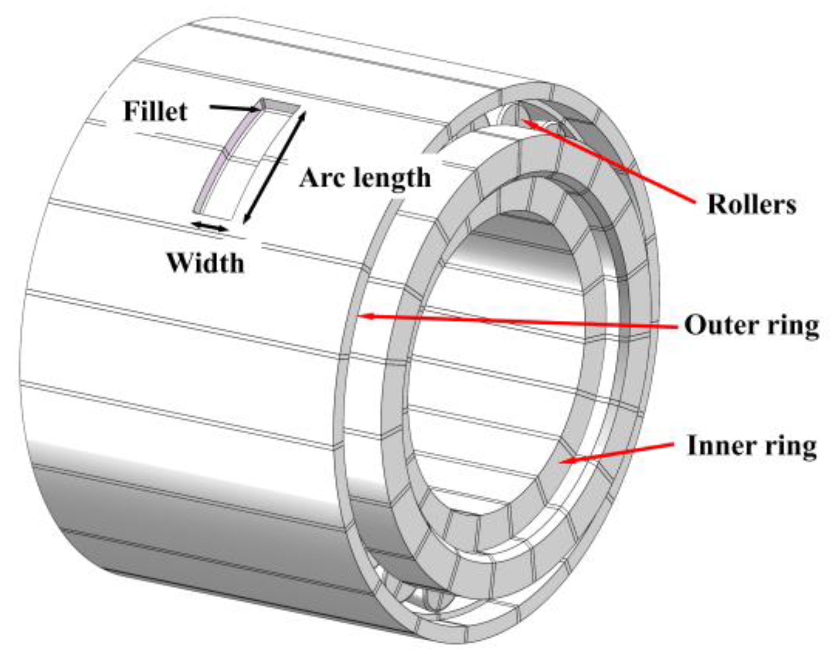
To enable sensor integration, an annular embedded slot was designed on the outer ring near the position corresponding to the intermediate ring. The groove has a fixed width of 17 mm, and the radius of fillet is 1 mm. Groove depth and arc length were treated as variables for parametric analysis. The schematic diagram of the axle box bearing with an embedded slot is shown in Figure 2.

3.3. Finite Element Modeling and Contact Definition

3.3.1. Contact Settings

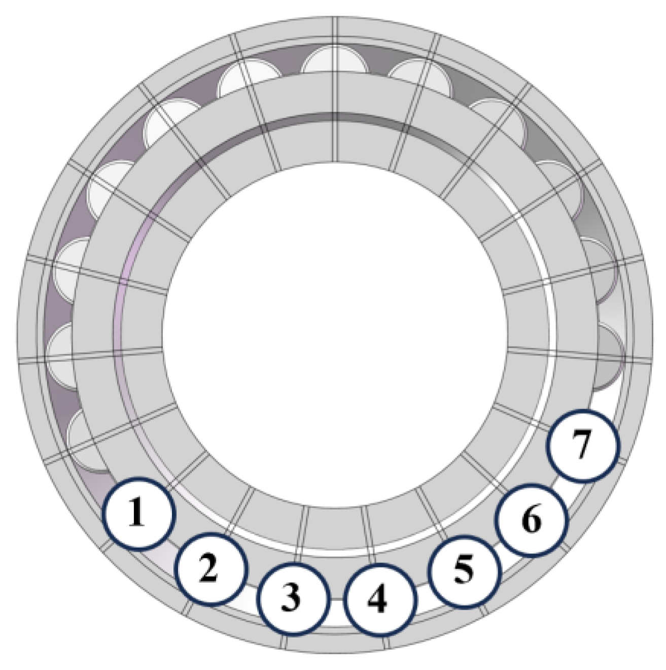
To capture the thermo-mechanical coupling response in the contact region of tapered rollers and slot area, local slices of 2 mm width were created in the contact zones between the rollers and the inner and outer rings. The bearing contains 38 rollers, corresponding to 38 slices, with each roller associated with one inner and one outer ring slice—resulting in 19 inner ring slices and 19 outer ring slices, as shown in Figure 3.
The contact between the inner ring and the mandrel was defined as bonded contact to simulate the rigid connection in the actual assembly. All other contact pairs were defined as frictional contacts with a friction coefficient of 0.002, which falls within the typical range for low-friction rolling contacts. The contact setup is as follows:
  • 19 contact pairs are defined between the rollers and the inner ring;
  • 19 contact pairs are defined between the rollers and the outer ring;
  • One bonded contact is defined between the mandrel and the inner ring.
In the load transmission path, the inner ring transfers the load to the roller, and the roller then transfers the load to the outer ring. Therefore,
  • In the “inner ring–roller” contact pair, the roller is set as the contact surface and the inner ring as the target surface;
  • In the “roller–outer ring” contact pair, the roller is the contact surface and the outer ring the target surface.
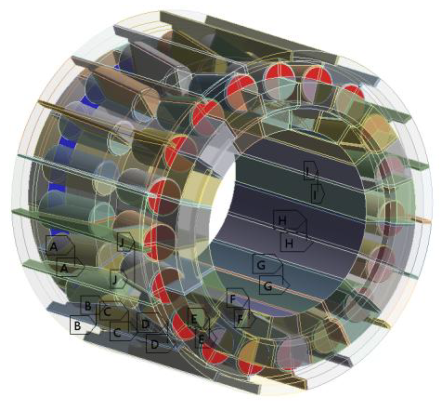
The contact stiffness factor was set to 0.5, with no stiffness update. The damping coefficient was set to 0.1. The automatic time step technology and the contact algorithm of “adjust to contact” were adopted. The contact setup is illustrated in Figure 4.

3.3.2. Finite Element Meshing

Based on the finite element method, the mesh generation consists of three primary components, and the meshed bearing model is shown in Figure 5:
  • Rollers: the slices use non-uniform swept meshes with local refinement of eight divisions and a sweep bias set to eight, with a mesh size of 2 mm. The rest of the roller uses 10 mm tetrahedral elements;
  • Inner ring: the slices use uniform swept meshes with eight divisions and a mesh size of 2 mm. The remaining region is meshed with 10 mm swept elements;
  • Outer ring: the slices use uniform swept meshes with eight divisions and a mesh size of 2 mm. The remaining region is also meshed with 10 mm swept elements.
Furthermore, due to the complex geometry shape of the embedded slot, the embedded groove region was meshed using tetrahedral elements with a size of 1 mm. The assembled model contained approximately 550,000 elements in total. An iterative solver was employed with a step end time of 1 s, and the automatic time step function was enabled. To ensure numerical stability, weak springs were activated, the contact formulation was set to program-controlled, and the large deflection and stabilization options were turned off. The output requests included nodal stresses, contact results, and strain data for post-processing.

3.4. Material Properties and Boundary Conditions

3.4.1. Material Properties

The inner and outer rings, as well as the rollers, are made of GCr15 high-carbon chromium bearing steel. The key material properties are as follows [29]: density 7850 kg/m3, Young’s modulus 208 GPa, and Poisson’s ratio 0.3.
In this study, the mechanical and thermal properties of GCr15 bearing steel were assumed to remain constant over the investigated temperature range; as the simulation temperatures are relatively low, the variations of Young’s modulus, Poisson’s ratio and thermal conductivity within this range can be disregarded for engineering purposes.
In addition, all the sensing elements integrated into the embedded slot adopt SiCN-based thin-film materials (e.g., SiCN-C and SiCN-ITO), which exhibit excellent thermal stability, maintaining stable electrical and mechanical performance up to at least 200 °C. This ensures reliable operation of the sensors under potential local overheating conditions in service.

3.4.2. Applied Loads and Constraints

To realistically simulate the load characteristics during service, the following boundary and loading conditions were applied to the model (as shown in Figure 6):
  • The outer surface of the outer ring was fully constrained, fixing all translational and rotational degrees of freedom to simulate the constraints from the bearing housing;
  • A virtual mandrel was added to the inner ring. A radial load of 110 kN was applied through the mandrel to represent the actual operational load.

4. Load Analysis and Model Validation

4.1. Validation of Roller Load Distribution

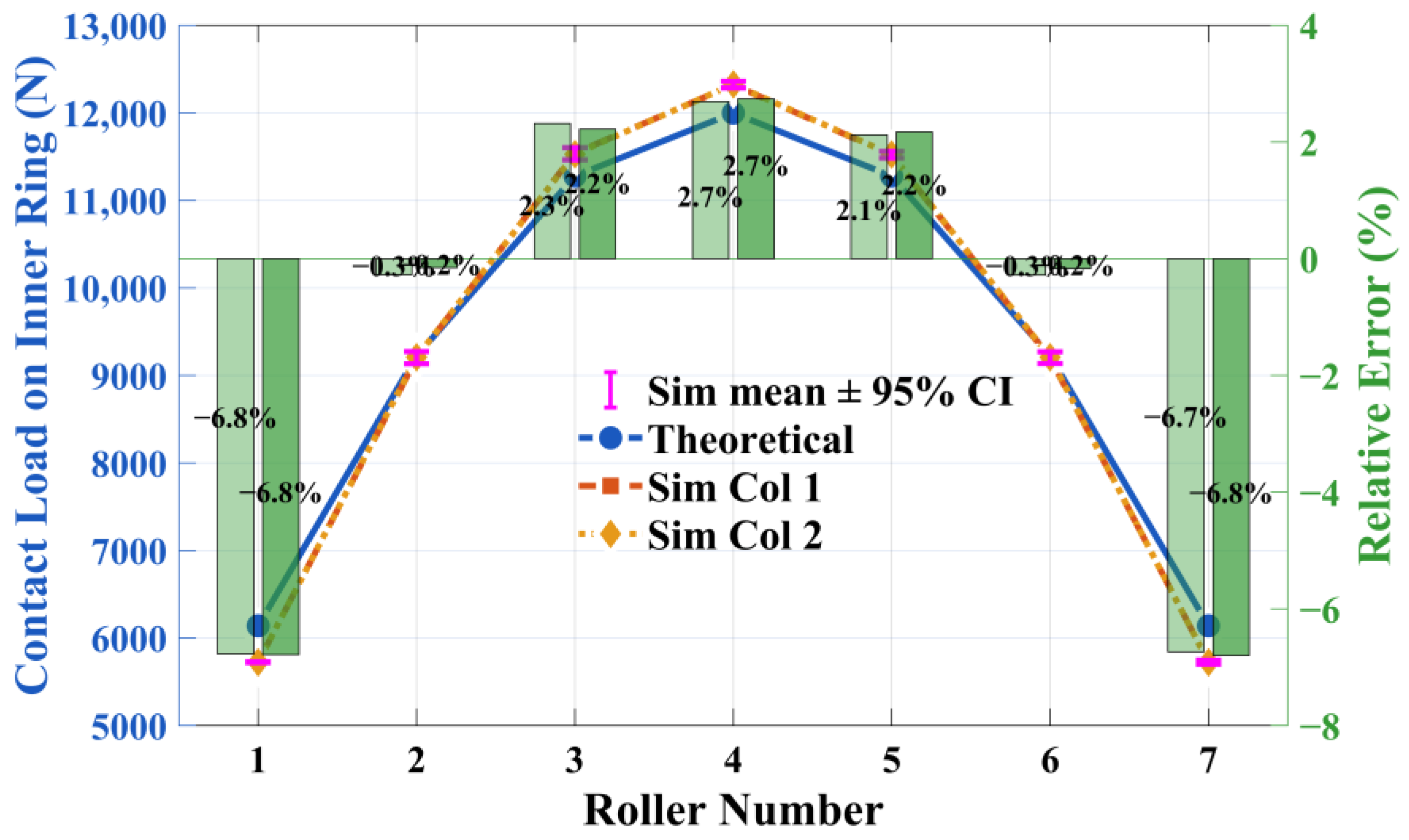
To analyze the load-bearing behavior of the rollers, each roller in the bearing was numbered, as shown in Figure 3. Using the finite element model, the contact load of each roller in the double-row tapered roller bearing was obtained. Figure 7 presents the comparison between the finite-element simulated values and the theoretical results, together with their relative errors and the 95% confidence intervals (CIs) of the simulated mean values. The inclusion of CIs quantitatively illustrates the variability between repeated simulations. It can be seen that the CIs are narrow across all rollers, indicating high repeatability of the simulation results. Under an applied bearing load of 110 kN, rollers 1–7 are the primary load-bearing elements. The simulated load values for these rollers deviate from the analytical solutions by less than 6.8%, verifying the reliability and accuracy of the model in predicting the load distribution.

4.2. Validation of Roller Contact Stress Distribution

To further verify the validity of the model, the contact stress of each roller was compared with the analytical results derived from Hertz contact theory, as shown in Figure 8.
The plotted 95% confidence intervals (CIs) represent the dispersion of repeated simulation results. The relatively short CI bars across all rollers confirm the good numerical stability of the simulations.
The simulated stress distribution shows excellent agreement with the theoretical trend and peak magnitudes, and the small errors meet the accuracy requirements for engineering applications.
This validation further confirms that the developed model is well defined in terms of structural boundaries, mesh generation, and contact settings, and is suitable for subsequent thermo-mechanical coupling analysis.
In the above numerical validation, the lubrication condition was considered by incorporating the physical properties of Mobilith SHC 100 grease (density, viscosity, thermal conductivity, and Prandtl number) into the frictional heat generation model. Given the high manufacturing accuracy of the bearing surfaces (less than Ra 0.4), the influence of surface roughness on the contact pressure distribution is minimal and can be neglected in the overall analysis.

4.3. Validation of Mesh Independence

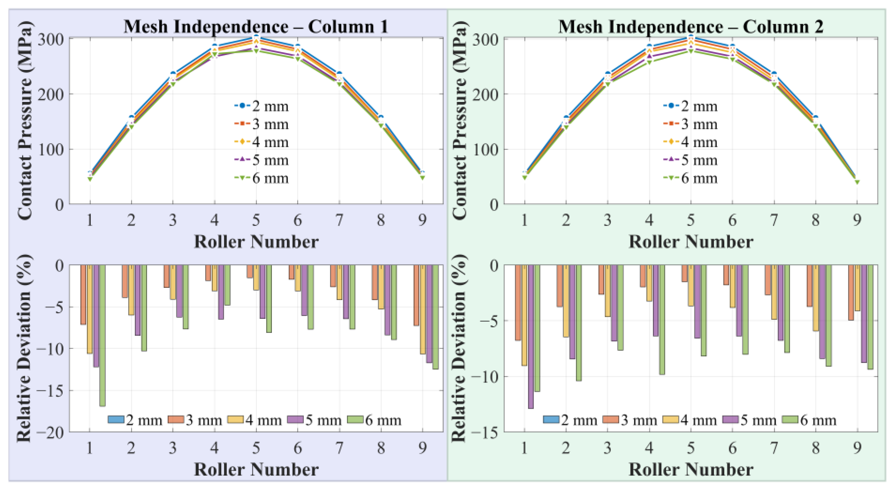
To verify the rationality of the selected mesh size and the convergence of the numerical results, a mesh independence study was conducted by applying element sizes of 2 mm, 3 mm, 4 mm, 5 mm, and 6 mm to the contact slice regions between the rollers and the inner and outer rings. The contact pressure distributions of nine representative rollers in each of the two columns were extracted, and the results obtained with different mesh sizes were compared against those of the finest mesh of 2 mm as the reference. The relative deviations were also calculated.
As shown in Figure 9, with progressive mesh refinement, the contact pressure distributions exhibit a monotonic convergence trend, and the 3 mm mesh already reproduces the overall distribution pattern well. Considering both computational accuracy and efficiency, a 2 mm mesh size was selected for the contact slice regions to ensure the reliability of subsequent simulation results.

5. Thermo-Mechanical Coupling Analysis

To systematically investigate the influence of the embedded slot structure on the thermo-mechanical response of axle box bearings, multiple sets of thermo-mechanical coupled simulations were conducted based on the previously established model. Through comparative analyses of the temperature field, stress field, and thermal deformation, the effects of different slot design parameters were revealed, and recommended parameter ranges were proposed.

5.1. Boundary Conditions and Heat Source Definition

This study adopts a typical high-speed-train operating condition as the input boundary condition. An axial load of 50 kN and a radial load of 110 kN were applied. The ambient temperature was set to 25 °C, and the initial structural temperature was set to 22 °C. According to the description in Section 2, the total amount of frictional heat generated was calculated to be 11,469.93 W, which was distributed in a ratio of 2:1:1 among the rollers, the inner ring, and the outer ring. In the thermal power distribution, considering that the rollers and the inner/outer rings have identical physical properties, and based on the findings of Burton [30] and Li [31], the frictional heat generated between the roller and the ring raceway can be distributed equally (1:1) across the contact interface. This means that each contact interface (roller–inner ring, roller–outer ring) carries the same heat flux. Given the operational characteristics of a double-row tapered roller bearing, each roller contacts both the inner and outer rings once during rotation. Therefore, the roller receives the total heat from two contact interfaces, whereas the inner and outer rings each bear the heat from only one contact interface. Consequently, the total frictional heat can be logically distributed among the rollers, inner ring, and outer ring in a ratio of 2:1:1.

5.2. Thermal Field Response Analysis

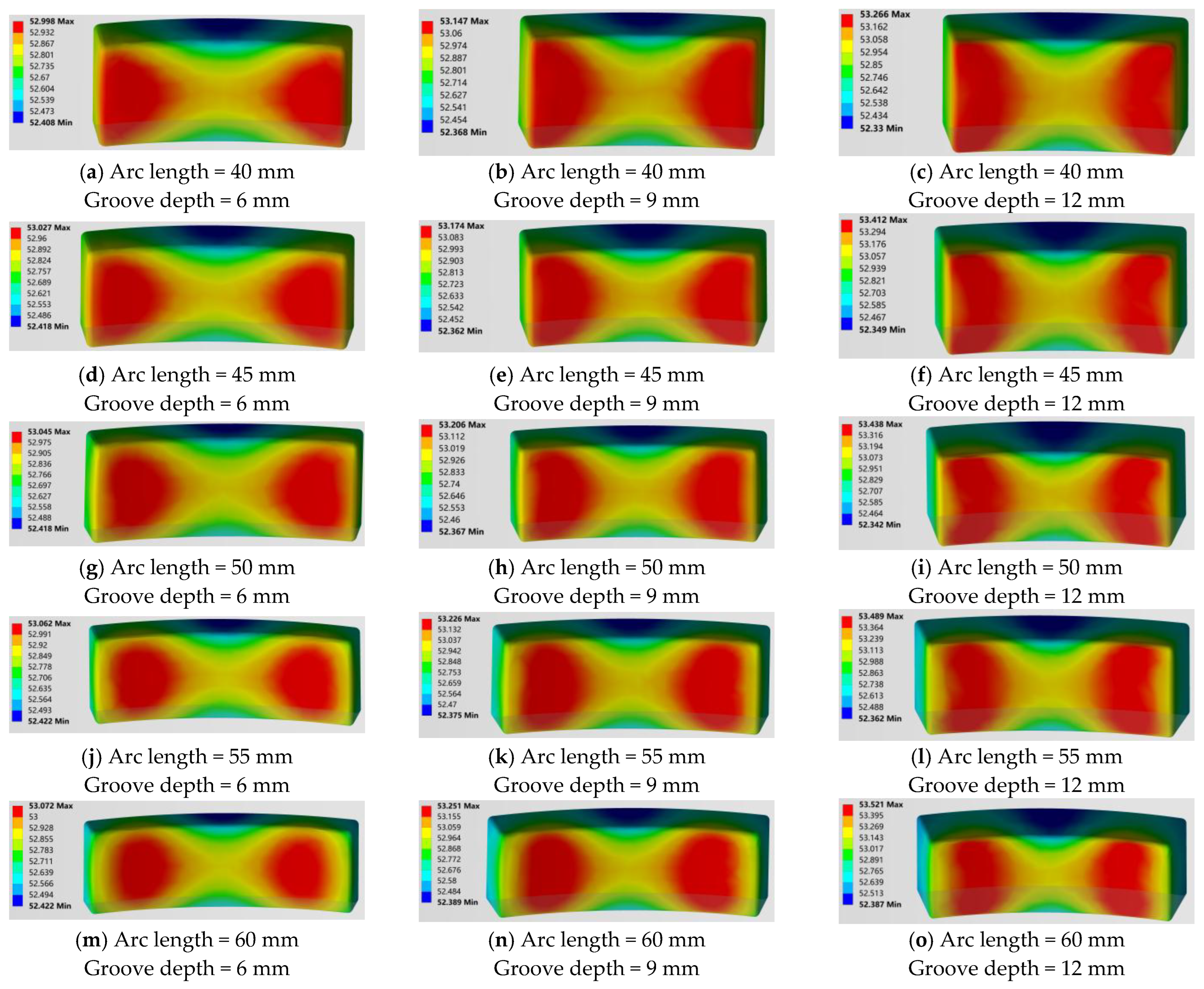
Figure 10 shows the steady-state temperature distributions of the embedded slot under different design parameters. The analysis reveals the following:
  • The temperature peak is concentrated in the contact region between the roller and the inner ring;
  • As groove depth and arc length increase, the temperature in the slot region gradually rises;
  • The temperature field exhibits significant symmetry, and thermal gradients occur on both sides of the groove, potentially inducing local thermal distortion.
To control the temperature-rise value and the heat accumulation, it is recommended that the depth of the groove should not exceed 9 mm.

5.3. Coupled Stress Field and Local Structural Response

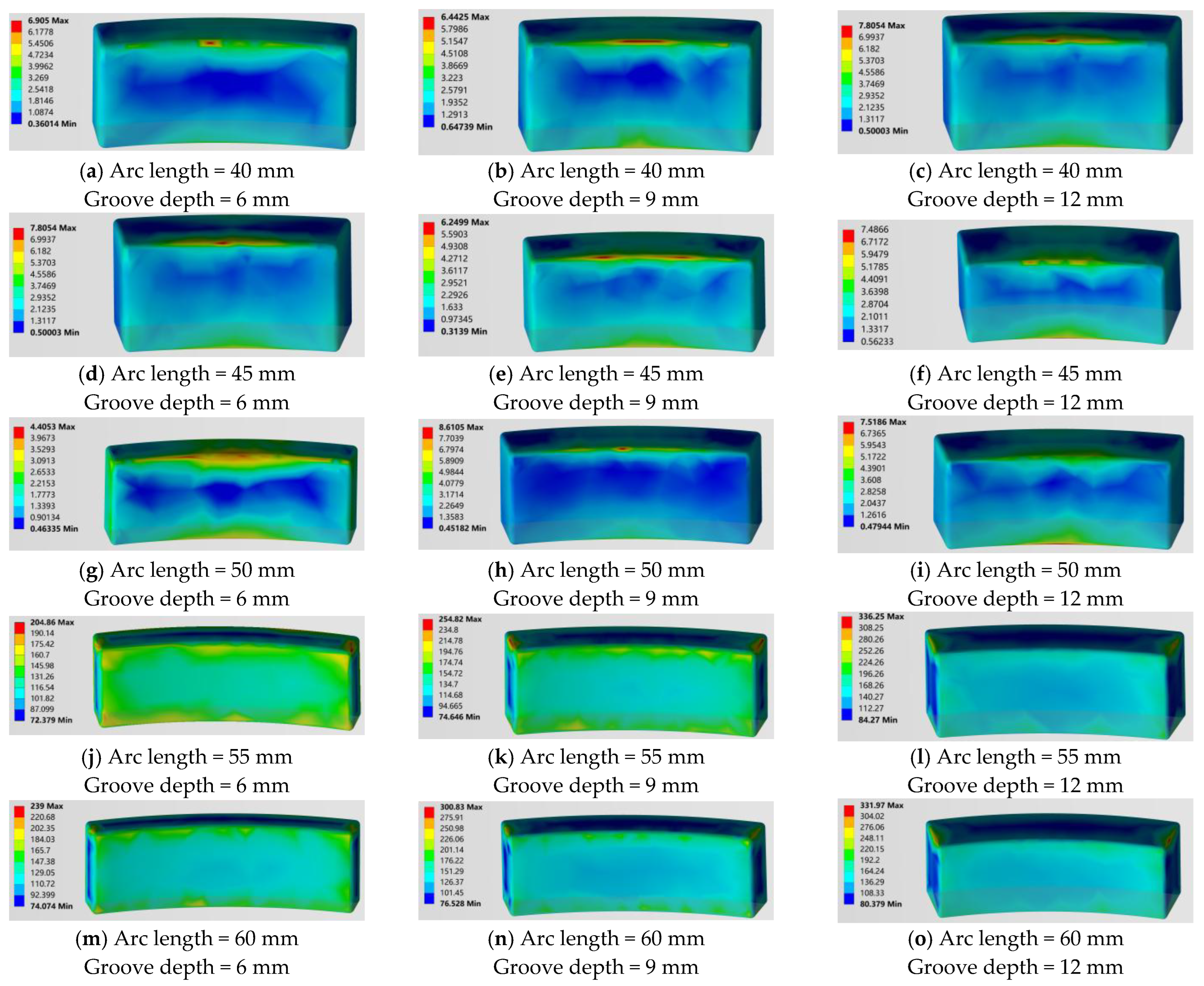
Figure 11 presents the equivalent stress distributions under different design parameters. The main conclusions are as follows:
  • High-stress regions are primarily located at the groove shoulder transitions, where the disruption of structural continuity is the main cause of stress intensification;
  • When the arc length exceeds 55 mm, pronounced stress concentrations appear at the edges of the groove, with maximum equivalent stress reaching 331.97 MPa, approximately 60% of the yield strength of GCr15-bearing steel;
  • Structural strength significantly deteriorates under conditions of large groove depth and long arc length.
The simulation results of this study show that when the arc length increases from 50 mm to 55 mm, both the local stress and thermal deformation exhibit a pronounced nonlinear rise, indicating that 50 mm can be regarded as a safe upper limit close to the critical threshold. To avoid failure due to stress concentration, it is recommended that the arc length should not exceed 50 mm in design. Taking the yield strength of GCr15 steel as 550 MPa, the maximum stress of 336.25 MPa corresponds to a safety factor of approximately 1.64. For all slot depth and arc length combinations considered, the safety factor remains above 1.5, indicating that the structural strength requirement is satisfied.

5.4. Sensitivity Analysis of Ambient Temperature

To investigate the influence of ambient temperature on the thermal behavior of the grooved outer ring, additional simulations were conducted under three representative service temperatures: −40 °C, 25 °C, and +50 °C. For each temperature, groove depths ranging from 6 mm to 12 mm were analyzed with a fixed groove arc length of 45 mm and width of 20 mm. The corresponding maximum temperatures in the groove region are presented in Figure 12.
Across the examined groove depths, the maximum temperature increased slightly with groove depth for all three ambient temperatures. At −40 °C, the temperature ranged from −11.973 °C to −11.588 °C, with a maximum difference of approximately 0.385 °C. At 25 °C, the range was 53.027 °C to 53.412 °C, with a maximum difference of about 0.385 °C. At +50 °C, the range was 78.027 °C to 78.412 °C, with a maximum difference of approximately 0.385 °C.
These results indicate that, within the examined range (−40 °C to +50 °C), ambient temperature has only a minor effect on the relative temperature distribution in the groove region, while the temperature consistently shows an increasing trend with greater groove depth. Therefore, the conclusions obtained at 25 °C are applicable to typical railway operating conditions.

5.5. Sensitivity Analysis of Train Speed

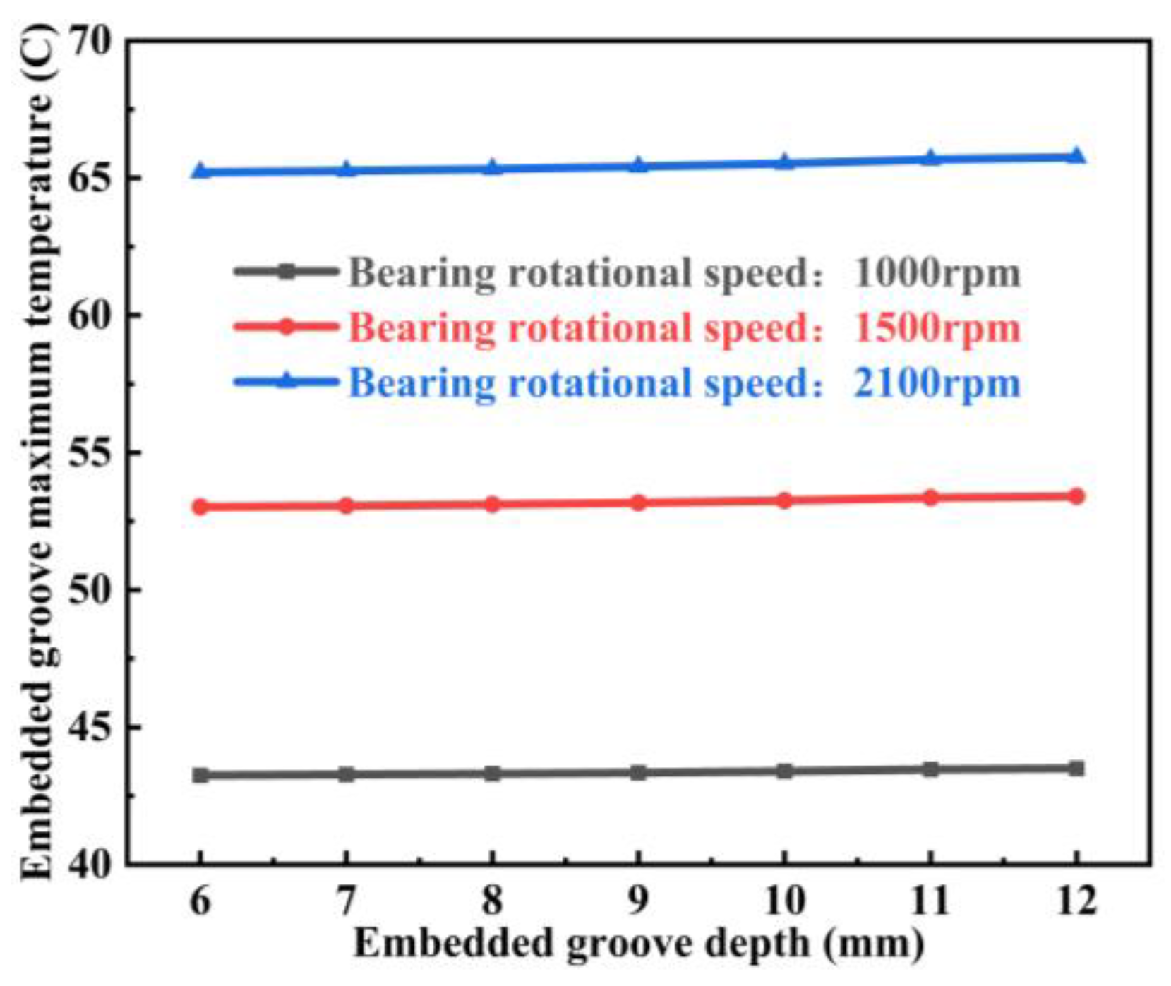
To evaluate the influence of train speed on the thermal response of the grooved outer ring, additional simulations were conducted under three typical operating velocities: 100 km/h, 250 km/h, and 350 km/h, corresponding to bearing rotational speeds of 1000 rpm, 1500 rpm, and 2100 rpm, respectively.
For each speed, groove depths ranging from 6 mm to 12 mm were analyzed with a fixed groove arc length of 45 mm and width of 20 mm. The corresponding frictional heat generation rates, calculated using the method described in Section 2.4, were 7468.80 W, 11,469.93 W, and 16,454.35 W, respectively.
Figure 13 shows the variation in maximum groove temperature with groove depth for different rotational speeds. As expected, the absolute temperature increased significantly with rotational speed due to higher frictional heat generation. The maximum temperature ranges were 43.25 °C to 43.50 °C (1000 rpm), 53.03 °C to 53.41 °C (1500 rpm), and 65.21 °C to 65.76 °C (2100 rpm), with maximum temperature differences among groove depths of 0.25 °C, 0.38 °C, and 0.55 °C, respectively.
Although the absolute temperature increased notably with speed, the relative distribution patterns and the trend of temperature rising with increasing groove depth remained consistent across all speeds. These results indicate that, within the examined range (100–350 km/h), train speed has a strong effect on absolute temperature but only a minor effect on the relative temperature distribution in the groove region, confirming the robustness of the conclusions obtained under the nominal speed condition.

5.6. Parametric Analysis of Temperature and Stress Response Due to Embedded Slot Geometry

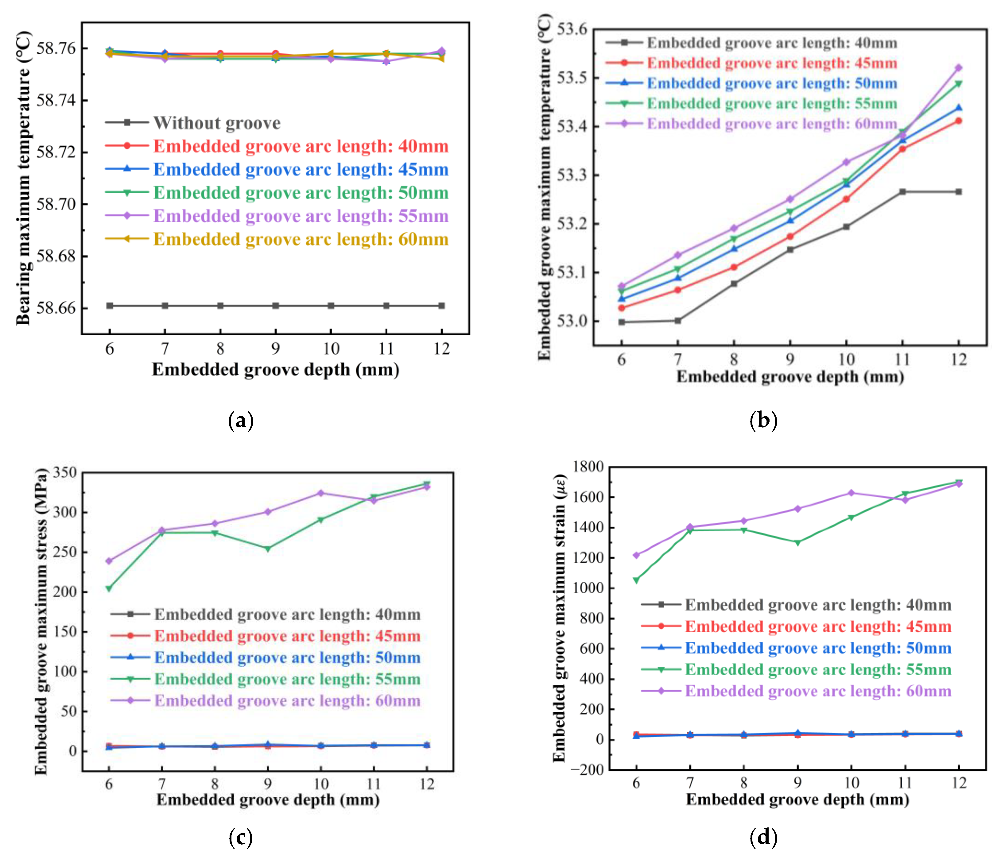
To comprehensively evaluate the effects of embedded groove design parameters on the temperature, stress, and thermal deformation responses of the axle box bearing, simulation results under different groove depth and arc length combinations were extracted. The trends of thermal–mechanical response metrics for the entire bearing and the groove region are plotted in Figure 14 and analyzed from two perspectives: global response and local disturbance.

5.6.1. Global Bearing Response Trends

Figure 14a presents the overall trend of the steady-state temperature of the bearing structure with varying design parameters, with the case without a groove included for comparison purposes. It can be observed that the variation in the overall bearing temperature is small, and the maximum temperature difference compared with the ungrooved case is less than 0.1 °C. The temperature rise remains within a reasonable range, indicating that the embedded groove has a limited influence on the overall thermal field of the bearing.

5.6.2. Local Disturbance Effects of Embedded Slot

Figure 14b–d present the trends of local steady-state temperature, maximum stress, and maximum thermal deformation in the groove region as the design parameters change:
  • Thermal response: temperature rises significantly with increasing groove depth and arc length, with evident thermal accumulation;
  • Stress response: maximum local stress increases markedly when the arc length reaches 55 mm and 60 mm, with stress concentrations forming at the groove edges;
  • Deformation response: as arc length increases to 55 mm and 60 mm, thermal deformation escalates rapidly, and asymmetric structures form on both sides of the groove, adversely affecting sensor encapsulation stability and adhesive reliability.
A comprehensive analysis of global and local thermo-mechanical responses indicates that a significant nonlinear jump occurs when the arc length reaches a certain value. Continued increases in groove depth and arc length result in rapid amplification of structural stress and thermal deformation.
Thermo-mechanical response analysis shows that increasing groove depth and arc length significantly amplify temperature, stress, and deformation. To balance sensor integration and structural reliability, it is necessary to make reasonable selections for parameters such as the depth and the arc length of the groove.

6. Conclusions

This study investigates the thermo-mechanical coupling response of sensor-embedded arc-shaped groove structures in an axle box double-row tapered roller bearing. By integrating contact mechanics theory, the Palmgren frictional heat model, and a multi-physics finite element method, the influence mechanisms of groove design parameters on the bearing’s temperature field, stress field, and thermo-mechanical coupling deformation were systematically analyzed. The main conclusions are as follows:
  • The errors between the proposed model and the theoretical analytical solutions for roller contact loads and contact stresses are both within 8%, verifying the accuracy and engineering applicability of the developed model;
  • Embedded groove structures significantly affect local thermo-mechanical responses. Increasing groove depth and arc length intensifies local thermal accumulation and stress concentration. Improper parameter combinations may lead to heat buildup and a rapid decline in local structural stiffness;
  • Considering thermal stability, stress control, and deformation uniformity, it is recommended to keep the groove depth within 6–9 mm and within a suitable arc length. This design range shows good coordination across all metrics and achieves a balanced trade-off between structural strength and sensor integration requirements, offering high overall performance.
The results of this study can provide theoretical support and engineering guidance for the structural optimization of intelligent embedded bearing systems in axle box applications, contributing to the enhancement of both operational safety and sensor integration efficiency. In the future study, the bearing temperature test and stress test will be conducted based on the reduced test bench to further verify the proposed model and laws.
The recommended groove parameter range of depth 6–9 mm and arc length 45–50 mm is based on the specific operating condition analyzed in this study, namely a radial load of 110 kN and an axial load of 50 kN. For other rotation speeds, load magnitudes, or load ratios, additional analysis may be required to verify or adjust these recommendations.
It should be noted that the present model considers only the steady-state thermo-mechanical response under service loads. The effects of impact loads and vibration excitations, which may accelerate the thermomechanical fatigue of the groove, are not included in the current analysis and will be addressed in future work.

Author Contributions

Conceptualization, L.W. and H.T.; methodology, L.W., C.H. and F.L.; formal analysis, C.H. and F.L.; investigation, L.W. and C.H.; resources, H.T.; data curation, F.L.; writing—original draft, C.H. and L.W.; writing—review and editing, L.W. and H.T.; visualization, F.L.; project administration, F.L.; funding acquisition, L.W. All authors have read and agreed to the published version of the manuscript.

Funding

This work was supported in part by the National Key R&D Program of China under Grant 2023YFB3406102, and in part by the Hunan Natural Science Foundation Project under Grant 2025JJ60317 and 2025JJ80228.

Data Availability Statement

Data is contained within the article.

Conflicts of Interest

The authors declare that they have no known competing financial interests or personal relationships that could have appeared to influence the work reported in this paper.

References

  1. Ali, A.; Permana, D.I.; Yudha, H.N. Analysis of variance dimension of reinforcement to stress concentration factor using finite element method. Sinergi 2022, 26, 295–302. [Google Scholar] [CrossRef]
  2. Xu, K.; Hu, H.; Guo, N.; Ma, X.Q.; Li, X.P. Research on temperature rise characteristics prediction of main shaft dual-Rotor rolling bearings in aircraft engines. Lubricants 2024, 12, 210. [Google Scholar] [CrossRef]
  3. Li, Z.J.; Zhao, C.Y. Thermal mechanics coupling analysis of angular contact ball bearings installed in pairs in feed system. China Mech. Eng. 2023, 34, 821–829. (In Chinese) [Google Scholar] [CrossRef]
  4. Zhang, S.; Zhang, Y.M.; Li, T.J. Thermal coupling simulation analysis of face-to-face tapered roller bearing device. Mach. Des. Manuf. 2025; 1–5, online first. (In Chinese) [Google Scholar] [CrossRef]
  5. Tang, R.; Cao, S.S.; Gao, L.X.; Li, G.L.; Deng, S.E. Thermal characteristics of angular contact ball bearings with two piece inner rings under thermodynamic coupling. Bearing 2024, 4, 7–17. (In Chinese) [Google Scholar] [CrossRef]
  6. Wang, M.; Yang, S.P.; Liu, Y.Q.; Chen, Y.H.; Zhang, K. Establishment of the thermo-mechanical coupling model of axle box bearings with track irregularity excitation and analysis of its temperature characteristics. Appl. Math. Mech. Engl. Ed. 2024, 45, 1965–1986. [Google Scholar] [CrossRef]
  7. Wang, B.S.; Liu, Y.Q.; Liao, Y.Y.; Wang, Y.X. Analysis of temperature characteristics of high-speed train wheelset system under complex operating conditions. Int. J. Mech. Syst. Dyn. 2024, 4, 331–345. [Google Scholar] [CrossRef]
  8. Yang, C.; Wu, X.W.; Chi, M.R.; Luo, Y.P.; Liang, S.L. Modelling and analysis of thermal characteristics of high-speed train axle box bearings considering vehicle-environment coupling effects. Int. J. Heat Mass Transf. 2024, 235, 126209. [Google Scholar] [CrossRef]
  9. Ma, Q.Y.; Liu, Y.Q.; Yang, S.P.; Liao, Y.Y.; Wang, B.S. A coupling model of high-speed train-axle box bearing and the vibration characteristics of bearing with defects under wheel rail excitation. Machines 2022, 10, 1024. [Google Scholar] [CrossRef]
  10. Chen, J.H.; Zhang, W.Y.; Wang, H. Intelligent bearing structure and temperature field analysis based on finite element simulation for sustainable and green manufacturing. J. Intell. Manuf. 2021, 32, 745–756. [Google Scholar] [CrossRef]
  11. Xue, Y.J.; Meng, F.J.; Yu, Y.J.; Cai, H.C. Thermal–mechanical coupling model of a double-piece inner ring ball bearing based on ADAMS secondary development. Lubricants 2025, 13, 154. [Google Scholar] [CrossRef]
  12. Liu, J.F.; Zhang, P. Thermo-mechanical behavior analysis of motorized spindle based on a coupled model. Adv. Mech. Eng. 2018, 10, 1–12. [Google Scholar] [CrossRef]
  13. Chang, Z.Y.; Hou, L.; Lin, R.Z.; Chen, Y.S.; Masarati, P. Monolithic approaches to transient thermo-mechanical interaction in nonlinear rotor systems. Int. J. Mech. Sci. 2025, 290, 110066. [Google Scholar] [CrossRef]
  14. Zhou, G.W.; Li, G.L.; Chen, P.; Hou, Y.; Wang, X. Research on the load distribution measurement of high-speed train axle box bearing. Part I: Simulation analysis of the notching method of bearing housing. J. Exp. Mech. 2022, 37, 18–26. (In Chinese) [Google Scholar] [CrossRef]
  15. Li, Z.; Chen, Q.; Wang, Q.J. Structural comparative analysis of different grooved spherical bearings based on finite element method. Lubr. Eng. 2019, 44, 72–80. (In Chinese) [Google Scholar] [CrossRef]
  16. Yang, G.L.; Huang, F.T.; Jin, J.; Wang, W.Y.; Wu, G.G. Numerical analysis of gear pump sliding bearing slot based on Matlab simulation. Hydraul. Pneum. Seals. 2020, 9, 21–24. (In Chinese) [Google Scholar] [CrossRef]
  17. Wang, D.D.; Wang, N.; Chen, Y.H.; Zhang, N.; Zhang, C.M. Mechanism analysis of the influence of slotting on deformation of embedded water-lubricated bearing. J. Shaanxi Univ. Technol. (Nat. Sci. Ed.). 2024, 28, 445–453. (In Chinese) [Google Scholar] [CrossRef]
  18. Gutarevich, V.O.; Martyushev, N.V.; Klyuev, R.V.; Kukartsev, V.A.; Kukartsev, V.V.; Iushkova, L.V.; Korpacheva, L.N. Reducing Oscillations in Suspension of Mine Monorail Track. Appl. Sci. 2023, 13, 4671. [Google Scholar] [CrossRef]
  19. Wu, Q.X.; Zhuang, Y.T. Discussion on insertion slot for housings of insert bearings. Bearing 2019, 1, 20–22. (In Chinese) [Google Scholar] [CrossRef]
  20. Luan, W.L.; Wang, Y.D.; Wang, H.M.; Liu, Y.; Li, X.L.; Xu, F.C. Theoretical analysis on the impact of spiral groove structural parameters on static characteristics of novel hybrid gas foil thrust bearing with spiral grooves. J. Mech. Eng. 2025, 61, 358–371. [Google Scholar]
  21. Fesanghary, M.; Khonsari, M.M. On the optimum groove shapes for load-carrying capacity enhancement in parallel flat surface bearings: Theory and experiment. Tribol. Int. 2013, 67, 254–262. [Google Scholar] [CrossRef]
  22. Brito, F.P.; Miranda, A.S.; Fillon, M. Analysis of the effect of grooves in single and twin axial groove journal bearings under varying load direction. Tribol. Int. 2016, 103, 609–619. [Google Scholar] [CrossRef]
  23. Xu, M.Y.; Chen, W. Study on the performance of liquid metal lubricated V-groove bearing considering turbulence. Appl. Sci. 2021, 11, 940. [Google Scholar] [CrossRef]
  24. Zhang, X.Y.; Liu, C.P.; Zhao, B. An optimization research on groove textures of a journal bearing using particle swarm optimization algorithm. Mech. Ind. 2021, 22, 1. [Google Scholar] [CrossRef]
  25. Bättig, P.K.; Wagner, P.H.; Schiffmann, J.A. Experimental investigation of enhanced grooves for herringbone grooved journal bearings. J. Tribol. 2022, 144, 091801. [Google Scholar] [CrossRef]
  26. Wang, L.K.; Hu, C.; Hu, L.; Liu, F.Y.; Tang, H.B. An investigation on the mechanical characteristics of railway locomotive axle box bearings with sensor-embedded slots. Machines 2025, 13, 358. [Google Scholar] [CrossRef]
  27. Deng, S.E.; Jia, Q.Y. Design Principles of Rolling Bearings, 1st ed.; China Standard Press: Beijing, China, 2008; pp. 127–130. [Google Scholar]
  28. Tao, W.Q. Heat Transfer, 5th ed.; Higher Education Press: Beijing, China, 2019. [Google Scholar]
  29. Wang, J.W.; Su, J.; Meng, Z.Z.; Kouediatouka, A.N.; Jiang, S.; Zheng, J.X.; Dong, G.N. Entrance process and interface distribution of nanoparticles in point contact. Tribol. Int. 2024, 200, 110085. [Google Scholar] [CrossRef]
  30. Burton, R.A.; Staph, H.E. Thermally activated seizure of angular contact bearings. Tribol. Trans. 2008, 10, 408–417. [Google Scholar] [CrossRef]
  31. Li, J.N.; Xue, J.F.; Ma, Z.T. Study on the thermal distribution characteristics of high-speed and light-load rolling bearing considering skidding. Appl. Sci. 2018, 8, 1593. [Google Scholar] [CrossRef]
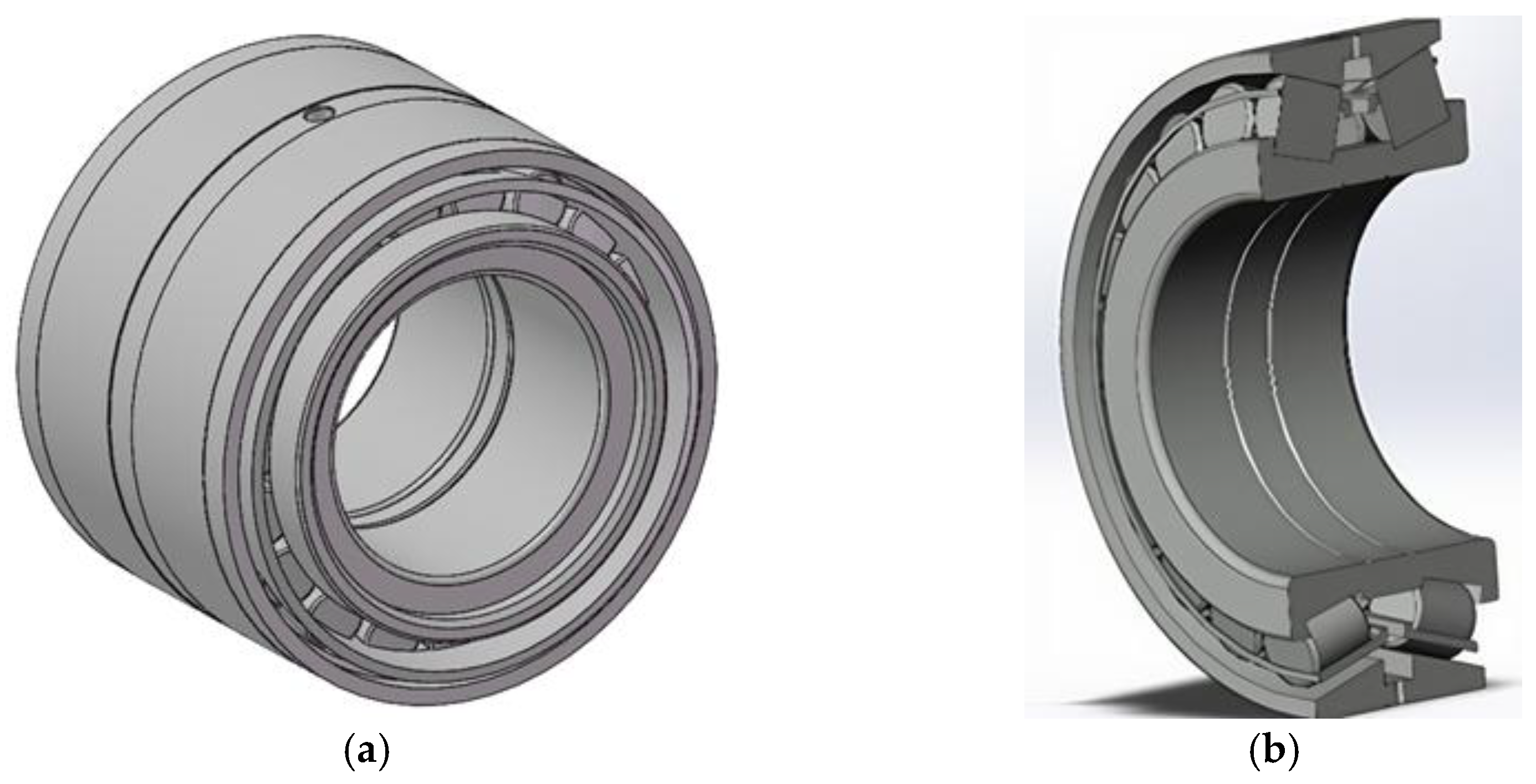
Figure 1. Geometric model of the axle-box bearing: (a) Overall assembly model; (b) Cutaway view showing internal components including the inner and outer rings, rollers, and cage.
Symmetry 17 01667 g001
Figure 2. A bearing model with an embedded slot.
Symmetry 17 01667 g002
Figure 3. Slice partitioning and roller numbering for the axle box bearing.
Symmetry 17 01667 g003
Figure 4. Contact definitions in the bearing model.
Symmetry 17 01667 g004
Figure 5. Mesh generation for the bearing components.
Symmetry 17 01667 g005
Figure 6. Boundary and loading conditions of the model.
Symmetry 17 01667 g006
Figure 7. Comparison and error analysis of contact loads for each roller in the bearing.
Symmetry 17 01667 g007
Figure 8. Comparison and error analysis of contact stresses for each roller in the bearing.
Symmetry 17 01667 g008
Figure 9. Mesh independence analysis of contact pressure.
Symmetry 17 01667 g009
Figure 10. Temperature distribution contours of embedded slots under different design parameters.
Symmetry 17 01667 g010
Figure 11. Equivalent stress contours under different embedded slot parameters.
Symmetry 17 01667 g011
Figure 12. Temperature under different ambient temperatures and groove depths.
Symmetry 17 01667 g012
Figure 13. Temperature under different bearing rotational speeds and groove depths.
Symmetry 17 01667 g013
Figure 14. Simulation results of the bearing and embedded slot under different design parameters: (a) Effect of embedded groove depth on the maximum bearing temperature under different groove arc lengths and the case without groove; (b) Effect of embedded groove depth on the maximum groove temperature under different groove arc lengths; (c) Effect of embedded groove depth on the maximum groove stress under different groove arc lengths; (d) Effect of embedded groove depth on the maximum groove strain under different groove arc lengths.
Symmetry 17 01667 g014
Table 1. Structural dimensions of the bearing.
No.ParameterValue
1Outer ring diameter 240 0.076 0.004 mm
2Inner ring diameter 130 0.039 0.014 mm
3Small end diameter of roller 24.46 0.006 + 0.000 mm
4Large end diameter of roller 26.67 0.006 + 0.000 mm
5Outer contact angle10.00°
6Inner contact angle7.57°
7Half cone angle1.215°
8Effective contact length52.04 mm
9Number of rollers38
Disclaimer/Publisher’s Note: The statements, opinions and data contained in all publications are solely those of the individual author(s) and contributor(s) and not of MDPI and/or the editor(s). MDPI and/or the editor(s) disclaim responsibility for any injury to people or property resulting from any ideas, methods, instructions or products referred to in the content.