
Multi-Scale Feature Enhancement Method for Underwater Object Detection

Abstract
1. Introduction
- Image-blurring issue: The absorption and scattering of light by the water typically lead to a rapid reduction in light intensity. Under normal optical mechanisms, insufficient light can cause image darkening and color deviation. Additionally, the fluctuation and turbidity of a water body can further worsen the distortion of image features. For instance, unclear water will result in warped or blurry shapes of the target.
- Dense small target issue: The large-scale aggregation of some aquatic organisms often triggers the dense detection issue of small targets. For instance, the aggregation of small-size fishes can make it difficult for detection models to distinguish individual targets, resulting in false positive and false negative phenomena.
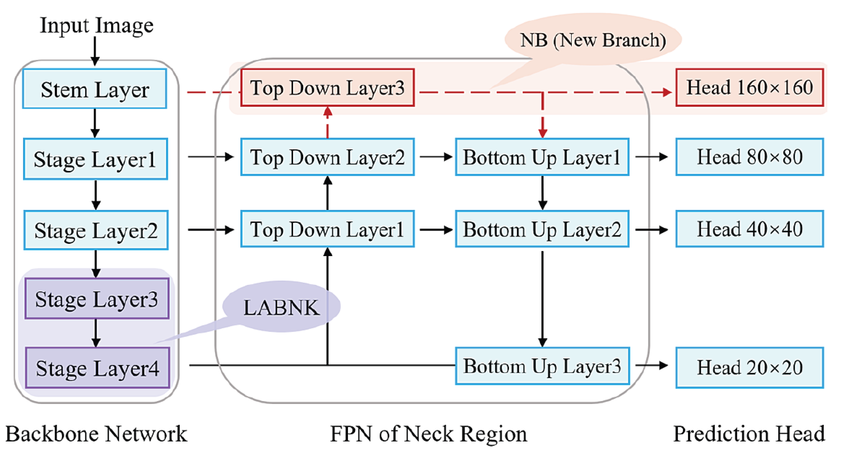
- For the image blurring issue. It conducts a multi-scale local awareness operation to enhance the information integration ability of the basic C2F module in the Backbone network. To be specific, anchoring the BNK submodule in C2F, the multi-scale design adopts symmetric local awareness operations to overcome the feature vanishing or weakening phenomenon during the feature extraction. The ‘Stage Layer 3’ and ‘Stage Layer 4’ in Figure 1 denote its locations.
- For the dense small target issue. Following the multi-scale information integration mechanism of FPN between deep and shallow features. It extra injects a shallow branch into the FPN to supply large-scale features for subsequent prediction. This idea is mainly supported by the fact that shallow features usually carry rich, detailed information. The ‘Top Down Layer3’ and ‘- -’ in Figure 1 show this design. Formally, this idea can be viewed as an enhancement of normal FPN structure.
2. Related Work
2.1. Deep-Learning-Based Object Detection (DLOD) Methods
2.2. Underwater Object Detection Algorithms
3. Methodology
3.1. Overview of the MSFE Method
3.2. The Structural Design of C2F Module
3.2.1. Introduction of the Initial C2F Module
- (1)
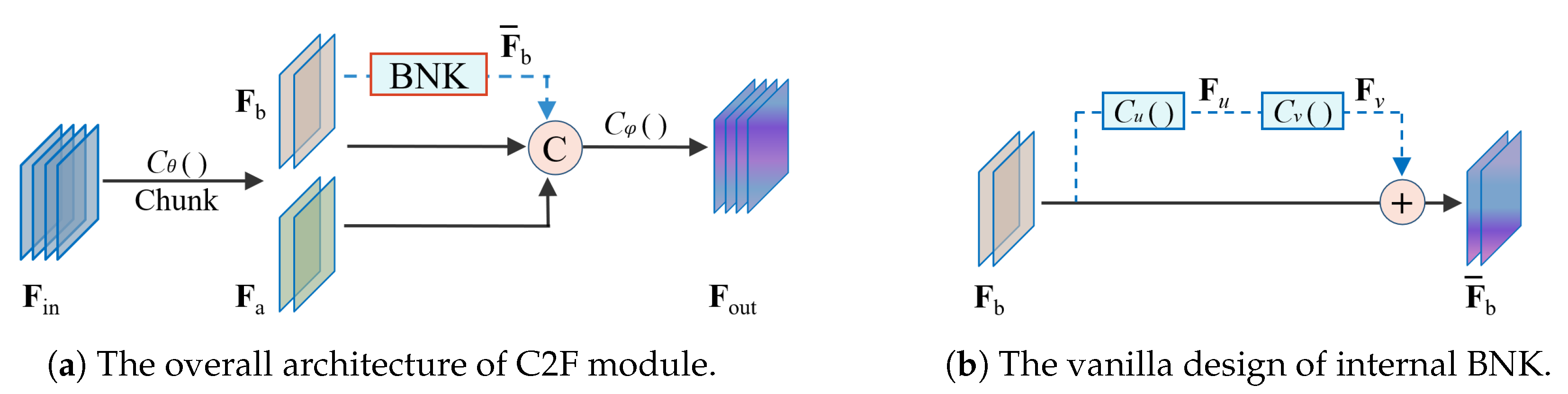
- The overall architecture of the C2F module
- (2)
- The initial BNK submodule in C2F
3.2.2. The Design of the Local Awareness BNK (LABNK)
- (1)
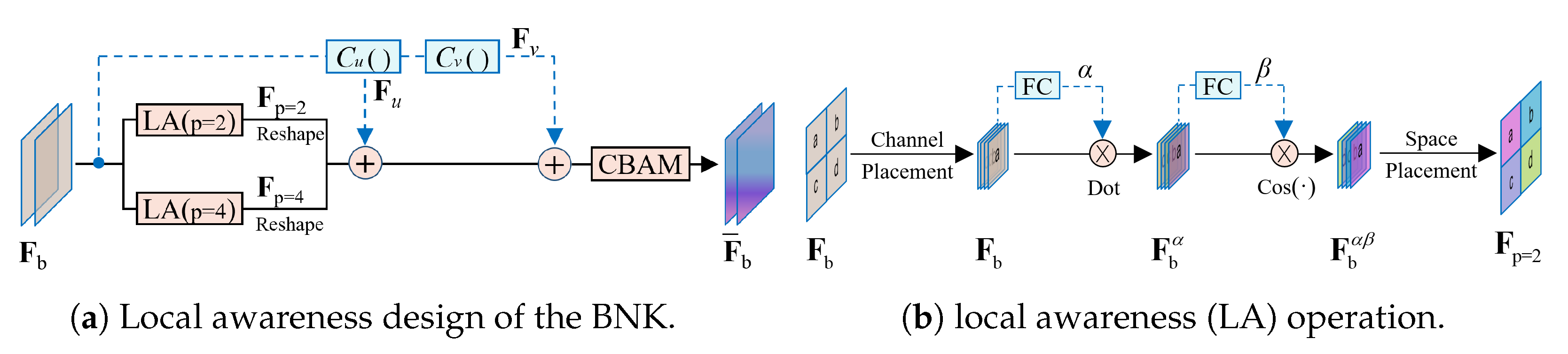
- The overall architecture of the LABNK module
- (2)
- The internal operation of the local awareness (LA) module
3.3. Small Receptive Field Detection Layer
3.4. Loss Function
3.5. Effect Validation of the Two Structural Components
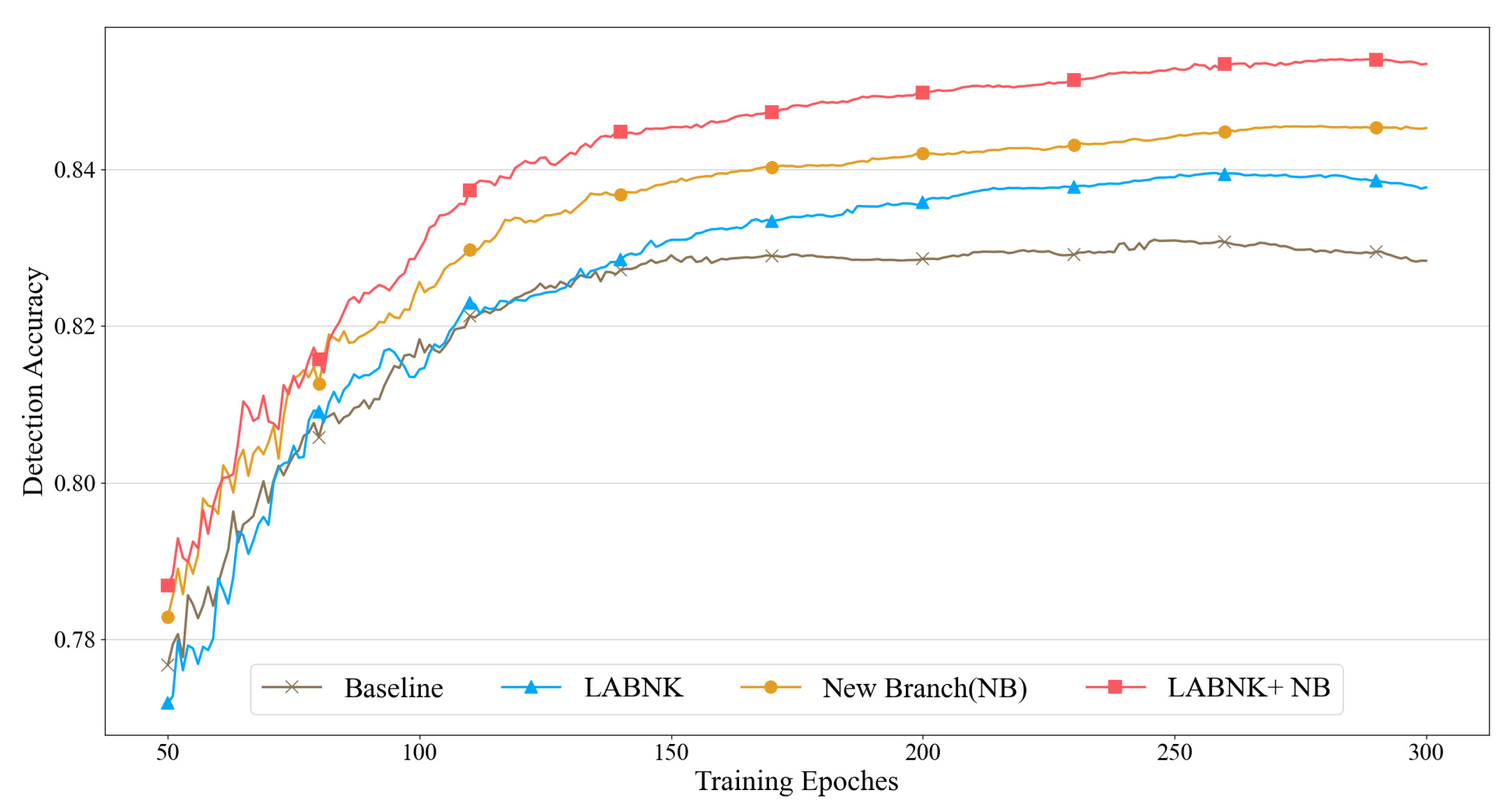
- The individual validation of LABNK and New Branch: For the LABNK, its positive effect on performance improvement becomes gradually apparent after 150 iterations. In contrast, the additional shallow branch yields noticeable improvements as early as the 50th epoch. In summary, the trend of test performance trend in Figure 4 indicates that both operations can significantly enhance the detection accuracy of the model.
- The collaborative validation of LABNK and New Branch: In contrast to the baseline method, the combination of the two operations (LABNK + NB) shows a more positive effect from the 80th epoch. This indicates that there is no conflict between the two operations. Furthermore, we can see that their functional overlap is not significant. For example, taking the NB method as the baseline, the combined setting provides a greater accuracy advantage across the entire training process. One main reason is that both operation items perform multi-scale feature enhancement at different levels. The LABNK focuses more on fine-grained operations within the convolutional module. In contrast, the NB emphasizes the feature fusion mechanism across different layers.
4. Experiments
4.1. Underwater Object Detection Datasets
4.2. Experimental Setting
4.3. Ablation Study on the DUO Dataset
- In terms of AP for each identity: The individual use of both components, compared to the baseline method, yields a positive effect, with the NB component achieving better results in detecting holothurian. Additionally, the combination of two components also demonstrates a slight advantage in accuracy for some identities, except for holothurian. This suggests that the combined approach may not provide a universal improvement across all identities.
- In terms of comprehensive performance: Based on mAP(50) and mAP(50:95), the individual use of the two components has resulted in improving performance compared to the baseline model, as shown in Table 3. Furthermore, compared to using LABNK and NB as individual benchmarks, the combination of both components achieves the greatest improvement. This is primarily due to the synergistic effect of the two multi-scale feature enhancement operations.
4.4. Visualization Validation
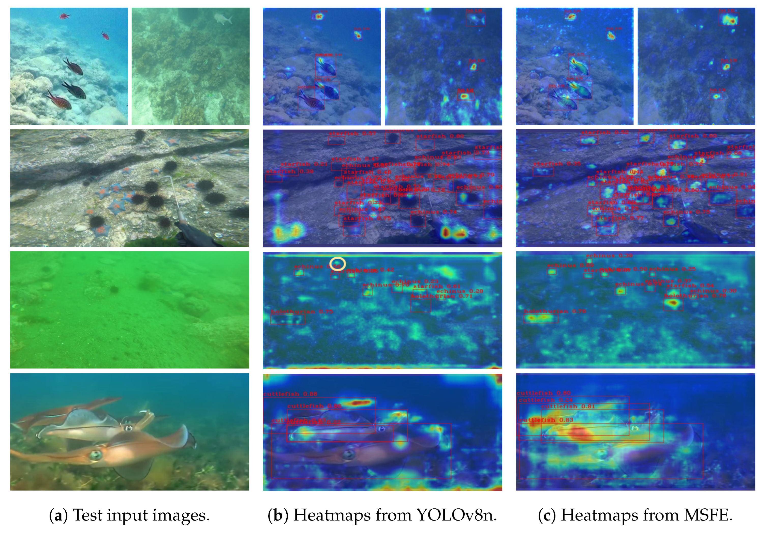
4.4.1. Comparative Validation in Blurry Scenario
- Small-sized targets: (i) Normal background: Taking the three images in the first and second rows as references, the baseline model (YOLOv8n) often exhibits insufficient attention to the target, which clearly increases the risk of missed detections. In contrast, with the support of LABNK and NB, the MSFE method demonstrates a stronger attention intensity on small-sized targets. In addition, it reduces unnecessary attention on non-target regions in terms of attention breadth. (ii) Weak background-target differentiation: In the third row, both models exhibit fuzzy attention regions. However, we can find that the MSFE method provides a clearer distinction between the background and target regions. For instance, the YOLOv8n fails to detect the sea urchin target (highlighted by the yellow circular annotation in the middle image).
- Large-sized targets: For the large-sized targets with occlusion, taking the cuttlefish instance in the fourth row as the reference, the baseline model shows insufficient attention to the target region, which may lead to difficulty in clearly identifying the boundary information of different target instances. In contrast, the MSFE provides a more comprehensive assessment of the target region. In this case, the sufficient attention supply is beneficial for acquiring the target’s boundary information.
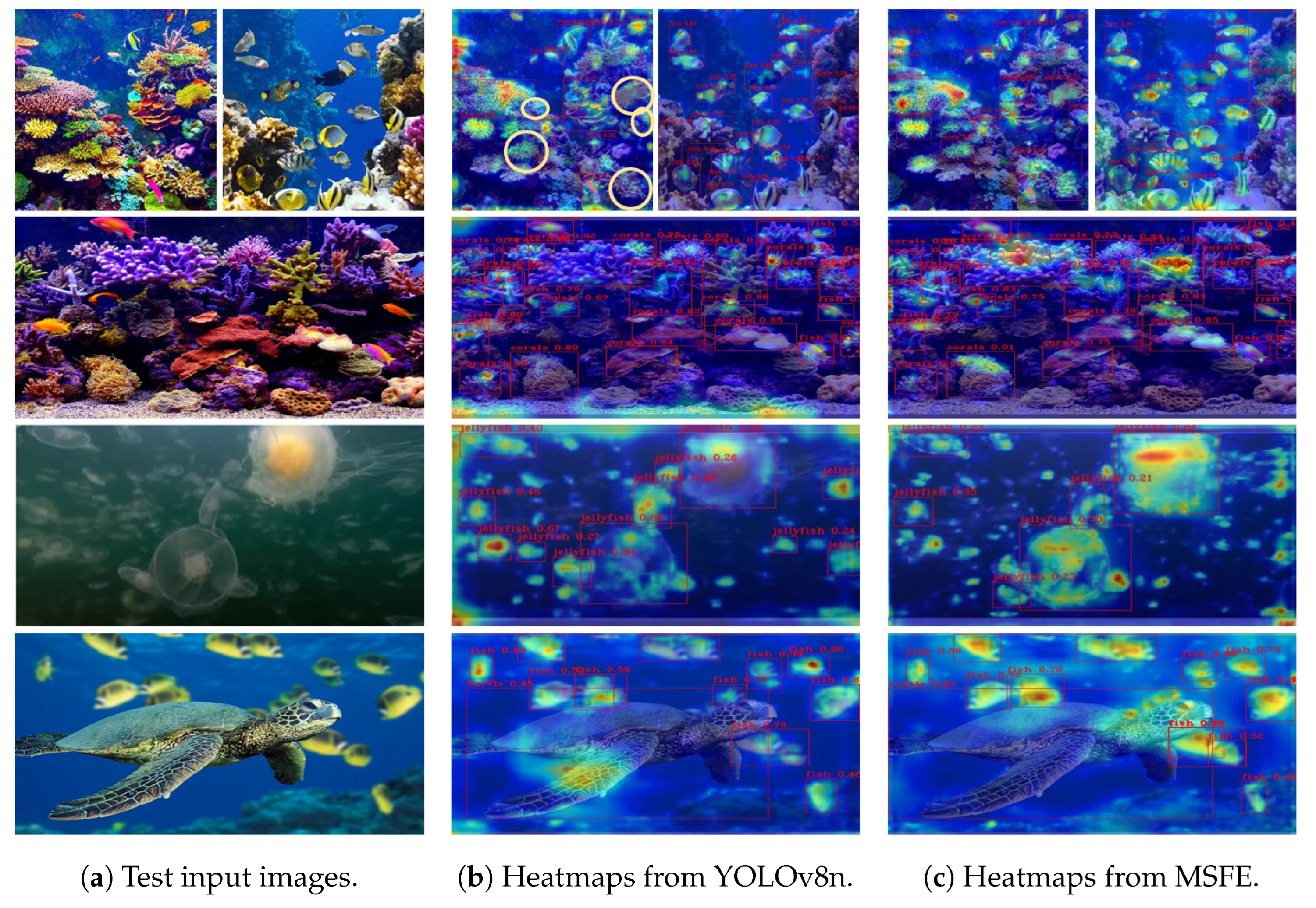
4.4.2. The Comparative Validation in Dense Scenario
- Non-multi-scale situation: Referring to the images in the first two rows, the initial YOLOv8n shows weak attention on the target, similar to the situation shown in Figure 5. To confirm this case, the missed and false detection targets are specifically annotated in the third image of the first row (highlighted by the yellow circular annotations). In contrast, the MSFE method shows much stronger attention on the target.
- Multi-scale situation: Taking the images in the third and fourth rows as examples, when there are large scale (size) differences between different targets, the MSFE clearly demonstrates a more global capture of the feature information of large-sized targets. For instance, the MSFE performs a more comprehensive feature assessment for the key head region of a large-sized jellyfish target, which evidently enhances the model’s generalization capability when dealing with multi-scale target instances.
4.5. General Comparison on the DUO Dataset
- In terms of accuracy metrics: The MSFE exhibits a more notable advantage over other methods in both mAP(50) and mAP(50:95) metrics. In contrast to the baseline method (YOLOv8n), it achieves an accuracy improvement of 2.4%. Compared to the recent underwater detection method (YOLOv7-CHS) in 2023, it also achieves an accuracy gain of approximately 1.0%. It is worth mentioning that the report of the MSFE method is built upon the lightweight YOLOv8n model. Therefore, it has the potential to achieve higher accuracy when applied to other large models.
- In terms of other metrics: The MSFE method shows a slight trade-off trouble between accuracy and efficiency. To be specific, for the benchmark YOLOv8n model, the auxiliary modification results in an increase of in parameters and an additional computational cost of in FLOPs. In this case, other conventional small models without a specific design for underwater object detection demonstrate better detection efficiency, such as the YOLOv5n, YOLOv6n, YOLOX-nano, and YOLOv9t.
4.6. Comprehensive Performance Comparison Based on RUOD Dataset
- In terms of accuracy metrics: In contrast to reports on the DUO dataset, all methods show a decline in test accuracy on the RUOD dataset. One possible reason is that the RUOD dataset contains 10 identities, making it more challenging than the DUO dataset, which has only 4 identities. To check the effect of MSFE, we observe that it gains similar improvements for the YOLOv8n. Moreover, it achieves an accuracy gain of about 1.5–2.0% over the best YOLOv9t in terms of mAP(50) and mAP(50:95). This further highlights its positive effect in handling underwater blurry images.
- In terms of other metrics: Taking small YOLO models as the baseline, the MSFE method exhibits similar disadvantages to the situation on the DUO dataset in terms of parameter count, computational cost, and detection time. The main reason is that the MSFE injects an additional LA module and a new feature branch into the initial BNK module and FPN, respectively. This drawback further gives rise to the disadvantages in terms of FLOPs and detection time. Fortunately, the MSFE method still maintains a certain efficiency advantage over other underwater detection methods. This is due to the fact that earlier methods inherently employed larger models.
5. Conclusions
Author Contributions
Funding
Data Availability Statement
Conflicts of Interest
References
- Zhao, M.; Zhou, H.; Li, X. YOLOv7-SN: Underwater Target Detection Algorithm Based on Improved YOLOv7. Symmetry 2024, 16, 514. [Google Scholar] [CrossRef]
- Viola, P.; Jones, M. Rapid object detection using a boosted cascade of simple features. In Proceedings of the 2001 IEEE Computer Society Conference on Computer Vision and Pattern Recognition, CVPR 2001, Kauai, HI, USA, 8–14 December 2001; IEEE: Piscataway, NJ, USA, 2001; Volume 1, p. I. [Google Scholar]
- Dalal, N.; Triggs, B. Histograms of oriented gradients for human detection. In Proceedings of the 2005 IEEE Computer Society Conference on Computer Vision and Pattern Recognition (CVPR’05), San Diego, CA, USA, 20–25 June 2005; IEEE: Piscataway, NJ, USA, 2005; Volume 1, pp. 886–893. [Google Scholar]
- Felzenszwalb, P.; McAllester, D.; Ramanan, D. A discriminatively trained, multiscale, deformable part model. In Proceedings of the 2008 IEEE Conference on Computer Vision and Pattern Recognition, Anchorage, AK, USA, 23–28 June 2008; IEEE: Piscataway, NJ, USA, 2008; pp. 1–8. [Google Scholar]
- Chen, X.; Chen, H. A novel color edge detection algorithm in RGB color space. In Proceedings of the IEEE 10th International Conference On Signal Processing Proceedings, Beijing, China, 24–28 October 2010; IEEE: Piscataway, NJ, USA, 2010; pp. 793–796. [Google Scholar]
- Beijbom, O.; Edmunds, P.J.; Kline, D.I.; Mitchell, B.G.; Kriegman, D. Automated annotation of coral reef survey images. In Proceedings of the 2012 IEEE Conference on Computer Vision and Pattern Recognition, Providence, RI, USA, 16–21 June 2012; IEEE: Piscataway, NJ, USA, 2012; pp. 1170–1177. [Google Scholar]
- Nagaraja, S.; Prabhakar, C.; Kumar, P.P. Extraction of texture based features of underwater images using RLBP descriptor. In Proceedings of the 3rd International Conference on Frontiers of Intelligent Computing: Theory and Applications (FICTA) 2014, Bhubaneswar, India, 14–15 November 2014; Springer: Berlin/Heidelberg, Germany, 2015; Volume 2, pp. 263–272. [Google Scholar]
- Fatan, M.; Daliri, M.R.; Shahri, A.M. Underwater cable detection in the images using edge classification based on texture information. Measurement 2016, 91, 309–317. [Google Scholar] [CrossRef]
- Srividhya, K.; Ramya, M. Accurate object recognition in the underwater images using learning algorithms and texture features. Multimed. Tools Appl. 2017, 76, 25679–25695. [Google Scholar] [CrossRef]
- Shi, X.; Huang, H.; Wang, B.; Pang, S.; Qin, H. Underwater cage boundary detection based on GLCM features by using SVM classifier. In Proceedings of the 2019 IEEE/ASME International Conference on Advanced Intelligent Mechatronics (AIM), Hong Kong, China, 8–12 July 2019; IEEE: Piscataway, NJ, USA, 2019; pp. 1169–1174. [Google Scholar]
- Bazeille, S.; Quidu, I.; Jaulin, L. Color-based underwater object recognition using water light attenuation. Intell. Serv. Robot. 2012, 5, 109–118. [Google Scholar] [CrossRef]
- Hou, G.J.; Luan, X.; Song, D.L.; Ma, X.Y. Underwater man-made object recognition on the basis of color and shape features. J. Coast. Res. 2016, 32, 1135–1141. [Google Scholar] [CrossRef]
- Cheng, E.; Lin, X.; Chen, Y.; Yuan, F.; Yang, W. GLCM Based No-Reference Perceptual Blur Metric For Underwater Blur Image. Int. J. Circuits Syst. Signal Process. 2016, 10, 291–296. [Google Scholar]
- Chen, Z.; Zhang, Z.; Dai, F.; Bu, Y.; Wang, H. Monocular vision-based underwater object detection. Sensors 2017, 17, 1784. [Google Scholar] [CrossRef]
- Vasamsetti, S.; Setia, S.; Mittal, N.; Sardana, H.K.; Babbar, G. Automatic underwater moving object detection using multi-feature integration framework in complex backgrounds. IET Comput. Vis. 2018, 12, 770–778. [Google Scholar] [CrossRef]
- Girshick, R.; Donahue, J.; Darrell, T.; Malik, J. Rich feature hierarchies for accurate object detection and semantic segmentation. In Proceedings of the IEEE Conference on Computer Vision and Pattern Recognition, Columbus, OH, USA, 23–28 June 2014; pp. 580–587. [Google Scholar]
- Girshick, R. Fast r-cnn. arXiv 2015, arXiv:1504.08083. [Google Scholar]
- Ren, S.; He, K.; Girshick, R.; Sun, J. Faster R-CNN: Towards real-time object detection with region proposal networks. IEEE Trans. Pattern Anal. Mach. Intell. 2016, 39, 1137–1149. [Google Scholar] [CrossRef]
- He, K.; Gkioxari, G.; Dollár, P.; Girshick, R. Mask r-cnn. In Proceedings of the IEEE International Conference on Computer Vision, Venice, Italy, 22–29 October 2017; pp. 2961–2969. [Google Scholar]
- Redmon, J. You only look once: Unified, real-time object detection. In Proceedings of the IEEE Conference on Computer Vision and Pattern Recognition, Las Vegas, NV, USA, 27–30 June 2016. [Google Scholar]
- Redmon, J.; Farhadi, A. YOLO9000: Better, faster, stronger. In Proceedings of the IEEE Conference on Computer Vision and Pattern Recognition, Honolulu, HI, USA, 21–26 July 2017; pp. 7263–7271. [Google Scholar]
- Ge, Z. Yolox: Exceeding yolo series in 2021. arXiv 2021, arXiv:2107.08430. [Google Scholar]
- Li, C.; Li, L.; Jiang, H.; Weng, K.; Geng, Y.; Li, L.; Ke, Z.; Li, Q.; Cheng, M.; Nie, W.; et al. YOLOv6: A single-stage object detection framework for industrial applications. arXiv 2022, arXiv:2209.02976. [Google Scholar]
- Wang, C.Y.; Bochkovskiy, A.; Liao, H.Y.M. YOLOv7: Trainable bag-of-freebies sets new state-of-the-art for real-time object detectors. In Proceedings of the IEEE/CVF Conference on Computer Vision and Pattern Recognition, Vancouver, BC, Canada, 17–24 June 2023; pp. 7464–7475. [Google Scholar]
- Ultralytics. YOLOv8. 2023. Available online: https://github.com/ultralytics/ultralytics (accessed on 1 November 2024).
- Wang, C.Y.; Yeh, I.H.; Mark Liao, H.Y. Yolov9: Learning what you want to learn using programmable gradient information. In Proceedings of the European Conference on Computer Vision, Milan, Italy, 29 September–4 October 2024; Springer: Berlin/Heidelberg, Germany, 2024; pp. 1–21. [Google Scholar]
- Chen, L.; Huang, Y.; Dong, J.; Xu, Q.; Kwong, S.; Lu, H.; Lu, H.; Li, C. Underwater Object Detection in the Era of Artificial Intelligence: Current, Challenge, and Future. arXiv 2024, arXiv:2410.05577. [Google Scholar]
- Cong, X.; Zhao, Y.; Gui, J.; Hou, J.; Tao, D. A Comprehensive Survey on Underwater Image Enhancement Based on Deep Learning. arXiv 2024, arXiv:2405.19684. [Google Scholar]
- Xu, S.; Zhang, M.; Song, W.; Mei, H.; He, Q.; Liotta, A. A systematic review and analysis of deep learning-based underwater object detection. Neurocomputing 2023, 527, 204–232. [Google Scholar] [CrossRef]
- Jian, M.; Yang, N.; Tao, C.; Zhi, H.; Luo, H. Underwater object detection and datasets: A survey. Intell. Mar. Technol. Syst. 2024, 2, 9. [Google Scholar] [CrossRef]
- Liu, C.; Shu, X.; Xu, D.; Shi, J. GCCF: A lightweight and scalable network for underwater image enhancement. Eng. Appl. Artif. Intell. 2024, 128, 107462. [Google Scholar] [CrossRef]
- Zhang, X.; Fang, X.; Pan, M.; Yuan, L.; Zhang, Y.; Yuan, M.; Lv, S.; Yu, H. A marine organism detection framework based on the joint optimization of image enhancement and object detection. Sensors 2021, 21, 7205. [Google Scholar] [CrossRef]
- Han, F.; Yao, J.; Zhu, H.; Wang, C. Underwater image processing and object detection based on deep CNN method. J. Sens. 2020, 2020, 6707328. [Google Scholar] [CrossRef]
- Ji, W.; Peng, J.; Xu, B.; Zhang, T. Real-time detection of underwater river crab based on multi-scale pyramid fusion image enhancement and MobileCenterNet model. Comput. Electron. Agric. 2023, 204, 107522. [Google Scholar] [CrossRef]
- Liu, Q.; Huang, W.; Duan, X.; Wei, J.; Hu, T.; Yu, J.; Huang, J. DSW-YOLOv8n: A new underwater target detection algorithm based on improved YOLOv8n. Electronics 2023, 12, 3892. [Google Scholar] [CrossRef]
- Zhao, S.; Zheng, J.; Sun, S.; Zhang, L. An improved YOLO algorithm for fast and accurate underwater object detection. Symmetry 2022, 14, 1669. [Google Scholar] [CrossRef]
- Feng, J.; Jin, T. CEH-YOLO: A composite enhanced YOLO-based model for underwater object detection. Ecol. Inform. 2024, 82, 102758. [Google Scholar] [CrossRef]
- Shen, X.; Sun, X.; Wang, H.; Fu, X. Multi-dimensional, multi-functional and multi-level attention in YOLO for underwater object detection. Neural Comput. Appl. 2023, 35, 19935–19960. [Google Scholar] [CrossRef]
- Zhou, Z.; Hu, Y.; Yang, X.; Yang, J. YOLO-based marine organism detection using two-terminal attention mechanism and difficult-sample resampling. Appl. Soft Comput. 2024, 153, 111291. [Google Scholar] [CrossRef]
- Cai, Z.; Vasconcelos, N. Cascade r-cnn: Delving into high quality object detection. In Proceedings of the IEEE conference on computer vision and pattern recognition, Salt Lake City, UT, USA, 18–23 June 2018; pp. 6154–6162. [Google Scholar]
- Farhadi, A.; Redmon, J. Yolov3: An incremental improvement. In Proceedings of the Computer Vision and Pattern Recognition, Salt Lake City, UT, USA, 18–23 June 2018; Springer: Berlin/Heidelberg, Germany, 2018; Volume 1804, pp. 1–6. [Google Scholar]
- Bochkovskiy, A.; Wang, C.Y.; Liao, H.Y.M. Yolov4: Optimal speed and accuracy of object detection. arXiv 2020, arXiv:2004.10934. [Google Scholar]
- Liu, W.; Anguelov, D.; Erhan, D.; Szegedy, C.; Reed, S.; Fu, C.Y.; Berg, A.C. Ssd: Single shot multibox detector. In Proceedings of the Computer Vision–ECCV 2016: 14th European Conference, Amsterdam, The Netherlands, 11–14 October 2016; Proceedings, Part I 14. Springer: Berlin/Heidelberg, Germany, 2016; pp. 21–37. [Google Scholar]
- Cheng, S.; Wang, Z.; Liu, S.; Han, Y.; Sun, P.; Li, J. Attention-Based Lightweight YOLOv8 Underwater Target Recognition Algorithm. Sensors 2024, 24, 7640. [Google Scholar] [CrossRef]
- Song, P.; Li, P.; Dai, L.; Wang, T.; Chen, Z. Boosting R-CNN: Reweighting R-CNN samples by RPN’s error for underwater object detection. Neurocomputing 2023, 530, 150–164. [Google Scholar] [CrossRef]
- Wang, H.; Xiao, N. Underwater object detection method based on improved faster RCNN. Appl. Sci. 2023, 13, 2746. [Google Scholar] [CrossRef]
- Chen, L.; Liu, Z.; Tong, L.; Jiang, Z.; Wang, S.; Dong, J.; Zhou, H. Underwater object detection using Invert Multi-Class Adaboost with deep learning. In Proceedings of the 2020 International Joint Conference on Neural Networks (IJCNN), Glasgow, UK, 19–24 July 2020; IEEE: Piscataway, NJ, USA, 2020; pp. 1–8. [Google Scholar]
- Liu, H.; Song, P.; Ding, R. Towards domain generalization in underwater object detection. In Proceedings of the 2020 IEEE International Conference on Image Processing (ICIP), Abu Dhabi, United Arab Emirates, 25–28 October 2020; IEEE: Piscataway, NJ, USA, 2020; pp. 1971–1975. [Google Scholar]
- Gao, J.; Zhang, Y.; Geng, X.; Tang, H.; Bhatti, U.A. PE-Transformer: Path enhanced transformer for improving underwater object detection. Expert Syst. Appl. 2024, 246, 123253. [Google Scholar] [CrossRef]
- Ji, X.; Chen, S.; Hao, L.Y.; Zhou, J.; Chen, L. FBDPN: CNN-Transformer hybrid feature boosting and differential pyramid network for underwater object detection. Expert Syst. Appl. 2024, 256, 124978. [Google Scholar] [CrossRef]
- Xu, S.; Zheng, S.; Xu, W.; Xu, R.; Wang, C.; Zhang, J.; Teng, X.; Li, A.; Guo, L. HCF-Net: Hierarchical Context Fusion Network for Infrared Small Object Detection. In Proceedings of the 2024 IEEE International Conference on Multimedia and Expo (ICME), Niagara Falls, ON, Canada, 15–19 July 2024. [Google Scholar]
- Woo, S.; Park, J.; Lee, J.Y.; Kweon, I.S. Cbam: Convolutional block attention module. In Proceedings of the European Conference on Computer Vision (ECCV), Tel Aviv, Israel, 23–27 October 2018; pp. 3–19. [Google Scholar]
- Hu, J.; Shen, L.; Sun, G. Squeeze-and-excitation networks. In Proceedings of the IEEE Conference on Computer Vision and Pattern Recognition, Salt Lake City, UT, USA, 18–23 June 2018; pp. 7132–7141. [Google Scholar]
- Lin, T.Y.; Dollár, P.; Girshick, R.; He, K.; Hariharan, B.; Belongie, S. Feature pyramid networks for object detection. In Proceedings of the IEEE Conference on Computer Vision and Pattern Recognition, Honolulu, HI, USA, 21–26 July 2017; pp. 2117–2125. [Google Scholar]
- Liu, S.; Qi, L.; Qin, H.; Shi, J.; Jia, J. Path aggregation network for instance segmentation. In Proceedings of the IEEE Conference on Computer Vision and Pattern Recognition, Salt Lake City, UT, USA, 18–23 June 2018; pp. 8759–8768. [Google Scholar]
- Tan, M.; Pang, R.; Le, Q.V. Efficientdet: Scalable and efficient object detection. In Proceedings of the IEEE/CVF Conference on Computer Vision and Pattern Recognition, Seattle, WA, USA, 13–19 June 2020; pp. 10781–10790. [Google Scholar]
- Ghiasi, G.; Lin, T.Y.; Le, Q.V. Nas-fpn: Learning scalable feature pyramid architecture for object detection. In Proceedings of the IEEE/CVF Conference on Computer Vision and Pattern Recognition, Long Beach, CA, USA, 15–20 June 2019; pp. 7036–7045. [Google Scholar]
- Tang, S.; Zhang, S.; Fang, Y. HIC-YOLOv5: Improved YOLOv5 for small object detection. In Proceedings of the 2024 IEEE International Conference on Robotics and Automation (ICRA), Yokohama, Japan, 13–17 May 2024; IEEE: Piscataway, NJ, USA, 2024; pp. 6614–6619. [Google Scholar]
- Liu, H.; Duan, X.; Lou, H.; Gu, J.; Chen, H.; Bi, L. Improved GBS-YOLOv5 algorithm based on YOLOv5 applied to UAV intelligent traffic. Sci. Rep. 2023, 13, 9577. [Google Scholar] [CrossRef]
- Shang, J.; Wang, J.; Liu, S.; Wang, C.; Zheng, B. Small target detection algorithm for UAV aerial photography based on improved YOLOv5s. Electronics 2023, 12, 2434. [Google Scholar] [CrossRef]
- Liu, C.; Li, H.; Wang, S.; Zhu, M.; Wang, D.; Fan, X.; Wang, Z. A dataset and benchmark of underwater object detection for robot picking. In Proceedings of the 2021 IEEE International Conference on Multimedia & Expo Workshops (ICMEW), Shenzhen, China, 5–9 July 2021; IEEE: Piscataway, NJ, USA, 2021; pp. 1–6. [Google Scholar]
- Fu, C.; Liu, R.; Fan, X.; Chen, P.; Fu, H.; Yuan, W.; Zhu, M.; Luo, Z. Rethinking general underwater object detection: Datasets, challenges, and solutions. Neurocomputing 2023, 517, 243–256. [Google Scholar] [CrossRef]
- Selvaraju, R.R.; Cogswell, M.; Das, A.; Vedantam, R.; Parikh, D.; Batra, D. Grad-cam: Visual explanations from deep networks via gradient-based localization. In Proceedings of the IEEE International Conference on Computer Vision, Venice, Italy, 22–29 October 2017; pp. 618–626. [Google Scholar]
- Yuan, J.; Hu, Y.; Sun, Y.; Yin, B. A multi-scale feature representation and interaction network for underwater object detection. IET Comput. Vis. 2023, 17, 265–281. [Google Scholar] [CrossRef]
- Zeng, B.; Zhou, Y.; He, D.; Zhou, Z.; Hao, S.; Yi, K.; Li, Z.; Zhang, W.; Xie, Y. Research on Lightweight Method of Insulator Target Detection Based on Improved SSD. Sensors 2024, 24, 5910. [Google Scholar] [CrossRef]
- Zhao, L.; Yun, Q.; Yuan, F.; Ren, X.; Jin, J.; Zhu, X. YOLOv7-CHS: An Emerging Model for Underwater Object Detection. J. Mar. Sci. Eng. 2023, 11, 1949. [Google Scholar] [CrossRef]
- Gao, Z.; Shi, Y.; Li, S. Self-attention and long-range relationship capture network for underwater object detection. J. King Saud-Univ.-Comput. Inf. Sci. 2024, 36, 101971. [Google Scholar] [CrossRef]
- Lin, X.; Huang, X.; Wang, L. Underwater object detection method based on learnable query recall mechanism and lightweight adapter. PLoS ONE 2024, 19, e0298739. [Google Scholar] [CrossRef]
- Liu, L.; Chu, C.; Chen, C.; Huang, S. MarineYOLO: Innovative deep learning method for small target detection in underwater environments. Alex. Eng. J. 2024, 104, 423–433. [Google Scholar] [CrossRef]

| Environment | Version |
|---|---|
| Operating System | Ubuntu 20.04 |
| CUDA Version | 11.7 |
| CPU | Intel(R) Core(TM)i7-12700KF@3.6GHz |
| GPU | GeForce RTX 3090 |
| Display Memory | 24G |
| Python Version | Python3.9.17 |
| Deep-Learning Framework | Pytorch 2.0.1 |
| Training Setting | Value | Data Augmentation | Value |
|---|---|---|---|
| optimizer | SGD (weight decay = 5 × 10⁻⁴) | (hsv_h, hsv_s, hsv_v) | (0.015, 0.7, 0.4) |
| batch size | 16 | translate | 0.1 |
| epoch | 300 | scale | 0.5 |
| initial training rate | 0.01 | fliplr | 0.5 |
| image size | 640 × 640 | mosaic | 1.0 |
| No. | LABNK | NB | AP | mAP (50) | mAP (50:95) | |||
|---|---|---|---|---|---|---|---|---|
| Holothurian | Echinus | Scallop | Starfish | |||||
| 1 | × | × | 83.1% | 91.9% | 65.3% | 91.9% | 83.0% | 63.8% |
| 2 | ✓ | × | 84.1% | 92.1% | 68.8% | 92.4% | 84.3% | 64.2% |
| 3 | × | ✓ | 85.3% | 92.2% | 68.2% | 92.5% | 84.5% | 65.5% |
| 4 | ✓ | ✓ | 84.7% | 92.6% | 70.8% | 93.3% | 85.4% | 66.6% |
| Model | mAP (50) | mAP (50:95) | Params/M | FLOPs/G | Time/ms |
|---|---|---|---|---|---|
| Faster R-CNN [37] | 83.0% | 63.5% | 41.4 | 210.3 | 125.0 |
| Cascade R-CNN [37] | 83.5% | 64.8% | 69.2 | 236.0 | 62.5 |
| RetinaNet [37] | 81.7% | 61.9% | 36.4 | 207.0 | 58.8 |
| YOLOv5n | 81.2% | 60.2% | 1.8 | 4.1 | 2.1 |
| YOLOv6n [23] | 80.8% | 60.5% | 4.7 | 11.4 | 3.4 |
| YOLOX-nano [22] | 71.1% | 46.0% | 3.8 | 2.6 | 2.9 |
| YOLOv7-tiny [24] | 81.9% | 59.9% | 6.0 | 13.1 | 2.7 |
| YOLOv8n [25] | 83.0% | 63.8% | 2.8 | 8.1 | 3.3 |
| YOLOv9t [26] | 84.0% | 64.5% | 2.6 | 10.7 | 6.3 |
| CIM-DAIM [64,65] | 77.0% | — | 26.1 | 118.9 | 7.6 |
| YOLOv7-CHS [66] | 84.6% | 65.5% | 32.0 | 40.3 | 31.3 |
| Deformable-DETR [37] | 84.4% | 63.7% | 40.0 | 200.7 | 52.6 |
| MSFE-YOLOv8n (Ours) | 85.4% | 66.6% | 3.1 | 12.2 | 5.7 |
| Model | mAP (50) | mAP (50:95) | Params/M | FLOPs/G | Time/ms |
|---|---|---|---|---|---|
| Faster R-CNN [67] | 81.8% | 52.8% | 41.4 | 246.0 | 114.3 |
| Cascade R-CNN [67] | 81.1% | 54.8% | 69.2 | 271.2 | 90.9 |
| RetinaNet [67] | 79.3% | 50.7% | 36.4 | 273.4 | 68.2 |
| YOLOv5n | 80.6% | 53.9% | 1.8 | 4.2 | 2.5 |
| YOLOv6n [23] | 80.2% | 56.6% | 4.6 | 11.5 | 3.3 |
| YOLOX-nano [22] | 70.2% | 42.8% | 3.8 | 2.9 | 3.5 |
| YOLOv7-tiny [24] | 81.5% | 55.1% | 6.1 | 13.1 | 2.6 |
| YOLOv8n [25] | 82.9% | 58.5% | 2.8 | 8.1 | 3.4 |
| YOLOv9t [26] | 83.3% | 59.3% | 2.6 | 11.7 | 6.7 |
| DETR [68] | 82.6% | 54.7% | 15.9 | 62.0 | 25.0 |
| MarineYOLO [69] | 80.5% | 44.6% | 20.6 | 10.9 | 13.9 |
| MSFE-YOLOv8n (Ours) | 84.8% | 61.3% | 3.1 | 12.3 | 5.8 |
Disclaimer/Publisher’s Note: The statements, opinions and data contained in all publications are solely those of the individual author(s) and contributor(s) and not of MDPI and/or the editor(s). MDPI and/or the editor(s) disclaim responsibility for any injury to people or property resulting from any ideas, methods, instructions or products referred to in the content. |
© 2025 by the authors. Licensee MDPI, Basel, Switzerland. This article is an open access article distributed under the terms and conditions of the Creative Commons Attribution (CC BY) license (https://creativecommons.org/licenses/by/4.0/).
Share and Cite
Li, M.; Liu, W.; Shao, C.; Qin, B.; Tian, A.; Yu, H. Multi-Scale Feature Enhancement Method for Underwater Object Detection. Symmetry 2025, 17, 63. https://doi.org/10.3390/sym17010063
Li M, Liu W, Shao C, Qin B, Tian A, Yu H. Multi-Scale Feature Enhancement Method for Underwater Object Detection. Symmetry. 2025; 17(1):63. https://doi.org/10.3390/sym17010063
Chicago/Turabian StyleLi, Mengpan, Wenhao Liu, Changbin Shao, Bin Qin, Ali Tian, and Hualong Yu. 2025. "Multi-Scale Feature Enhancement Method for Underwater Object Detection" Symmetry 17, no. 1: 63. https://doi.org/10.3390/sym17010063
APA StyleLi, M., Liu, W., Shao, C., Qin, B., Tian, A., & Yu, H. (2025). Multi-Scale Feature Enhancement Method for Underwater Object Detection. Symmetry, 17(1), 63. https://doi.org/10.3390/sym17010063