
Exploiting Axisymmetry to Optimize CFD Simulations—Heave Motion and Wave Radiation of a Spherical Buoy


Abstract
1. Introduction
1.1. CFD Numerical Wave Tanks
- NWTs allow testing at any scale (including full scale). In contrast, PWTs inherently suffer scaling effects, being scaled-down versions of the real ocean environment.
- Easy, noninvasive measurements of all variables. PWTs require measurement equipment, which are prone to noise and measurement error, in addition to possibly interfering with the dynamics of the system being measured. NWTs allow all variables to be measured everywhere at any time.
- Specialist equipment and the construction of prototype devices are not required. Seabed topographies can easily be installed and altered. Easy and automated variation of any parameter. Things requiring days/weeks to physically manufacture and install in the real world for PWTs can be generated in seconds/minutes in NWTs.
- Availability and accessability. There are limited PWT facilities globally, and their availability times are generally booked-out months in advance. NWTs are constrained only by the availability of computational resources, which are vastly more accessible than PWT accessibility. Multiple NWT experiments can run at the same time.
1.2. Exploiting Axisymmetry for Accelerated Simulations
1.3. Significance of High-Accuracy Validation Data
1.4. Outline of Paper
2. Heaving Sphere Study
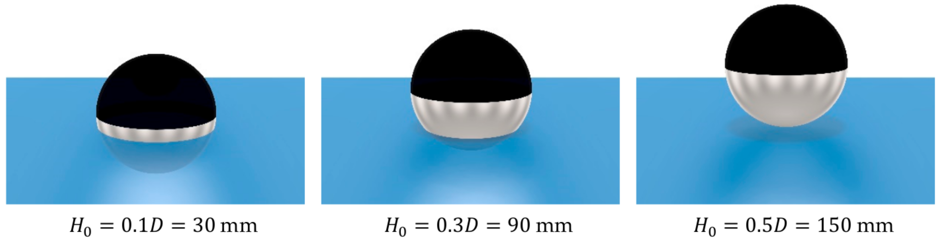
2.1. Test Case
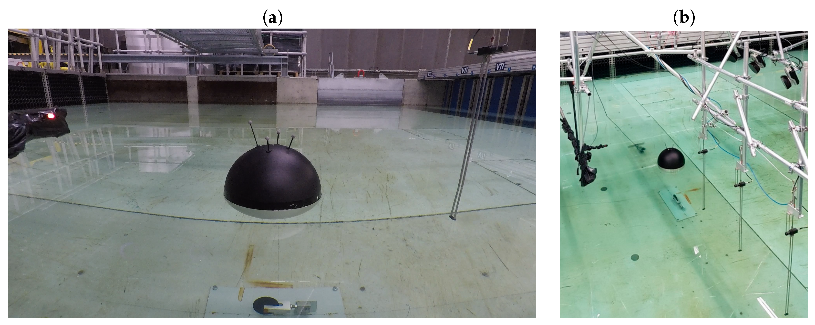
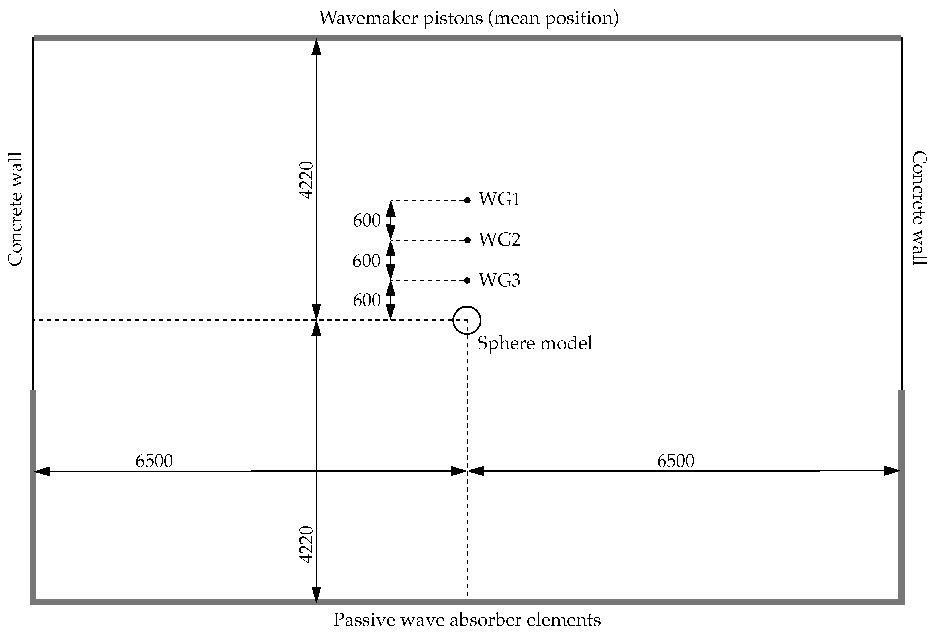
2.2. Description of Physical Experiments
2.2.1. Properties of the Sphere and the PWT
2.2.2. Measurement Equipment
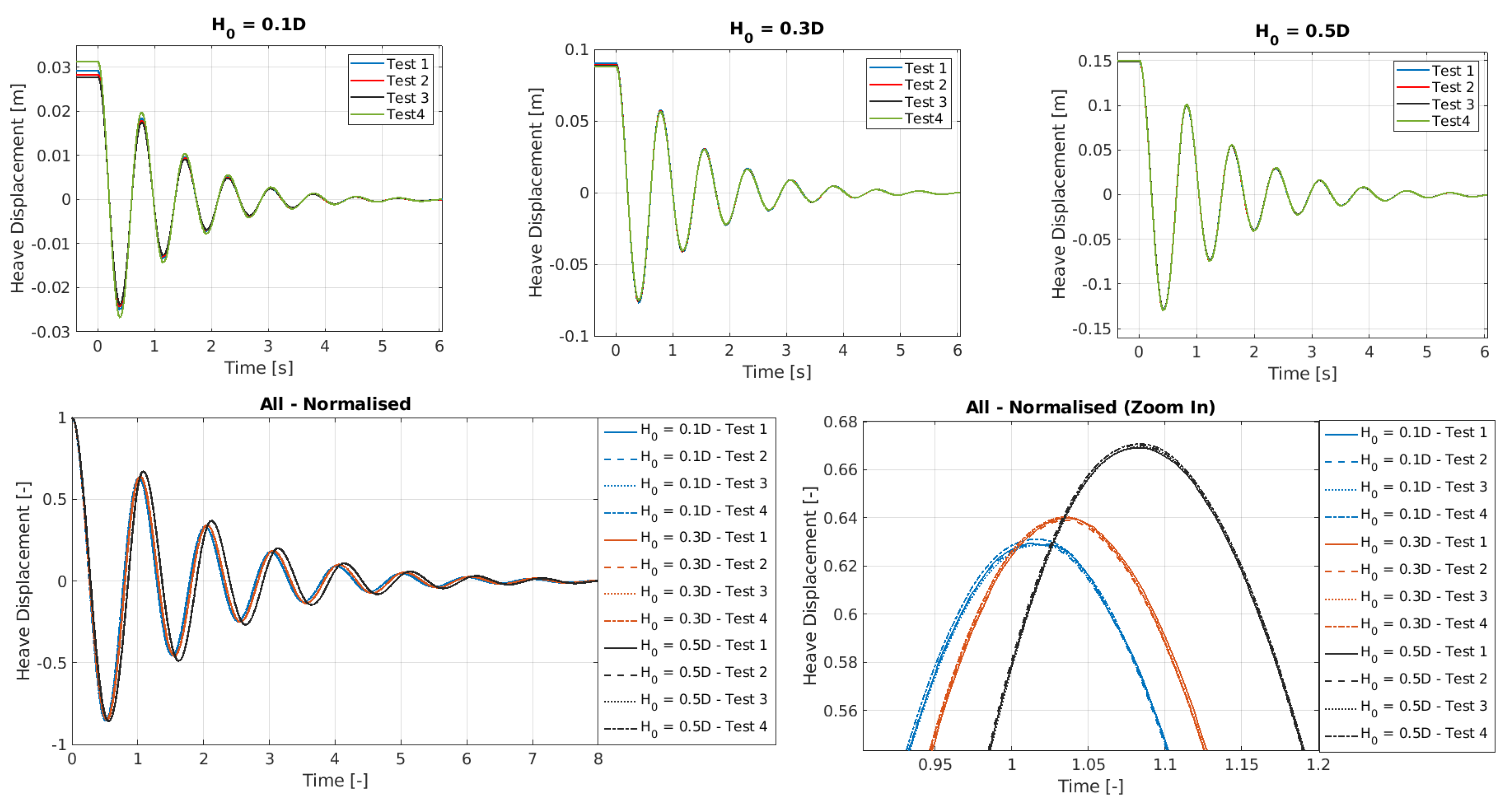
2.2.3. Heave Motion Results
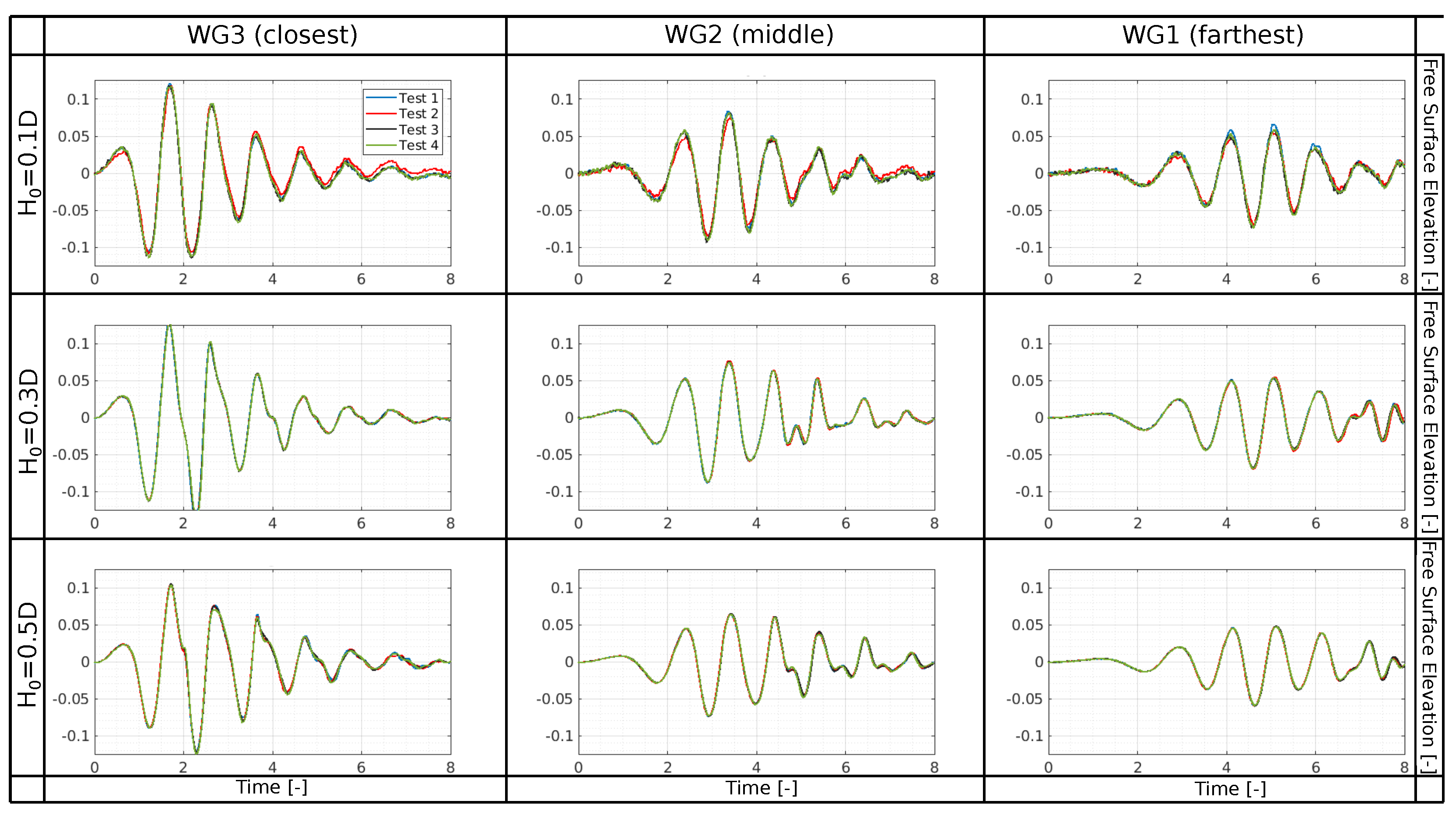
2.2.4. Wave Radiation Results
2.3. Description of the Axisymmetric Numerical Wave Tank
2.3.1. Implementation
2.3.2. Differences to the RANS5 Model
- Objective: The primary objective of the present A-NWT is to accurately capture both the heave motion of the sphere and the radiated wave field. In contrast, the RANS5 model focused solely on the sphere’s heave motion. This difference necessitates a more refined meshing strategy for the present A-NWT, especially around the free surface, and adjustments to various solver parameters to accommodate the additional complexity of wave radiation.
- OpenFoam version: The RANS5 model was implemented using the OpenFOAM v7 (Foundation) version of OpenFOAM, whereas the present study usesd the OpenFOAM v2312 (ESI) version.
- Sphere Motion Solver: The RANS5 model employs OpenFOAM’s sixDoFRigidBodyMotion solver, whereas for the present study the A-NWT uses OpenFOAM’s rigidBodyMotion solver.
- Water Depth and Tank Configuration: In the RANS5 model, the water depth was set to 6D to mitigate issues related to mesh deformation and the stability of the heaving sphere simulations. The deeper tank was chosen to avoid mesh compression problems beneath the sphere during large vertical displacements, which could lead to simulation crashes due to poor mesh quality. However, this increased depth was a compromise that potentially neglected the hydrodynamic effects of the tank floor on the sphere’s motion and the radiated wave field. In the current study, the A-NWT has been configured to use a water depth of 3D, matching the physical experiments. Extensive debugging and optimization were performed to stabilize the simulations with this more realistic tank depth, ensuring that the tank floor’s influence on wave radiation was accurately captured.
- Mesh Generation: The RANS5 model used a combination of OpenFOAM mesh generation tools of blockMesh and snappyHexMesh. However, this approach encountered issues in the present study when using the wedge boundary condition. Specifically, the mesh points generated around the sphere did not lie perfectly in a plane, causing conflicts with the axisymmetry requirements of the wedge boundary condition. To address this, the mesh generation was switched to cfMesh, which could ensure that the front face of the mesh maintained perfect alignment with the axisymmetric plane—a critical requirement for the wedge boundary condition and overall simulation accuracy.
3. Results
3.1. Sphere Motion
3.1.1. Temporal and Spatial Discretisation
- Time Step Two methodologies were evaluated for temporal discretisation:
- Adaptive Time Step Method: Enforcing the CFL condition, based on a maximum Courant number, C, and criterion with refinement levels of .
- Fixed Time Step Method: Using fixed time steps of .
- Mesh Setup
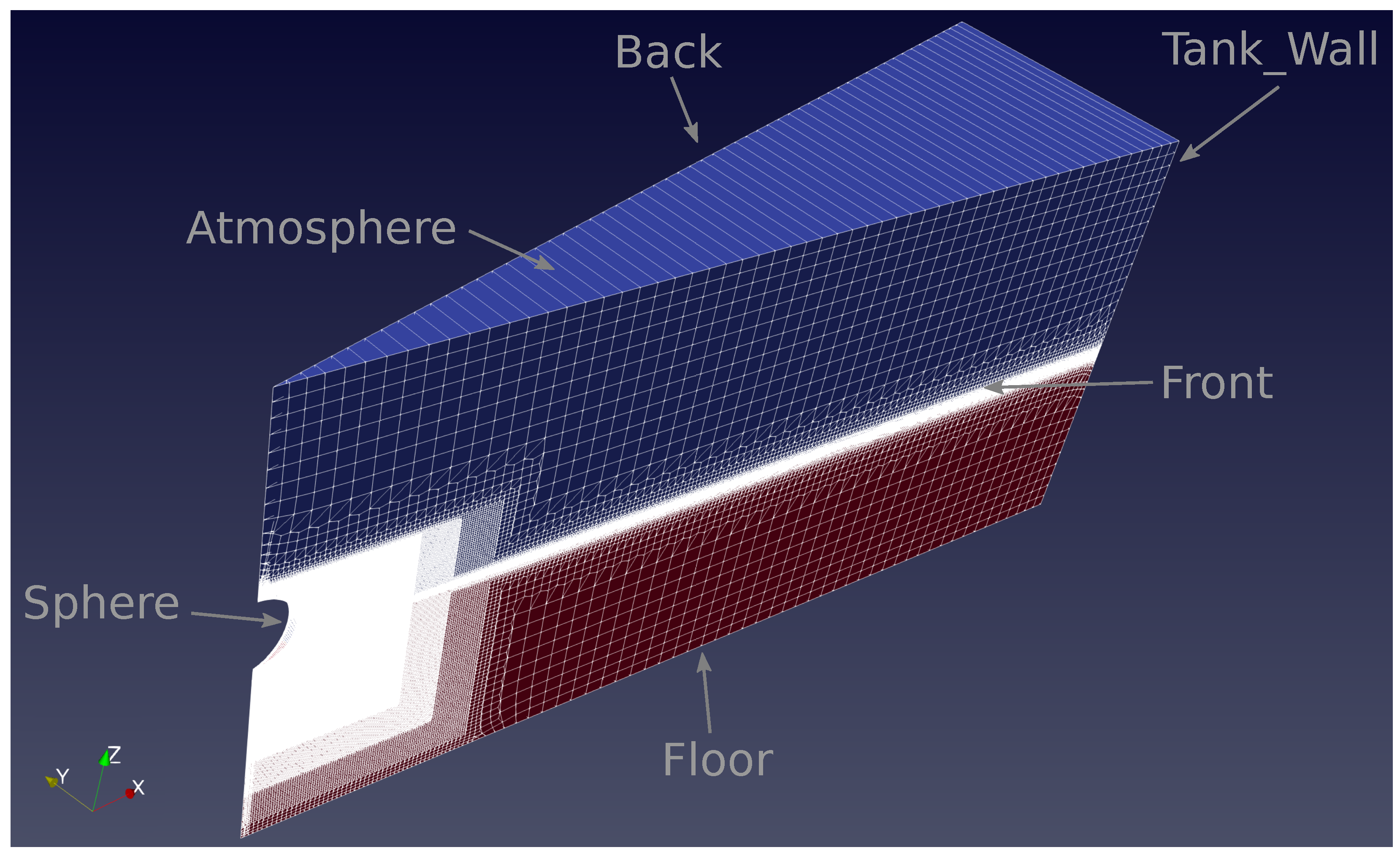
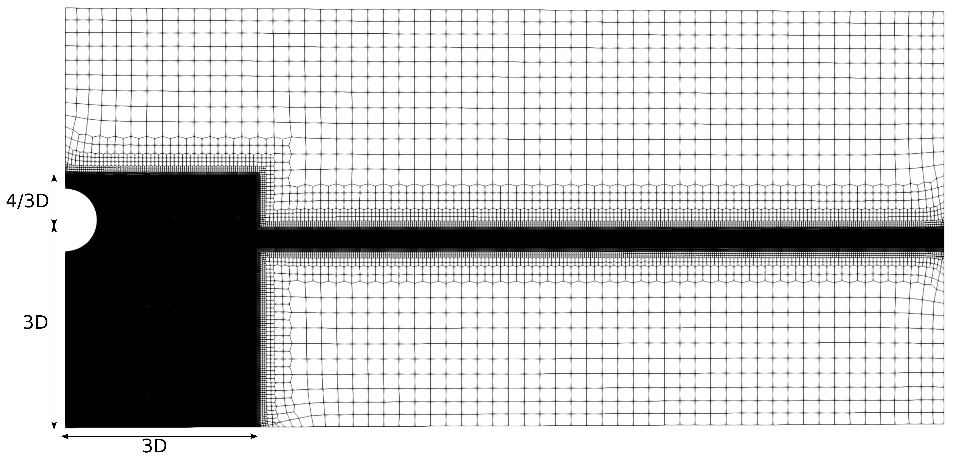
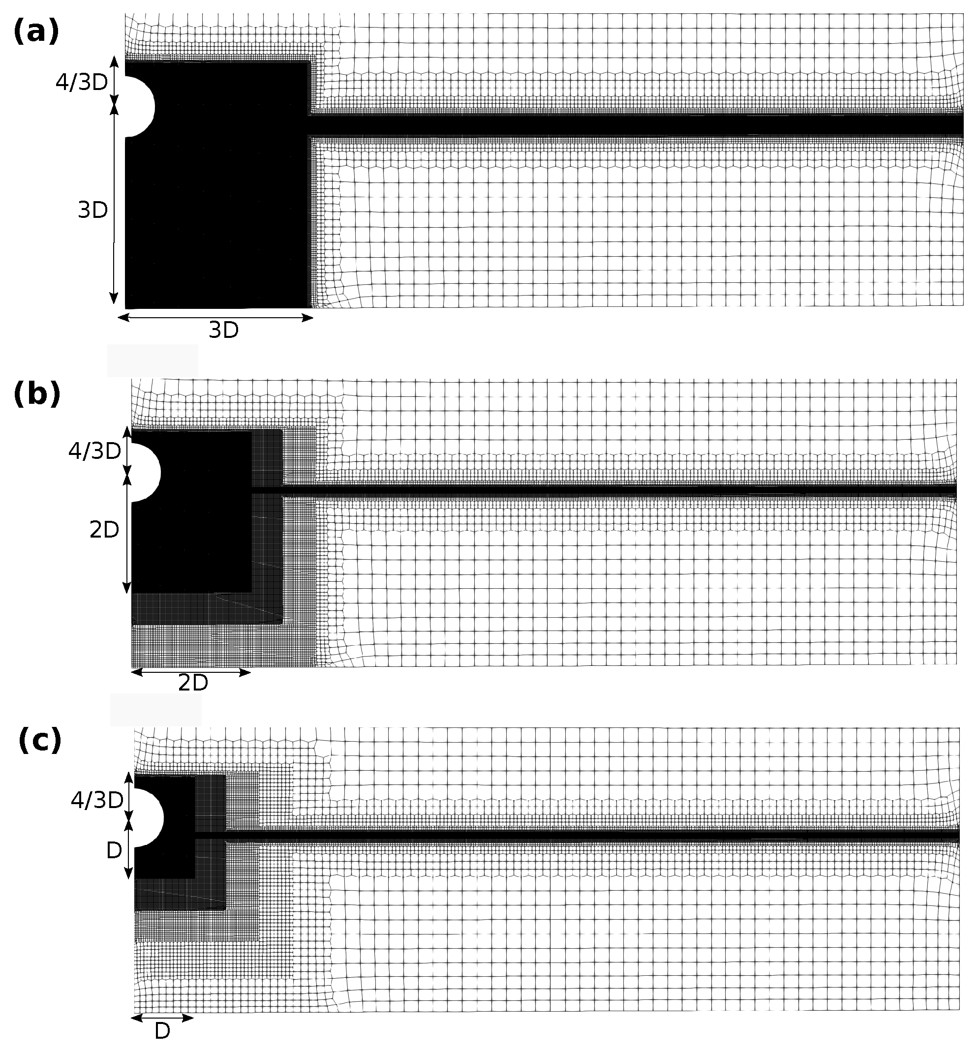
- The mesh setup is depicted in Figure 7. The tank wall is positioned 4.22 m from the sphere axis, the tank floor is set below the sphere center, and the atmosphere boundary is placed above the sphere’s center. The front and back faces have aspect ratios close to one, i.e., square and extruded around the central axis to form the wedge. The background mesh has a maximum cell size of D/4, with refinement levels bisecting in both directions of the x–z plane. The refinement region around the sphere center extends 3D horizontally and vertically below the sphere, and only 4/3D above the sphere center, as the influence of air is negligible [18]. The majority of cells are hexahedral and polyhedral cells are employed to connect different refinement levels.
- Mesh Resolutions
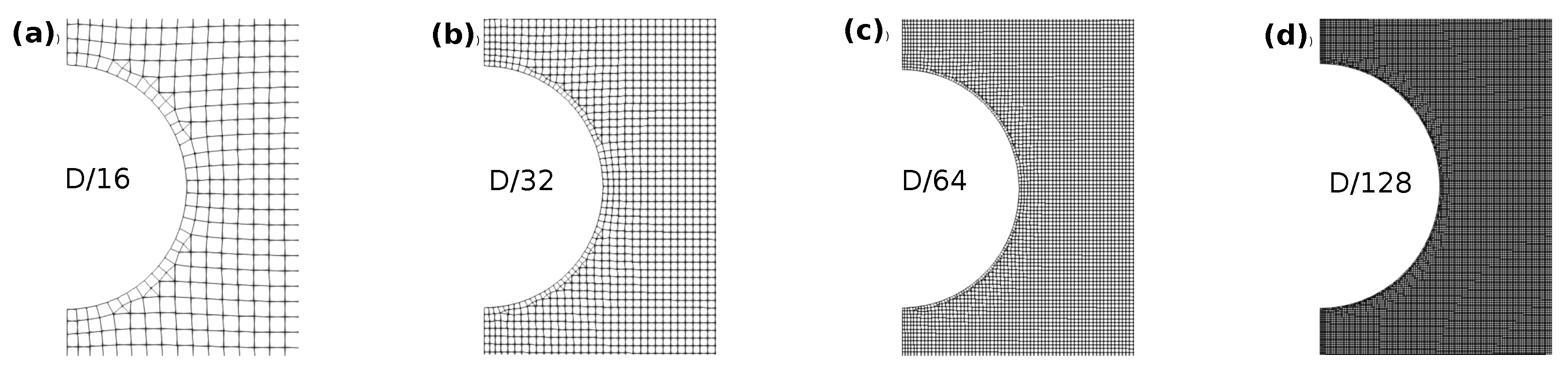
- Four levels of mesh refinement around the sphere and free surface are examined, , as depicted in Figure 8.
- Results of Parametric Study
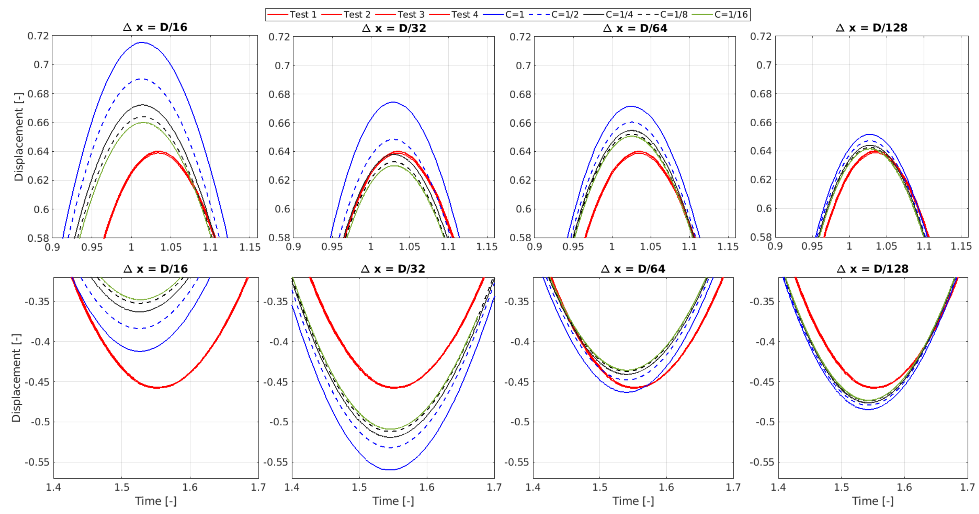
- Figure 9 compares the A-NWT results from the coarsest and finest discretizations (both spatial and temporal), for the adaptive and fixed time step methods, against the experimental data. As expected, with increased discretization resolution, the A-NWT results converge, and deviations to the experimental data were significantly reduced.
- Temporal Discretization: The amplitude of the A-NWT results decrease with finer temporal discretisation, converging to a solution for time steps of approximately and .
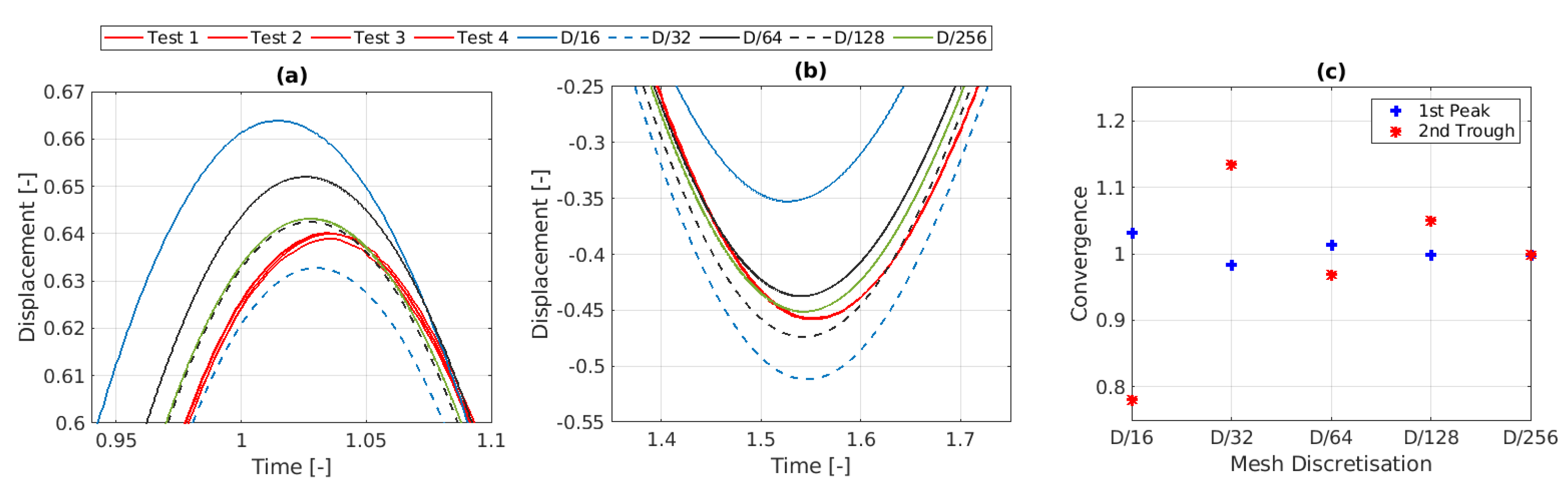
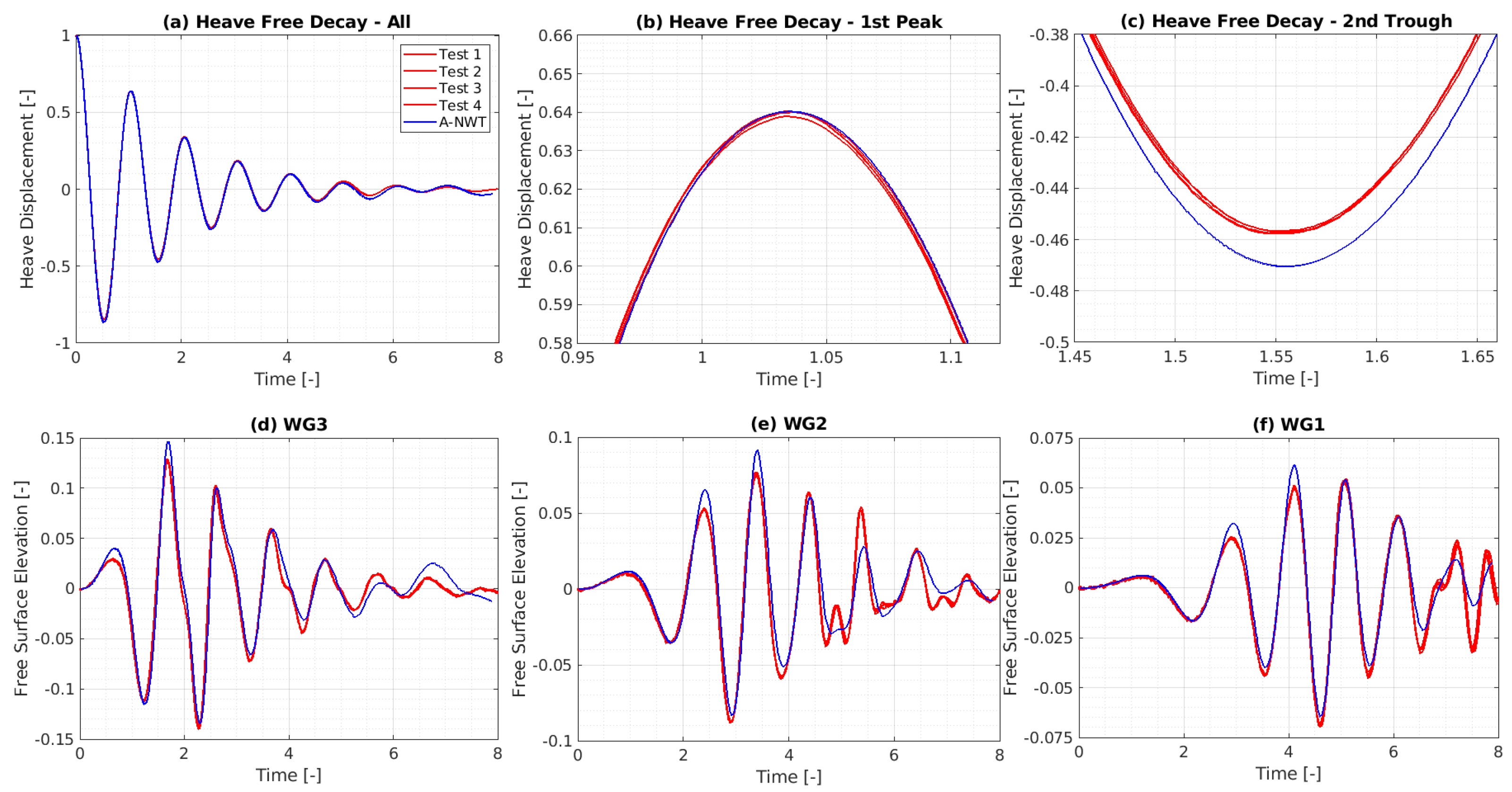
- Spatial Discretization: The A-NWT results are seen to converge as the mesh cell size is decreased; however, the convergence appears oscillatory. The oscillatory convergence is further illustrated in Figure 12, where results for all spatial discretisations (including an additional refinement level of ) are plotted for the same temporal discretisation (). The amplitude of the first peak for the mesh is within 0.15% of the amplitude for the mesh. For the second trough however, the difference is significantly larger, with the amplitude being 5.1% larger for the mesh compared to the mesh.
- Accuracy: The results appear to converge very closely to the experimental results. Both the amplitude and phase of the first peak and second trough appear to converge within 1% of the experimental results. Refinements to the solver settings, later in this Section, will look to further improve this accuracy.
- Selected Discretisation
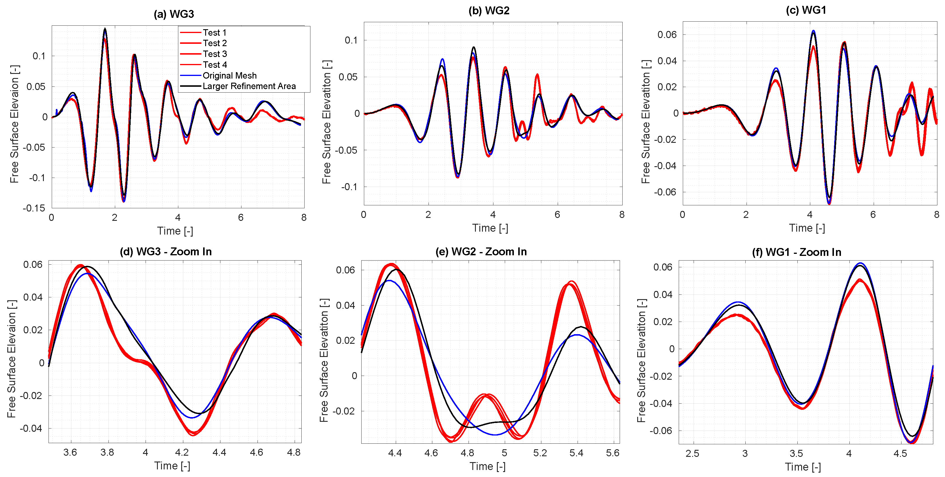
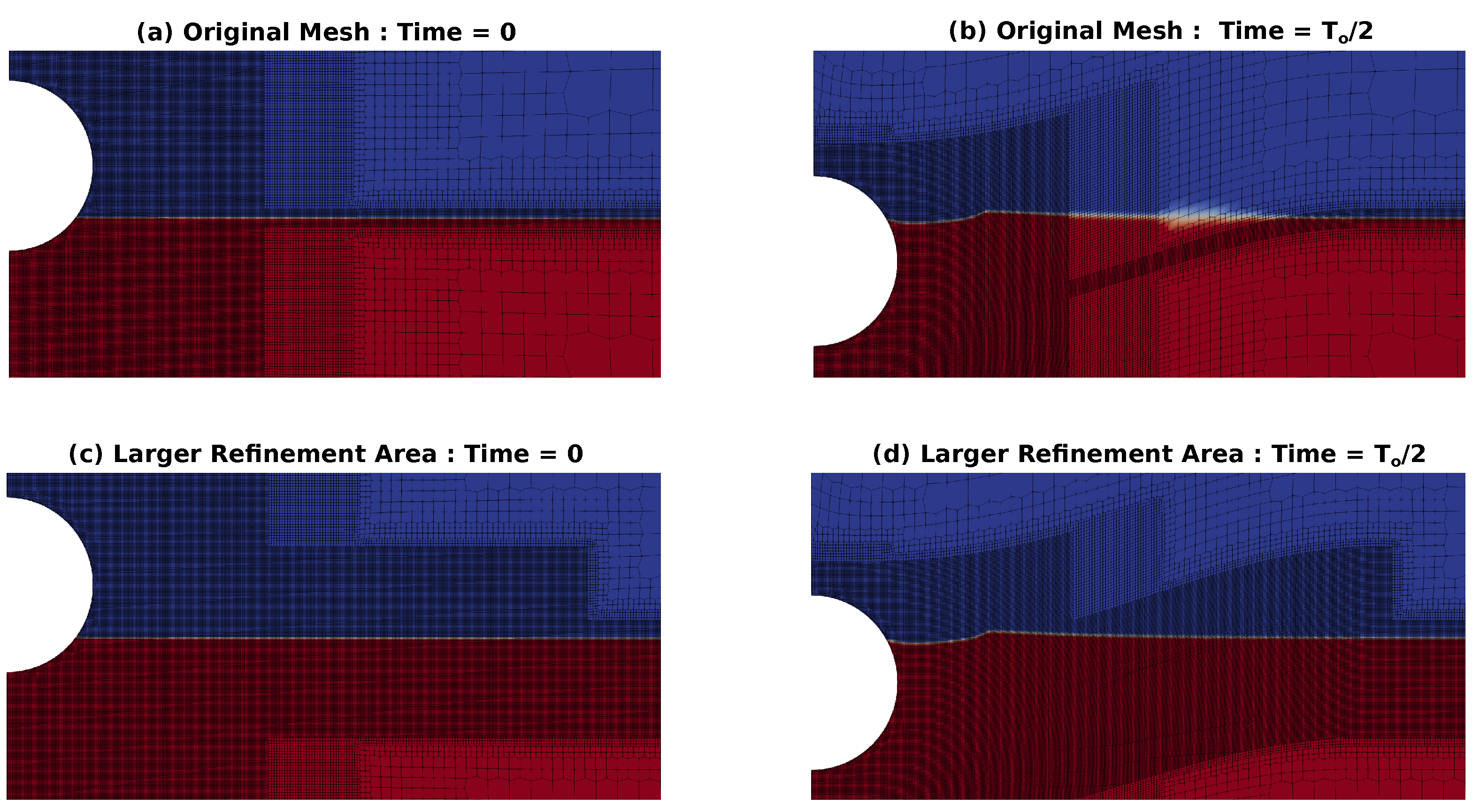
3.1.2. Mesh Refinement Area
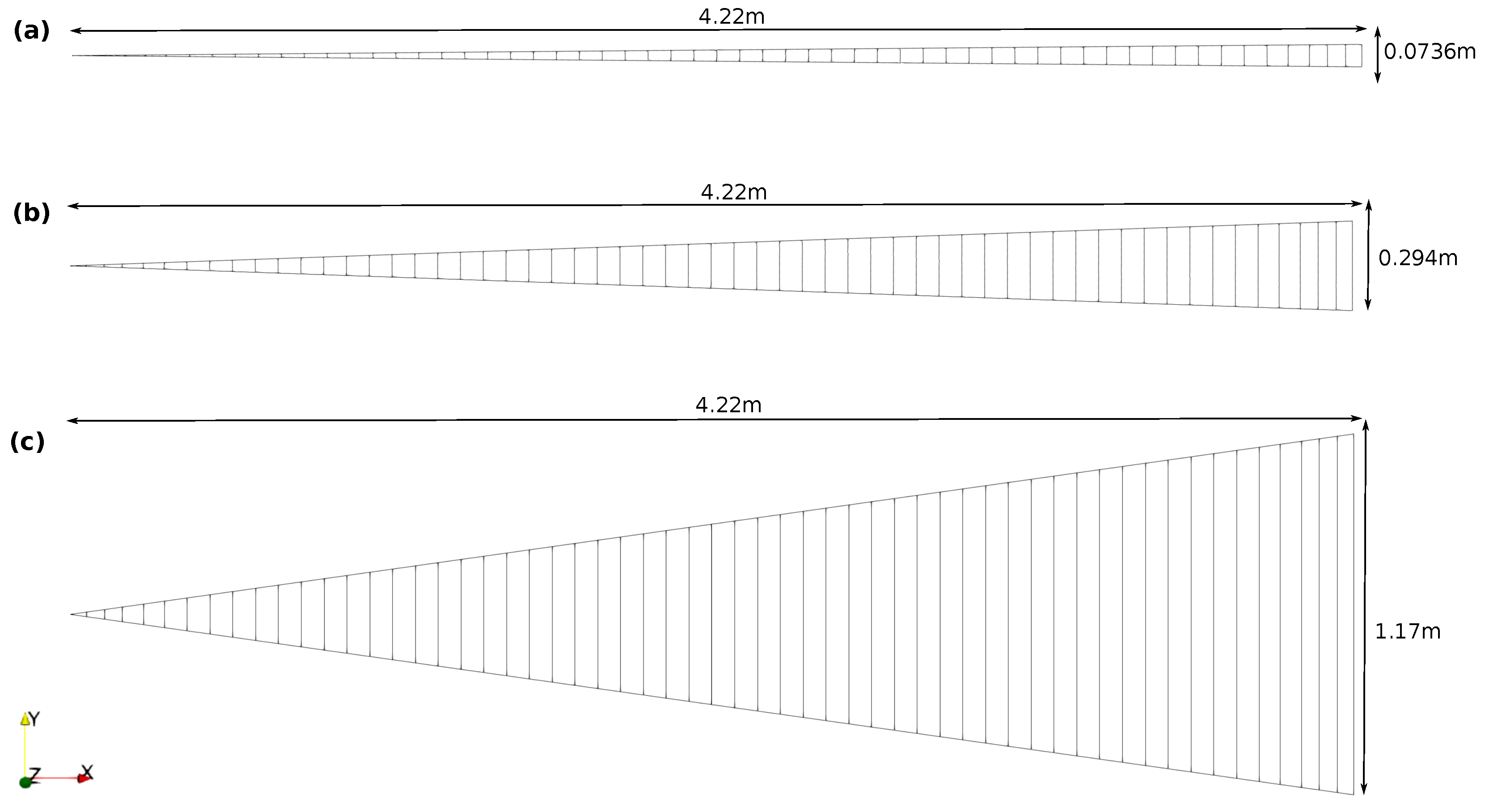
3.1.3. Wedge Angle
3.1.4. Solver Settings
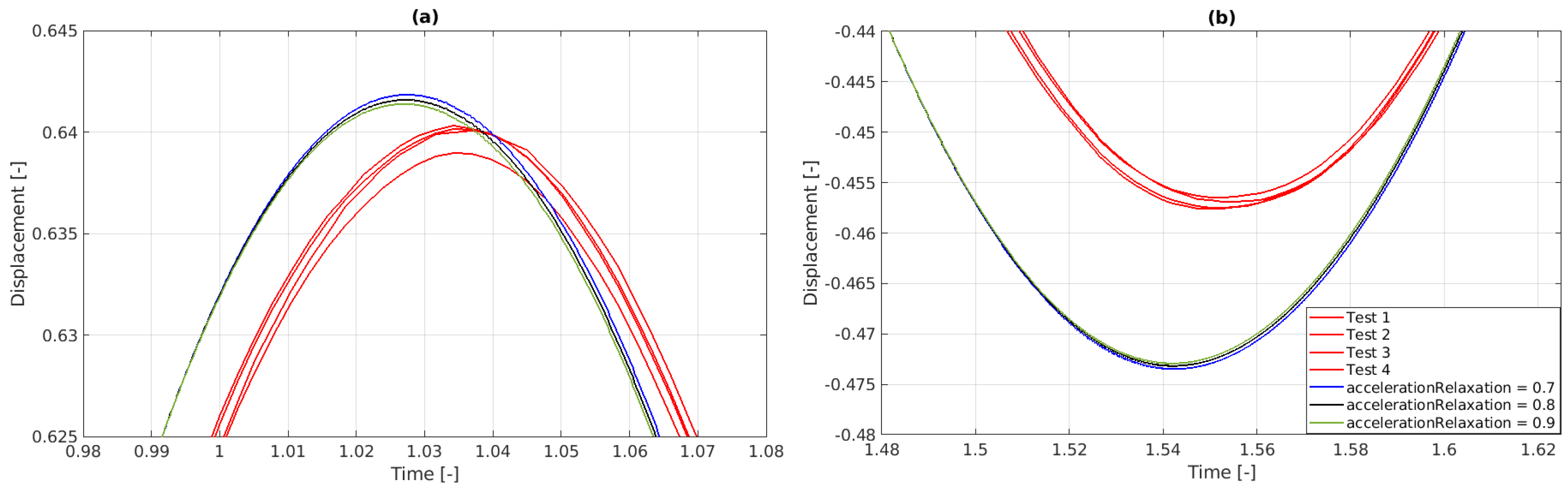
- Acceleration Relaxation
- The accelerationRelaxation parameter in the rigidBodyMotion solver helps stabilize simulations involving rigid body dynamics by smoothing out rapid changes in acceleration. This prevents numerical instabilities, such as oscillations or divergence, especially in cases with rapidly changing forces. While lowering this parameter increases stability, it may also slow down the body’s response to forces, potentially reducing accuracy. Therefore, it is essential to find a balance that ensures both stability and accurate motion representation. The value of accelerationRelaxation typically ranges between 0 and 1. A value of 1 means no relaxation is applied (i.e., the full computed acceleration is used), while a value closer to 0 means more relaxation is applied (i.e., the acceleration is smoothed more aggressively). The initial simulations employed an accelerationRelaxation of 0.7, which is compared in Figure 19 against results using accelerationRelaxation values of 0.8 and 0.9. Increasing the accelerationRelaxation is seen to not have a significant effect on the sphere motion, only very slightly decreasing the amplitude.
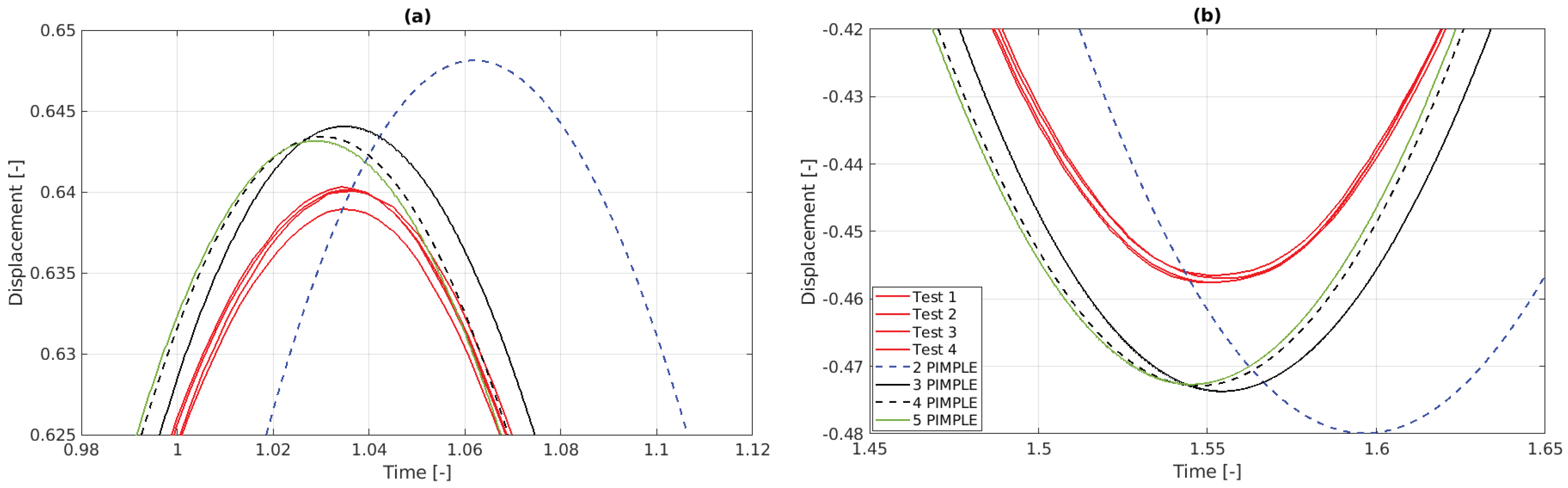
- PIMPLE Iterations
- The PIMPLE algorithm combines the PISO (Pressure-Implicit with Splitting of Operators) and SIMPLE (Semi-Implicit Method for Pressure-Linked Equations) methods to solve fluid flow equations, particularly in transient simulations. It iteratively corrects pressure and velocity fields within each time step, enhancing convergence and accuracy, especially in complex or large time step scenarios. While increasing PIMPLE iterations improves simulation accuracy by reducing numerical errors, it also increases computational time, requiring a balance between accuracy and efficiency. The initial simulations employed two PIMPLE iterations. Figure 20 compares the results using up five PIMPLE iterations, with dramatic improvement between one and two PIMPLE iterations, then another significant improvement between two and three PIMPLE iterations, after which the results start to converge.
- PIMPLE Iterations and Inner Loop Mesh Motion
- This approach involves updating the mesh geometry within each PIMPLE iteration. By continuously adjusting the mesh, the solver maintains alignment with the object’s motion, ensuring precise representation of wave patterns and force distributions. Although this process increases computational overhead, it enhances simulation fidelity and prevents inaccuracies that could arise from mesh distortion or misalignment. The initial simulations did not update the mesh motion within each PIMPLE iteration. Figure 21 shows the results when the inner loop mesh motion was applied. Here, both the amplitude and the period of the sphere motion are seen to decrease with the increasing number of PIMPLE iterations. Compared to the results in Figure 20, it can be seen that employing inner loop mesh motion results in the sphere motion being closer to the experimental results.
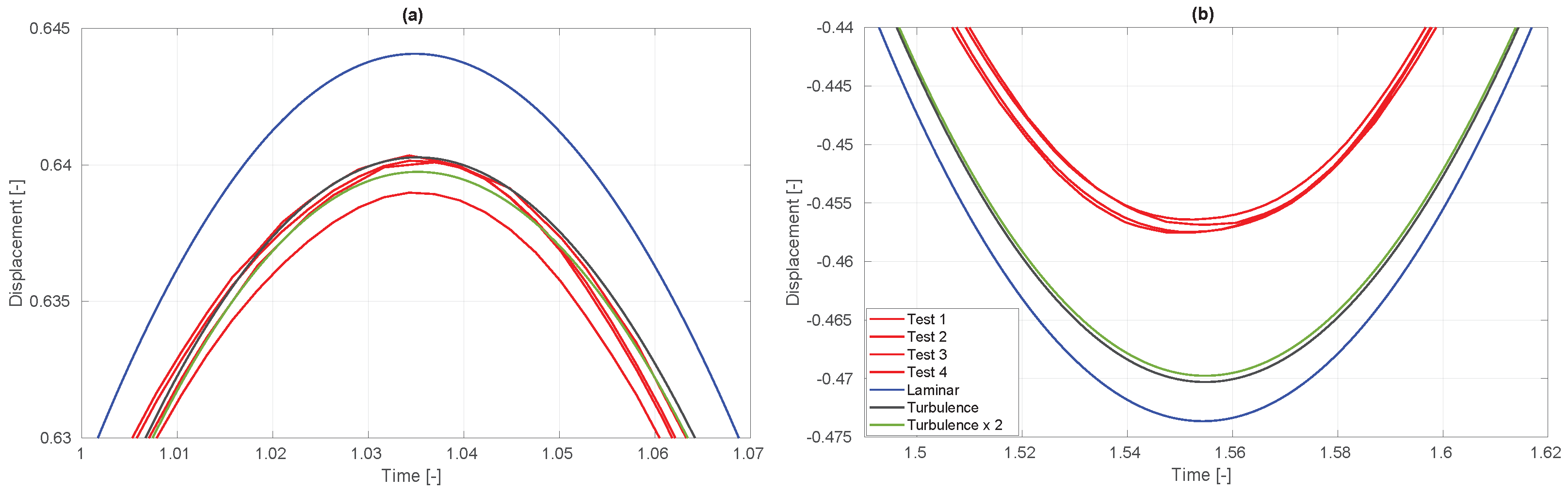
- Turbulence Modeling
- Turbulence modeling uses mathematical models like the SST [47] to simulate turbulent effects without resolving small-scale motions directly, which would require very fine meshes and significant computational power. These models aim at enhancing simulation accuracy, particularly near walls and in wake regions, but at the cost of decreased computational efficiency. Initial simulations assumed laminar flow, with no turbulence models applied. Figure 22 shows the impact of adding the SST model using both default (Default refers to the parameter values used in the interFoam tutorial cases—DTCHull, DTCHullMoving, and motorBike included in the OpenFOAM version 2306 release—that employ the SST model.) tutorials and doubled parameter values. Including this turbulence model reduced the amplitude of the sphere motion closer to the experiments, with the trace at the first peak falling within the spread of the four experimental repetitions (Test 1–4). The amplitude of the trough still overshoots the experimental results, however the inclusion of the turbulence model reduces this overshoot from 3.3% to 2.7%. Doubling the turbulence parameters slightly lowered the amplitude further, indicating some sensitivity to these values.
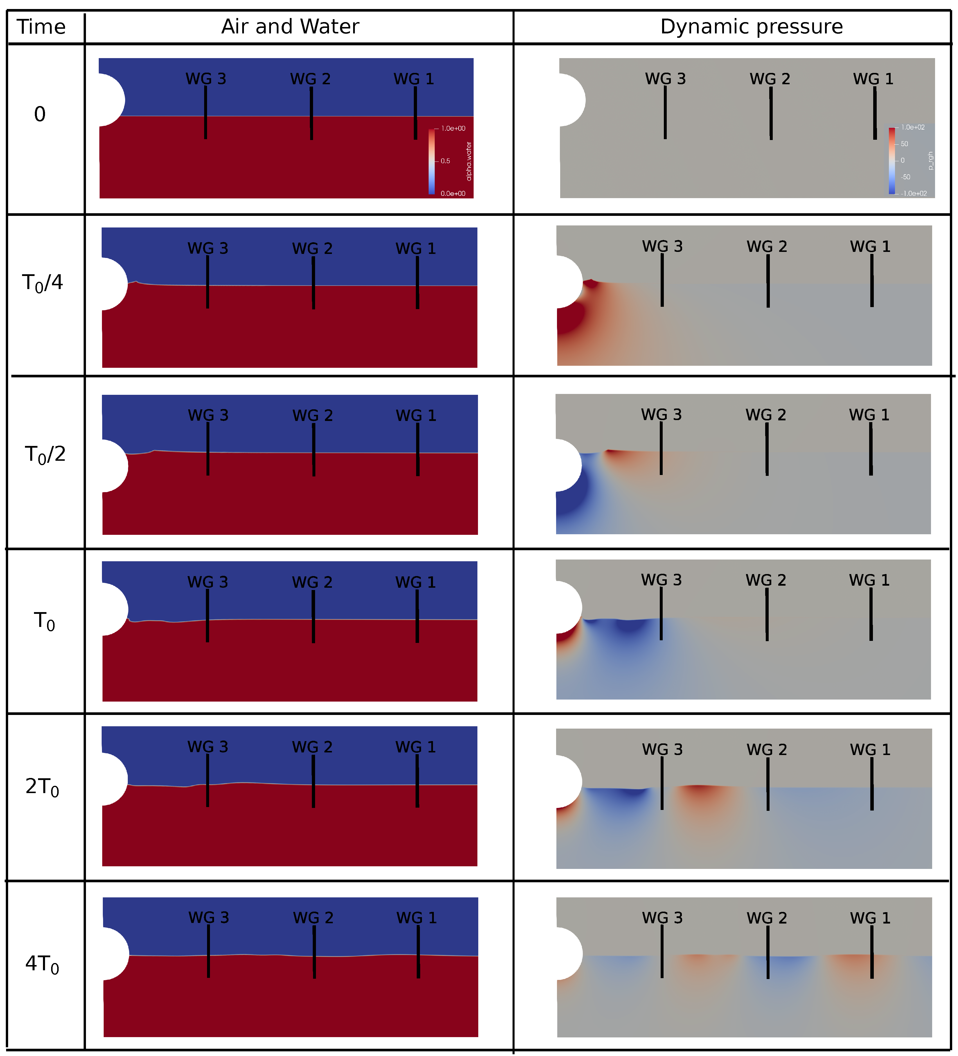
3.2. Radiated Wave
3.3. The A-NWT Results
3.4. Validation Against Other Drop Heights
4. Discussion
4.1. The A-NWT Performance
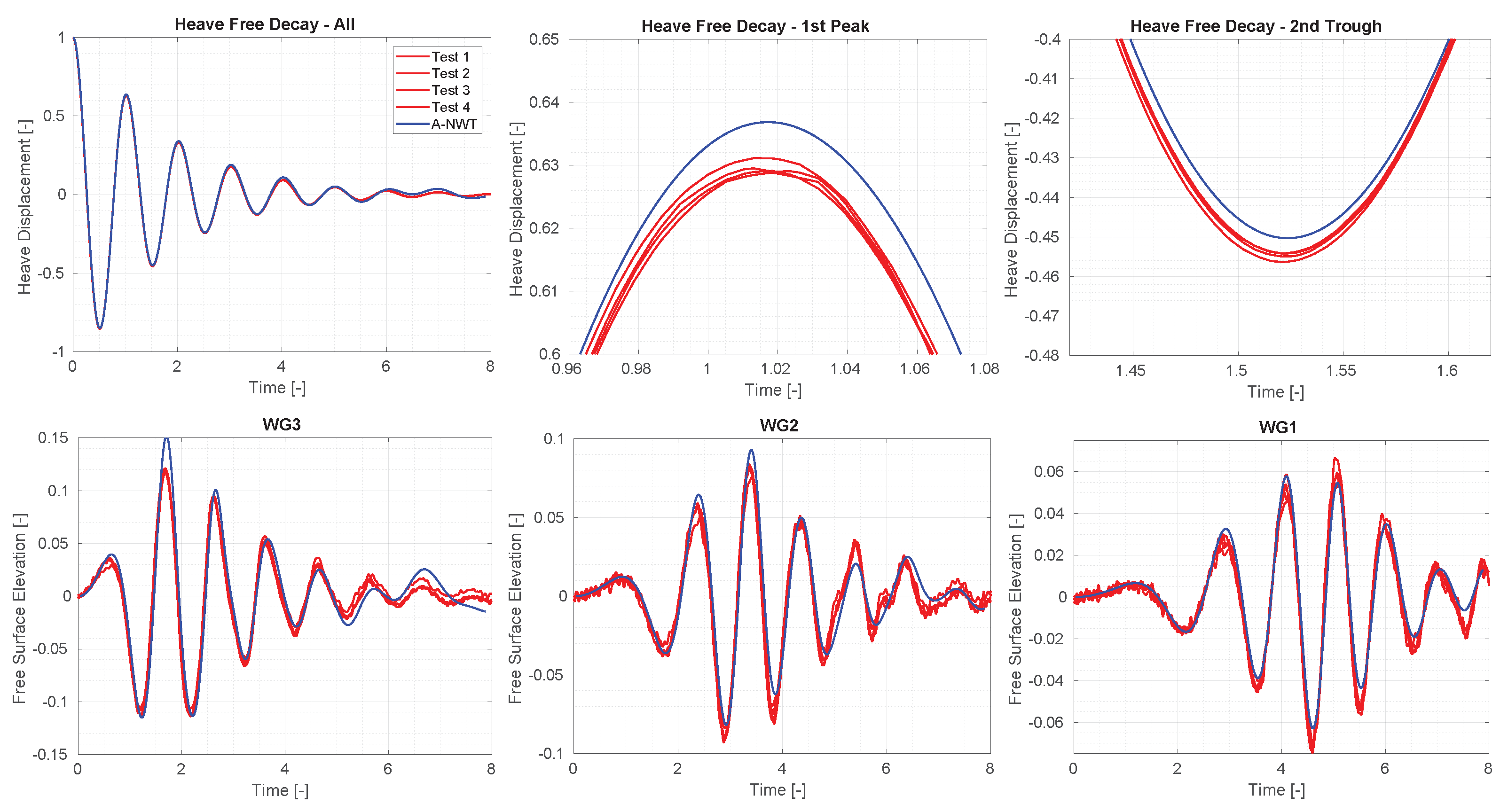
- Accuracy: The A-NWT results demonstrated excellent accuracy across multiple initial drop heights. For the heave motion, the alignment between A-NWT results and experimental data improved with increasing initial drop height. The A-NWT results for the largest drop height () fell within the range of the four repeated tests in the PWT, showcasing exceptional accuracy. For the middle drop height (), the peaks matched the experimental results well, though the troughs were slightly overpredicted. The smallest drop height () exhibited minor discrepancies for both peaks and troughs. Regarding wave radiation, the A-NWT successfully captured the dominant trend of the free surface elevation at the three different wave gauge locations. However, a second harmonic component, evident in the experimental results, was not as pronounced in the A-NWT simulations. Additionally, discrepancies increased towards the end of the signals, likely due to the breakdown of axisymmetry in the PWT as the earliest radiated waves reflected off the tank walls and returned to the wave gauges.
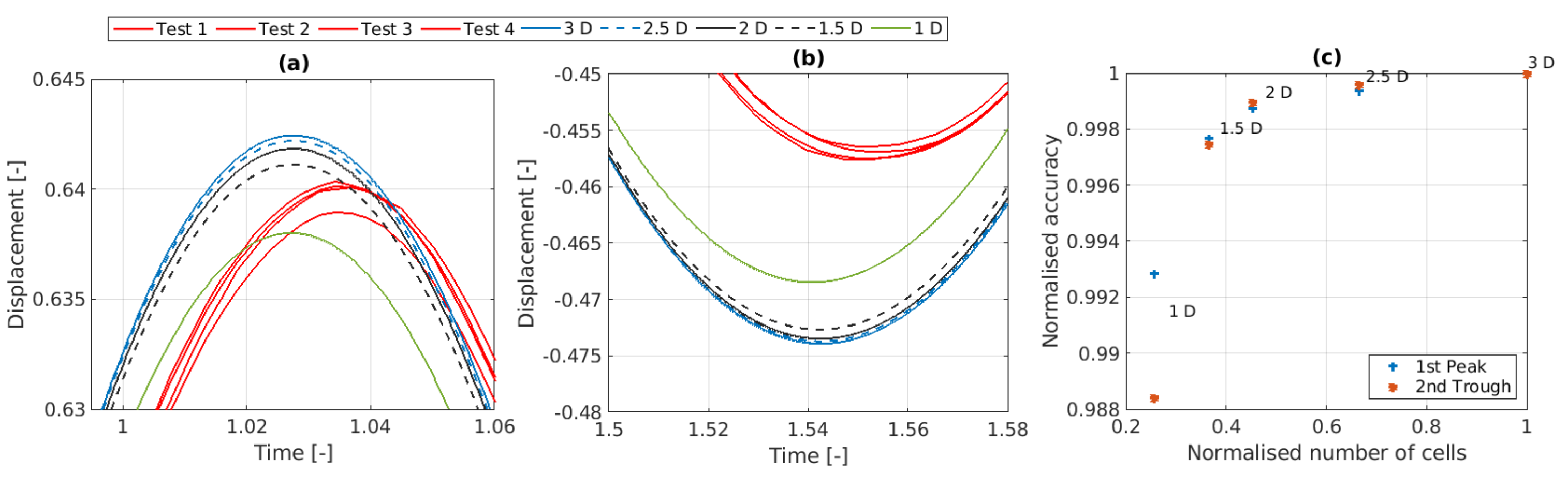
- Computational Expense: The A-NWT’s computational efficiency is a significant advantage. The final A-NWT mesh comprised approximately 150,000 cells, and simulation runtimes were manageable even on modest computational resources. Running the A-NWT simulations on 24 cores required 10.7 [h], on 12 cores 16.7 [h] and on six cores 25.8 [h]. To estimate the computational expense when moving to a three-dimensional simulation, the plot in Figure 18c offers some insight from the observation that the results appear to begin diverging between 2–4° (It should be noted that the mesh cells comprise straight lines only. Capturing the curvature of the radial faces with a spline instead may alter this result). Angularly discretising 360° by such sized wedges requires between 90–180 cells in the third dimension, thus the total cell count for the three dimensional NWT could be around 15 M. To run a simulation within a day, would require a HPC with more than 600 cores (Running the simulation on six cores took approximately 24 [h], with 25 k cells per core. Therefore, parallelising the 15 M cells to 25 k cells per core would require 600 cores.
4.2. Initial Time Steps
4.3. Future Studies
- Mesh Optimization—Further studies can work to reduce the required number of mesh cells whilst retaining the accuracy of the results. Increasing the aspect ratio of cells in certain regions, to increase/decrease the spatial discretization resolution more in one direction without also increasing in the other direction, might be of interest.
- Time Step Refinement—While the chosen time step of was found to be effective, it was selected based on a trial with a discretization level of 2. Future work could explore intermediate values between and , potentially identifying an optimal balance that allows for even larger time steps without compromising accuracy.
- Overset Mesh—Compare performance of the current mesh morphing with the overset method. While the mesh morphing is seen to work well in heave, for other degrees of freedom, in particular pitch, roll and yaw, the mesh morphing gets twisted and simulations crash [46]. For these cases, the overset approach is necessary within OpenFOAM, therefore it would be of interest to understand how well it performs, in terms of accuracy and simulation time, compared to the mesh morphing method.
- Wave Radiation—Further investigation to improve the simulation of the wave radiation, in order to replicate the smaller initial peak values and and the emergence of a second harmonic observed in experimental data. Future studies could benefit from analyzing wave radiation in the frequency domain, allowing for a more detailed comparison and understanding of these phenomena.
5. Conclusions
Author Contributions
Funding
Data Availability Statement
Conflicts of Interest
Abbreviations
| A-NWT | Axisymmetric Numerical Wave Tank |
| CFD | Computational Fluid Dynamics |
| D | Diameter of Sphere |
| NWT | Numerical Wave Tank |
| PWT | Physical Wave Tank |
| RANS | Reynolds Averaged Navier Stokes |
| WEC | Wave Energy Converter |
References
- Ortloff, C.; Krafft, M. Numerical Test Tank: Simulation of Ocean Engineering Problems by Computational Fluid Dynamics. In Proceedings of the Offshore Technology Conference, OTC 1997, Houston, TX, USA, 5–8 May 1997. pp. OTC–8269. [Google Scholar]
- Kim, C.; Clement, A.; Tanizawa, K. Recent research and development of numerical wave tanks—A review. Int. J. Offshore Polar Eng. 1999, 9, ISOPE-99-09-4-241. [Google Scholar]
- Stern, F.; Wang, Z.; Yang, J.; Sadat-Hosseini, H.; Mousaviraad, M.; Bhushan, S.; Diez, M.; Sung-Hwan, Y.; Wu, P.C.; Yeon, S.M.; et al. Recent progress in CFD for naval architecture and ocean engineering. J. Hydrodyn. 2015, 27, 1–23. [Google Scholar] [CrossRef]
- Windt, C.; Davidson, J.; Ringwood, J.V. High-fidelity numerical modelling of ocean wave energy systems: A review of computational fluid dynamics-based numerical wave tanks. Renew. Sustain. Energy Rev. 2018, 93, 610–630. [Google Scholar] [CrossRef]
- Xu, S.; Xue, Y.; Zhao, W.; Wan, D. A review of high-fidelity computational fluid dynamics for floating offshore wind turbines. J. Mar. Sci. Eng. 2022, 10, 1357. [Google Scholar] [CrossRef]
- Zhang, W.; Calderon-Sanchez, J.; Duque, D.; Souto-Iglesias, A. Computational Fluid Dynamics (CFD) applications in Floating Offshore Wind Turbine (FOWT) dynamics: A review. Appl. Ocean. Res. 2024, 150, 104075. [Google Scholar] [CrossRef]
- Collins, K.; Iglesias, G.; Greaves, D.; Toffoli, A.; Stripling, S. The New Coast Laboratory at Plymouth University: A World-Class Facility for Marine Energy. In From Sea to Shore–Meeting the Challenges of the Sea: (Coasts, Marine Structures and Breakwaters 2013); ICE Publishing: London, UK, 2014; pp. 1326–1335. [Google Scholar]
- Draycott, S.; Davey, T.; Ingram, D.; Day, A.; Johanning, L. The SPAIR method: Isolating incident and reflected directional wave spectra in multidirectional wave basins. Coast. Eng. 2016, 114, 265–283. [Google Scholar] [CrossRef]
- Klinghammer, C.; Tonda, P.L.; Caubilla, P.H. Design Optimization for a Passive Mesh Screen Wave Absorber for the CCOB. Coast. Eng. Proc. 2012, volume, 36. [Google Scholar] [CrossRef]
- Carneiro, M.L.; de Mello, P.C.; Labate, F.; Araujo, A.A.; Simos, A.N.; Tannuri, E.A. USP Wave Basin: Active wave absorption and generation algorithms. Mar. Syst. Ocean. Technol. 2010, 5, 67–73. [Google Scholar] [CrossRef]
- Windt, C.; Davidson, J.; Schmitt, P.; Ringwood, J.V. On the assessment of numerical wave makers in CFD simulations. J. Mar. Sci. Eng. 2019, 7, 47. [Google Scholar] [CrossRef]
- van Essen, S.; Scharnke, J.; Bunnik, T.; Düz, B.; Bandringa, H.; Hallmann, R.; Helder, J. Linking experimental and numerical wave modelling. J. Mar. Sci. Eng. 2020, 8, 198. [Google Scholar] [CrossRef]
- Schmitt, P.; Doherty, K.; Clabby, D.; Whittaker, T. The opportunities and limitations of using CFD in the development of wave energy converters. In Proceedings of the Royal Institution of Naval Architects Marine & Offshore Renewable Energy Conference, London, UK, 26 September 2012; pp. 89–97. [Google Scholar]
- Kim, J.W.; Jang, H.; Baquet, A.; O’Sullivan, J.; Lee, S.; Kim, B.; Read, A.; Jasak, H. Technical and economic readiness review of CFD-based numerical wave basin for offshore floater design. In Proceedings of the Offshore Technology Conference, OTC 2016, Houston, TX, USA, 2–5 May 2016; p. D011S014R002. [Google Scholar]
- Ferziger, J.H.; Perić, M.; Street, R.L. Computational Methods for Fluid Dynamics; Springer: Berlin/Heidelberg, Germany, 2019. [Google Scholar]
- Miquel, A.M.; Kamath, A.; Alagan Chella, M.; Archetti, R.; Bihs, H. Analysis of different methods for wave generation and absorption in a CFD-based numerical wave tank. J. Mar. Sci. Eng. 2018, 6, 73. [Google Scholar] [CrossRef]
- Machado, F.M.M.; Lopes, A.M.G.; Ferreira, A.D. Numerical simulation of regular waves: Optimization of a numerical wave tank. Ocean. Eng. 2018, 170, 89–99. [Google Scholar] [CrossRef]
- Larsen, B.E.; Fuhrman, D.R.; Roenby, J. Performance of interFoam on the simulation of progressive waves. Coast. Eng. J. 2019, 61, 380–400. [Google Scholar] [CrossRef]
- Li, Z.; Bouscasse, B.; Ducrozet, G.; Gentaz, L.; Le Touzé, D.; Ferrant, P. Spectral wave explicit navier-stokes equations for wave-structure interactions using two-phase computational fluid dynamics solvers. Ocean. Eng. 2021, 221, 108513. [Google Scholar] [CrossRef]
- Martin, M.B.; Harris, J.C.; Filipot, J.F.; Hulin, F.; Tassin, A.; Renaud, P. Deep water focused breaking wave loads on a fixed cylinder. Coast. Eng. 2023, 186, 104397. [Google Scholar] [CrossRef]
- Mavrakos, A.S.; Konispoliatis, D.N.; Ntouras, D.G.; Papadakis, G.P.; Mavrakos, S.A. Hydrodynamics of Moonpool-type Floaters: A theoretical and a CFD formulation. Energies 2022, 15, 570. [Google Scholar] [CrossRef]
- Sun, J.Y.; Sun, S.L.; Sun, S.Z.; Ren, H.L. The impact of piston and sloshing motions on added resistance from moonpool configurations. Ocean. Eng. 2023, 267, 113179. [Google Scholar] [CrossRef]
- Nguyen, H.Q.; Vu, N.K. Numerical Simulation of Ship Sailing In Regular Head Waves Using CFD Method. Int. J. Mech. Eng. Robot. Res. 2021, 10, 183–188. [Google Scholar] [CrossRef]
- Ntouras, D.; Papadakis, G.; Belibassakis, K. Ship bow wings with application to trim and resistance control in calm water and in waves. J. Mar. Sci. Eng. 2022, 10, 492. [Google Scholar] [CrossRef]
- Devolder, B.; Stratigaki, V.; Troch, P.; Rauwoens, P. CFD simulations of floating point absorber wave energy converter arrays subjected to regular waves. Energies 2018, 11, 641. [Google Scholar] [CrossRef]
- Bharath, A.; Nader, J.R.; Penesis, I.; Macfarlane, G. Nonlinear hydrodynamic effects on a generic spherical wave energy converter. Renew. Energy 2018, 118, 56–70. [Google Scholar] [CrossRef]
- Beyer, F.; Choisnet, T.; Kretschmer, M.; Cheng, P.W. Coupled MBS-CFD simulation of the IDEOL floating offshore wind turbine foundation compared to wave tank model test data. In Proceedings of the ISOPE International Ocean and Polar Engineering Conference, ISOPE 2015, Big Island, HI, USA, 21–26 June 2015. pp. ISOPE–I. [Google Scholar]
- Wang, Y.; Chen, H.C.; Koop, A.; Vaz, G. Verification and validation of CFD simulations for semi-submersible floating offshore wind turbine under pitch free-decay motion. Ocean. Eng. 2021, 242, 109993. [Google Scholar] [CrossRef]
- Di Paolo, B.; Lara, J.L.; Barajas, G.; Losada, Í.J. Wave and structure interaction using multi-domain couplings for Navier-Stokes solvers in OpenFOAM®. Part I: Implementation and validation. Coast. Eng. 2021, 164, 103799. [Google Scholar] [CrossRef]
- Di Paolo, B.; Lara, J.L.; Barajas, G.; Losada, I.J. Waves and structure interaction using multi-domain couplings for Navier-Stokes solvers in OpenFOAM®. Part II: Validation and application to complex cases. Coast. Eng. 2021, 164, 103818. [Google Scholar] [CrossRef]
- Kramer, M.B.; Andersen, J.; Thomas, S.; Bendixen, F.B.; Bingham, H.; Read, R.; Holk, N.; Ransley, E.; Brown, S.; Yu, Y.H.; et al. Highly accurate experimental heave decay tests with a floating sphere: A public benchmark dataset for model validation of fluid–structure interaction. Energies 2021, 14, 269. [Google Scholar] [CrossRef]
- Eskilsson, C.; Shiri, A.; Katsidoniotakis, E. Solution verification of WECs: Comparison of methods to estimate numerical uncertainties in the OES wave energy modelling task. In Proceedings of the 15th European Wave and Tidal Energy Conference, Bilbao, Spain, 3–7 September 2023. [Google Scholar]
- Palm, J.; Eskilsson, C. Verification and validation of MoodyMarine: A free simulation tool for modelling moored MRE devices. In Proceedings of the 15th European Wave and Tidal Energy Conference, Bilbao, Spain, 3–7 September 2023. [Google Scholar]
- Eskilsson, C.; Pashami, S.; Holst, A.; Palm, J. Hierarchical approaches to train recurrent neural networks for wave-body interaction problems. In Proceedings of the ISOPE International Ocean and Polar Engineering Conference, ISOPE 2023, Ottawa, ON, Canada, 19–23 June 2023. pp. ISOPE–I. [Google Scholar]
- Eskilsson, C.; Pashami, S.; Holst, A.; Palm, J. A hybrid linear potential flow-machine learning model for enhanced prediction of WEC performance. In Proceedings of the European Wave and Tidal Energy Conference 2023, Bilbao, Spain, 3–7 September 2023; Volume 15. [Google Scholar]
- Eskilsson, C.; Pashami, S.; Holst, A.; Palm, J. Estimation of nonlinear forces acting on floating bodies using machine learning. In Advances in the Analysis and Design of Marine Structures; CRC Press: Boca Raton, FL, USA, 2023; pp. 63–72. [Google Scholar]
- Zafeiris, S.; Papadakis, G. An Overset Algorithm for Multiphase Flows using 3D Multiblock Polyhedral Meshes. arXiv 2023, arXiv:2305.17074. [Google Scholar]
- Bengtsson, M.; Delvret, M. Motion Decay of a Floating Object. Master’s Thesis, Chalmers Universtiy of Technology, Göteborg, Sweden, 2021. [Google Scholar]
- Colling, J.K.; Jafari Kang, S.; Dehdashti, E.; Husain, S.; Masoud, H.; Parker, G.G. Free-decay heave motion of a spherical buoy. Fluids 2022, 7, 188. [Google Scholar] [CrossRef]
- Andersen, J. Hydrodynamic Modelling of Offshore Renewables: Experimental Benchmark Datasets and Numerical Simulation. Ph.D. Thesis, Aalborg Universitetsforlag, Aalborg, Denmark, 2023. [Google Scholar] [CrossRef]
- IEA. IEA OES Wave Energy Converters Modelling Verification and Validation. 2016. Available online: https://www.ocean-energy-systems.org/oes-projects/wave-energy-converters-modelling-verification-and-validation/ (accessed on 28 August 2024).
- Andersen, J.; Kramer, M.B. Wave excitation tests on a fixed sphere: Comparison of physical wave basin setups. In Proceedings of the European Wave and Tidal Energy Conference 2023, Bilbao, Spain, 3–7 September 2023; Volume 15. [Google Scholar]
- Jasak, H. OpenFOAM: Open source CFD in research and industry. Int. J. Nav. Archit. Ocean. Eng. 2009, 1, 89–94. [Google Scholar]
- Huang, L.; Li, Y.; Benites-Munoz, D.; Windt, C.W.; Feichtner, A.; Tavakoli, S.; Davidson, J.; Paredes, R.; Quintuna, T.; Ransley, E.; et al. A Review on the Modelling of Wave-Structure Interactions Based on OpenFOAM. OpenFOAM® J. 2022, 2, 116–142. [Google Scholar] [CrossRef]
- Schmitt, P.; Windt, C.; Davidson, J.; Ringwood, J.V.; Whittaker, T. Beyond VoF: Alternative OpenFOAM solvers for numerical wave tanks. J. Ocean. Eng. Mar. Energy 2020, 6, 277–292. [Google Scholar] [CrossRef]
- Davidson, J.; Karimov, M.; Szelechman, A.; Windt, C.; Ringwood, J. Dynamic mesh motion in OpenFOAM for wave energy converter simulation. In Proceedings of the 14th OpenFOAM Workshop 2019, Duisburg, Germany, 23–26 July 2019; Volume 740. [Google Scholar]
- Menter, F.R.; Kuntz, M.; Langtry, R.; Hanjalic, K.; Nagano, Y.; Tummers, M.J. Ten Years of Industrial Experience with the SST Turbulence Model. In Proceedings of the 4th Internal Symposium on Turbulence, Heat, and Mass Transfer, Antalya, Turkey, 12–17 October 2003; Volume 4, pp. 625–632. [Google Scholar]


| Parameter | D | m | CoG | g | d | ||
| Unit | mm | kg | mm | m/s2 | mm | kg/m3 | mm |
| Value | 300 | 7.056 | (0, 0, −34.8) | 9.82 | {30, 90, 150} | 998.2 | 900 |
| Name | Type | alpha.water | pointDisplacement | p_rgh | U |
|---|---|---|---|---|---|
| Front | Wedge | wedge | wedge | wedge | wedge |
| Back | Wedge | wedge | wedge | wedge | wedge |
| Floor | Stationary Wall | zeroGradient | fixedValue | fixedFlux-Pressure | fixedValue |
| Atmosphere | Inlet/Outlet | inletOutlet | fixedValue | totalPressure | pressureInlet-OutletVelocity |
| Tank_Wall | Stationary Wall | zeroGradient | fixedValue | fixedFlux-Pressure | fixedValue |
| Sphere | Moving Wall | zeroGradient | calculated | fixedFlux-Pressure | movingWall-Velocity |
| Parameter | Value |
|---|---|
| D/128 | |
| < and C < 1/8 | |
| Mesh Refinement Area | 1.5D + free surface in mesh motion area |
| Wedge Angle | 2 |
| PIMPLE settings | 3 iterations + move mesh on inner loop |
| Turbulence | – default values |
| accelerationRelaxation | 0.7 |
Disclaimer/Publisher’s Note: The statements, opinions and data contained in all publications are solely those of the individual author(s) and contributor(s) and not of MDPI and/or the editor(s). MDPI and/or the editor(s) disclaim responsibility for any injury to people or property resulting from any ideas, methods, instructions or products referred to in the content. |
© 2024 by the authors. Licensee MDPI, Basel, Switzerland. This article is an open access article distributed under the terms and conditions of the Creative Commons Attribution (CC BY) license (https://creativecommons.org/licenses/by/4.0/).
Share and Cite
Davidson, J.; Nava, V.; Andersen, J.; Kramer, M.B. Exploiting Axisymmetry to Optimize CFD Simulations—Heave Motion and Wave Radiation of a Spherical Buoy. Symmetry 2024, 16, 1252. https://doi.org/10.3390/sym16091252
Davidson J, Nava V, Andersen J, Kramer MB. Exploiting Axisymmetry to Optimize CFD Simulations—Heave Motion and Wave Radiation of a Spherical Buoy. Symmetry. 2024; 16(9):1252. https://doi.org/10.3390/sym16091252
Chicago/Turabian StyleDavidson, Josh, Vincenzo Nava, Jacob Andersen, and Morten Bech Kramer. 2024. "Exploiting Axisymmetry to Optimize CFD Simulations—Heave Motion and Wave Radiation of a Spherical Buoy" Symmetry 16, no. 9: 1252. https://doi.org/10.3390/sym16091252
APA StyleDavidson, J., Nava, V., Andersen, J., & Kramer, M. B. (2024). Exploiting Axisymmetry to Optimize CFD Simulations—Heave Motion and Wave Radiation of a Spherical Buoy. Symmetry, 16(9), 1252. https://doi.org/10.3390/sym16091252