Abstract
The process of microwave heating involves the coupling of multiple physical phenomena, specifically including the distribution of the electromagnetic field in the resonant cavity. The electromagnetic effect generates heat and encourages the transfer of heat inside the material. In this numerical study, a 3D computer model of microwave heating of Al2O3/SiC composites using a multimode microwave heating chamber was established based on the simulation software COMSOL Multiphysics 5.6, and the symmetry treatment of the model was carried out, which effectively reduced the amount of model calculations and accurately analyzed the microwave heating characteristics of the samples. The analysis of the microwave heating characteristics of the sample was mainly preformed from the perspective of the electric field distribution in the resonant cavity, the sample heating rate and the sample heating uniformity, and then it was determined how the microwave source power and sample mold selection affect the temperature and electric field parameters of the sample. After experimental verification, the error between the simulation results and the temperature parameters obtained from the actual experiments is less than 2%. This study contributes to further understanding the heating behavior of Al2O3/SiC composites in complex multimode microwave heating environments and can be used to control the dynamic parameters during microwave heating in order to improve the heating rate and heating uniformity of samples.
1. Introduction
Microwave heating is a technology that has attracted the attention of various industries and research groups. The heating effect of microwaves on materials includes the following mechanisms: Bipolar rotation—when a material is exposed to a microwave field, polar molecules rotate in the direction of increasing amplitude, and friction occurs between the molecules, thus generating heat. Electrical resistance heating, which occurs in conductors or semiconductors with free electrons. Electromagnetic heating—when magnetic materials are exposed to microwave radiation, the magnetic domains rotate and heat is generated. Finally, dielectric heating, which combines bipolar rotation with electrical resistance heating. Researchers have investigated how microwave heating affects the sintering process of ceramics [1], metals [2], and composites [3], and this technology is also extensively employed in various industrial applications, including microwave joining [4], microwave melting [5], microwave cladding [6], and polymer processing [7].
In comparison to conventional heating methods, microwave heating stands out as a more energy-efficient, quicker, and effective alternative [8,9]. Due to the variety of ceramics, the intricate mechanisms involved in microwave heating, the imperfections of the test conditions and the expensive experimental materials, many scholars have used the simulation method to study the microwave heating process. Microwave heating encompasses the intricate interplay of multiple physical fields, notably electromagnetic loss and heat conduction, which are indispensable considerations in simulating the process. Iskander et al. [10] used the finite difference method as a numerical tool to simulate sintering experiments performed in a microwave cavity with multiple electric field modes. Campañone et al. [11] focused on modeling the heating of food in microwave ovens. Kozlov et al. [12] introduced and validated a simplified semi-analytical model, this model leverages approximations of segmentation constants for material properties, enabling a more streamlined and efficient analysis of microwave heating phenomena. Shukla et al. [13] compared temperature profiles in cylindrical samples heated by microwave and conventional radiant ovens. Ghorbel Inès et al. [14] underscored that SiC heating is solely governed by the electric field, meticulously examining the influence of sample orientation and cavity length. Garnault T et al. [15] intrigued by the prevalence of pedestals in microwave heating experiments, experimentally and numerically probed their role. J. Shi, Z et al. [16] detailed mathematical models and numerical techniques for simulating complex sintering, incorporating material densification into the microwave heating framework, thereby enhancing predictive capabilities for parameters such as material shrinkage.
The basic properties of microwaves are penetration, reflection and absorption. Materials such as alumina [17], zirconia [18,19] and mullite [20] are transparent to microwaves at room temperature and start absorbing microwaves only at critical temperatures. SiC possesses significant absorption capabilities for microwaves, rendering it a suitable reinforcing material in the context of microwave heating of composites. This characteristic enables SiC to effectively harness microwave energy and convert it into heat, making it a valuable addition in the composition of materials designed for microwave-assisted heating processes, such as Al/SiC [21] composites and Al/(SiC + Ti) [22] hybrid composites. In this study, Al2O3/SiC composites were microwave heated with SiC as the reinforcement material and simulation models were established based on COMSOL Multiphysics, a comprehensive, adaptable engineering simulation software platform for diverse applications. Its multi-physics field coupled models and numerical simulations are being rapidly developed in various fields of research and application. COMSOL Multiphysics, a software based on the finite element method, simulates intricate real-world physical phenomena by meticulously solving individual partial differential equations (in single-field scenarios) or intricate systems of such equations (in multi-field contexts). Its application has been showcased in simulating microwave heating processes, as evidenced by researchers utilizing it to model the microwave heating of charcoal [23] and graphite [24], demonstrating its versatility and accuracy in modelling complex thermal interactions.
From the previous literature, it can be learned that there are few studies that consider the influence of mold components and microwave power on the heating characteristics of Al2O3/SiC composites in complex multi-mode microwave heating chamber environments. Therefore, the main objective of this study is to evaluate the time–temperature characteristics of Al2O3/SiC composites using multi-physics field simulations and experimental research under similar working conditions. In Section 2, the multimode microwave heating device used in the experiment and the fabrication process of the Al2O3/SiC composites are introduced; in Section 3, the modeling details of the microwave heating model including the model assumptions, geometric model, material parameters, numerical calculations and boundary condition settings are discussed; in Section 4, we analyze the variation rule of the heating behavior of the Al2O3/SiC composites under the use of three different microwave source powers, two different mold geometries, and two different types of crucibles. The paper is ultimately summarized in Section 5.
The information garnered from this research encompasses crucial details, including the electric field distribution within the microwave heating chamber and the temperature distribution pattern of Al2O3/SiC composites, can help to further understand the microwave heating process and optimize the heating parameters of Al2O3/SiC composites in a complex multimode cavity environment. Improper selection of parameters can greatly increase the time and economic cost of actual heating experiments, so it is necessary to establish a 3D computer model capable of predicting the electromagnetic and temperature fields in the heating chamber.
2. Experimental Devices and Experimental Materials
The LaVAi-1.5-1400 microwave vertical tube furnace constitutes a compact, microwave-driven apparatus designed for high-temperature applications, which was newly launched by Longtai Environmental Protection Energy Technology Co., Ltd. (Changsha, China), and is widely used in sintering, incineration, melting and heat treatment of various materials under various conditions. The system is equipped with a high-precision infrared thermometer and a touch screen for display and operation. The touch screen has a real-time temperature curve display, realizing dynamic monitoring of the heating process and other functions. Furthermore, the microwave heating device incorporates a microwave source that boasts exceptional stability and longevity, thereby guaranteeing uninterrupted, stable, and prolonged operation of the equipment.
The microwave heating device functions in an air environment, driven by an alternating current (AC) source operating at a frequency of 50 Hz with a voltage range that varies within 220 V ± 10 V. Its microwave output power can be seamlessly adjusted from 0.2 kW to 1.32 kW. The system’s output frequency can be adjusted within a range spanning from 2.425 GHz to 2.475 GHz, guaranteeing peak performance. Furthermore, it is capable of reaching a maximum operating temperature of 1700 K, while maintaining microwave leakage below the stringent safety threshold of 5 mW/cm2 during operation, thereby ensuring a safe and efficient operational environment.
The main components of the microwave system are the microwave generator, the waveguide and the heating chamber; the heating chamber is designed in a cylindrical shape, and built-in components are required for the heating of the material, including thermal insulation and crucibles for loading heated samples. The internal structure of the microwave system is shown in Figure 1.
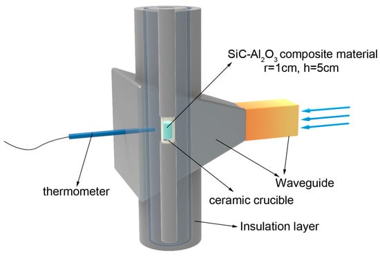
Figure 1.
Schematic diagram of internal structure of microwave heating.
The subject of this research revolves around Al2O3/SiC composites that undergo microwave heating. These composites were meticulously crafted through three pivotal steps: weighing, mixing, and die-casting. Both critical powders used in the process include α-alumina powder with an average particle size of 30 nanometers, and grayish-green silicon carbide powder featuring an average particle size of 50 nanometers were sourced from Zhongke New Material Technology Co. (Beijing, China).
The fabrication of Al2O3/SiC composites involves a well-defined process that ensures the uniform distribution and optimal properties of the final product. The key steps are as follows:
- Weighing: The first step involves accurately measuring and weighing the appropriate amounts of α-alumina powder and green silicon carbide powder. This is done in accordance with a predetermined mass ratio of 9:1 for Al2O3 to SiC, ensuring the desired composition of the composite.
- Mixing: The two powders are then poured into a crucible and thoroughly mixed by stirring. The mixing process continues until the powders blend into a homogeneous gray color, indicating a uniform distribution of the two materials.
- Die-casting: Once the powders are thoroughly mixed, they are die-cast into a cylinder using a cylindrical mold. The resulting cylinder has a height of 5 cm and a radius of 1 cm, providing a consistent shape and size for the composite.
The addition of silicon carbide to composites is particularly beneficial to the microwave heating process due to its strong microwave absorption properties. This allows silicon carbide to be used as a reinforcing material that effectively converts microwave energy into thermal energy and promotes rapid and uniform heating of the Al2O3/SiC composite cylinders.
3. Modeling
The microwave heating model of Al2O3/SiC composites was crafted utilizing COMSOL Multiphysics 5.6, a powerful software platform renowned for its ability to simulate complex physical phenomena through the finite element method. The details of model development are described in the following sections.
3.1. Model Assumptions
Indeed, discrepancies between the simulation model and the real-world counterpart are inherent due to the inherent complexities and limitations of modeling. To streamline the computational demands and facilitate efficient simulations, a series of idealized assumptions were incorporated into the model’s design. These key assumptions specifically encompass:
- Material Properties: The material properties are considered to be homogeneous and isotropic. This means that the physical properties (e.g., thermal conductivity, dielectric properties) are uniform throughout the material and do not vary with direction.
- Initial Temperature: The initial temperature of the model is assumed to be 293 K, which is a common choice for room temperature simulations.
- Microwave Reflection: The microwaves are assumed to be completely reflected by the walls of the cavity. This is a reasonable assumption for metal-lined cavities, which have high electrical conductivity and effectively prevent microwave penetration.
- Thermal Insulation: The boundaries of the whole system are assumed to be thermally insulated. This means that no heat is exchanged between the system and its surroundings, allowing the focus to be on the internal heating processes.
- No Sample Deformation: During the heating process, it is assumed that there is no deformation of the sample. This simplifies the analysis by eliminating the need to consider mechanical stresses and strains that might arise from temperature gradients or material expansion.
3.2. Geometric Model
The microwave heating apparatus is primarily comprised of three key components: a waveguide, a flare, and a cylindrical heating chamber. The microwave source directs transverse electromagnetic waves in TE10 mode through a rectangular waveguide into the resonant cavity, which operates as a multimode resonator, primarily structured by the flare and the cylindrical heating chamber. The cylindrical chamber, with a height of approximately 550 mm and a radius of roughly 75 mm, is stratified into four distinct layers: the mullite insulation layer I, refractory glass insulation, mullite insulation layer II and the heating layer. Within the center of the heating layer resides a crucible, dimensioned at 16 mm radius, 63 mm height, and 3 mm wall thickness. At the bottom of this crucible, a circular glass base, measuring 15 mm in radius and 5 mm in thickness, has been integrated. The Al2O3/SiC composite material, featuring a mass ratio of 9:1 for alumina to silicon carbide, is positioned on this glass base for heating purposes. Additionally, the upper and lower sections of the crucible are filled with mullite for insulation and support.
By symmetrizing the established model within COMSOL, the size of the model as well as the amount of computation can be reduced by half or even more, which is applicable when the geometry and model have symmetry. The geometry, material properties and boundary conditions of this microwave heating model are all based on the symmetry of the working plane, so the complete field distribution can be obtained by solving the field distribution on only one of the two sides of the symmetry plane, which effectively improves the efficiency of the model calculation. The symmetry division of the model is shown in Figure 2:
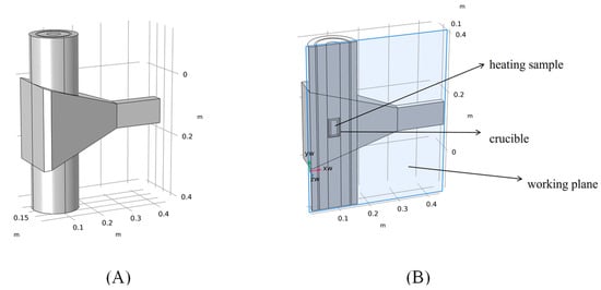
Figure 2.
(A) Full-size finite element model; (B) 1/2 full-size finite element model after work plane segmentation.
The electromagnetic and thermophysical attributes of air and metal wall have been pre-configured within COMSOL Multiphysics, allowing for their direct invocation. Table 1 presents the additional material parameters employed in the simulation process:

Table 1.
Electromagnetic and thermophysical parameters of the materials utilized in the simulation.
3.3. Electromagnetic Calculations
COMSOL Multiphysics uses approximate solutions of Maxwell’s system of equations to estimate the electromagnetic field distribution inside the resonant cavity. In this model, it is assumed that the wall cavity exhibits the behavior of a perfect conductor, effectively reflecting all incident microwaves without any loss. The microwaves are introduced into the system via a waveguide, operating in the TE10 mode, and the resultant electric field distribution within the resonant cavity is mathematically expressed as follows:
where E = electric field, ε0 = vacuum permittivity, k0 = wavenumber of free space, ω = angular frequency, μr = relative permeability, εr = relative permittivity, σ = electrical conductivity.
3.4. Thermal Calculations
In this simulation, the walls of the cavity are assumed to be perfect thermal barriers, preventing any heat exchange with the external environment and the initial temperature in all areas of the model is set to 293.15 K. Initially, the heat transfer behavior within the model are characterized by the application of the fundamental heat transfer equation:
where ρ = density, Cp = specific heat at constant pressure, and k = thermal conductivity.
Subsequently, a coupled electromagnetic-thermal model was formulated. This model integrates seamlessly within the COMSOL Multiphysics platform, leveraging its microwave heating multiphysics interface to couple solid heat transfer dynamics with the electromagnetic wave-frequency domain interface (RF module). This comprehensive approach considers the heat generated by various mechanisms, including resistive, dielectric, and magnetic losses that occur at high frequencies. Remarkably, the heating effect from the microwave’s magnetic field is minor compared to the dominant electric field component [25]. In this model, heat generated by electromagnetic thermal properties (Qe) is incorporated as a source, expressed as:
where J = σE, B = μ0μrH, and μ0 = vacuum permeability.
3.5. Boundary Conditions
For the model, boundary conditions have been established utilizing both the electromagnetic and heat transfer modules. The detailed configurations of these boundary conditions are outlined below:
An impedance boundary condition is applied to both the walls of the microwave cavity and the waveguide. This signifies that the electromagnetic field’s capacity to traverse these boundaries is virtually negligible. This phenomenon is mathematically elucidated through the subsequent equations:
where n represents the unit vector perpendicular to the metal boundary, and Es represents the electric field’s tangential component across the field’s interface.
The microwave injection end of the waveguide is assigned a port boundary condition, where the transverse electromagnetic (TE10) mode is specified to enable power delivery for microwave heating. This port boundary condition is defined by the equation:
where s represents an edge element, and ∂Ω signifies a small volume or, more specifically, a boundary surface that encloses or delimits that small volume.
To streamline the heat transfer computations within the model, the walls of the microwave cavity are designated as insulating boundary conditions. This configuration establishes that the heat flux across these boundaries is zero, effectively isolating the cavity from external thermal exchanges. This behavior is governed by the subsequent equations:
3.6. Mesh Setup
The model is meshed using a free tetrahedral mesh with flexibility and refinement adaptability for any 3D geometry. The cell size is optimised to have the highest average cell quality and the total number of cells is within acceptable limits to ensure efficiency and accuracy. The final meshing is shown in Figure 3:
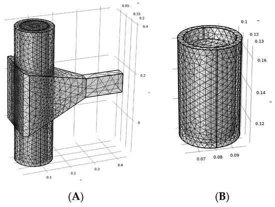
Figure 3.
(A) Three-dimensional model meshing diagram; (B) crucible and sample meshing diagram.
4. Results
In this chapter, the validity of the simulation model is firstly verified via practical experiments, and then the effects of different parameters on the microwave heating efficiency as well as the heating uniformity of Al2O3/SiC composites are specifically discussed in the following sections.
4.1. Model Validation
COMSOL Multiphysics has built-in physical parameters for air and ideal metal walls, and the physical parameters of the rest of the materials used in the model are given in Table 1. The electromagnetic–thermal multiphysics simulation step used in this model is frequency-domain-transient. In order to verify the validity of the simulation model, the power of the microwave source is set to 500 W, the frequency is set to 2.45 GHZ and a solver with a time step of 0.01 s is used to solve the distribution of the electromagnetic field in the cavity as well as the surface temperature data of the material. A total of 300 s of simulation is performed, and the temperature data of the specimen are output every 60 s. The temperature data of the specimen obtained from the actual experiment were compared with the simulation data, and the results are shown in Figure 4 below.
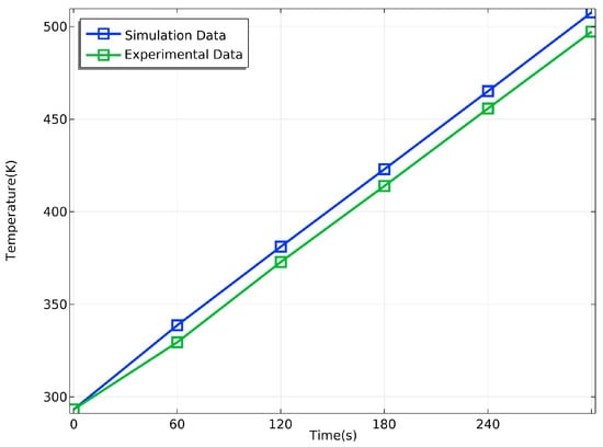
Figure 4.
Comparison of simulation and experimental data.
The accuracy of the model is now evaluated by calculating the Root Mean Square Error (RMSE) between the simulation and the experimental results, and the expression for the RMSE is given below:
where ST is the simulation temperature data, SM is the experimental measurement temperature data, and n is taken as 5 (sampling every 60 s interval, a total of 300 s measurements). Through the calculation, it can be obtained that in the specimen heated for 300 s, the RMSE of the model is about 1.863%. The consistency between the experimental data and the simulation data reflects the correctness and validity of this finite element model, so the parameter optimization scheme of this model can be applied in the actual experiment.
4.2. Effect of Microwave Power
Considering that the value of microwave input power is necessary in microwave heating, in this experiment, the heated SiC-Al3 composite material can be regarded as a load that can absorb the input power; the higher the input power, the faster the heating rate of the material will be. However, if the microwave input power used is too large, the heating quality of the material will be reduced, and the phenomenon of uneven heating in various parts will occur. In addition, if the microwave input power is too large, this will also cause a mismatch of resonant cavity loads, and microwave ovens working in such environments for long periods of time can suffer from excessive reflected power and eventual damage to the microwave source.
COMSOL Multiphysics is used to analyze the effect of microwave input power on the heating efficiency and heating uniformity of the sample, respectively. Three different input powers of 500 W, 750 W, and 1000 W were simulated for 10 min, and the distribution of the electric field on the surface of the material under three different input powers is shown in Figure 5:
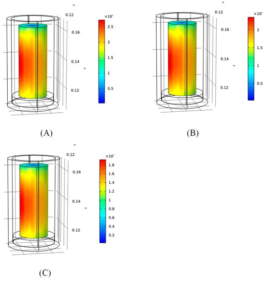
Figure 5.
The distribution of the electric field in the composite area at different input powers at 0 min: (A) 1000 W; (B) 750 W; (C) 500 W.
From Figure 5, it can be seen that the change in microwave power does not affect the electric field distribution law in the sample region, but only changes the magnitude of the electric field strength value in the sample region. As the microwave power increases, the field strength in the sample region also increases.
The heating rate and heating uniformity of the sample under three different input powers are simulated and analyzed. The heating rate is quantified by observing the change in the material’s average temperature over time, as depicted in Figure 6. Meanwhile, heating uniformity is evaluated by the ratio of the maximum temperature difference to the average temperature, with a ratio closer to 0 indicating superior heating uniformity, as exemplified in Figure 7.
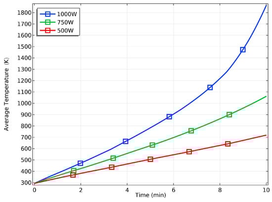
Figure 6.
Temperature rise curve of composites at different powers.
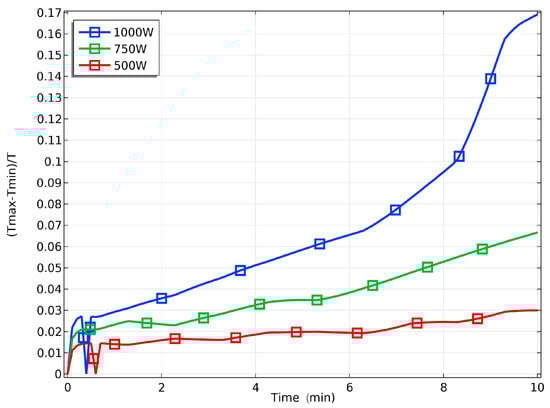
Figure 7.
Maximum temperature difference curve of the sample at different powers.
The Figure 6 show that the heating rate of the material when the input power is 1000 W is significantly higher than that when 750 W or 500 W is used; with a power of 1000 W, the sample reaches the temperature range required for the sintering process much faster. But at the same time, the maximum temperature difference inside the material is also increased, which ultimately affects the quality of material heating. Therefore, it is recommended that the heating of the material be carried out at a lower power, and the use of a lower power for heating can improve the uniformity of the material heating and reduce the energy consumption. The above results can be used to optimize the selection of the power parameters for practical experiments, so as to carry out rapid or uniform heating of the material.
4.3. Effect of Sample Geometry
It is also necessary to consider the effect of the geometry of the heated material on the heating efficiency, since the energy absorption of the microwave by the sample varies with the shape of the sample. Now, according to experiments on modeling sample geometry, in which two kinds of molds (a cylinder mold and a rectangular mold) are commonly used, it must be ensured that the total volume of material used in the two molds is equal, assuming that in these two shapes, the sample’s height is equal. The height of the sample is 50 mm, the radius of the cylinder sample is 10 mm, the bottom of the rectangular sample is 17.72 mm × 17.72 mm, and the microwave source power is set to 500 W. The two different shapes of samples were simulated for 20 min; the two samples’ field strength distributions are shown in Figure 8, and the temperature distribution is shown in Figure 9:
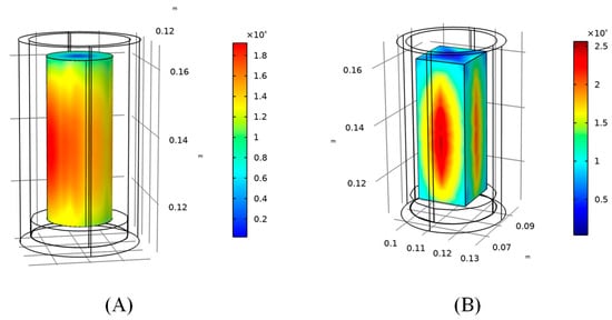
Figure 8.
The distribution of the electric field in the composite area for different geometries at 0 min: (A) cylinder sample; (B) rectangular sample.
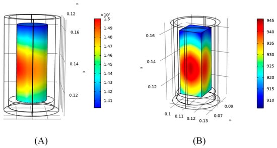
Figure 9.
Temperature field distribution in the composite area for different geometries at 20 min: (A) cylinder sample; (B) rectangular sample.
According to the simulation results, when the cylinder sample is used, the maximum value of the electric field intensity in the sample region is 2.01 × 10⁴ V/m, and the minimum value of the electric field intensity is 2.94 × 10² V/m; when the rectangular sample is used, the maximum value of the electric field intensity in the sample region is 2.51 × 10⁴ V/m, and the minimum value of the electric field intensity is 2.50 × 10² V/m. After 20 min of simulation, the average temperatures of the two were 1460.4 K and 929.72 K. When the average temperature of the sample reaches 900 K, the maximum temperature difference in the sample area is 40.53 K and 39.01 K in the two sample shapes. In summary, from the point of view of the heating rate, the temperature rise rate of the sample is faster when the cylindrical-shaped sample is used, and the temperature required for the sintering process can be reached in 20 min; from the point of view of heating uniformity, when the average temperature of the sample area reaches 900 K, the maximum temperature differences within the area of the two sample shapes are similar. Therefore, in general, the cylindrical sample is better than the rectangular sample.
4.4. Effects of Different Types of Crucibles
Different types of crucibles have different electromagnetic properties, and the use of different types of crucibles for holding samples for microwave heating will result in different electromagnetic field distributions in the heating chamber, which in turn affect the heating of samples. In this section, a simulation is carried out for the case of using two different crucible materials (an alumina ceramic crucible and a glass crucible), and the effect of using two different crucibles on the electric field distribution is analyzed. Here, the microwave source power is set to 500 W, and the simulation is carried out for 20 min for the two different crucibles; the electric field section diagrams for the two cases are shown in Figure 10, and the temperature distribution diagrams are as follows in Figure 11.
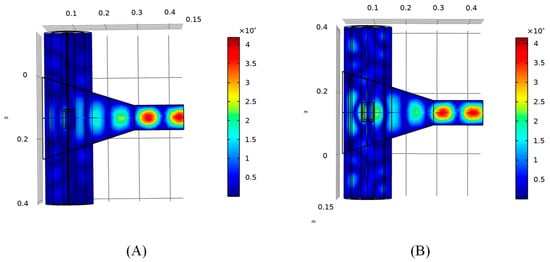
Figure 10.
Section of the electric field when two different types of crucibles are used at 0 min: (A) glass crucible; (B) alumina ceramic crucible.
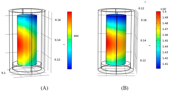
Figure 11.
Temperature distribution on the composite surface with two different crucibles at 20 min: (A) glass crucible; (B) alumina ceramic crucible.
According to the simulation results, it can be seen that the hot spot of electric field intensity at the center of the cavity almost disappears when a glass crucible is used, and the maximum value of the electric field intensity in the sample region is only 9.88 × 10³ V/m. The heating rate of the specimen is also greatly reduced. It is difficult to reach the temperature index of ceramic sintering in the specimen area when using a glass crucible, so it is not recommended to use a glass crucible to hold the sample for heating.
5. Conclusions
In this paper, a finite element model was established and simulated for the microwave heating process of SiC/Al2O3 composites using the COMSOL Multiphysics tool, and the validity of the simulation model was verified by comparing it with actual experiments. The time–temperature curves obtained from the sample simulation matched well with the actual experimental results, with the error within 2% or less. It can be seen through the simulation that microwave heating is sensitive to the choice of microwave power, sample shape and heating components.
- The value of the electric field increases with the increase in microwave power, and a high-power input will cause the generation of high heat and accelerate the temperature rise, but the thermal uniformity is relatively reduced.
- Different geometrical shapes of the sample affect the electric field distribution in the sample area, and in the case of the shapes with the same volume and height, the cylinder sample has a higher heating efficiency and quality.
- The electric field distribution in the heating chamber is highly sensitive to the choice of different material crucibles, and the value of the field strength at the center of the chamber is much larger in the case of an alumina ceramic crucible than in the case of a glass crucible, so it is not recommended to use a glass crucible to hold the sample for heating.
The above results were obtained based on COMSOL Multiphysics simulations and can be used to optimize the actual heating scheme for rapid or uniform heating of SiC/Al2O3 composites.
Author Contributions
G.L.: Conceptualization, Data Curation, Methodology, Software, Investigation, Formal Analysis, Validation, Writing—Original Draft; J.Z.: Conceptualization, Resources, Supervision, Validation, Writing—Review and Editing. All authors have read and agreed to the published version of the manuscript.
Funding
This research received no external funding.
Data Availability Statement
The authors confirm that the data supporting the findings of this study are available within the article.
Conflicts of Interest
The authors declare no conflicts of interest.
References
- Ramesh, P.D.; Brandon, D.; Schächter, L. Use of partially oxidized SiC particle bed for microwave sintering of low loss ceramics. Mater. Sci. Eng. A 1999, 266, 211–220. [Google Scholar] [CrossRef]
- Roy, R.; Agrawal, D.; Cheng, J.; Gedevanishvili, S. Full sintering of powdered-metal bodies in a microwave field. Nature 1999, 399, 668–670. [Google Scholar] [CrossRef]
- Rajkumar, K.; Aravindan, S. Microwave sintering of copper–graphite composites. J. Mater. Process. Technol. 2009, 209, 5601–5605. [Google Scholar] [CrossRef]
- Aravindan, S.; Krishnamurthy, R. Joining of ceramic composites by microwave heating. Mater. Lett. 1999, 38, 245–249. [Google Scholar] [CrossRef]
- Chandrasekaran, S.; Basak, T.; Ramanathan, S. Experimental and theoretical investigation on microwave melting of metals. J. Mater. Process. Technol. 2011, 211, 482–487. [Google Scholar] [CrossRef]
- Gupta, D.; Sharma, A.K. Development and microstructural characterization of microwave cladding on austenitic stainless steel. Surf. Coat. Technol. 2011, 205, 5147–5155. [Google Scholar] [CrossRef]
- Chen, M.; Siochi, E.J.; Ward, T.C.; McGrath, J.E. Basic ideas of microwave processing of polymers. Polym. Eng. Sci. 1993, 33, 1092–1109. [Google Scholar] [CrossRef]
- Oghbaei, M.; Mirzaee, O. Microwave versus conventional sintering: A review of fundamentals, advantages and applications. J. Alloys Compd. 2010, 494, 175–189. [Google Scholar] [CrossRef]
- Loharkar, P.K.; Ingle, A.; Jhavar, S. Parametric review of microwave-based materials processing and its applications. J. Mater. Res. Technol. 2019, 8, 3306–3326. [Google Scholar] [CrossRef]
- Iskander, M.F.; Smith, R.L.; Andrade, A.O.M.; Kimrey, H.; Wal, L.M. FDTD simulation of microwave sintering of ceramics in multimode cavities. IEEE Trans. Microw. Theory Tech. 1994, 42, 793–800. [Google Scholar] [CrossRef]
- Campañone, L.A.; Paola, C.A.; Mascheroni, R.H. Modeling and simulation of microwave heating of foods under different process schedules. Food Bioprocess Technol. 2012, 5, 738–749. [Google Scholar] [CrossRef]
- Kozlov, P.V.; Rafatov, I.R.; Kulumbaev, E.B.; Lelevkin, V.M. On modelling of microwave heating of a ceramic material. J. Phys. D Appl. Phys. 2007, 40, 2927. [Google Scholar] [CrossRef][Green Version]
- Shukla, A.K.; Mondal, A.; Upadhyaya, A. Numerical modeling of microwave heating. Sci. Sinter. 2010, 42, 99–124. [Google Scholar] [CrossRef]
- Ghorbel, I.; Ganster, P.; Moulin, N.; Meunier, C.; Bruchon, J. Experimental and numerical thermal analysis for direct mifigucrowave heating of silicon carbide. J. Am. Ceram. Soc. 2021, 104, 302–312. [Google Scholar] [CrossRef]
- Garnault, T.; Bouvard, D.; Chaix, J.M.; Marinel, S.; Harnois, C. Is direct microwave heating well suited for sintering ceramics? Ceram. Int. 2021, 47, 16716–16729. [Google Scholar] [CrossRef]
- Shi, J.; Cheng, Z.; Barriere, T.; Liu, B.; Gelin, J.C. Multiphysic coupling and full cycle simulation of microwave sintering applied to a ceramic compact obtained by ceramic injection moulding. Powder Metall. 2017, 60, 404–414. [Google Scholar] [CrossRef]
- Zhao, C.; Vleugels, J.; Groffils, C.; Luypaert, P.J.; Van der Biest, O. Hybrid sintering with a tubular susceptor in a cylindrical single-mode microwave furnace. Acta Mater. 2000, 48, 3795–3801. [Google Scholar] [CrossRef]
- Janney, M.A.; Calhoun, C.L.; Kimrey, H.D. Microwave sintering of solid oxide fuel cell materials: I, zirconia-8 mol% yttria. J. Am. Ceram. Soc. 1992, 75, 341–346. [Google Scholar] [CrossRef]
- Lasri, J.; Ramesh, P.D.; Schächter, L. Energy conversion during microwave sintering of a multiphase ceramic surrounded by a susceptor. J. Am. Ceram. Soc. 2000, 83, 1465–1468. [Google Scholar] [CrossRef]
- Ravi, B.G.; Praveen, V.; Selvam, M.P.; Rao, K.J. Microwave-assisted preparation and sintering of mullite and mullite–zirconia composites from metal organics. Mater. Res. Bull. 1998, 33, 1527–1536. [Google Scholar] [CrossRef]
- Leparoux, S.; Vaucher, S.; Beffort, O. Assessment of microwave heating for sintering of al/sic and for in-situ synthesis of tic. Adv. Eng. Mater. 2003, 5, 449–453. [Google Scholar] [CrossRef]
- Thakur, S.K.; Kong, T.S.; Gupta, M. Microwave synthesis and characterization of metastable (Al/Ti) and hybrid (Al/Ti + SiC) composites. Mater. Sci. Eng. A 2007, 452, 61–69. [Google Scholar] [CrossRef]
- Lin, B.Q.; Li, H.; Dai, H.M.; Zhu, C.J.; Yao, H. Three-dimensional simulation of microwave heating coal sample with varying parameters. Appl. Therm. Eng. 2016, 93, 1145–1154. [Google Scholar]
- Moon, E.M.; Yang, C.; Yakovlev, V.V. Microwave-induced temperature fields in cylindrical samples of graphite powder–experimental and modeling studies. Int. J. Heat Mass Transf. 2015, 87, 359–368. [Google Scholar] [CrossRef]
- Santos, T.; Valente, M.A.; Monteiro, J.; Sousa, J.; Costa, L.C. Electromagnetic and thermal history during microwave heating. Appl. Therm. Eng. 2011, 31, 3255–3261. [Google Scholar] [CrossRef]
Disclaimer/Publisher’s Note: The statements, opinions and data contained in all publications are solely those of the individual author(s) and contributor(s) and not of MDPI and/or the editor(s). MDPI and/or the editor(s) disclaim responsibility for any injury to people or property resulting from any ideas, methods, instructions or products referred to in the content. |
© 2024 by the authors. Licensee MDPI, Basel, Switzerland. This article is an open access article distributed under the terms and conditions of the Creative Commons Attribution (CC BY) license (https://creativecommons.org/licenses/by/4.0/).