Next Article in Journal
Optimizing Mean Estimators with Calibrated Minimum Covariance Determinant in Median Ranked Set Sampling
Previous Article in Journal
Anisotropic Scaling Non-Relativistic Holography: A Symmetry Perspective
 
 
Correction published on 26 February 2024, see Symmetry 2024, 16(3), 274.
Article

Nonequilibrium Casimir–Polder Interaction between Nanoparticles and Substrates Coated with Gapped Graphene

by
Galina L. Klimchitskaya
1,2,
Constantine C. Korikov
3,
Vladimir M. Mostepanenko
1,2,4,* and
Oleg Yu. Tsybin
2
1
Central Astronomical Observatory at Pulkovo of the Russian Academy of Sciences, 196140 Saint Petersburg, Russia
2
Peter the Great Saint Petersburg Polytechnic University, 195251 Saint Petersburg, Russia
3
Huawei Noah’s Ark Laboratory, Krylatskaya str. 17, 121614 Moscow, Russia
4
Kazan Federal University, 420008 Kazan, Russia
*
Author to whom correspondence should be addressed.
Symmetry 2023, 15(8), 1580; https://doi.org/10.3390/sym15081580
Submission received: 5 July 2023 / Revised: 8 August 2023 / Accepted: 9 August 2023 / Published: 13 August 2023 / Corrected: 26 February 2024
(This article belongs to the Section Physics)

Abstract

:
The out-of-thermal-equilibrium Casimir–Polder force between nanoparticles and dielectric substrates coated with gapped graphene is considered in the framework of the Dirac model using the formalism of the polarization tensor. This is an example of physical phenomena violating the time-reversal symmetry. After presenting the main points of the used formalism, we calculate two contributions to the Casimir–Polder force acting on a nanoparticle on the source side of a fused silica glass substrate coated with gapped graphene, which is either cooler or hotter than the environment. The total nonequilibrium force magnitudes are computed as a function of separation for different values of the energy gap and compared with those from an uncoated plate and with the equilibrium force in the presence of graphene coating. According to our results, the presence of a substrate increases the magnitude of the nonequlibrium force. The force magnitude becomes larger with higher and smaller with lower temperature of the graphene-coated substrate as compared to the equilibrium force at the environmental temperature. It is shown that, with increasing energy gap, the magnitude of the nonequilibrium force becomes smaller, and the graphene coating makes a lesser impact on the force acting on a nanoparticle from the uncoated substrate. Possible applications of the obtained results are discussed.

1. Introduction

Much use occurs of the physical systems whose parts are kept at different temperatures, i.e., in out-of-thermal-equilibrium conditions. The processes occurring in thermally nonequilibrium systems are usually irreversible, i.e., they lack the symmetry inherent in systems characterized by some unique temperature equal to that of the environment. The theoretical description of thermally nonequilibrium systems is a rather complicated subject. However, the demands of both fundamental physics and its applications in nanotechnology lent impetus to a successful search for new theoretical approaches.
Casimir–Polder interaction is an example of how the standard theory of a thermal equilibrium phenomenon can be extended to out-of-thermal-equilibrium conditions. Casimir and Polder [1] derived an expression for the force acting between a small polarizable particle and an ideal metal plane kept at zero temperature. In the framework of Lifshitz theory [2], this result was generalized to the case when an ideal metal plane is replaced with a thick-material plate kept at the same temperature T E as the environment [3,4]. The Casimir–Polder force is a thermally equilibrium quantum phenomenon determined by the zero-point and thermal fluctuations of the electromagnetic field. It finds extensive applications in atomic physics and condensed matter physics (see the monographs [5,6,7,8] for a large body of examples). Specifically, much attention is paid to the Casimir–Polder interaction between nanoparticles and material surfaces of different nature, including biomembranes [9,10,11,12,13,14,15,16,17,18].
The extension of Lifshitz theory to physical systems out of thermal equilibrium, which covers both cases of two macroscopic bodies and a small particle near the surface of a macroscopic body, was developed in [19,20,21,22,23,24] and further elaborated in [25,26,27,28,29,30,31,32]. This was completed under an assumption that each body is in the state of local thermal equilibrium [22]. The developed theory was confirmed experimentally by measuring the Casimir–Polder force between 87Rb atoms and a fused silica glass plate heated up to the temperatures much higher than T E [33]. The case when the dielectric properties of a plate depend heavily on the temperature offers a fertile field for the study of the nonequilibrium Casimir–Polder force. This is true for metallic plates [28,30] and for plates made of a material that undergoes phase transition with increasing temperature [29].
The material, which demonstrates a profound effect of temperature on its dielectric properties, is graphene, i.e., a one-atom-thick layer of carbon atoms packed in the hexagonal lattice [34]. At low energies, graphene is well-described by the Dirac model [35,36]. Due to its relatively simple structure, the spatially nonlocal dielectric properties of graphene can be expressed via the polarization tensor in (2 + 1) dimensions [37,38] and found on the solid basis of quantum electrodynamics at any temperature [39,40,41,42]. This presents the immediate possibility to calculate the Casimir–Polder force between nanoparticles and either heated or cooled graphene sheets using the extension of the Lifshits theory to the out-of-thermal-equilibrium situations. Calculations of this kind are of prime interest not only for fundamental physics but for numerous applications harnessing interaction of nanoparticles with graphene and graphene-coated substrates as well (see, e.g., [43,44,45,46,47,48]).
The investigation of the nonequilibrium Casimir–Polder interaction between nanoparticles and graphene originated in [49], where the freestanding in vacuum pristine graphene sheet was considered. The pristine character of graphene means that there is no energy gap in the spectrum of quasiparticles, i.e., they are massless, and it possesses the perfect crystal lattice with no foreign atoms. Both these assumptions are in the basis of the original Dirac model of graphene [34,35,36]. According to [49], the nanoparticles have the same temperature as the environment, whereas the graphene sheet may be either cooler or hotter than the environment, which takes the nanoparticle–graphene system out of the state of thermal equilibrium. It was shown [49] that the nonequilibrium conditions have a strong effect on the nanoparticle–graphene force and can even change the Casimir–Polder attraction with repulsion if the temperature of a graphene sheet is lower than T E .
Taking into account that real graphene sheets are characterized by some energy gap, i.e., small but nonzero mass of quasiparticles [34], an impact of the energy gap on the nonequilibrium Casimir–Polder force between a nanoparticle and a freestanding gapped graphene sheet was investigated in [50]. It was shown that, by varying the energy gap, it is possible to control the force value. Unlike the case of pristine graphene, the force acting on a nanoparticle from the sheet of gapped graphene preserves its attractive character.
When employing graphene sheets in physical experiments or in micro- and nanodevices, they are usually not freestanding in a vacuum but deposited on some dielectric substrate. Because of this, it is important to determine the impact of the substrate underlying the gapped graphene sheet on the nonequilibrium Casimir–Polder force acting on a nanoparticle. In this article, we investigate the force on a spherical nanoparticle from the source side of dielectric substrate coated with gapped graphene, which is either cooled or heated as compared to the environmental temperature T E . As to the temperature of nanoparticles, it is assumed to be equal to T E .
After presenting the main points of the theoretical formalism, we continue with a comparison between the equilibrium Casimir–Polder forces on a nanoparticle from the uncoated and coated with gapped graphene dielectric substrate. Then, the nonequilibrium Casimir–Polder force acting on a nanoparticle from an uncoated substrate is considered. Next, we turn our attention to the calculation of two contributions of different nature to the nonequilibrium force on a nanoparticle from the graphene-coated substrates with various values of the energy gap of graphene coating kept at different temperatures. Finally, the total nonequilibrium force on a nanoparticle is studied as the function of separation at different temperatures of a graphene-coated substrate and typical values of the energy gap.
It is shown that the presence of a substrate increases the magnitude of the nonequilibrium force, which is larger and smaller than the equilibrium one for a graphene substrate temperature higher and lower than T E , respectively. In all cases, an increase in the energy gap leads to smaller force magnitudes and to a lesser impact of the graphene coating on the nonequilibrium force on a nanoparticle from the uncoated dielectric substrate.
The article is organized as follows. Section 2 presents the necessary information from the theory of nonequilibrium Casimir–Polder force acting on nanoparticles from the substrates coated with gapped graphene. In Section 3, both the equilibrium and nonequilibrium forces on nanoparticles from the fused silica glass plate are considered and compared with the equilibrium one in the presence of graphene coating. In Section 4, the nonequilibrium Casimir–Polder force from a fused silica plate coated with gapped graphene is investigated. Section 5 contains the discussion. In Section 6, the reader will find our conclusions.

2. Theoretical Description of Nonequilibrium Casimir–Polder Interaction from Graphene-Coated Substrates

Here, we briefly present the formalism required for calculation of the Casimir–Polder force between nanoparticles and dielectric substrates coated with gapped graphene in out-of-thermal-equilibrium conditions. We assume that nanoparticles and the environment have the temperature T E (in computations, we use T E = 300 K), whereas the graphene-coated substrate has the temperature T g , which may be either lower or higher than T E . The separation distance between nanoparticles and the plane surface of area S of a graphene-coated substrate is a. The energy gap of a graphene coating is denoted Δ . Below, we consider the simplest case of spherical nanoparticles whose radius R satisfies the conditions
R a c k B T E , g ,
where k B is the Boltzmann constant. It is suggested also that a S .
Nanoparticles of arbitrary shape spaced at any separation from the surface, which should not be necessarily plane, can be considered using the more complicated scattering matrix approach [24,27].
It is convenient to represent the nonequilibrium Casimir–Polder force as a sum of two contributions [22,24]
F neq ( a , Δ , T E , T g ) = F M ( a , Δ , T E , T g ) + F r ( a , Δ , T E , T g ) .
Here, F M somewhat resembles the equilibrium Casimir–Polder force expressed as a sum over the discrete Matsubara frequencies, whereas F r is the proper nonequilibrium contribution.
Actually, both terms in Equation (2) describe some part of the effects of nonequilibrium and their explicit forms depend on which of the items responsible for these effects are included in F M and which in F r . Below, we employ F M and F r in the forms derived in [49] and used in [50]. Thus, F M has the form
F M ( a , Δ , T E , T g ) = 2 k B T E α ( 0 ) c 2 l = 0 0 k d k e 2 a q l ( k ) × 2 q l 2 ( k ) c 2 ξ E , l 2 R TM sub ( i ξ E , l , k , Δ , T g ) ξ E , l 2 R TE sub ( i ξ E , l , k , Δ , T g ) ,
where α ( 0 ) is the static polarizability of a nanoparticle, k is the component of the wave vector parallel to the plane of graphene, k = | k | , the prime on the sum divides the term with l = 0 by 2, and the Matsubara frequencies and q l are defined as
ξ E , l = 2 π k B T E l , q l 2 ( k ) = k 2 + ξ E , l 2 c 2 .
The quantities R TM , TE sub are the reflection coefficients of the electromagnetic waves on the graphene-coated substrate for the transverse magnetic and transverse electric polarizations. In fact, Equation (3) has the same form as the Lifshitz formula for the equilibrium Casimir–Polder force between a nanoparticle and a plate but with one important difference. Here, the Matsubara frequencies are defined at the environmental temperature T E but the reflection coefficients at the temperature of graphene-coated substrate T g (in the Lifshitz formula, T E = T g ). Note also that Equation (3) contains the static polarizability α ( 0 ) in front of the summation sign in l, whereas in the Lifshitz formula for an atom–wall interaction α ( i ξ l ) appears under the sum in l. This is because the dynamic polarizability of nanoparticles at several first Matsubara frequencies contributing to the force under the condition (1) reduces to α ( i ξ l ) α ( 0 ) [26].
The proper nonequilibrium contribution F r in Equation (2) is given by [49,50]
F r ( a , Δ , T E , T g ) = 2 α ( 0 ) π c 2 0 d ω Θ ( ω , T E , T g ) ω / c k d k e 2 a q ( ω , k ) × Im 2 q 2 ( ω , k ) c 2 + ω 2 R TM sub ( ω , k , Δ , T g ) + ω 2 R TE sub ( ω , k , Δ , T g ) ,
where
Θ ( ω , T E , T g ) = 1 exp ω k B T E 1 1 exp ω k B T g 1 , q 2 ( ω , k ) = k 2 ω 2 c 2 .
It is presented as an integral over the real frequency axis. In so doing, only k > ω / c , i.e., only the evanescent waves, contribute to Equation (5).
In the literature, the other forms of F M and F r have been considered, where F r contains contributions from both the evanescent and propagating waves [22]. The advantage of Equation (5) is a presence of the exponential factor with real q and negative power, which secures the quick convergence of the integral.
The reflection coefficients on the graphene-coated substrate were expressed via the frequency-dependent dielectric permittivity of substrate ε ( ω ) and the polarization tensor of graphene Π m n ( ω , k , Δ , T g ) in (2 + 1) dimensions, i.e., with m , n = 0 , 1 , 2 [51].
R TM sub ( ω , k , Δ , T g ) = k 2 [ ε ( ω ) q ( ω , k ) q ε ( ω , k ) ] + q ( ω , k ) q ε ( ω , k ) Π 00 ( ω , k , Δ , T g ) k 2 [ ε ( ω ) q ( ω , k ) + q ε ( ω , k ) ] + q ( ω , k ) q ε ( ω , k ) Π 00 ( ω , k , Δ , T g ) , R TE sub ( ω , k , Δ , T g ) = k 2 [ q ( ω , k ) q ε ( ω , k ) ] Π ( ω , k , Δ , T g ) k 2 [ q ( ω , k ) + q ε ( ω , k ) ] + Π ( ω , k , Δ , T g ) ,
where
q ε 2 ( ω , k ) = k 2 ε ( ω ) ω 2 c 2 , Π ( ω , k , Δ , T g ) = k 2 Π m m ( ω , k , Δ , T g ) q 2 ( ω , k ) Π 00 ( ω , k , Δ , T g ) .
For an uncoated substrate Π 00 = Π = 0 and Equation (7) transforms into the familiar Fresnel reflection coefficients. To obtain the reflection coefficients at the pure imaginary frequencies entering Equation (3), one should put in Equation (7) ω = i ξ E , l . Here, we also assume that the dielectric permittivity of a substrate material does not depend on temperature, contrary to the polarization tensor of graphene. In the case of materials (metals, for instance) with temperature-dependent dielectric permittivity, one should change ε ( ω ) in Equation (7) with ε ( ω , T g ) .
Computations of the nonequilibrium Casimir–Polder force between nanoparticles and graphene-coated substrate can be performed by Equations (2), (3), (5), and (7) if one knows the explicit expressions for the components of the polarization tensor of graphene. For the gapped graphene, these components defined along both real and imaginary frequency axes were found in [41] and presented more specifically in [49,50] in terms of the variables ω and k. It should be noted, however, that the numerical computations of Equation (5) along the real frequency axis for substrates coated with gapped graphene are much more involved than those of Equation (3) and should be performed using the convenient choice of dimensionless variables. That is why, below we introduce the necessary dimensionless quantities and present the results (5)–(8) and the expressions for the dimensionless polarization tensor in these terms.
Let us define the following dimensionless quantities
t = c k ω , q ˜ ( t ) = t 2 1 = c ω q ( ω , k ) , q ˜ ε ( ω , t ) = t 2 ε ( ω ) = c ω q ε ( ω , k ) , Π ˜ 00 ( t , Δ ˜ , τ g ) = c ω t 2 Π 00 ( ω , k , Δ , T g ) , Π ˜ ( t , Δ ˜ , τ g ) = c 3 ω 3 t 2 Π ( ω , k , Δ , T g ) ,
where
Δ ˜ = Δ ω , τ g = ω k B T g .
Using Equations (9) and (10), the reflection coefficients of Equation (7) can be rewritten as
R TM sub ( ω c x , t , Δ ˜ , τ g ) = ε ( ω c x ) q ˜ ( t ) q ˜ ε ( ω c x , t ) + q ˜ ( t ) q ˜ ε ( ω c x , t ) Π ˜ 00 ( t , Δ ˜ , τ g ) ε ( ω c x ) q ˜ ( t ) + q ˜ ε ( ω c x , t ) + q ˜ ( t ) q ˜ ε ( ω c x , t ) Π ˜ 00 ( t , Δ ˜ , τ g ) , R TE sub ( ω c x , t , Δ ˜ , τ g ) = q ˜ ( t ) q ˜ ε ( ω c x , t ) Π ˜ ( t , Δ ˜ , τ g ) q ˜ ( t ) + q ˜ ε ( ω c x , t ) + Π ˜ ( t , Δ ˜ , τ g ) ,
where
x = ω ω c ( a ) , ω c ( a ) = c 2 a .
Below in this section, we rewrite the results of [41,50] for the polarization tensor in the region of evanescent waves in terms of dimensionless variables (9) and (10). It is common to present the polarization tensor as the sum of two contributions
Π ˜ 00 ( t , Δ ˜ , τ g ) = Π ˜ 00 ( 0 ) ( t , Δ ˜ ) + Π ˜ 00 ( 1 ) ( t , Δ ˜ , τ g ) , Π ˜ ( t , Δ ˜ , τ g ) = Π ˜ ( 0 ) ( t , Δ ˜ ) + Π ˜ ( 1 ) ( t , Δ ˜ , τ g ) .
The first terms on the right-hand side of Equation (13) refer to the case of zero temperature, whereas the second have the meaning of the thermal corrections to them. The polarization tensor in the area of evanescent waves k > ω / c has different forms in the so-called plasmonic region [52]
ω c < k < ω v F , 1 < t < 1 v ˜ F 300
and in the region
k > ω v F , t > 1 v ˜ F 300 ,
where v F c / 300 is the Fermi velocity for graphene and v ˜ F = v F / c .
We begin with the plasmonic region (14). Here, the polarization tensor is also defined differently depending on the fulfilment of some condition. Thus, if the following inequality is satisfied:
Δ ˜ 1 v ˜ F 2 t 2 > 1 ,
the first contributions to the polarization tensor in Equation (13) are given by
Π ˜ 00 ( 0 ) ( t , Δ ˜ ) = 2 α 1 v ˜ F 2 t 2 Φ A Δ ˜ 1 v ˜ F 2 t 2 , Π ˜ ( 0 ) ( t , Δ ˜ ) = 2 α 1 v ˜ F 2 t 2 Φ A Δ ˜ 1 v ˜ F 2 t 2 ,
where α = e 2 / ( c ) is the fine structure constant and
Φ A ( x ) = x ( 1 + x 2 ) arctanh 1 x .
Under the condition of Equation (16), the second contributions to Equation (13) take the form
Π ˜ 00 ( 1 ) ( t , Δ ˜ , τ g ) = 8 α v ˜ F 2 t 2 Δ ˜ d z Ψ ( z , τ g ) 1 1 2 1 v ˜ F 2 t 2 λ = ± 1 λ ( z + λ ) 2 v ˜ F 2 t 2 ( z + λ ) 2 v ˜ F 2 t 2 A ( Δ ˜ , t ) , Π ˜ ( 1 ) ( t , Δ ˜ , τ g ) = 8 α v ˜ F 2 t 2 Δ ˜ d z Ψ ( z , τ g ) 1 1 2 1 v ˜ F 2 t 2 λ = ± 1 λ ( z + λ ) 2 v ˜ F 2 t 2 [ 1 A ( Δ ˜ , t ) ] ( z + λ ) 2 v ˜ F 2 t 2 A ( Δ ˜ , t ) ,
where
A ( Δ ˜ , t ) = 1 Δ ˜ 2 1 v ˜ F 2 t 2 , Ψ ( z , τ g ) = 1 e τ g z + 1 .
From Equations (17) and (19), it is observed that, under inequality (16), the polarization tensor is real.
Next, we continue the consideration of the plasmonic region (14) but under the inequality opposite to Equation (16)
Δ ˜ 1 v ˜ F 2 t 2 < 1 .
In this case, the first contributions to the polarization tensor (13) take the form
Π ˜ 00 ( 0 ) ( t , Δ ˜ ) = 2 α 1 v ˜ F 2 t 2 Φ B Δ ˜ 1 v ˜ F 2 t 2 , Π ˜ ( 0 ) ( t , Δ ˜ ) = 2 α 1 v ˜ F 2 t 2 Φ B Δ ˜ 1 v ˜ F 2 t 2 ,
where
Φ B ( x ) = x ( 1 + x 2 ) arctanh x + i π 2 .
The second contributions to Equation (13) under inequality (21) take a more complicated form
Π ˜ 00 ( 1 ) ( t , Δ ˜ , τ g ) = 8 α v ˜ F 2 t 2 Δ ˜ z ( ) d z Ψ ( z , τ g ) 1 1 2 1 v ˜ F 2 t 2 λ = ± 1 ( z + λ ) 2 v ˜ F 2 t 2 ( z + λ ) 2 v ˜ F 2 t 2 A ( Δ ˜ , t ) + z ( ) d z Ψ ( z , τ g ) 1 1 2 1 v ˜ F 2 t 2 λ = ± 1 λ ( z + λ ) 2 v ˜ F 2 t 2 ( z + λ ) 2 v ˜ F 2 t 2 A ( Δ ˜ , t ) , Π ˜ ( 1 ) ( t , Δ ˜ , τ g ) = 8 α v ˜ F 2 t 2 Δ ˜ z ( ) d z Ψ ( z , τ g ) 1 1 2 1 v ˜ F 2 t 2 λ = ± 1 ( z + λ ) 2 v ˜ F 2 t 2 [ 1 A ( Δ ˜ , t ) ] ( z + λ ) 2 v ˜ F 2 t 2 A ( Δ ˜ , t ) + z ( ) d z Ψ ( z , τ g ) 1 1 2 1 v ˜ F 2 t 2 λ = ± 1 λ ( z + λ ) 2 v ˜ F 2 t 2 [ 1 A ( Δ ˜ , t ) ] ( z + λ ) 2 v ˜ F 2 t 2 A ( Δ ˜ , t ) ,
where
z ( ) = z ( ) ( t , Δ ˜ ) = 1 v ˜ F t A ( Δ ˜ , t ) .
Note that the polarization tensor in the plasmonic region under inequality (21) is the complex quantity. The first contributions to Equation (13) defined in Equation (22) are complex due to Equation (23). As to the second contributions to Equation (13) defined in Equation (24), they are complex due to the square root in the denominators of Equation (24), which have an imaginary part in the z interval near z ( ) . Much care must be taken regarding this interval in numerical computations.
We come now to the region (15) and rewrite the results of [41,50] for the polarization tensor in terms of the dimensionless quantities (9) and (10). In this region, the first contributions to Equation (13) are
Π ˜ 00 ( 0 ) ( t , Δ ˜ ) = 2 α v ˜ F 2 t 2 1 χ Δ ˜ v ˜ F 2 t 2 1 , Π ˜ ( 0 ) ( t , Δ ˜ ) = 2 α v ˜ F 2 t 2 1 χ Δ ˜ v ˜ F 2 t 2 1 ,
where
χ ( x ) = x + ( 1 x 2 ) arctan 1 x .
The second contributions to Equation (13) in the region (15) are expressed as
Π ˜ 00 ( 1 ) ( t , Δ ˜ , τ g ) = 8 α v ˜ F 2 t 2 Δ ˜ d z Ψ ( z , τ g ) 1 + 1 2 λ = ± 1 λ v ˜ F 2 t 2 ( z + λ ) 2 [ v ˜ F 2 t 2 ( z + λ ) 2 ] ( v ˜ F 2 t 2 1 ) + v ˜ F 2 t 2 Δ ˜ 2 , Π ˜ ( 1 ) ( t , Δ ˜ , τ g ) = 8 α v ˜ F 2 t 2 Δ ˜ d z Ψ ( z , τ g ) 1 + 1 2 λ = ± 1 λ ( z + λ ) 2 ( v ˜ F 2 t 2 1 ) v ˜ F 2 t 2 Δ ˜ 2 [ v ˜ F 2 t 2 ( z + λ ) 2 ] ( v ˜ F 2 t 2 1 ) + v ˜ F 2 t 2 Δ ˜ 2 ,
From Equations (26) and (28), it is observed that in the region (15) the first contributions to the polarization tensor, Π ˜ 00 ( 0 ) and Π ˜ ( 0 ) , are real whereas the second, Π ˜ 00 ( 1 ) and Π ˜ ( 1 ) , are complex.
In the end of this section, we rewrite the proper nonequilibrium contribution (5) to the Casimir–Polder force in terms of the dimensionless variables (9), (10), and (12)
F r ( a , Δ , T E , T g ) = c α ( 0 ) 16 π a 5 0 d x x 4 Θ ( τ E , τ g ) 1 t d t e x t 2 1 × Im ( 2 t 2 1 ) R TM sub ( ω c x , t , Δ ˜ , τ g ) + R TE sub ( ω c x , t , Δ ˜ , τ g ) ,
where
Θ ( τ E , τ g ) = 1 e τ E 1 1 e τ g 1 , τ E , g τ E , g ( ω c x ) = ω c x k B T E , g
and the reflection coefficients R TM , TE sub expressed via the dimensionless variables are contained in Equation (11).

3. Equilibrium and Nonequilibrium Casimir–Polder Forces from Fused Silica Plate Compared to Equilibrium Force in the Presence of Graphene Coating

In this and in the next sections, we use the formalism presented in Section 2 for numerical computations of the Casimir–Polder force acting on a nanoparticle on the source side of the graphene-coated substrate. As the substrate material, we choose fused silica glass, SiO 2 , which is often used both in applications of graphene in nanoelectronics [53,54,55,56] and in physical experiments on measuring the Casimir force [57,58].
For better understanding of the relative roles of substrate, of nonequilibrium effects, and of graphene coating, in this section we start from calculation of the equilibrium Casimir–Polder forces acting on nanoparticles from the uncoated and coated with gapped graphene SiO 2 substrate. Next, the nonequilibrium force from an uncoated SiO 2 substrate will be computed.
The equilibrium Casimir–Polder force acing on a nanoparticle from both uncoated and graphene-coated SiO 2 substrates is given by Equation (3),
F eq ( a , Δ , T E ) = F M ( a , Δ , T E , T E ) ,
where we put T E = T g .
If the substrate is uncoated, the reflection coefficients R TM , TE sub are given by Equation (7), where ω = i ξ E , l and Π 00 = Π = 0 . If the substrate is coated with graphene, one should use Equation (7) with T g = T E . In this case, the polarization tensor of graphene is given by expressions (26) and (28) found in the frequency region (15), where, after returning to the dimensional variables, one can immediately put ω = i ξ E , l (the explicit expressions for the polarization tensor of graphene at the pure imaginary frequencies i ξ E , l are contained in [59]).
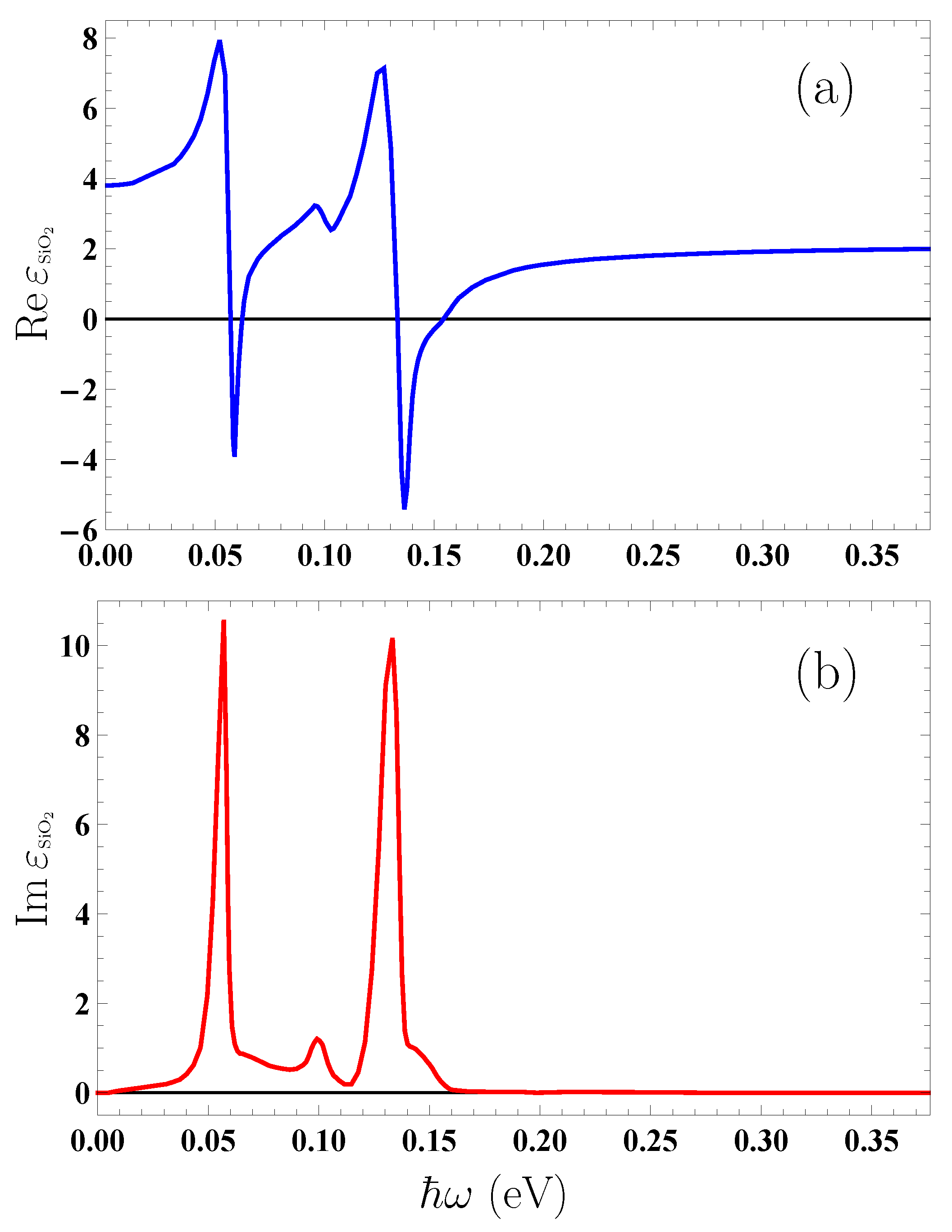
Computations of the equilibrium force F eq and the contribution F M to the nonequilibrium force require the dielectric permittivity of SiO 2 along the imaginary frequency axis at our disposal, whereas computations of the contribution F r to the nonequilibrium force require ε SiO 2 ( ω ) along the axis of real frequencies. In Figure 1, we present the real (a) and imaginary (b) parts of the dielectric permittivity of SiO 2 along the real frequency axis plotted by the tabulated optical data for the complex index of refraction of SiO 2 [60]. The data collected in [60] extend from 0.0025 to 2000 eV, whereas in Figure 1 the most important region for our computations is presented. The values of the dielectric permittivity along the imaginary frequency axis are obtained from Im ε SiO 2 by means of the Kramers–Kronig relations and can be found in many literature sources (see, e.g., [7]).
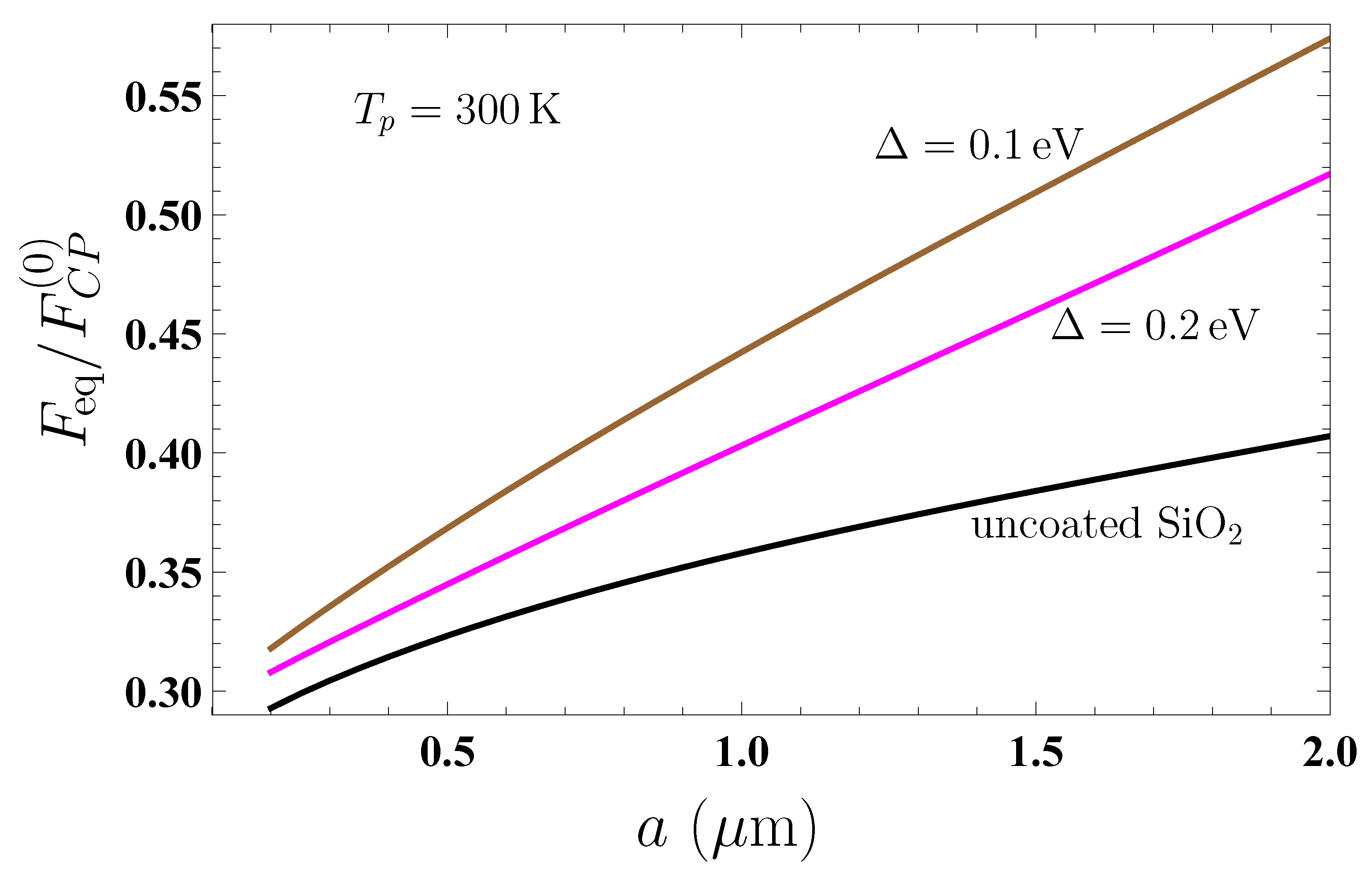
Now, we compute the equilibrium Casimir–Polder force (31) acting on a nanoparticle from either an uncoated or graphene-coated SiO 2 plate as a function of separation at the plate temperature T p = T E = 300 K. Keeping in mind that the force values strongly depend on separation, we normalize them to the Casimir–Polder force on a nanoparticle from the ideal metal plane at zero temperature [7]
F C P ( 0 ) ( a ) = 3 c 2 π a 5 α ( 0 ) .
Taking into account that the Dirac model is applicable at energies below 3 eV [61], we consider the nanoparticle–plate separations exceeding 200 nm where the characteristic energy ω c is much less than 3 eV. From the above, we restrict the separation region by 2 μ m, where the condition (1) is yet applicable.
In Figure 2, the computational results for F eq / F C P ( 0 ) at T p = T E = 300 K are shown as the function of separation by the three lines counted from bottom to top for an uncoated SiO 2 plate and for coated by a graphene sheet with the energy gap Δ = 0.2 eV and 0.1 eV, respectively (in the two latter cases, the temperature of graphene is T g = T p = T E ). As shown in Figure 2, the presence of graphene coating increases the magnitude of the Casimir–Polder force acting on a nanoparticle. This increase, however, is larger for a graphene sheet with smaller energy gap.
To obtain the absolute values of force acting on a nanoparticle, one can use the data of Figure 2 in combination with the following expressions for the static polarizabilities:
α ( 0 ) = R 3 ε ( 0 ) 1 ε ( 0 ) + 2 , α ( 0 ) = R 3 ,
which are valid for dielectric and metallic nanoparticles, respectively [26]. Thus, for SiO 2 one obtains ε ( 0 ) = 3.81 from Figure 1a.
Now, we calculate the nonequilibrium Casimir–Polder force F neq SiO 2 acting on a nanoparticle from the uncoated SiO 2 plate. In so doing, we assume that the plate temperature is either lower, T p = 77 K, or higher, T p = 500 K, than the environmental temperature T E = 300 K. The computations are performed by Equations (2), (3), and (29) with the reflection coefficients (7), where Π 00 = Π = 0 in the absence of graphene coating.
Note that the computation of the proper nonequilibrium contribution F r to the nonequlibrium Casimir–Polder force, which is performed along the real frequency axis, is much more labor- and time-consuming, especially in the presence of graphene coating (see the next section). These computations were realized by using a program written in the C++ programming language [50] at the Supercomputer Center of the Peter the Great Saint Petersburg Polytechnic University.
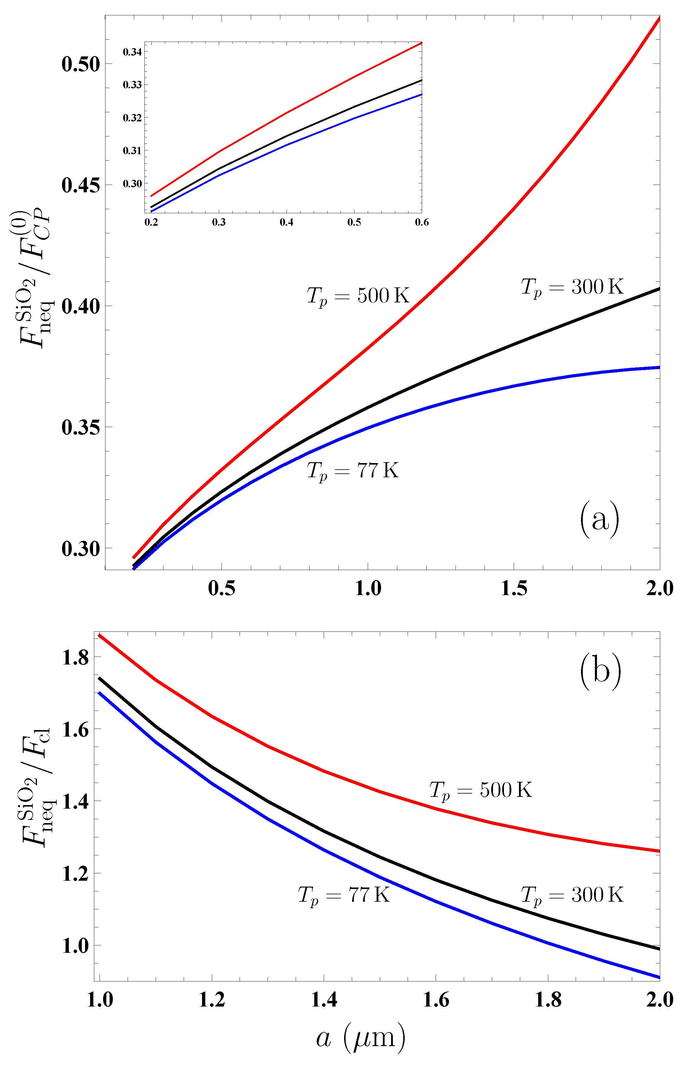
In Figure 3a, we present the computational results for the ratio F neq SiO 2 / F C P ( 0 ) as the function of separation by the bottom and top lines for the plate temperatures T p = 77 K and 500 K, respectively. For comparison purposes, the equilibrium Casimir–Polder force ratio F eq SiO 2 / F C P ( 0 ) for a plate kept at the environmental temperature T p = T E = 300 K is shown by the middle line, which reproduces the bottom line from Figure 2. In the inset, the region of small separations from 0.2 to 0.6 μ m is shown on an enlarged scale for better visualization.
From Figure 3a, it is seen that the effects of nonequilibrium have a strong impact on the equilibrium Casimir–Polder force from a SiO 2 plate, making its magnitude larger if T p > T E and smaller if T p < T E . From Figure 3a, one can also see that at separations exceeding 1 μ m the Casimir–Polder force (32) from an ideal metal plane poorly reproduces the dependence of the nonequilibrium force on the separation distance. Because of this, in the region from 1 to 2 μ m, we consider the same computational results for F neq SiO 2 but normalize them to the thermal Casimir–Polder force from an ideal metal plane at large separations (the so-called classical limit) [7]
F cl ( a , T E ) = 3 k B T E 4 a 4 α ( 0 ) .
In Figure 3b, the computational results for the ratio F neq SiO 2 / F cl are shown as the function of separation by the bottom and top lines for the plate temperatures T p = 77 K and 500 K, respectively. The middle line demonstrates the ratio F eq SiO 2 / F cl in the case of thermal equilibrium T p = T E = 300 K. Figure 3b confirms the conclusions already drawn from Figure 3a. It is also observed that the effects of nonequilibrium due to higher temperature than the environmental one have a greater impact on the equilibrium force than those due to a decrease in temperature to below the environmental one. Further decrease in temperature to below 77 K leads to only an insignificant decrease in the magnitude of nonequilibrium Casimir–Polder force.

4. Nonequilibrium Casimir–Polder Force from Fused Silica Plate Coated with Gapped Graphene

In the previous section, we already considered the nonequilibrium Casimir–Polder force from a SiO 2 plate. The main difference in the case of a graphene-coated plate considered now is that the response of graphene to the electromagnetic field described by the polarization tensor strongly depends on temperature. This is not the case for a SiO 2 plate whose dielectric permittivity is temperature-independent. As a result, for an uncoated SiO 2 plate, the effects of nonequilibrium influence the force only through the factor Θ in Equation (5) defined in Equation (6).
According to Equation (2), the total nonequilibrium force is the sum of two contributions, F M and F r . The first of them has the same form as the equilibrium Casimir–Polder force, whereas the second is the proper nonequilibrium contribution. In order to understand physics of the process, we consider each of them separately starting from F M (for an uncoated SiO 2 plate, F M is equal to the equilibrium force at T = 300 K shown by the bottom line in Figure 2 for any temperature of the plate).
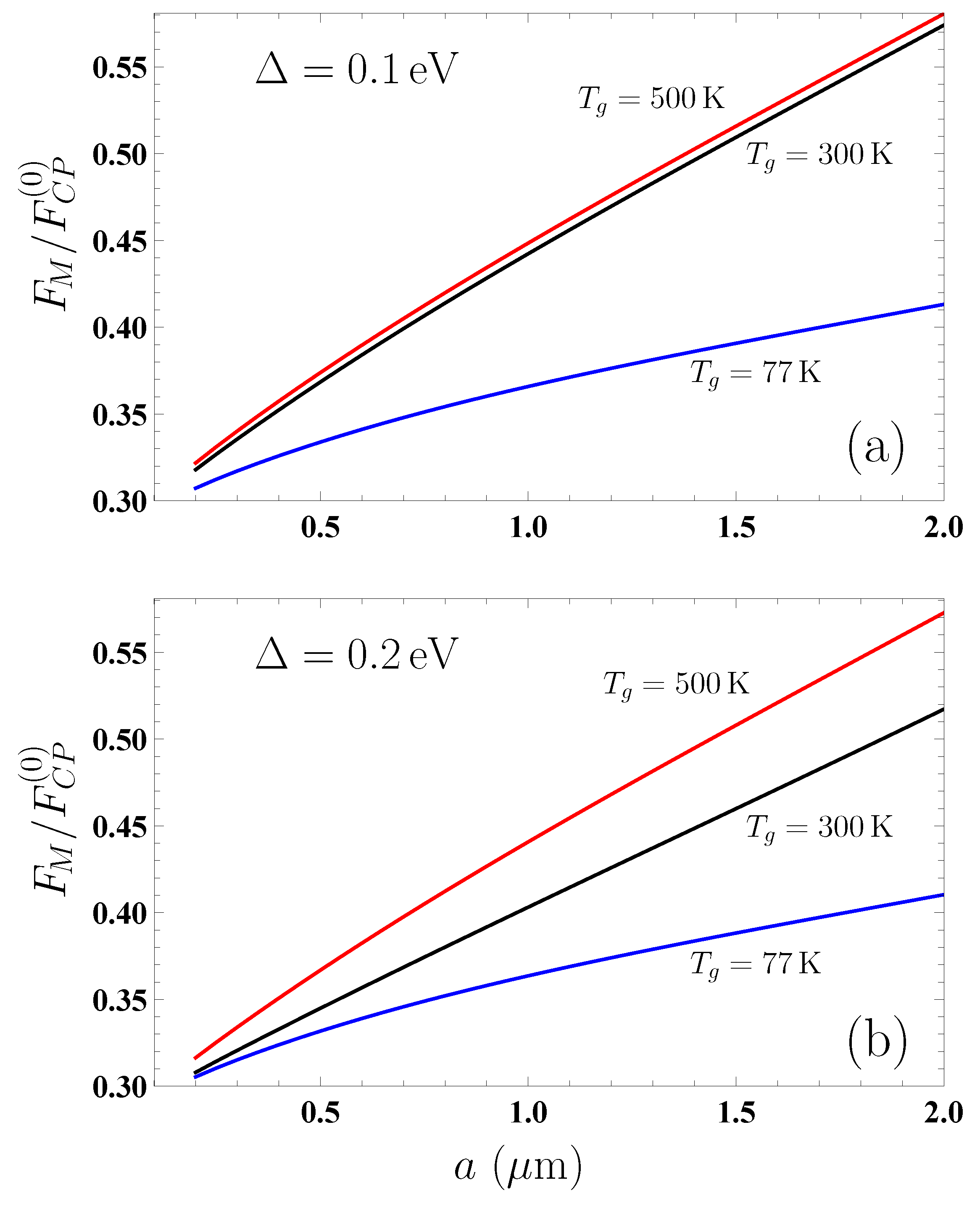
Computations of F M were performed by Equations (3) and (7) and the polarization tensor defined at the pure imaginary frequencies i ξ E , i (see Section 3 and [59]). The computational results for the ratio F M / F C P ( 0 ) are presented in Figure 4a,b as the function of separation for (a) graphene coating with the energy gap Δ = 0.1 eV and (b) graphene coating with Δ = 0.2 eV by the bottom and top lines plotted for the graphene (and plate) temperatures T p = 77 K and 500 K. The middle line shows the ratio F eq / F C P ( 0 ) when the graphene temperature is equal to that of the environment, T g = T E = 300 K.
Unlike the case of an uncoated SiO 2 plate, in the presence of graphene coating F M is not equal to the equilibrium force at T g = T E = 300 K. As shown in Figure 4a, for the relatively small energy gap of the graphene coating Δ = 0.1 eV, the quantity F M at T g = 500 K differs little from the equilibrium force at T g = T E = 300 K over the entire separation region from 0.2 to 2 μ m. Thus, the relative deviation
δ F M ( a , Δ , T E , T g ) = F M ( a , Δ , T E , T g ) F eq ( a , Δ , T E , T g ) F eq ( a , Δ , T E , T g )
varies in this case from 1.21% at a = 0.2 μ m to 1.14% at a = 2 μ m, i.e., is almost independent on separation.
From Figure 4a, it is also observed that both the middle and top lines grow with separation. This means that, for a substrate coated by graphene with Δ = 0.1 eV, considerable contribution to both F M at T g = 500 K and F eq at T g = T E = 300 K is given by the term of the Lifshitz formula with l = 0 . At the same time, for a graphene coating with Δ = 0.1 eV at T g = 77 K, the deviation of F M from F eq is much larger and it increases with increasing separation (see the bottom and middle lines in Figure 4a). Thus, at a = 0.2 μ m we have δ F M = 3.35 % and at a = 2 μ m already δ F M = 28 %.
The comparison of Figure 4a plotted for a graphene coating with Δ = 0.1 eV with Figure 4b plotted for Δ = 0.1 eV shows that the values of F M computed at T g = 77 K almost coincide (the difference of 0.6% at a = 0.2 μ m and 1% at a = 2 μ m). This means that at the relatively low T g = 77 K the thermal corrections are rather small and depend only slightly on the value of Δ in the range of separations from 0.2 to 2 μ m. The comparison of the values of F M at T g = 500 K for graphene coatings with Δ = 0.1 and 0.2 eV (top lines in Figure 4a,b) also demonstrates rather small deviations (1% at a = 0.2 μ m and 1.9% at a = 2 μ m). This is because at such high temperature the thermal corrections are rather large and have only a weak dependence on Δ . As to the equilibrium Casimir–Polder force at T g = T E = 300 K, it depends on Δ more distinctly (compare with Figure 2). Note also that the magnitudes of F M at both 77 K and 500 K are larger than the magnitudes of F neq from an uncoated SiO 2 plate at the same respective temperatures. This is observed from the comparison of Figure 4a,b and Figure 3.
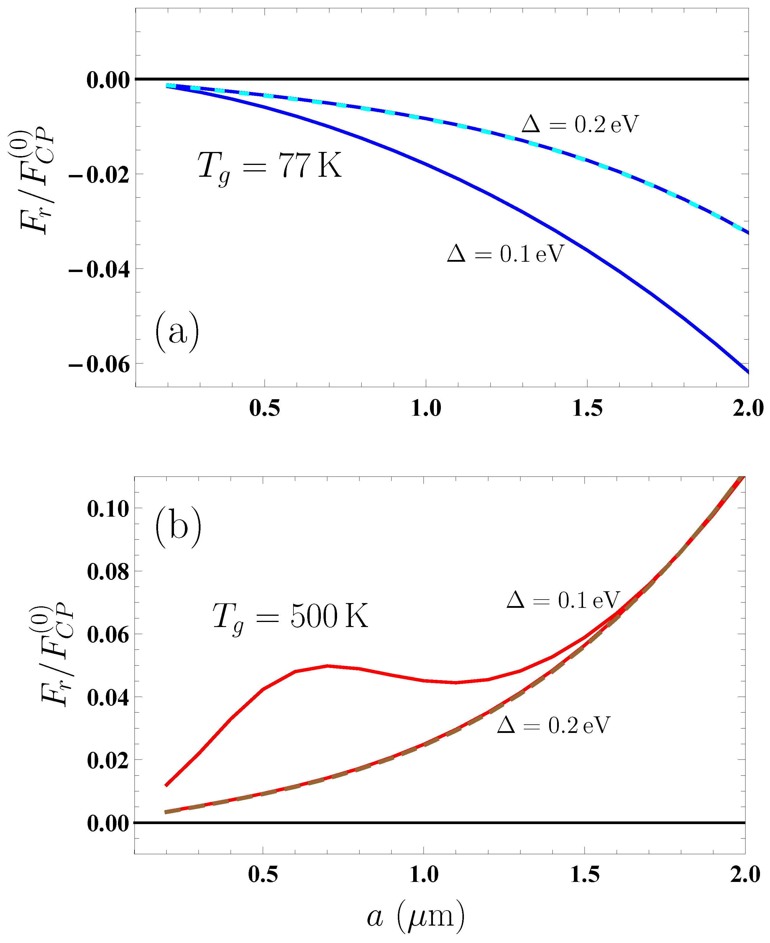
Next, we consider the second contribution, F r , to the nonequilibrium Casimir–Polder force (2) acting on a nanoparticle from a graphene-coated substrate. The numerical computations of F r were performed in the dimensionless variables by Equations (11) and (29) using the polarization tensor in Equations (17), (19), (22), (24), (26), and (28). The computational results for the ratio F r / F C P ( 0 ) are presented in Figure 5 as the function of separation for (a) graphene plate temperature T g = 77 K and (b) graphene plate temperature T g = 500 K. The solid line in Figure 5a is plotted for a graphene coating with Δ = 0.1 eV, whereas another (dashed) line presents the coinciding results for the graphene coating with Δ = 0.2 eV and for the uncoated SiO 2 plate. The top and bottom solid lines in Figure 5b are for a graphene coating with Δ = 0.1 and 0.2 eV, respectively, and the dashed line is for the uncoated SiO 2 plate. The form of presentation in Figure 5a,b provides a way to determine the comparative contributions of the regions (14) and (15) to F r .
As shown in Figure 5a,b, the quantity F r , unlike F M , substantially depends on the value of Δ at both T g = 77 and 500 K. The point is that, for T g < T E , the contributions to F r from the regions (14) and (15) are positive, i.e., decrease the force magnitude. The opposite situation occurs for T g > T E , i.e., the contributions of Equations (14) and (15) to F r are negative, leading to the increase in force magnitude.
For the nonequilibrium Casimir–Polder force acting on a nanoparticle from a freestanding in vacuum graphene sheet, different contributions to F r were investigated in [50]. It was shown that for a graphene with Δ = 0.2 eV at T g = 77 K it holds F r 0 , whereas for Δ = 0.1 eV the main contribution to F r is given by the region of (15), which leads to the increase in the force magnitude. If the graphene with Δ = 0.1 eV is heated up to T g = 500 K, at short separations ( a 0.4 μ m) the contribution from the region of (15) is dominant. With increasing separation, however, the region (14) takes the main role leading to a minor increase in force magnitude. For a freestanding graphene sheet with Δ = 0.2 eV, the main contribution to F r at all separations is given by the region (15) [50].
For a graphene-coated substrate, one has a more complicated situation. The point is that for an uncoated SiO 2 plate it is just F r that determines a distinction of the nonequilibrium force from the equilibrium one. As s result, for an uncoated plate, F r > 0 for T g < T E and F r < 0 for T g > T E . As is seen in Figure 5a, for T g = 77 K < T E the graphene coating with Δ = 0.2 eV does not influence the value of F r , which is fully determined by the properties of a substrate. However, the graphene coating with Δ = 0.1 eV has a sizable effect on F r .
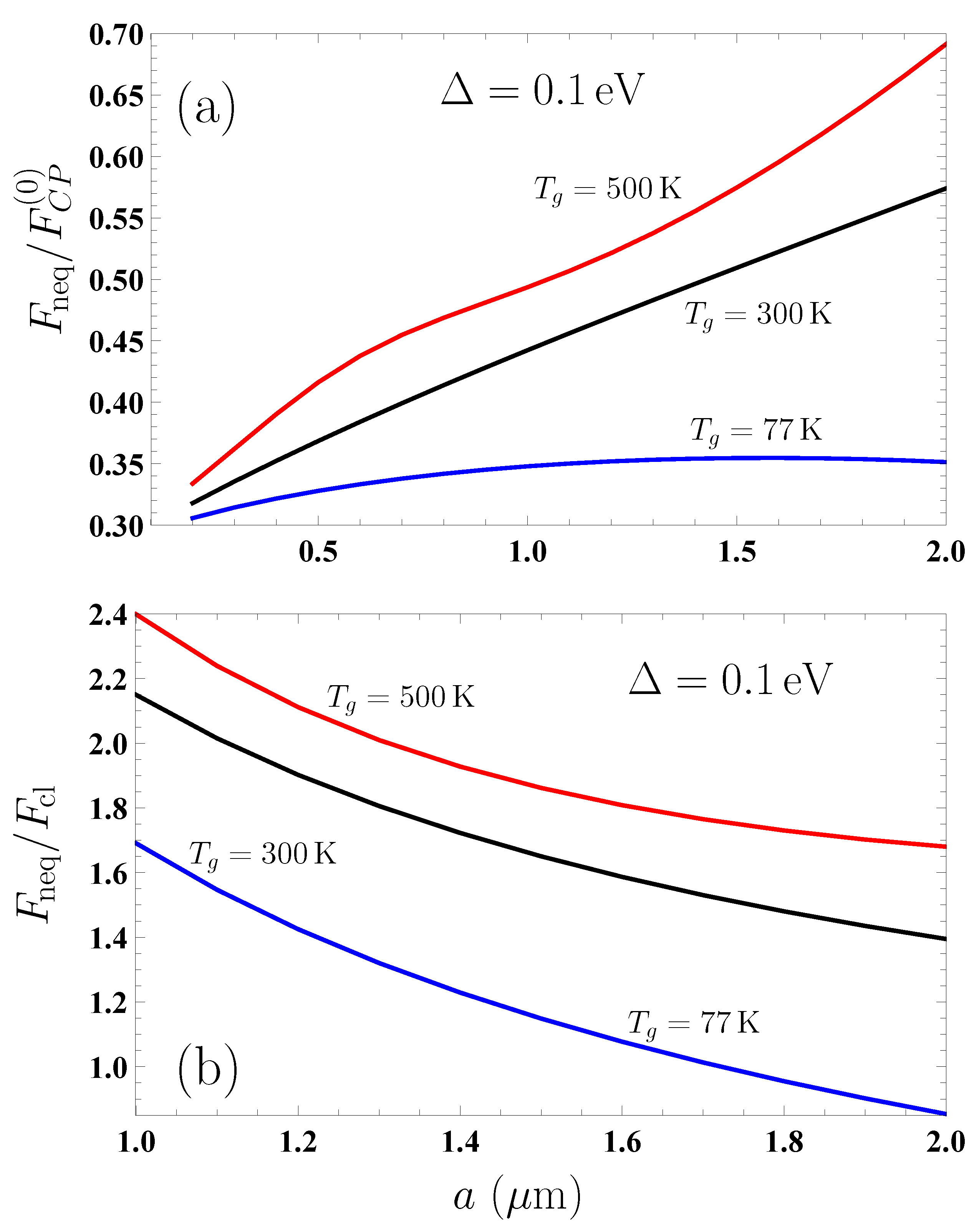
Now, we are in a position to present the computational results for the total nonequilibrium Casimir–Polder force F neq between a nanoparticle and a graphene-coated substrate, which is the sum of contributions F M given in Figure 4 and F r given in Figure 5. In Figure 6a,b and Figure 7a,b, the results for F neq are shown for the graphene coating with Δ = 0.1 and 0.2 eV, respectively. In each figure, the bottom, middle, and top lines are plotted for the graphene plate temperatures T g = 77 K, 300 K, and 500 K, respectively. In Figure 6a and Figure 7a, the values of F neq are normalized to the zero-temperature Casimir–Polder force F C P ( 0 ) from an ideal metal plane (32), whereas, in Figure 6b and Figure 7b, they are normalized to the classical limit of the Casimir–Polder force F cl from an ideal metal plane (34).
Thus, the middle lines in Figure 6a and Figure 7a reproduce the top and middle lines in Figure 2, respectively, which are also plotted for the equilibrium Casimir–Polder force from the graphene-coated substrate with Δ = 0.1 and 0.2 eV. Figure 6b and Figure 7b can be compared with Figures 1 and 2 in [50] and plotted there for a freestanding in vacuum graphene sheet in order to determine an impact of the SiO 2 substrate on the nonequilibrium force. By and large, Figure 6 and Figure 7 are in analogy to Figure 3 related to the case of an uncoated substrate.
From Figure 6 and Figure 7 it is seen that the nonequilibrium force F neq from the graphene-coated SiO 2 plate at both T g = 77 K and 500 K is larger in magnitude than the force F neq SiO 2 from an uncoated SiO 2 plate and from a freestanding graphene sheet. Thus, for a SiO 2 plate coated with a graphene sheet with Δ = 0.1 eV at T g = 77 K, the ratio F neq / F neq SiO 2 is equal to 1.05 and 0.94 at separations a = 0.2 and 2 μ m, respectively. The same ratio for the same graphene coating but at T g = 500 K is equal to 1.12 and 1.33 at the same respective separations. For a graphene coating with Δ = 0.2 eV at T g = 77 K the ratio F neq / F neq SiO 2 is equal to 1.04 and 1.01 at a = 0.2 and 2 μ m, and, if the graphene-coated plate is at the temperature T g = 500 K, it is equal to 1.04 and 1.32, respectively.
If we compare the Casimir–Polder force from the graphene-coated SiO 2 plate with that from a freestanding graphene sheet, F free , it is seen that the presence of a substrate significantly increases the magnitudes of both equilibrium and nonequilibrium forces. This increase is the most pronounced at short separations. As an example, for a graphene coating on a SiO 2 plate and a freestanding graphene sheet with Δ = 0.1 eV, we obtain F eq / F eq free = 4.3 and 1.4 at a = 0.2 and 2 μ m, respectively. For the nonequilibrium forces with the same value of Δ , the ratio F neq / F neq free is equal to 8.2 and 2.2 at T g = 77 K and to 4.7 and 1.6 at T g = 500 K at the same respective separations.
The above results allow to control the value of the nonequilibrium Casimir–Polder force acting on nanoparticles from the graphene-coated substrates.
5. Discussion

The out-of-thermal-equilibrium Casimir and Casimir–Polder forces present a rather novel subject that has been investigated only during the last 25 years. Despite this, considerable advances have already been made in understanding the underlying physics and mathematical description of the effects of nonequilibrium. Specifically, as noted in Section 1, the fundamental Lifshitz theory of the Casimir and Casimir–Polder forces was generalized for the out-of-thermal-equilibrium conditions [19,20,21,22,23,24,25]. At first, this was completed for the case when the material properties are temperature-independent, but in succeeding years it was generalized for materials whose response functions to the electromagnetic field explicitly depend on temperature as a parameter [29,30].
Graphene is a unique novel material whose response functions described by the polarization tensor essentially depend on the temperature. Because of this, the effects of nonequilibrium in the Casimir–Polder force acting on nanoparticles from a graphene sheet are best suited to both the theoretical study and practical utility in nanoelectronics. Previously, these effects were considered only for freestanding graphene sheets [49,50], which is a configuration not easily accessible in a laboratory. In this article, the nonequilibrium Casimir–Polder force on a nanoparticle from a substrate coated with gapped graphene sheet was investigated as the function of separation, temperature, and energy gap in the case of the most often used fused silica glass substrate. This opens a way to a practical implementation of this physical phenomenon in the field effect transistors and other devices of bioelectronics [62,63,64]. The obtained results can be also generalized to other two-dimensional materials and van der Waals heterostructures employing different 2D crystals [65,66,67].

6. Conclusions

To conclude, in this article the formalism of the Lifshitz theory generalized to out-of-thermal-equilibrium conditions with temperature-dependent material properties was used to investigate the nonequilibrium Casimir–Polder force between nanoparticles and either cooled or heated fused silica plate substrate coated with gapped graphene sheet. The response of graphene to the electromagnetic field was described by the polarization tensor in the framework of the Dirac model.
We investigated two different contributions to the nonequilibrium Casimir–Polder force and determined their physical meaning and relative role depending on the frequency and separation regions. The total nonequilibrium force from a graphene-coated fused silica glass substrate was compared with the equilibrium one from the same source, as well as with both equilibrium and nonequilibrium forces from an uncoated silica glass plate. A comparison with the nonequilibrium Casimir–Polder force from a freestanding in vacuum graphene sheet has also been performed.
It was shown that the nonequilibrium force from the graphene-coated silica glass substrate kept at both lower and higher temperature than in the environment is larger in magnitude than the nonequilibrium force from an uncoated silica glass plate and from a freestanding graphene sheet. According to the results obtained, an increase in the energy gap of graphene coating leads to smaller force magnitudes and to a lesser impact of the graphene coating on the nonequilibrium force acting on a nanoparticle on the source side of an uncoated silica glass plate. By and large, we determined the impact of temperature of a graphene sheet, the role of a substrate, and the role of the nonzero energy gap of graphene coating on the nonequilibrium Casimir–Polder force between a nanoparticle and a graphene-coated substrate spaced at different separations.
The above results may find application in the rapidly progressing areas of nanotechnology dealing with integrated nanoparticle–biomolecular systems.

Author Contributions

Conceptualization, G.L.K., V.M.M., and O.Y.T.; investigation, G.L.K., C.C.K., and V.M.M.; software, C.C.K.; writing—original draft, V.M.M.; writing—review and editing, G.L.K., C.C.K., and O.Y.T. All authors have read and agreed to the published version of the manuscript.

Funding

The work of O.Y.T. was supported by the Russian Science Foundation under Grant No. 21-72-20029. G.L.K. was partially funded by the Ministry of Science and Higher Education of Russian Federation (“The World-Class Research Center: Advanced Digital Technologies”, contract No. 075-15-2022-311 dated April 20, 2022). The research of V.M.M. was partially carried out in accordance with the Strategic Academic Leadership Program “Priority 2030” of the Kazan Federal University.

Institutional Review Board Statement

Not applicable.

Informed Consent Statement

Not applicable.

Data Availability Statement

Not applicable.

Conflicts of Interest

The authors declare no conflict of interest.

References

  1. Casimir, H.B.G.; Polder, D. The influence of retardation on the London-van der Waals forces. Phys. Rev. 1948, 73, 360–372. [Google Scholar] [CrossRef]
  2. Lifshitz, E.M. The theory of molecular attractive forces between solids. Zh. Eksp. Teor. Fiz. 1955, 29, 94–110, Translated Sov. Phys. JETP 1956, 2, 73–83. [Google Scholar]
  3. Derjaguin, V.B.; Dzyaloshinsky, I.E.; Koptelova, M.M.; Pitaevsky, L.P. Molecular-Surface Forces in Binary Solutions. Discuss. Faraday Soc. 1965, 40, 246–252. [Google Scholar] [CrossRef]
  4. Parsegian, V.A. Formulae for the electrodynamic interaction of point particles with a substrate. Mol. Phys. 1974, 27, 1503–1511. [Google Scholar] [CrossRef]
  5. Parsegian, V.A. Van der Waals Forces: A Handbook for Biologists, Chemists, Engineers, and Physicists; Cambridge University Press: Cambridge, UK, 2005. [Google Scholar]
  6. Buhmann, S.Y. Disperson Forces; Springer: Berlin, Germany, 2012; Volumes 1 and 2. [Google Scholar]
  7. Bordag, M.; Klimchitskaya, G.L.; Mohideen, U.; Mostepanenko, V.M. Advances in the Casimir Effect; Oxford University Press: Oxford, UK, 2015. [Google Scholar]
  8. Sernelius, B.E. Fundamentals of van der Waals and Casimir Interactions; Springer: New York, NY, USA, 2018. [Google Scholar]
  9. Lynch, I.; Dawson, K.A. Protein-nanoparticle interactions. Nanotoday 2008, 3, 40–47. [Google Scholar] [CrossRef]
  10. Moreno, F.; García-Cámara, B.; Saiz, J.M.; González, F. Interaction of nanoparticles with substrates: Effects on the dipolar behaviour of the particles. Opt. Express 2008, 16, 12487–12504. [Google Scholar] [CrossRef] [PubMed]
  11. Verma, A.; Stellacci, F. Effect of Surface Properties on Nanoparticle-Cell Interactions. Small 2010, 6, 12–21. [Google Scholar] [CrossRef] [PubMed]
  12. Saptarshi, S.R.; Duschl, A.; Lopata, A.L. Interaction of nanoparticles with proteins: Relation to bio-reactivity of the nanoparticle. J. Nanobiotech. 2013, 11, 26. [Google Scholar] [CrossRef]
  13. Kysylychyn, D.; Piatnytsia, V.; Lozovski, V. Electrodynamic interaction between a nanoparticle and the surface of a solid. Phys. Rev. E 2013, 88, 052403. [Google Scholar] [CrossRef]
  14. Sun, W. Interaction forces between a spherical nanoparticle and a flat surface. Phys. Chem. Chem. Phys. 2014, 16, 5846–5854. [Google Scholar] [CrossRef]
  15. Bimonte, G.; Emig, T.; Kardar, M. Casimir-Polder force between anisotropic nanoparticles and gently curved surfaces. Phys. Rev. D 2015, 92, 025028. [Google Scholar] [CrossRef]
  16. Wang, H.; Zhang, W.; Zeng, S.; Shen, C.; Jin, C.; Huang, Y. Interactions between nanoparticles and fractal surfaces. Water Res. 2019, 151, 296–309. [Google Scholar] [CrossRef] [PubMed]
  17. Andrén, D.; Länk, N.O.; Šípová-Jungová, H.; Jones, S.; Johansson, P.; Käll, M. Surface Interactions of Gold Nanoparticles Optically Trapped against an Interface. J. Phys. Chem. C 2019, 123, 16406–16414. [Google Scholar] [CrossRef]
  18. de Macedo, E.F.; Santos, N.S.; Nascimento, L.S.; Mathey, R.; Brenet, S.; de Moura, M.S.; Hou, Y.; Tada, D.B. Interaction between Nanoparticles, Membranes and Proteins: A Surface Plasmon Resonance Study. Int. J. Mol. Sci. 2023, 24, 591. [Google Scholar] [CrossRef] [PubMed]
  19. Dorofeyev, I.A. The force of attraction between two solids with different temperatures. J. Phys. A Math. Gen. 1998, 31, 4369–4380. [Google Scholar] [CrossRef]
  20. Henkel, C.; Joulain, K.; Mulet, J.P.; Greffet, J.J. Radiation forces on small particles in thermal near fields. J. Opt. A Pure Appl. Opt. 2002, 4, S109–S114. [Google Scholar] [CrossRef]
  21. Antezza, M.; Pitaevskii, L.P.; Stringari, S. New Asymptotic Behavior of the Surface-Atom Force out of Thermal Equilibrium. Phys. Rev. Lett. 2005, 95, 113202. [Google Scholar] [CrossRef] [PubMed]
  22. Antezza, M.; Pitaevskii, L.P.; Stringari, S.; Svetovoy, V.B. Casimir-Lifshitz force out of thermal equilibrium. Phys. Rev. A 2008, 77, 022901. [Google Scholar] [CrossRef]
  23. Bimonte, G. Scattering approach to Casimir forces and radiative heat transfer for nanostructured surfaces out of thermal equilibrium. Phys. Rev. A 2009, 80, 042102. [Google Scholar] [CrossRef]
  24. Messina, R.; Antezza, M. Scattering-matrix approach to Casimir-Lifshitz force and heat transfer out of thermal equilibrium between arbitrary bodies. Phys. Rev. A 2011, 84, 042102. [Google Scholar] [CrossRef]
  25. Bimonte, G.; Emig, T.; Krüger, M.; Kardar, M. Dilution and resonance-enhanced repulsion in nonequilibrium fluctuation forces. Phys. Rev. A 2011, 84, 042503. [Google Scholar] [CrossRef]
  26. Krüger, M.; Emig, T.; Bimonte, G.; Kardar, M. Non-equilibrium Casimir forces: Spheres and sphere-plate. Europhys. Lett. 2011, 95, 21002. [Google Scholar] [CrossRef]
  27. Krüger, M.; Bimonte, G.; Emig, T.; Kardar, M. Trace formulas for nonequilibrium Casimir interactions, heat radiation, and heat transfer for arbitrary bodies. Phys. Rev. B 2012, 86, 115423. [Google Scholar] [CrossRef]
  28. Klimchitskaya, G.L.; Mostepanenko, V.M.; Sedmik, R.I.P. Casimir pressure between metallic plates out of thermal equilibrium: Proposed test for the relaxation properties of free electrons. Phys. Rev. A 2019, 100, 022511. [Google Scholar] [CrossRef]
  29. Klimchitskaya, G.L.; Mostepanenko, V.M. Casimir-Polder Interaction of an Atom with a Cavity Wall Made of Phase-Change Material out of Thermal Equilibrium. Atoms 2020, 9, 4. [Google Scholar] [CrossRef]
  30. Ingold, G.-L.; Klimchitskaya, G.L.; Mostepanenko, V.M. Nonequilibrium effects in the Casimir force between two similar metallic plates kept at different temperatures. Phys. Rev. A 2020, 101, 032506. [Google Scholar] [CrossRef]
  31. Khandekar, C.; Buddhiraju, S.; Wilkinson, P.R.; Gimzewski, J.K.; Rodriguez, A.W.; Chase, C.; Fan, S. Nonequilibrium lateral force and torque by thermally excited nonreciprocal surface electromagnetic waves. Phys. Rev. B 2021, 104, 245433. [Google Scholar] [CrossRef]
  32. Castillo-López, S.G.; Esquivel-Sirvent, R.; Pirruccio, G.; Villarreal, C. Casimir forces out of thermal equilibrium near a superconducting transition. Sci. Rep. 2022, 12, 2905. [Google Scholar] [CrossRef]
  33. Obrecht, J.M.; Wild, R.J.; Antezza, M.; Pitaevskii, L.P.; Stringari, S.; Cornell, E.A. Measurement of the temperature dependence of the Casimir-Polder force. Phys. Rev. Lett. 2007, 98, 063201. [Google Scholar] [CrossRef]
  34. Aoki, H.; Dresselhaus, M.S. (Eds.) Physics of Graphene; Springer: Cham, Switzerland, 2014. [Google Scholar]
  35. Castro Neto, A.H.; Guinea, F.; Peres, N.M.R.; Novoselov, K.S.; Geim, A.K. The electronic properties of graphene. Rev. Mod. Phys. 2009, 81, 109–162. [Google Scholar] [CrossRef]
  36. Katsnelson, M.I. The Physics of Graphene; Cambridge University Press: Cambridge, UK, 2020. [Google Scholar]
  37. Klimchitskaya, G.L.; Mostepanenko, V.M.; Sernelius, B.E. Two approaches for describing the Casimir interaction with graphene: Density-density correlation function versus polarization tensor. Phys. Rev. B 2014, 89, 125407. [Google Scholar] [CrossRef]
  38. Klimchitskaya, G.L.; Mostepanenko, V.M. Quantum field theoretical framework for the electromagnetic response of graphene and dispersion relations with implications to the Casimir effect. Phys. Rev. D 2023, 107, 105007. [Google Scholar] [CrossRef]
  39. Bordag, M.; Fialkovsky, I.V.; Gitman, D.M.; Vassilevich, D.V. Casimir interaction between a perfect conductor and graphene described by the Dirac model. Phys. Rev. B 2009, 80, 245406. [Google Scholar] [CrossRef]
  40. Fialkovsky, I.V.; Marachevsky, V.N.; Vassilevich, D.V. Finite-temperature Casimir effect for graphene. Phys. Rev. B 2011, 84, 035446. [Google Scholar] [CrossRef]
  41. Bordag, M.; Klimchitskaya, G.L.; Mostepanenko, V.M.; Petrov, V.M. Quantum field theoretical description for the reflectivity of graphene. Phys. Rev. D 2015, 91, 045037, Erratum in Phys. Rev. D 2016, 93, 089907. [Google Scholar] [CrossRef]
  42. Bordag, M.; Fialkovskiy, I.; Vassilevich, D. Enhanced Casimir effect for doped graphene. Phys. Rev. B 2016, 93, 075414, Erratum in Phys. Rev. B 2017, 95, 119905. [Google Scholar] [CrossRef]
  43. Williams, G.; Kamat, P.V. Graphene-Semiconductor Nanocomposites: Excited-State Interactions between ZnO Nanoparticles and Graphene Oxide. Langmuir 2009, 25, 13869–13873. [Google Scholar] [CrossRef]
  44. Das, B.; Choudhury, B.; Gomathi, A.; Manna, A.K.; Pati, S.K.; Rao, C.N.R. Interaction of Inorganic Nanoparticles with Graphene. ChemPhysChem 2011, 12, 937–943. [Google Scholar] [CrossRef]
  45. Biehs, S.-A.; Agarwal, G.S. Anisotropy enhancement of the Casimir-Polder force between a nanoparticle and graphene. Phys. Rev. A 2015, 90, 042510, Erratum in Phys. Rev. A 2015, 91, 039901. [Google Scholar] [CrossRef]
  46. Devi, J.M. Simulation Studies on the Interaction of Graphene and Gold Nanoparticle. Int. J. Nanosci. 2018, 17, 1760043. [Google Scholar] [CrossRef]
  47. Low, S.; Shon, Y.-S. Molecular interactions between pre-formed metal nanoparticles and graphene families. Adv. Nano Res. 2018, 6, 357–375. [Google Scholar]
  48. Huang, L.-W.; Jeng, H.-T.; Su, W.-B.; Chang, C.-S. Indirect interactions of metal nanoparticles through graphene. Carbon 2021, 174, 132–137. [Google Scholar] [CrossRef]
  49. Klimchitskaya, G.L.; Mostepanenko, V.M.; Tsybin, O.Y. Casimir-Polder attraction and repulsion between nanoparticles and graphene in out-of-thermal-equilibrium conditions. Phys. Rev. B 2022, 105, 195430. [Google Scholar] [CrossRef]
  50. Klimchitskaya, G.L.; Korikov, C.C.; Mostepanenko, V.M.; Tsybin, O.Y. Impact of Mass-Gap on the Dispersion Interaction of Nanoparticles with Graphene out of Thermal Equilibrium. Appl. Sci. 2023, 13, 7511. [Google Scholar] [CrossRef]
  51. Klimchitskaya, G.L.; Mohideen, U.; Mostepanenko, V.M. Theory of the Casimir interaction from graphene-coated substrates using the polarization tensor and comparison with experiment. Phys. Rev. B 2014, 89, 115419. [Google Scholar] [CrossRef]
  52. Bordag, M.; Pirozhenko, I.G. Surface plasmon on graphene at finite T. Int. J. Mod. Phys. B 2016, 30, 1650120. [Google Scholar] [CrossRef]
  53. Hong, S.-Y.; Dadap, J.I.; Petrone, N.; Yeh, P.-C.; Hone, J.; Osgood, R.M., Jr. Optical Third-Harmonic Generation in Graphene. Phys. Rev. X 2013, 3, 021014. [Google Scholar]
  54. Li, H.; He, P.; Yu, J.; Lee, L.J.; Yi, A.Y. Localized rapid heating process for precision chalcogenide glass molding. Opt. Lasers Ingineer. 2015, 73, 62–68. [Google Scholar] [CrossRef]
  55. Marchena, M.; Song, Z.; Senaratne, W.; Li, C.; Liu, X.; Baker, D.; Ferrer, J.C.; Mazumder, P.; Soni, K.; Lee, R.; et al. Direct growth of 2D and 3D graphene nano-structures over large glass substrates by tuning a sacrificial Cu-template layer. 2D Materials 2017, 4, 025088. [Google Scholar] [CrossRef]
  56. Yuan, Y.; Wang, Y.; Liu, S.; Zhang, X.; Liu, X.; Sun, C.; Yuan, D.; Zhang, Y.; Cao, X. Direct chemical vapor deposition synthesis of graphene super-hydrophobic transparent glass. Vacuum 2022, 202, 111136. [Google Scholar] [CrossRef]
  57. Liu, M.; Zhang, Y.; Klimchitskaya, G.L.; Mostepanenko, V.M.; Mohideen, U. Demonstration of Unusual Thermal Effect in the Casimir Force from Graphene. Phys. Rev. Lett. 2021, 126, 206802. [Google Scholar] [CrossRef] [PubMed]
  58. Liu, M.; Zhang, Y.; Klimchitskaya, G.L.; Mostepanenko, V.M.; Mohideen, U. Experimental and theoretical investigation of the thermal effect in the Casimir interaction from graphene. Phys. Rev. B 2021, 104, 085436. [Google Scholar] [CrossRef]
  59. Henkel, C.; Klimchitskaya, G.L.; Mostepanenko, V.M. Influence of the chemical potential on the Casimir-Polder interaction between an atom and gapped graphene or a graphene-coated substrate. Phys. Rev. A 2018, 97, 032504. [Google Scholar] [CrossRef]
  60. Palik, E.D. (Ed.) Handbook of Optical Constants of Solids; Academic Press: New York, NY, USA, 1985. [Google Scholar]
  61. Zhu, T.; Antezza, M.; Wang, J.-S. Dynamical polarizability of graphene with spatial dispersion. Phys. Rev. B 2021, 103, 125421. [Google Scholar] [CrossRef]
  62. Donnelly, M.; Mao, D.; Park, J.; Xu, G. Graphene field-effect transistors: The road to bioelectronics. J. Phys. D: Appl. Phys. 2018, 51, 493001. [Google Scholar] [CrossRef]
  63. Puigpelat, E.; Ignés-Mullol, J.; Sagués, F.; Reigada, R. Interaction of Graphene Nanoparticles and Lipid Membranes Displaying Different Liquid Orderings: A Molecular Dynamics Study. Langmuir 2019, 35, 16661–16668. [Google Scholar] [CrossRef] [PubMed]
  64. Liu, H.; Hao, C.; Zhang, Y.; Yang, H.; Sun, R. The interaction of graphene oxide-silver nanoparticles with trypsin: Insights from adsorption behaviors, conformational structure and enzymatic activity investigations. Coll. Surf. B Biointerf. 2021, 202, 111688. [Google Scholar] [CrossRef] [PubMed]
  65. Mu, H.; Yu, W.; Yuan, J.; Lin, S.; Zhang, G. Interface and surface engineering of black phosphorus: A review for optoelectronic and photonic applications. Mater. Futur. 2022, 1, 012301. [Google Scholar] [CrossRef]
  66. Xu, R.; Guo, J.; Mi, S.; Wen, H.; Pang, F.; Ji, W.; Cheng, Z. Advanced atomic force microscopies and their applications in two-dimensional materials: A review. Mater. Futur. 2022, 1, 032302. [Google Scholar] [CrossRef]
  67. Zhuang, R.; Cai, S.; Mei, Z.; Liang, H.; Zhao, N.; Mu, H.; Yu, W.; Jiang, Y.; Yuan, J.; Lau, S.; et al. Solution-grown BiI/BiI3 van der Waals heterostructures for sensitive X-ray detection. Nat. Commun. 2023, 14, 1621. [Google Scholar] [CrossRef]
Figure 1. Optical data for the (a) real and (b) imaginary parts of the dielectric permittivity of fused silica glass are shown as the function of frequency along the real frequency axis.
Symmetry 15 01580 g001
Figure 2. The ratio of the equilibrium Casimir–Polder force acting on a nanoparticle from a plate at T p = T E = 300 K to that from an ideal metal plane at T p = T E = 0 is shown as the function of separation by the three lines plotted for a uncoated SiO 2 plate and coated by a graphene sheet with the energy gap Δ = 0.2 eV and 0.1 eV.
Symmetry 15 01580 g002
Figure 3. The ratio of the nonequilibrium Casimir–Polder force acting on a nanoparticle from a SiO 2 plate to the equilibrium one from an ideal metal plane (a) at T p = T E = 0 and (b) at T p = T E = 300 K (the classical limit) is shown as the function of separation. The bottom and top lines are for the plate temperatures T p = 77 K and 500 K, respectively. The middle lines demonstrate similar ratio when T p = T E = 300 K. In the inset, the region of short separations is shown on an enlarged scale.
Symmetry 15 01580 g003
Figure 4. The ratio of the first contribution to the nonequilibrium Casimir–Polder force acting on a nanoparticle from a SiO 2 plate coated by a graphene sheet with the energy gap (a) Δ = 0.1 eV and (b) Δ = 0.2 eV to the equilibrium one from an ideal metal plane at T p = T E = 0 is shown as the function of separation. The bottom and top lines are for the graphene plate temperatures T g = 77 K and 500 K, respectively. The middle lines demonstrate similar ratio where T g = T E = 300 K.
Symmetry 15 01580 g004
Figure 5. The ratio of the second contribution to the nonequilibrium Casimir–Polder force acting on a nanoparticle from a SiO 2 plate coated by a graphene sheet (a) at T g = 77 K and (b) T g = 500 K to the equilibrium one from an ideal metal plane at T p = T E = 0 is shown as the function of separation (a) by the two lines for Δ = 0.1 and 0.2 eV, where the latter coincides with that for an uncoated plate shown by the dashed line, and (b) by the two solid lines for Δ = 0.1 and 0.2 eV, where the latter coincides with that for an uncoated plate shown by the dashed one.
Symmetry 15 01580 g005
Figure 6. The ratio of the nonequilibrium Casimir–Polder force acting on a nanoparticle from a SiO 2 plate coated by a graphene sheet with Δ = 0.1 eV to the equilibrium one from an ideal metal plane (a) at T p = T E = 0 and (b) at T p = T E = 300 K (the classical limit) is shown as the function of separation. The bottom and top lines are for the graphene plate temperatures T g = 77 K and 500 K, respectively. The middle lines demonstrate similar ratio, where T g = T E = 300 K.
Symmetry 15 01580 g006
Figure 7. The ratio of the nonequilibrium Casimir–Polder force acting on a nanoparticle from a SiO 2 plate coated by a graphene sheet with Δ = 0.2 eV to the equilibrium one from an ideal metal plane (a) at T p = T E = 0 and (b) at T p = T E = 300 K (the classical limit) is shown as the function of separation. The bottom and top lines are for the graphene plate temperatures T g = 77 K and 500 K, respectively. The middle lines demonstrate similar ratio where T g = T E = 300 K. In the inset, the region of short separations is shown on an enlarged scale.
Symmetry 15 01580 g007
Disclaimer/Publisher’s Note: The statements, opinions and data contained in all publications are solely those of the individual author(s) and contributor(s) and not of MDPI and/or the editor(s). MDPI and/or the editor(s) disclaim responsibility for any injury to people or property resulting from any ideas, methods, instructions or products referred to in the content.