Article

Research on Eccentric Cavitation Bubble Collapse Dynamics within Droplets

1
Key Laboratory of Power Station Energy Transfer Conversion and System (Ministry of Education), School of Energy Power and Mechanical Engineering, North China Electric Power University, Beijing 102206, China
2
College of Mechanical and Transportation Engineering, China University of Petroleum-Beijing, Beijing 102249, China
3
Beijing Key Laboratory of Process Fluid Filtration and Separation, China University of Petroleum-Beijing, Beijing 102249, China
*
Authors to whom correspondence should be addressed.
Symmetry 2023, 15(7), 1375; https://doi.org/10.3390/sym15071375
Submission received: 29 May 2023 / Revised: 27 June 2023 / Accepted: 28 June 2023 / Published: 6 July 2023
(This article belongs to the Section Physics)

Abstract

:
The research on cavitation bubbles within droplets has gradually become one of the advanced topics in the field of confined fluid domains, which is closely related to the industry fields. However, the research on the relationship between cavitation bubbles collapsing within droplet and droplet splash dynamics is still in its infancy. Here, the high-speed photography experimental platform of cavitation bubbles within droplets was built to investigate the influences of the eccentricities of bubbles within droplets on the phenomenon. The concluding remarks are given as follows. (1) With the change in eccentricity, the droplet splash morphology can be divided into three cases: scattering, trident, and composite splashes respectively. Moreover, the movement trend of the bubble wall can be divided into three categories: spherical, fabiform, and ellipsoidal. (2) The height of the main peak of the droplet splash and the distribution law of the splash angle could be changed by the eccentricity. (3) The bubble collapse time of the droplet is significantly affected by the eccentricity.

1. Introduction

The process of bubble collapse is accompanied by a complex jet phenomenon, which is an important factor that causes damage to hydraulic machinery equipment. For example, cavitation in pumps, regulating valves, throttle orifices, and so on will lead to a decline in the operating conditions of the system, accompanied by noise, chattering, and other problems [1,2,3,4,5]. Furthermore, the research on drop splashes (caused by the cavitation) is of great significance to the operations of power plants [6,7,8,9,10]. The collapse process of bubbles in confined domains is affected by the boundary, resulting in a complex dynamics of bubble collapse [11]. Cavitation within the droplet will increase the degree of droplet atomization [12], causing violent droplet splash [13] and further explosions [14]. In addition, a cavitation bubble within a droplet is also of interest in many other fields [15,16,17,18], e.g., ultrasonic material cleaning [19] and inkjet printing [20]. Hence, cavitation bubbles within droplets has enormous benefits and broad research prospects.
The cavitation bubbles within droplets have been investigated by many researchers. Gonzalez and Ohl [21] conducted cavitation experiments in droplets in a sound field and found that there are three types of fragmentation after cavitation bubbles occurred within droplets: rapid atomization, laminar formation, and coarse fragmentation. Lindinger et al. [14] found that the phenomena of forward plume, backward plume, jet, and water film would occur after the droplet explodes. Marston and Thorodsen [22] found that during the process of bubble collapse within a droplet, a large number of fine jets are generated near the surface of the droplet, which were then decomposed into slightly splashed droplets. Zeng et al. [23] found that, after the bubble within a droplet collapses, it will form a fine jet, and the number of jets decreases with the increase of the viscosity. Guo et al. [24] proposed that the droplet splash morphology mainly includes four main types: transparent water layer, unstable coronal structure, stable coronal structure, and non-coronal structure.
In fact, the location of cavitation bubbles within droplets can greatly affect the dynamics of bubble collapse within droplets. In the cavitation experiment of a spherical droplet under a microgravity environment, Obereschkow [25] and Farhat [26] found that a bubble generated at the eccentric position of the droplet would cause the droplet to splash in two opposite directions. Kobel [27] and others studied the effect of the position of a bubble within a droplet under microgravity conditions on the generated spatter intensity and the surface disturbance of the droplet. They found that when the initial position of the bubble is close to the edge of the droplet, the droplet will break with the collapse of the bubble. Robert et al. [28] found that the eccentricity of the bubble generation position will affect the maximum speed of the bubble’s centroid movement. With the increase of the eccentricity, the amount of liquid ejected from the jet increased. Padilla-Martinez et al. [29] explored the evolution law of splashes after droplet cavitation through experiment and found that the angle of splash is related with the position of the bubble within the droplet. Thorodsen et al. [30] generated a bubble on a hemispherical droplet using a laser. When bubbles are generated at the top interface of the droplet, a small amount of liquid will be sprayed. Once the bubble generation position is gradually moved away from the top interface of the droplet, the coronal spray and jet are shown. Liu [31] conducted a droplet fragmentation experiment by reducing pressure to generate steam bubbles within a droplet. When bubbles collapse, a transverse jet would form inside the droplet. When the bubble is closer to the wall of the droplet, the spatter will be more intense and the deformation of the droplet will be greater.
Based on the literature, the influences of the bubble’s eccentric position on the collapsing dynamics and droplet splash have not been systematically investigated. In the present paper, the laser-induced eccentric bubbles within droplets will be employed for triggering the splash of droplets. Section 2 introduces the experimental system and parameters. Section 3 introduces and categorizes the dynamic process of bubble collapse. Section 4 analyzes the process of bubble collapse and quantitatively compares the outline of the bubble wall and the series of images of bubbles within a droplet. Section 5 shows the dynamic process of droplet splash and quantitatively analyzes the variation of the height and the angle of the main splash peak versus time. Section 6 analyzes the research on the collapse time of the cavitation bubble within the droplet. Section 7 concludes the main findings of the present paper.

2. Experimental System and Parameters

2.1. Experimental System

Figure 1 shows the experimental platform system for laser-induced eccentric cavitation bubbles within droplets. The whole platform includes four sub-systems: 1. Droplet preparation system; 2. Laser system; 3. High speed photography system; 4. Signal control system. Among them, the main equipment includes a Revealer X113 high-speed camera; Penny-100A-SC laser generator; Lande micro injection pump; DG535 digital delay signal generator; Lstouch-04 electric three-dimensional displacement table; lighting source; focusing lens; acrylic transparent pipeline; and computer. The specific operation processes of the experiment are as follows:
Step 1, start the laser generator and preheat for 5 min;
Step 2, inject water into the pipeline through a micro injection pump to form droplet of the same size;
Step 3, adjust the electric three-dimensional displacement table to ensure that the focusing lens is of the same height with the center of the droplet;
Step 4, adjust the position of the high-speed camera to ensure that the droplet is located in the center of the image, and set the camera speed;
Step 5, start the laser generator and ensure that the laser beam can focus at the eccentric position of the droplet through the focusing lens;
Step 6, coordinate the operation time of the laser generator and high-speed camera through a digital delay generator to ensure that the captured image is recorded correctly;
Step 7, capture the process of bubble collapse within droplet and droplet splash by a high-speed camera during the experiment;
Step 8, export the experimental results onto a computer using high-speed photography acquisition software for post-processing and analysis.

2.2. Parameters

Figure 2 shows the definition of experimental parameters. Among them, the X axis represents the coordinates of the horizontal direction, the Y axis represents the coordinates of the vertical direction. The arrows point out the positive direction of the axis. The yellow dot Od represents the center of the droplet, and the red dot Ob represents the initial position of the bubble. In addition, dbX is the distance between Od and Ob in the horizontal direction. ddX is the distance between the center of the droplet and the top of the droplet’s interface. Based on this, the eccentricity of cavitation bubble within the droplet in the horizontal direction is defined as follows:
ε X = d b X d d X

3. Classification of Splash Phenomenon

3.1. Case 1

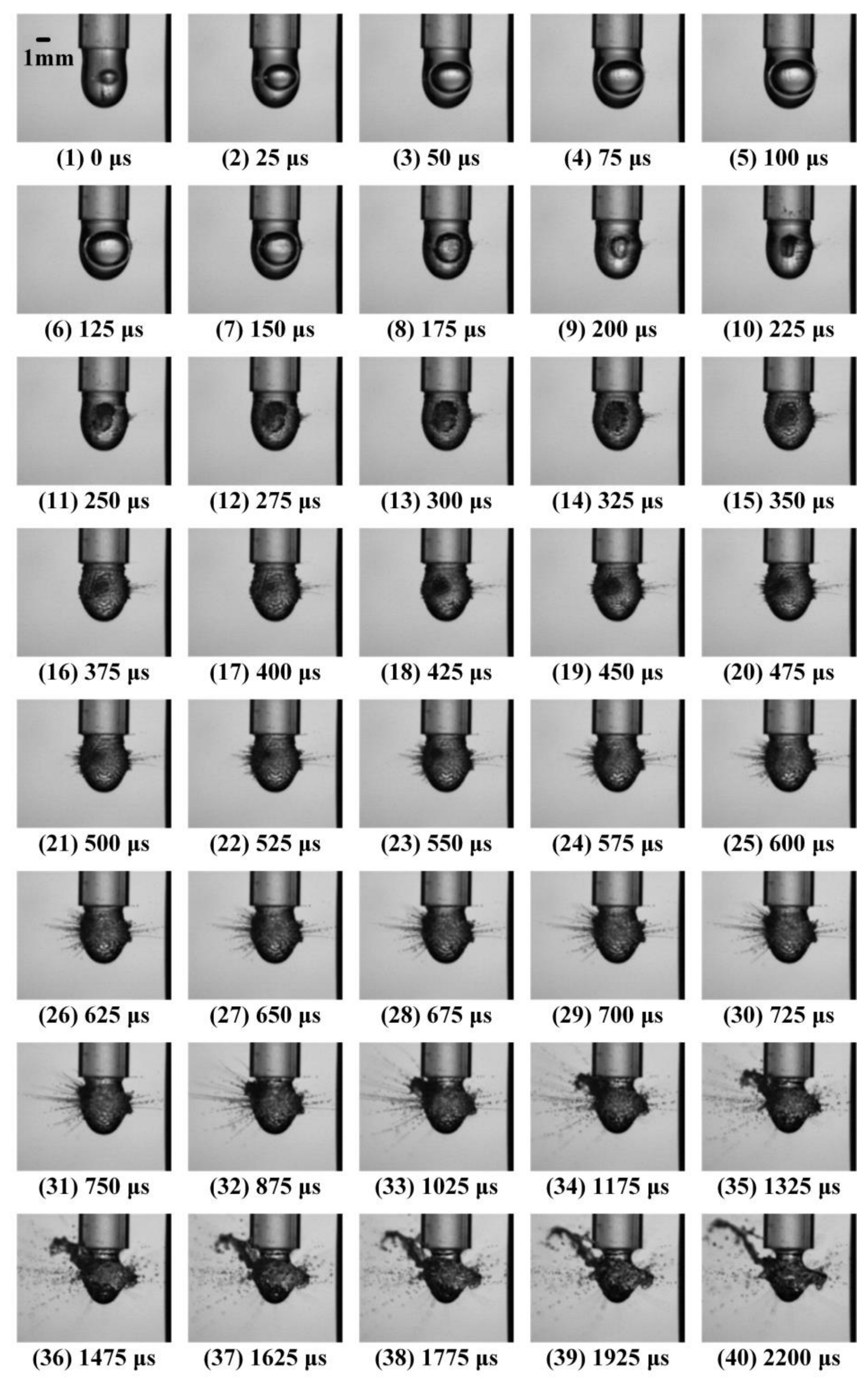
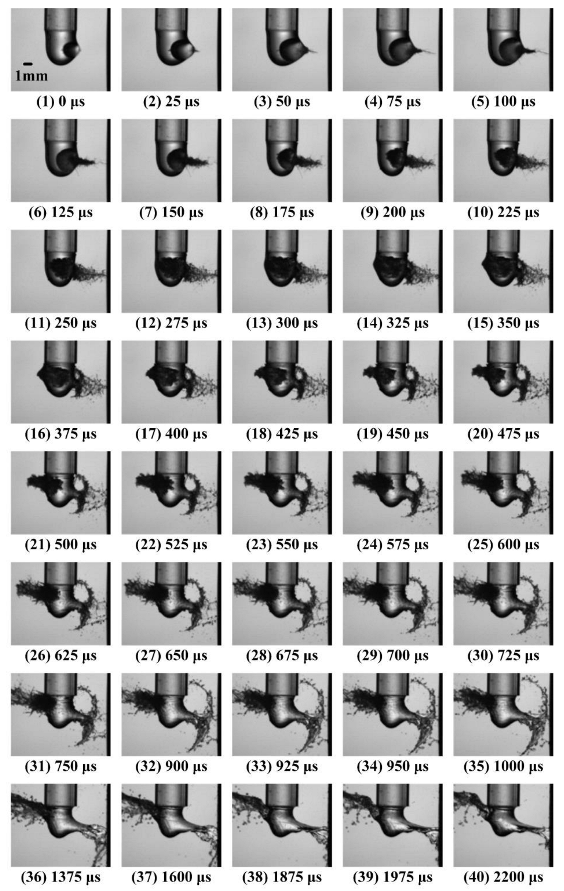
Figure 3 shows the collapse process of the bubble and the splash process of the droplet when εX = 0.17. As shown in Figure 3, scattered splash occurs on the surface of the droplet, the bubble shrinks into ellipsoids, and finally a triangular vapor cloud forms, which is defined as case 1.
In Figure 3, subfigures 1–5 show the growth processes of the bubble, during which the bubble volume reaches its maximum, and the right side of the droplet is slightly expanding. Subfigures 6–9 show the first collapse process of the bubble, within which the bubble shrinks into a non-spherical shape and finally an ellipsoidal shape. The surface on the right side of the droplet shows slight splash in the horizontal direction. Subfigures 10–17 show the second collapse process of the bubble, which evolves into a vapor cloud moving to the left. A rapidly developing splash is formed at the right side of the droplet. Subfigures 18–24 show the third collapse process of the bubble, with the volume of the vapor cloud gradually decreasing and multiple scattering splashes appearing on both sides. Subfigure 18 shows the beginning of the formation of the triangular vapor cloud. Subfigures 25–40 show the later stage of the bubble collapse, where the vapor cloud collapses multiple times before annihilation, and the surface of the droplet continues to oscillate. Among them, the scattered splash on the left side of the droplet in subfigures 33–40 gradually evolves into a single strand splash with a strong trend, resulting in the severe surface deformation of the droplet.

3.2. Case 2

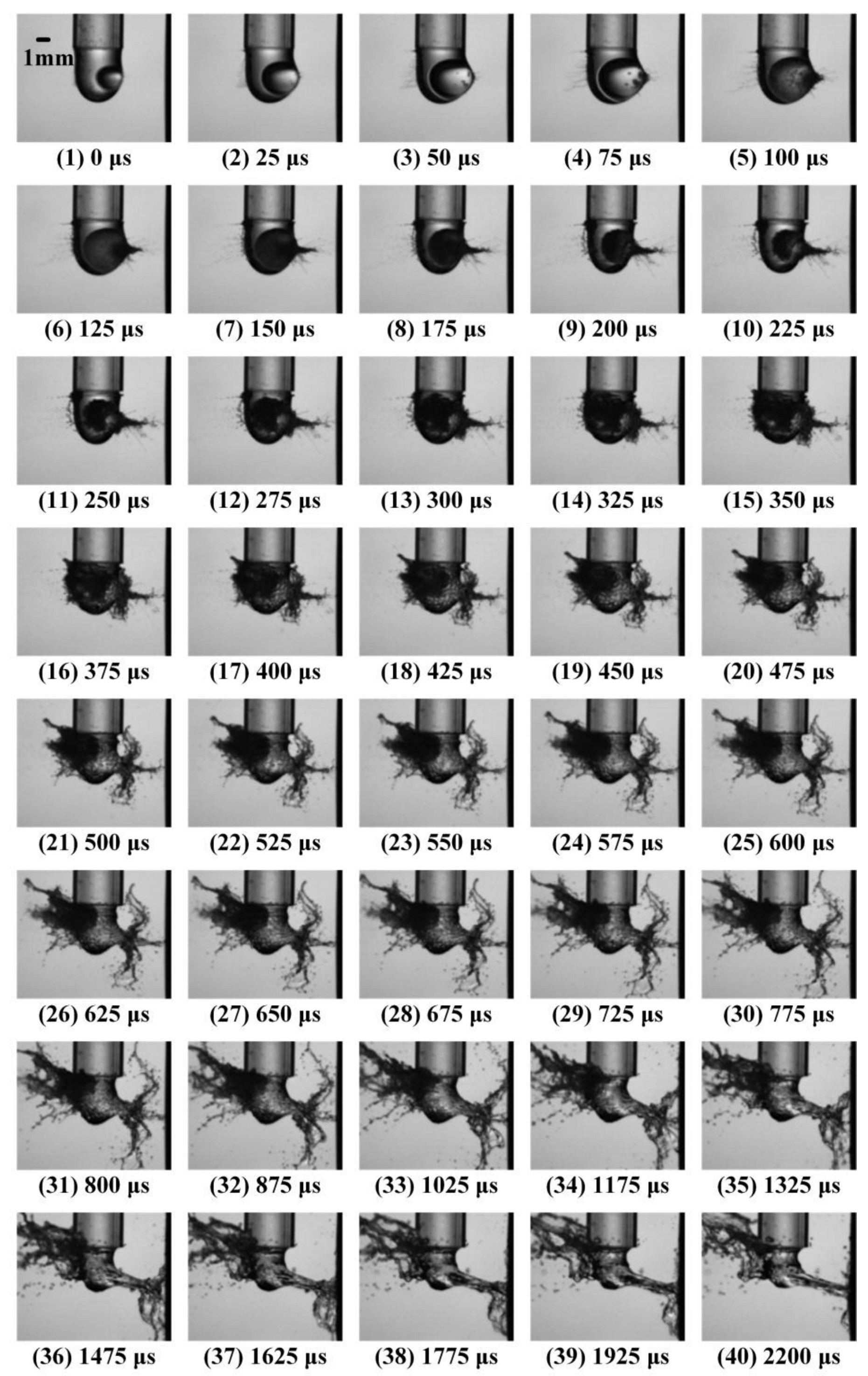
Figure 4 shows the collapse process of the bubble and the splash process of the droplet when εX = 0.50. Obvious trident splash occurs on the surface of the droplet, the bubble shrinks into a fabiform, and finally an irregular vapor cloud is formed. In the later stage of collapse, the significant deformation occurs in the droplet, which is defined as case 2.
In Figure 4, subfigures 1–5 show the growth processes of the bubble. The bubble volume reaches its maximum, and the right side of the droplet is significantly affected by the bubble, resulting in protrusions. A weak splash appears on the left side of the droplet. Subfigures 6–10 show the first collapse process of the bubble, in which it shrinks in a non-spherical manner and finally shrinks into a fabiform depression towards the left. A root shape splash appears on the right side of the droplet, while a weak scattered splash appears on the left side. Subfigures 11–15 show the second collapse process of the bubble, which evolves into a vapor cloud moving to the left. The left side of the droplet is affected by the movement of the vapor cloud, resulting in a violent splash. Subfigures 16–40 show the later collapse stage of bubble, where the left surface of the droplet impacts the vapor cloud, resulting in a sharp development of a trident-shaped splash on the left side of the droplet and the droplet surface continues to oscillate. Among them, in subfigures 16–35, the splash on the right side of the droplet evolves into a distinct trident splash. In subfigures 36–40, the splash on the right side of the droplet develops into a sharp peak shape, and the droplet significantly shrinks.

3.3. Case 3

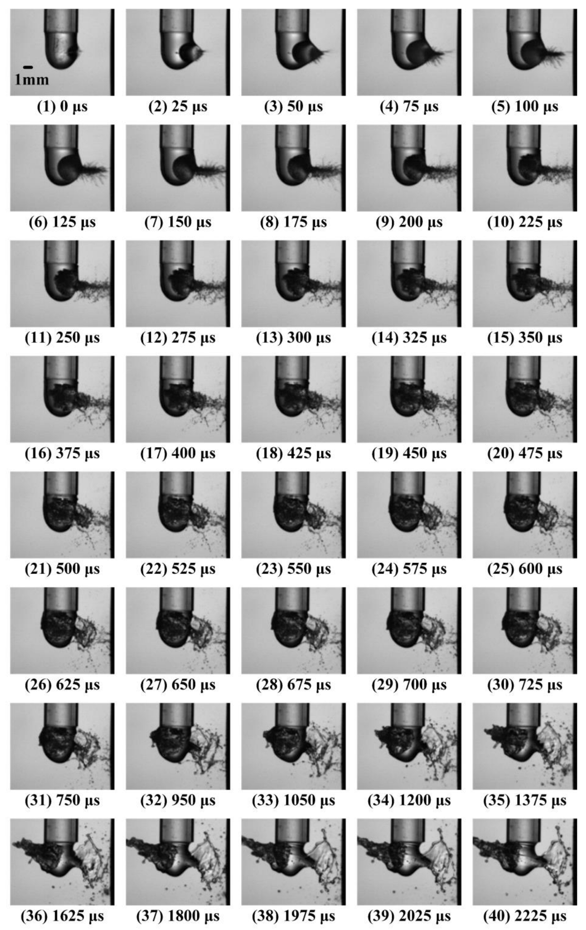
Figure 5 shows the collapse process of the bubble and splash process of the droplet when εX = 0.99 (corresponding to the case 3). A horn splash occurs on the surface of the droplet on the right side and a conical splash occurs on the left side of the droplet. The bubble shrinks into a conical shape, and finally forms a triangular vapor cloud. In the later collapse stage, there is significant deformation at the connection between the right side of the droplet and the pipeline.
In Figure 5, subfigures 1–5 show the growth processes of the bubble. In subfigure 5, the bubble volume reaches its maximum, and the right side of the droplet is significantly affected by the bubble, resulting in a protrusion. There is no obvious phenomenon on the left side of the droplet. Subfigures 6–11 show the first collapse process of the bubble, during which the bubble shrinks in a non-spherical shape and finally shrinks into a conical shape. Affected by the collapse of the bubble, the splash shows a significant root shape on the right side. Subfigures 12–20 show the second collapse process of the bubble, which evolves into a vapor cloud moving to the left. The root shape splash on the right side of the droplet develops violently, and the splash range gradually expands. Subfigures 21–40 show the later stage of the bubble collapse, where the vapor cloud collapses multiple times and then annihilates. In subfigure 24, the splash on the right side of the droplet begins to evolve into a horn splash. In subfigures 32–40, the left side of the droplet is impacted by a vapor cloud, forming a rapidly developing conical splash. The right side of the droplet has a horn-shaped splash that evolves into a water film, and there is significant deformation at the connection between the right side of the droplet and the pipeline.

3.4. Transition between Case 1 and Case 2

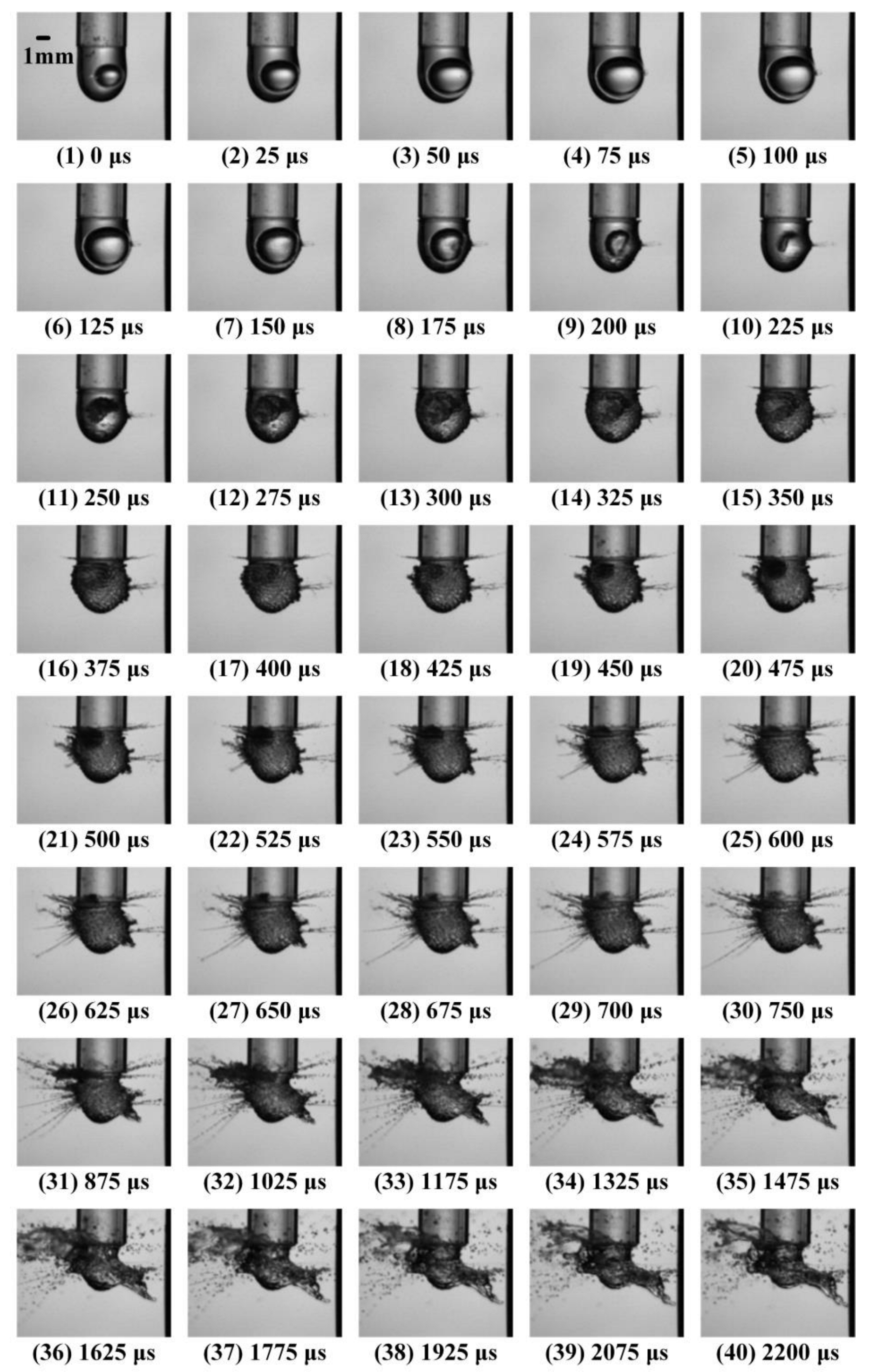
In addition to the three typical droplet splash cases, there are some atypical droplet splash transition cases in the process of adjusting the eccentricity. Figure 6 shows the processes of bubble collapse and droplet splash when εX = 0.33.
In Figure 6, subfigures 1–5 show the stage of bubble growth, and the bubble volume reaches its maximum in subfigure 5. Deformation occurs in the right side of the droplet due to the influence of bubble growth, while the left side shows no significant change. Subfigures 6–10 show the first collapse process of the bubble, which rapidly collapses in the later stage and shrinks into a long strip shape. A single splash appears on the right side of the droplet due to the collapse of the bubble. Subfigures 11–18 show the second collapse process of the bubble, where the bubble forms a vapor cloud that moves to the left, and the droplet oscillates and pits appear on the surface. Subfigures 19–24 show the third collapse process of the bubble, where deformation occurs in the right side of the droplet and it begins to experience double splash. The left side of the droplet is impacted by a vapor jet, resulting in a scattered splash. Subfigures 25–40 show the later stage of bubble collapse, where the vapor cloud collapses multiple times and then annihilates. In subfigures 31–40, the deformation on the right side of the droplet is significant, resulting in the formation of double splatters. The left side of the droplet exhibits an intense scattered splash.

3.5. Transition between Case 2 and Case 3

Figure 7 shows the processes of bubble collapse and splash of droplet at εX = 0.83, which is a demonstrating transition case between cases 2 and 3.
In Figure 7, subfigures 1–5 show the processes of bubble growth, with the bubble volume reaching its maximum in subfigure 5. The right side of the droplet is significantly affected by the cavitation, and there is no obvious protrusion on the left side of the droplet. Subfigures 6–10 show the first collapse process of the bubble, which collapses in a non-spherical shape and eventually shrinks into a triangle. Affected by the collapse of the bubble, the droplet forms a significant root shape splash on the right side. Subfigures 11–19 show the second collapse process of the bubble, which evolves into a triangular vapor cloud moving towards the left. The root shape splash on the right side of the droplet is expanded, and the splash gradually evolves into a trumpet shape. In subfigures 16–20, the left side of the droplet is impacted by the jet and begins to exhibit a root shape splash. Subfigures 20–40 show the later collapse stage. The splash range on the right side of the droplet is further expanded, forming a horn splash pattern, while the root shape splash on the left side of the droplet develops violently, and severe deformation occurs on the surface of the droplet.

4. Collapse Dynamics of Cavitation Bubble

4.1. Outline of Bubble Wall

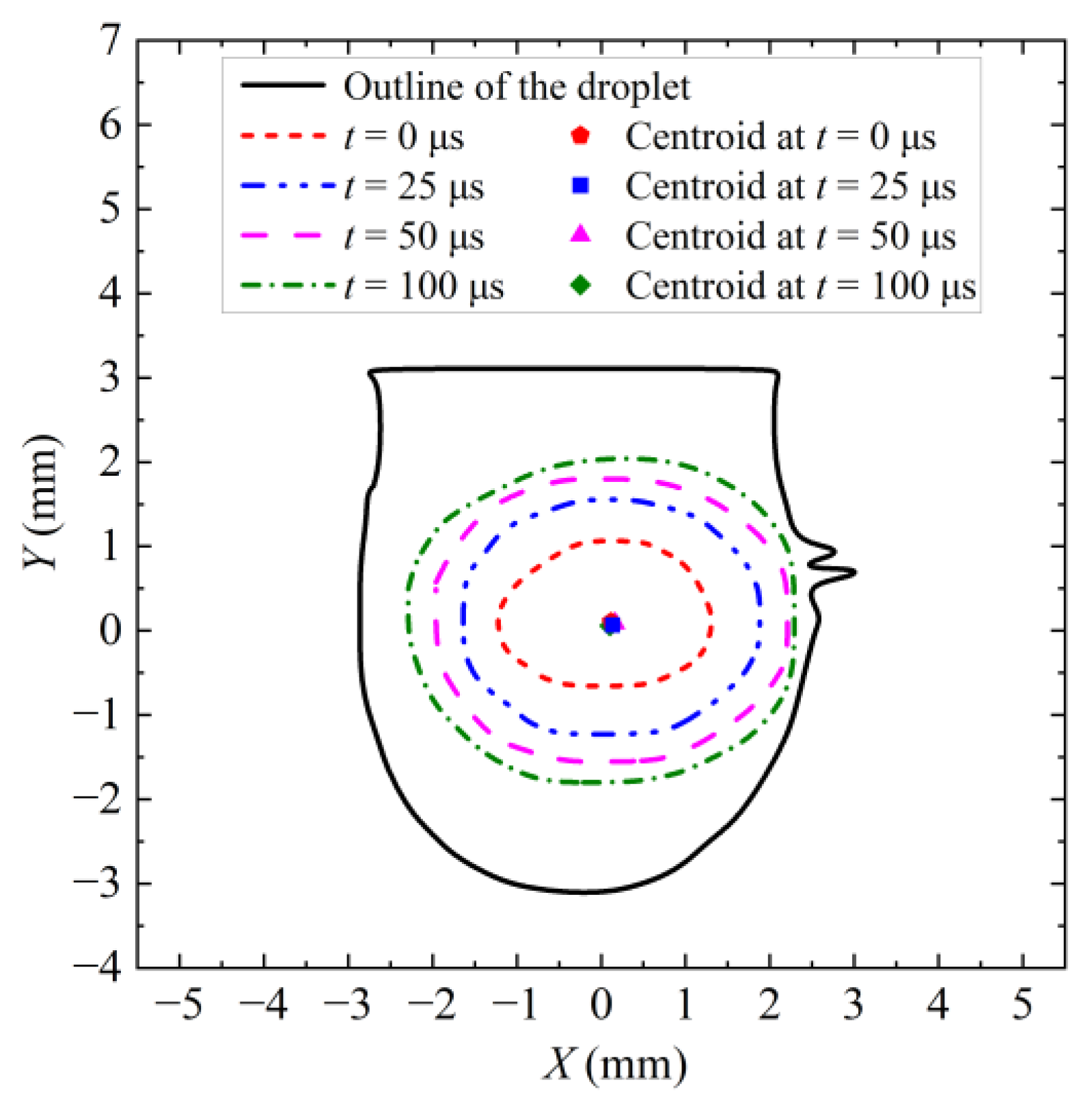
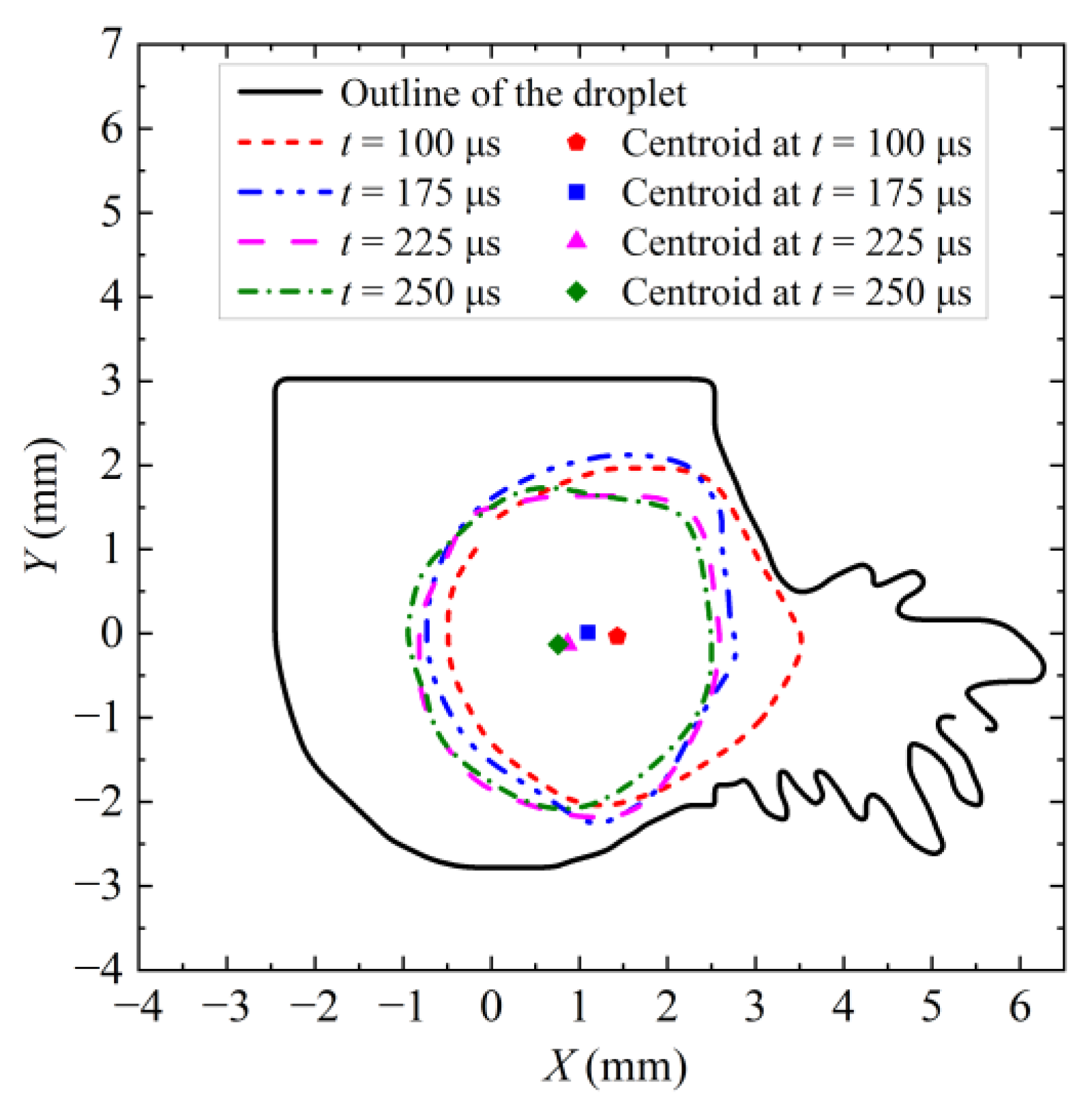
Figure 8 shows the outline of the growth processes of the bubbles for case 1 at different times. The geometric length of the bubble is represented by the abscissa and ordinate. The outline of the droplet at the maximum volume of the bubble is represented by the black solid line and the red, blue double, magenta, and green dashes represent the outline of the bubble wall at 0 μs, 25 μs, 50 μs, and 100 μs, respectively. When t = 100 μs, the outline of the bubble wall reaches the maximum. The red pentagon, blue rectangle, magenta triangle, and green diamond in the figures represent the centroid position of the bubble at the given time, respectively. In the following, the content and setting of the outline figures are consistent.
In the growth process of the bubble, the bubble wall basically keeps its ellipsoidal shape. The growth speed of the bubble in all directions basically stays the same. Due to the initial position of the bubble is off the right, a weak splash occurs on the right side of the droplet. In addition, the centroid position of the bubble remains basically unchanged during the growth process of bubble.
Figure 9 shows the outline of the first collapse of the bubble for case 1 at different times. When t = 100 μs, the outline of the bubble wall reaches its maximum. At the first stage, the bubble wall is basically shrunk into a spherical shape. The shrinkage speed of the bubble wall gradually accelerates. In addition, during the initial stage of the collapse, the centroid position of the bubble gradually moves towards the upper left.
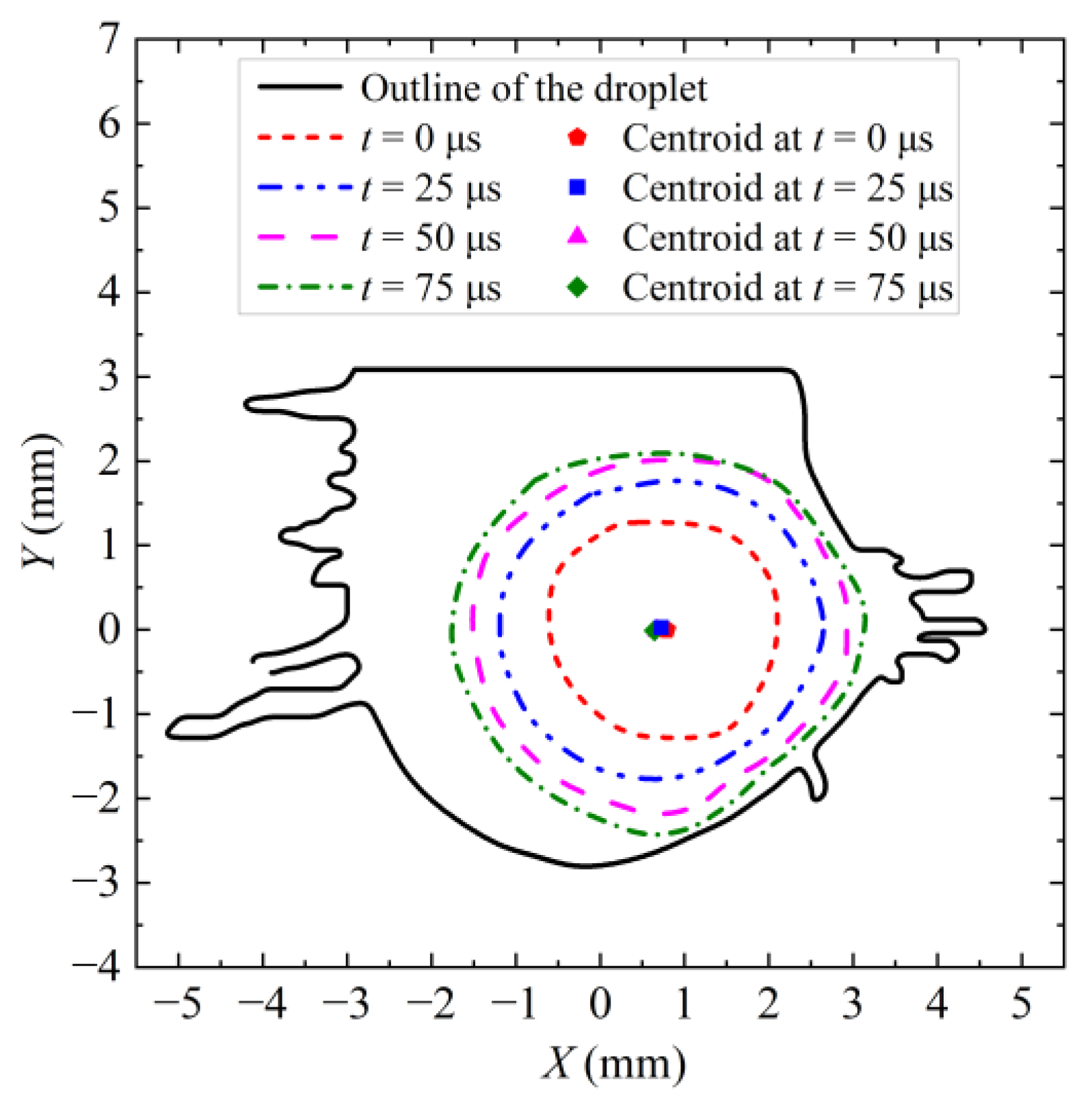
Figure 10 shows the outline of the growth processes of the bubbles for the case 2 at different times. When t = 75 μs, the outline of the bubble wall reaches its maximum. In this case, the droplet outline slightly deforms as bubble expands toward both ends. When the bubble volume reaching its maximum, the droplet causes scattered splash on both sides. In addition, the centroid position of bubble remains.
Figure 11 shows the outline of the first collapse process of the bubble for the case 2 at different times. When t = 75 μs, the bubble is maximum. Between 75 μs and 175 μs, the shrinkage of the bubble wall basically remains spherical. Between 175 μs and 225 μs, non-spherical deformation occurs in the bubble. The right surface of the bubble wall is affected by droplet pressure and the depression occurs, transforming bubble into a fabiform shape. In this case, the shrinkage of the bubble wall near the droplet surface is much greater than the bubble wall far away from the droplet surface. The shrinkage speed of the bubble wall gradually accelerates. During the collapse process of the bubble, the centroid position of the bubble moves upperleft.
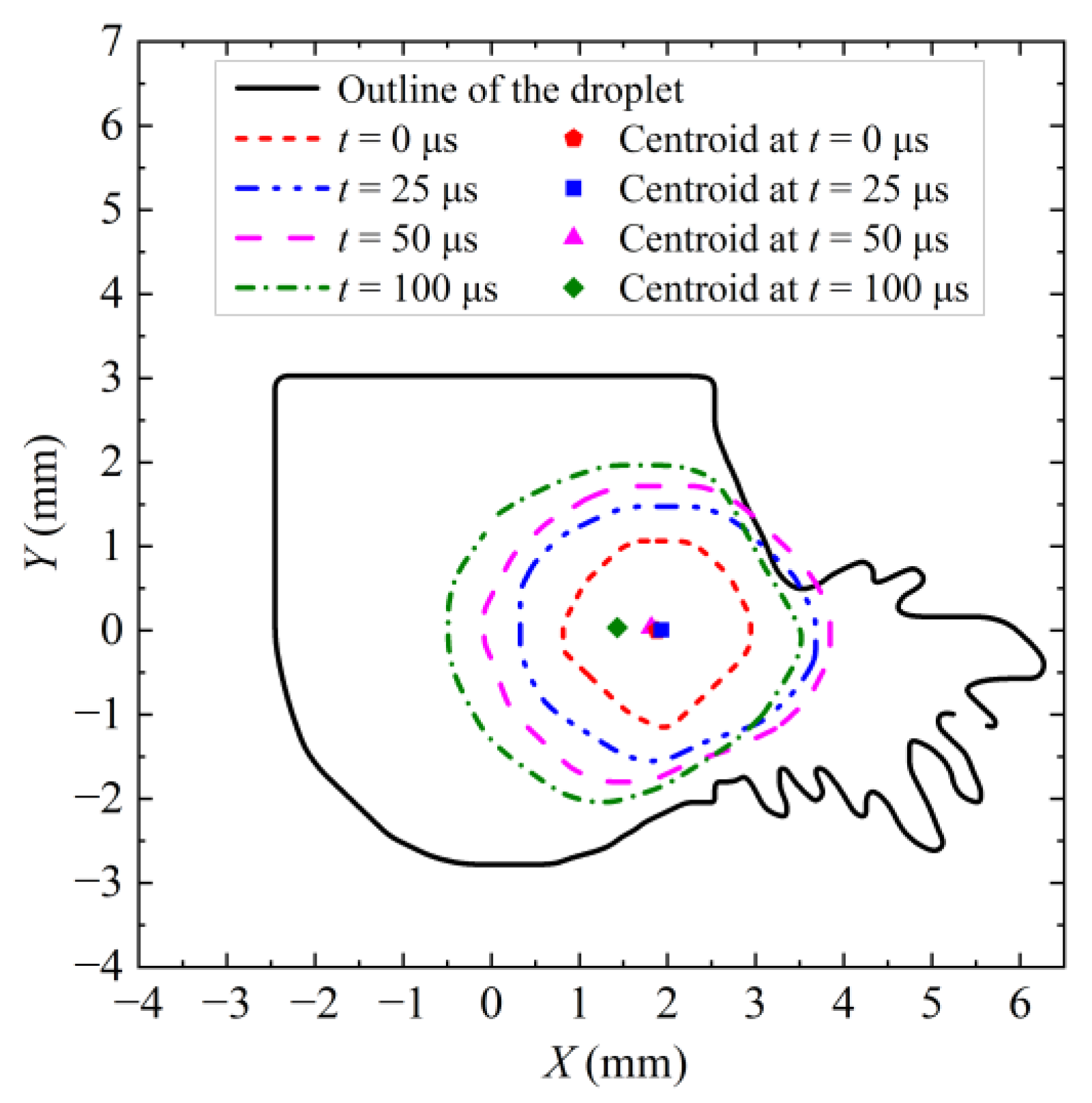
Figure 12 shows the outline of the growth processes of the bubbles for the case 3 at different times. When t = 100 μs, the bubble reaches its maximum. In the growth process of the bubble, the left end of the bubble wall maintains spherical growth, while the right end maintains elliptical change. The right end of the bubble expands to the right and shrinks to the left. When it grows to a certain extent, the bubble is squeezed and contracted by the droplet. In this case, the outline of the droplet is affected by the bubble and expands to the right. When the outline of bubble wall reaches the maximum, root shape splash occurs on the right side of the droplet. In addition, during the process of bubble growth, the right wall shrinks to the left in the later growth stage. The centroid of the bubble remains unchanged at first, and then rapidly moves to the left.
Figure 13 shows the outline of the first collapse processes of the bubbles for the case 3 at different times. When t = 100 μs, the outline of the bubble wall reaches the maximum. During the first collapse stage of bubble, the shrinkage of the bubble wall basically stays ellipsoidal. In this case, the shrinkage of the right end of the bubble wall is much greater than that of the left end. During the first collapse, the centroid of the bubble is moving leftward.

4.2. Image of Bubble and Droplet Boundaries

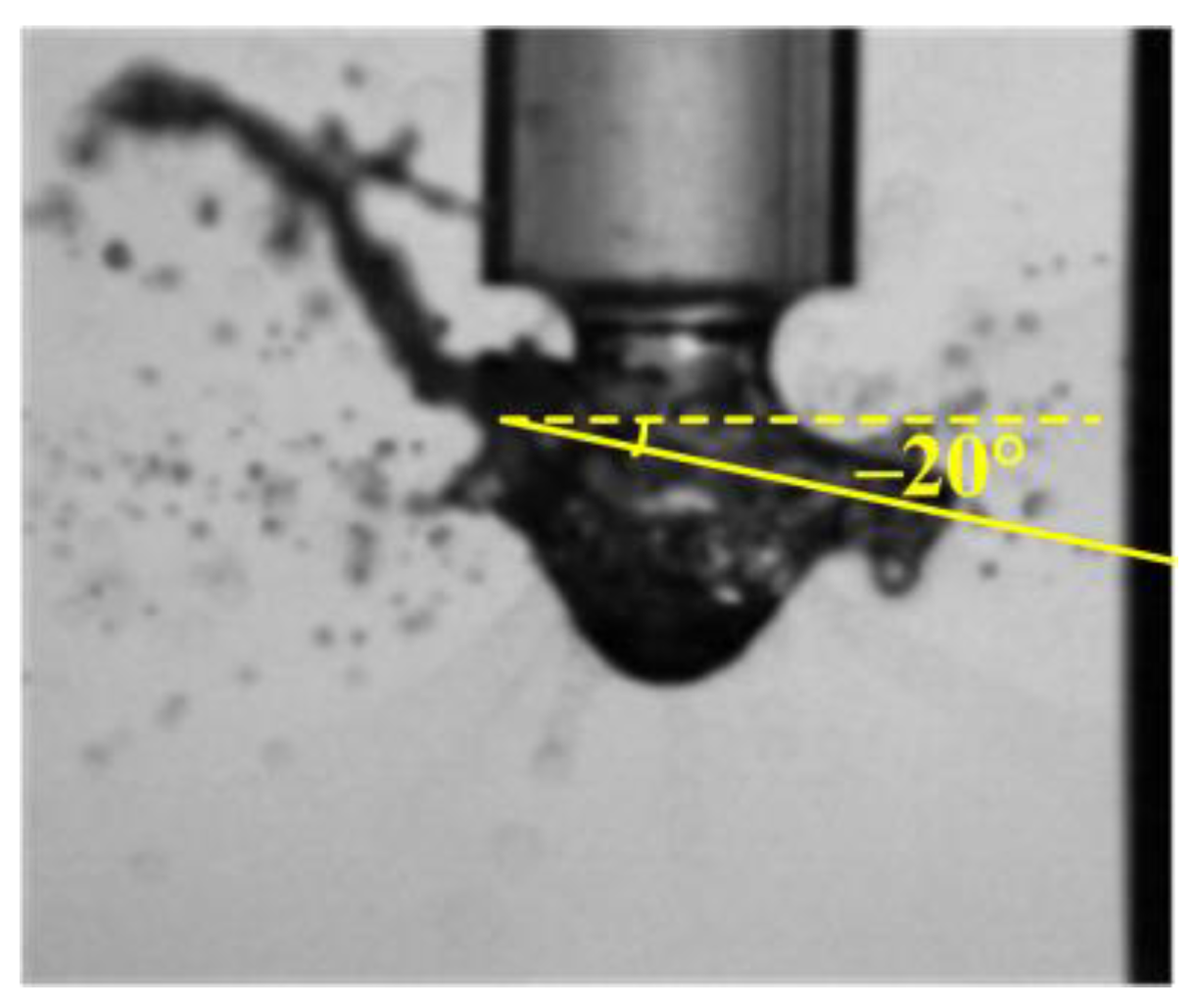
Figure 14 shows the angle of the main peak of droplet splash for the case 1. The horizontal direction is represented by the yellow dashed lines in the figure, and the direction of the main peak of droplet splash is represented by the yellow solid line, and the angle of the main peak of the splash of the droplet is represented by the angle between the two lines (with anti-clockwise defined as the positive direction). For example, the angle of the main peak of droplet splash in Figure 14 is −20°.
Figure 15 shows the images of the boundaries of the bubble and the droplet in the −20° direction for the case 1. The image is cut equidistantly, and then they are merged into a single picture. The length is represented by the horizontal axis, and the time is represented by the vertical axis. The bubble boundary, droplet boundary, and the main peak of the splash of the droplet are shown by the arrows in Figure 15. It can be seen that the splash occurs on both sides of the droplet and the bending occurs in the droplet.
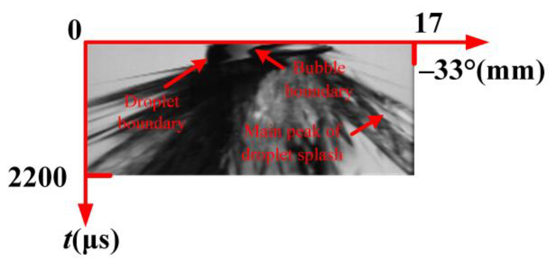
Figure 16 shows the angle of the main peak of droplet splash for the case 2 with the angle −33°.
Figure 17 shows the images of the boundaries of the bubble and the droplet with angle −33°. As can be seen, the splashes on both sides of the droplet are obvious. In the early stage of bubble collapse, deformation occurs in the right side of the droplet due to the influence of bubble growth and collapse, as shown in box (1). As the bubble collapses, severe splash occurs on the right side of the droplet shown in the box (2). Within box (3)‒(5), the vapor cloud continues to move to the left, splash occurs on the left side of droplet, and the surface of the droplet oscillates together with etch pits.
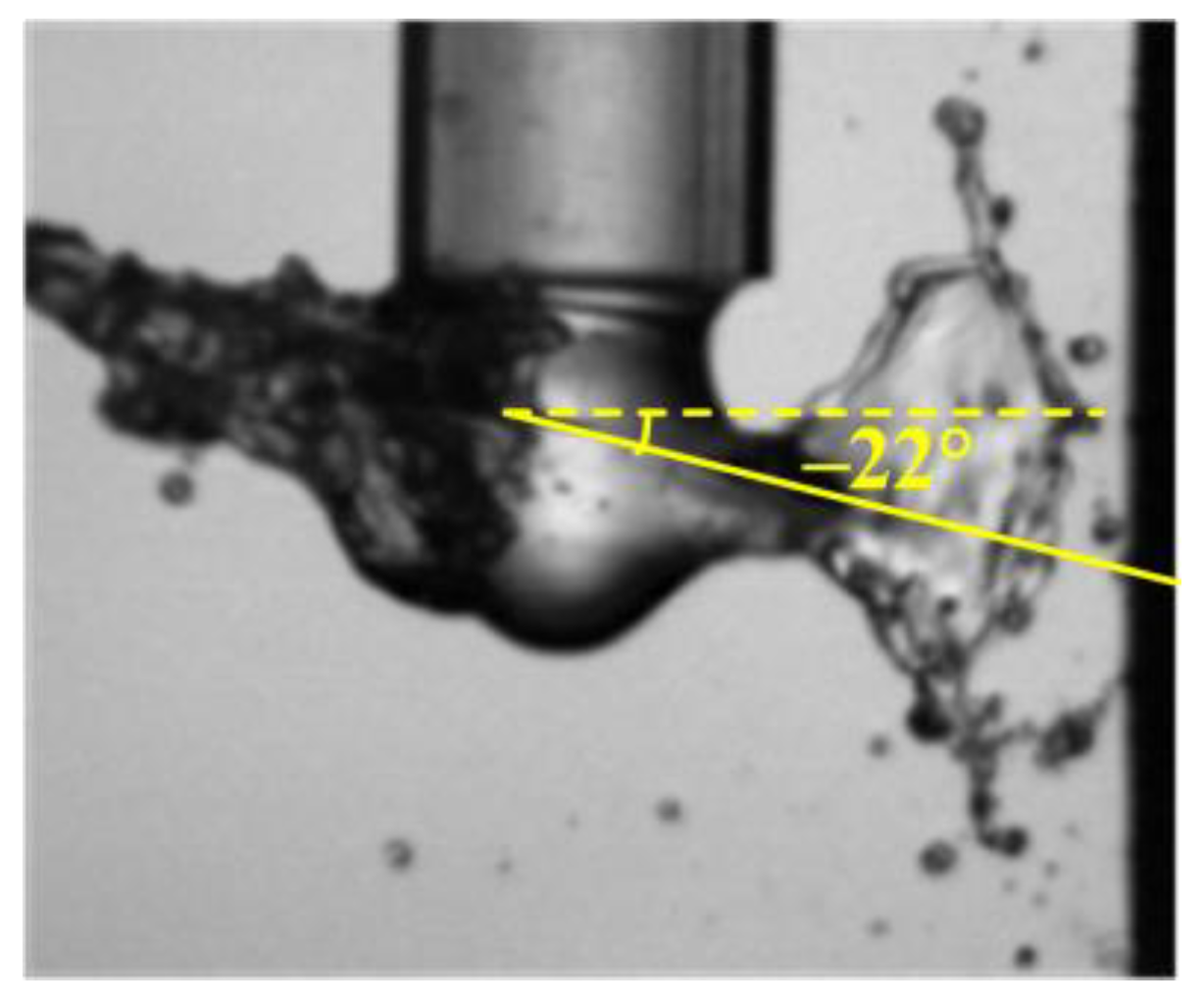
Figure 18 shows the angle of the main peak of droplet splash for the case 3 with angle −22°.
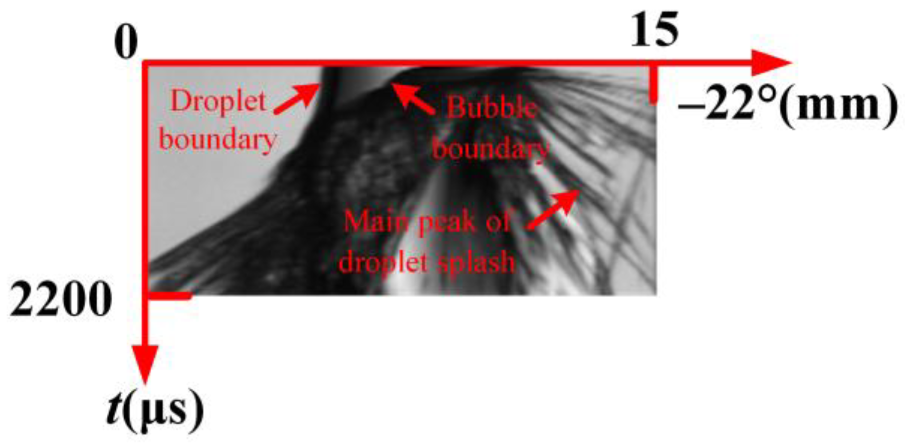
Figure 19 shows the composite image of the boundaries of the bubble and the droplet with angle −22° for the case 3. It can be seen that splashes occur at both sides of the droplet. At the early stage of bubble collapse, a violent splash occurs at the right side of the droplet.

5. Splash Dynamic of Droplet

5.1. Height of Main Peak

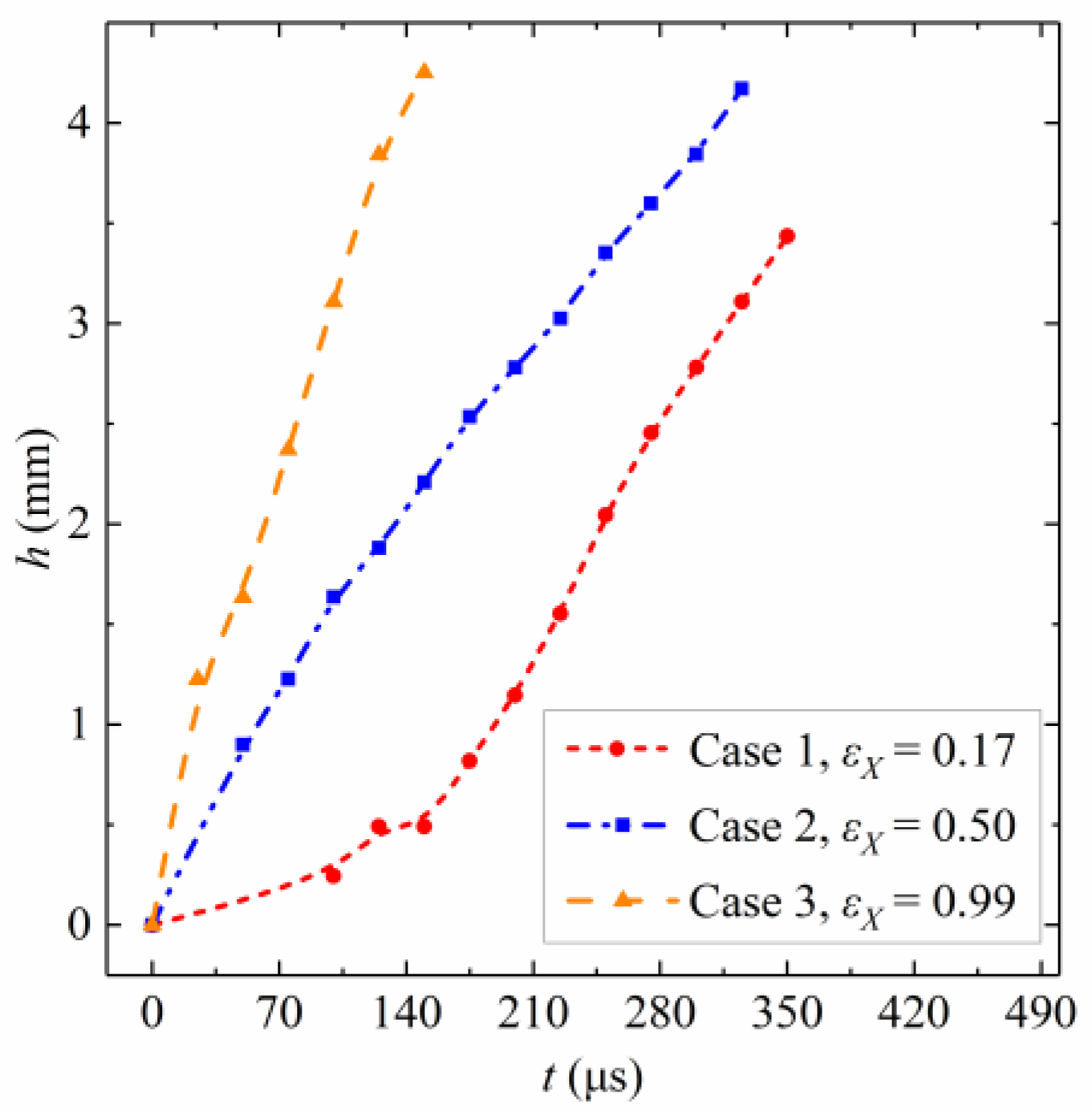
Figure 20 shows the variation of the height of the main peak of droplet splash with time. Among them, time t is represented by the horizontal axis, and the height of the splash of the droplet h is represented by the vertical axis. The red dash, blue double dot, and yellow dash represent the temporal variation of the main peak of the splash of the droplet in the horizontal typical cases 1-3, respectively.
In Figure 20, the height of the main peak of droplet splash shows a significant upward trend. In case 1, the growth rate of the main peak height curve shows a turning point around 100μs. Afterwards, the growth rate of the height of the main peak begins to accelerate, with the highest height of the main peak being 3.4 mm. Based on the wall contour of the first collapse of the bubble in case 1 (in Section 4.1), it can be seen that when t = 100 μs, the first collapse of the bubble begins. In this case, the collapse processes of the bubble will have a synergistic effect on the splash of the droplet.
In cases 2 and 3, the slope of the curve for the height of the main peak of droplet splash remains basically unchanged, with the highest main peak of the splash being 4.2–4.3 mm.

5.2. Angle of Splash

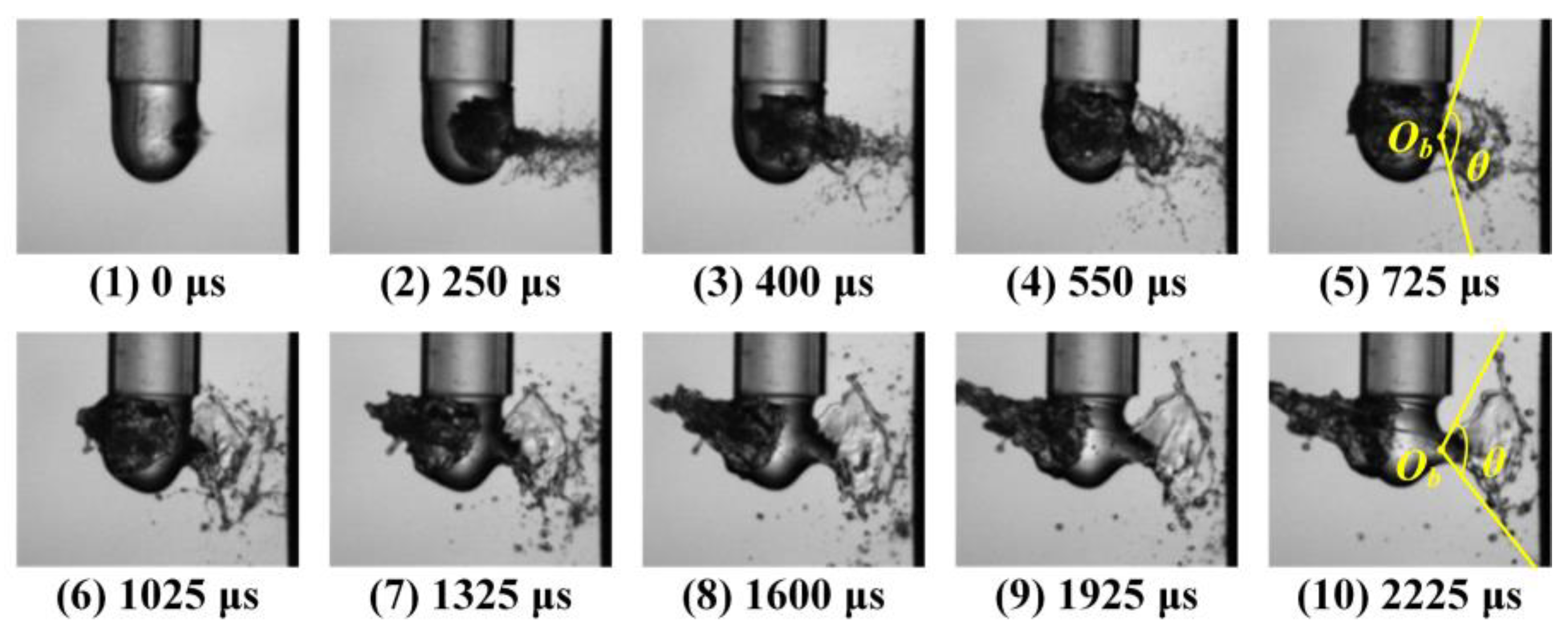
Figure 21 shows the high-speed photographs of the splash angle changes in case 3 for εX = 0.99. Its main features are given as follows: the bubble cloud moves to the left, and the horn splash of the droplet moves to the right. Therefore, the direction of the bubble collapse is opposite to the droplet splash. Among them, subfigures 1–2 show that at the first collapse stage, the center of the bubble moves to the left, and a root shape splash occurs on the right side of the droplet. Subfigure 3 shows the second collapse of the bubble, with the range of root shape splash of the droplet gradually expanding. Subfigure 4 shows the third collapse of the bubble, with the splash changing from a root shape to a horn shape. Subfigures 5–10 show the later collapse stage of bubble. It can be seen that the angle of the droplet splash gradually decreases and finally becomes a horn splash.
In order to further explore the relationship between the splash of the droplet and time, the angle of the droplet splash is defined as θ. In Figure 21, for examples (referring to t = 725 μs and t = 2225 μs), Ob shows the initial position of the bubble and the angle θ is defined as the angle of droplet splash.
Figure 22 shows the variation of the angle of droplet splash with time for the case 3. Among them, the splash angle of the droplet increases first and then decreases. From 0 μs to 1025 μs, the increase slows down, reaching a maximum of 132°. Afterwards, the angle slowly decreases, reaching a minimum splash angle of 104°.

6. Bubble Collapse Time

Figure 23 shows comparisons of bubble collapse times with three different eccentricities. Among them, the horizontal axis represents the bubble collapse time, and the vertical axis represents the instantaneous radius of the bubble. Here, τ (referring to Appendix A for the definition) represents the modification coefficient of the collapse time. In the experiments, as the droplet splash changes from case 1 to case 3, the collapse time of the bubble gradually increases, and the corresponding modification coefficient gradually increases. As shown in Figure 23, eccentricity significantly affect on the the bubble collapse time.
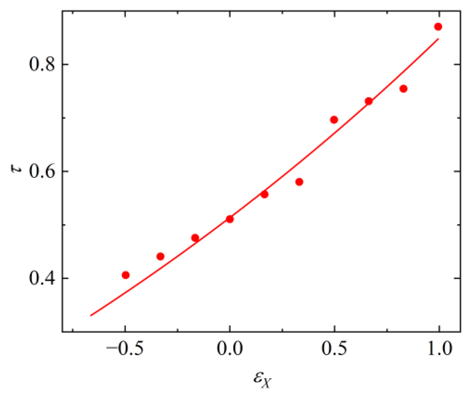
Figure 24 shows the influence of eccentricity on the modification coefficient of the collapse time with curve-fitted. Wherein, the abscissa is the eccentricity εX, and the ordinate is τ. It can be found that, with the increase in the eccentricity, the modification coefficient increases.

7. Conclusions

In this paper, a detailed analysis is conducted on the dynamic processes of a cavitation bubble within a droplet induced by a horizontal laser-induced eccentric bubble. Based on the splash morphology of the droplet, three typical splash processes and two atypical splash transition processes were identified for the cavitation bubble within the droplet. The following conclusions can be drawn:
  • The forms of droplet splash can be divided into three types: scattered splash, trident splash, and composite splash. And, the movement trend of the cavitation bubble wall can be divided into three categories: spherical, fabiform, and ellipsoidal contraction.
  • The main peak height and angle of the droplet splash could be significantly affected by the eccentricity.
  • The modification coefficient of the collapse time increases with the increase of eccentricity.

Author Contributions

Conceptualization, Y.Z. (Yuning Zhang 1) and X.Z.; methodology, Y.Z. (Yuning Zhang 1), and X.Z.; software, X.Z.; formal analysis, X.Z.; investigation, X.Z., S.Z., Y.Y., and X.D.; resources, Y.Z. (Yuning Zhang 1); data curation, X.Z.; writing—original draft preparation, X.Z.; writing—review and editing, Y.Z. (Yuning Zhang 1), Z.L. and Y.Z. (Yuning Zhang 2); visualization, S.Z., Y.Y., and X.D.; supervision, Y.Z. (Yuning Zhang 1) and Y.Z. (Yuning Zhang 2); project administration, Y.Z. (Yuning Zhang 1); funding acquisition, Y.Z. (Yuning Zhang 1) and Y.Z. (Yuning Zhang 2). All authors have read and agreed to the published version of the manuscript.

Funding

This research was financially supported by the National Natural Science Foundation of China (Project Nos.: 51976056 and 52076215).

Data Availability Statement

Not applicable.

Acknowledgments

In this paper, the authors would like to thank Hongbo Wang, Jiaze Ying, and kehui Zha for their help for the experimental data processing.

Conflicts of Interest

The authors declare no conflict of interest.

Appendix A. Theory of Modification Coefficient

The theoretical collapse time expression of the droplet bubble is as follows:
T C = τ R b max ρ Δ p 1 2
Δ P = P P V
where TC represents the collapse time, τ represents the modification coefficient of the collapse time, Rbmax represents the maximum radius of the bubble, P is the ambient pressure with 101,325 Pa, and PV is the vapor pressure with 2335 Pa.

References

  1. Wu, X.; Wang, S. Analysis and Improvement of Throttling Orifice for Recirculating Pipeline in the JND System of NPP. Nucl. Sci. Eng. 2022, 42, 533–538. [Google Scholar]
  2. Song, Y.; Lu, D.; Qin, H.; Zhong, D.; Cao, Q. Numerical Analysis on Pressure Drop of the Labyrinth Throttle. Nucl. Sci. Eng. 2020, 40, 316–324. [Google Scholar]
  3. Hu, W. Oscillation Analysis and Design Optimization of Condensate Main Control Valve. Nucl. Sci. Eng. 2022, 42, 427–435. [Google Scholar]
  4. Wang, X.; Liu, Y.; Zhu, R. Study on shaft-block under small break loss of coolant accident of nuclear main pump. Ann. Nucl. Energy 2019, 131, 344–352. [Google Scholar] [CrossRef]
  5. Hong, F.; Yuan, J.; Zhang, J.; Lu, J.; Zhang, Y. Numerical analysis of cavitating flow characteristics in residual heat removal pumps during the SBLOCA. J. Harbin Eng. Univ. 2015, 36, 297–301. [Google Scholar]
  6. Tao, J.; Xian, C.; Chen, J.; Ma, Z. Study on Aerosol Gravitational Sedimentation Characteristics in Containment of HPR. Nucl. Sci. Eng. 2020, 40, 751–756. [Google Scholar]
  7. Sun, X.; Ji, S.; Chen, L.; Shi, X.; Xiao, Z.; Wei, Y. Development of Aerosol Re-suspension Module in CABSA by Force Balance Model. Numerical Analysis on Pressure. Nucl. Sci. Eng. 2020, 40, 683–687. [Google Scholar]
  8. Ren, H.; Li, Y.; Yu, J.; Liang, F.; Li, S. Current Situation and Prospect of Radioactive Aerosol Removal Technology. Environ. Sci. Manag. 2020, 45, 92–96. [Google Scholar]
  9. Wu, H.; Wang, C.; Zheng, G.; Pang, H.; Luo, Z.; Chen, R.; Chen, L.; Wang, Z. Study on the optimization of sample introduction flow rate for aerosol direct injection device and aerosol loss rate. Radiat. Prot. 2021, 41, 27–32. [Google Scholar]
  10. Su, Y.; Li, Z.; Xu, J.; Zhai, L.; Zhu, F. Direct Introduction of Airborne and Suspension Particles into ICP-MS for on-line Elemental or Isotopic Analysis and Its Applications in Nuclear Field. Northwest Inst. Nucl. Technol. 2019, 40, 447–459. [Google Scholar]
  11. Brennen, C.E. Cavitation and Bubble Dynamics, 2nd ed.; Cambridge University Press: New York, NY, USA, 2014; pp. 80–195. [Google Scholar]
  12. Avila, S.R.G.; Ohl, C. Cavitation-induced fragmentation of an acoustically-levitated droplet. J. Phys. Conf. Ser. 2015, 656, 12017. [Google Scholar] [CrossRef]
  13. Farhat, M. What We Learned from Cavitation Bubbles in Microgravity, 1st ed.; IntechOpen: London, UK, 2020; pp. 1–20. [Google Scholar]
  14. Lindinger, A.; Hagen, J.; Socaciu, L.D.; Bernhardt, T.M.; Woste, L.; Duft, D.; Leisner, T. Time-resolved explosion dynamics of H2O droplets induced by femtosecond laser pulses. Appl. Opt. 2004, 43, 5263–5269. [Google Scholar] [CrossRef] [PubMed]
  15. Zhang, A.; Ren, S.; Li, Q.; Li, J. 3D numerical simulation on fluid-structure interaction of structure subjected to underwater explosion with cavitation. Appl. Math. Mech. 2012, 33, 1191–1206. [Google Scholar] [CrossRef]
  16. Zhang, A.; Yao, X. The interaction between multiple underwater explosion bubbles near free surface. Chin. J. Theor. Appl. Mech. 2008, 40, 26–34. [Google Scholar]
  17. Chahine, G.L. Spark-generated bubbles as laboratpry-scale models of underwater explosions and their use for validation of simulation tools. In Proceedings of the 66th Shock and Vibrations Symposium, Biloxi, MS, USA, November 1995; pp. 265–276. [Google Scholar]
  18. Eickmans, J.H.; Hsieh, W.F.; Chang, R.K. Laser-induced explosion of H2O droplets: Spatially resolved spectra. Opt. Lett. 1987, 12, 22–24. [Google Scholar] [CrossRef]
  19. Ohl, C.; Arora, M.; Dijkink, R.; Janve, V.; Lohse, D. Surface cleaning from laser-induced cavitation bubbles. Appl. Phys. Lett. 2006, 89, 74102. [Google Scholar] [CrossRef] [Green Version]
  20. Kondo, T.; Ando, K. One-way-coupling simulation of cavitation accompanied by high-speed droplet impact. Phys. Fluids 2016, 28, 33303. [Google Scholar] [CrossRef]
  21. Gonzalez Avila, S.R.; Ohl, C. Fragmentation of acoustically levitating droplets by laser-induced cavitation bubbles. J. Fluid Mech. 2016, 805, 551–576. [Google Scholar] [CrossRef]
  22. Marston, J.O.; Thoroddsen, S.T. Laser-induced micro-jetting from armored droplets. Exp. Fluids 2015, 56, 140. [Google Scholar] [CrossRef]
  23. Zeng, Q.; Gonzalez-Avila, S.R.; Voorde, S.T.; Ohl, C. Jetting of viscous droplets from cavitation-induced Rayleigh–Taylor instability. J. Fluid Mech. 2018, 846, 916–943. [Google Scholar] [CrossRef]
  24. Guo, W.; Li, H.; Wang, J.; Wang, Y.; Huang, C. Reaserch progress on interaction between a single cavitation and free surface. Chin. J. Theor. Appl. Mech. 2019, 51, 1682–1698. [Google Scholar]
  25. Obreschkow, D.; Kobel, P.; Dorsaz, N.; de Bosset, A.; Nicollier, C.; Farhat, M. Cavitation bubble dynamics inside liquid drops in microgravity. Phys. Rev. Lett. 2006, 97, 94502. [Google Scholar] [CrossRef] [PubMed] [Green Version]
  26. Farhat, M.; Obreschkow, D.; Kobel, P.; Dorsaz, N.; de Bosset, A. Interaction of a cavitation bubble with a spherical free surface. In Proceedings of the 6th International Symposium on Cavitation CAV2006, Wageningen, The Netherlands, 11–15 September 2006. [Google Scholar]
  27. Kobel, P.; Obreschkow, D.; de Bosset, A.; Dorsaz, N.; Farhat, M. Techniques for generating centimetric drops in microgravity and application to cavitation studies. Exp. Fluids 2009, 47, 39–48. [Google Scholar] [CrossRef] [Green Version]
  28. Robert, E.; Lettry, J.; Farhat, M.; Monkewitz, P.A.; Avellan, F. Cavitation bubble behavior inside a liquid jet. Phys. Fluids 2007, 19, 67106. [Google Scholar] [CrossRef]
  29. Padilla-Martinez, J.P.; Ramirez-San-Juan, J.C.; Berrospe-Rodriguez, C.; Korneev, N.; Aguilar, G.; Zaca-Moran, P.; Ramos-Garcia, R. Controllable direction of liquid jets generated by thermocavitation within a droplet. Appl. Opt. 2017, 56, 7167–7173. [Google Scholar] [CrossRef]
  30. Thoroddsen, S.T.; Takehara, K.; Etoh, T.G.; Ohl, C.D. Spray and microjets produced by focusing a laser pulse into a hemispherical drop. Phys. Fluids 2009, 21, 112101. [Google Scholar] [CrossRef] [Green Version]
  31. Liu, Y. Investigation on the Interaction of a Shock and a Liquid Droplet with and without a Vapor Cavity Inside. Ph.D. Thesis, Hong Kong Polytechnic University, Hong Kong, China, 2021. [Google Scholar]
Figure 1. Experimental platform system for laser-induced eccentric cavitation bubble within droplet.
Symmetry 15 01375 g001
Figure 2. The definition of experimental parameters.
Symmetry 15 01375 g002
Figure 3. High-speed photographs of the typical processes of droplet splash in case 1 (εX = 0.17).
Symmetry 15 01375 g003
Figure 4. High-speed photographs of the typical droplet splash processes in case 2 (εX = 0.50).
Symmetry 15 01375 g004
Figure 5. High-speed photographs of the typical droplet splash processes in case 3 (εX = 0.99).
Symmetry 15 01375 g005
Figure 6. High-speed photographs of the transition processes between case 1 and case 2 (εX = 0.33).
Symmetry 15 01375 g006
Figure 7. High-speed photographs of the transition processes between case 2 and case 3 (εX = 0.83).
Symmetry 15 01375 g007
Figure 8. Outline of the growth processes of bubble for the case 1 (εX = 0.17).
Symmetry 15 01375 g008
Figure 9. Outline of the first collapse process of bubble for the case 1 (εX = 0.17).
Symmetry 15 01375 g009
Figure 10. Outline of the growth processes of bubble for the case 2 (εX = 0.50).
Symmetry 15 01375 g010
Figure 11. Outline of the first collapse processes of bubble for the case 2 (εX = 0.50).
Symmetry 15 01375 g011
Figure 12. Outline of the growth processes of bubble for the case 3 (εX = 0.99).
Symmetry 15 01375 g012
Figure 13. Outline of the first collapse process of bubble in case 3 (εX = 0.99).
Symmetry 15 01375 g013
Figure 14. Angle diagram of the main peak of droplet splash for the case 1 (εX = 0.17).
Symmetry 15 01375 g014
Figure 15. The images of boundary of bubble and droplet in the −20° direction for the case 1 (εX = 0.17).
Symmetry 15 01375 g015
Figure 16. Angle diagram of the main peak of droplet splash for the case 2 (εX = 0.50).
Symmetry 15 01375 g016
Figure 17. The composite image of boundary of bubble and droplet in the −33° direction for the case 2 (εX = 0.50).
Symmetry 15 01375 g017
Figure 18. Angle diagram of the main peak of droplet splash for the case 3 (εX = 0.99).
Symmetry 15 01375 g018
Figure 19. The images of boundary of bubble and droplet in the −22° direction for the case 3 (εX = 0.99).
Symmetry 15 01375 g019
Figure 20. The variation of the height of the main peak of droplet splash with time.
Symmetry 15 01375 g020
Figure 21. High-speed photographs of the process of splash angle change for the case 3 (εX = 0.99).
Symmetry 15 01375 g021
Figure 22. Variation of angle of droplet splash with time for the case 3 (εX = 0.99).
Symmetry 15 01375 g022
Figure 23. Comparisons of bubble collapse time with different eccentricities.
Symmetry 15 01375 g023
Figure 24. The influences of eccentricity on the modification coefficients of collapse time.
Symmetry 15 01375 g024
Disclaimer/Publisher’s Note: The statements, opinions and data contained in all publications are solely those of the individual author(s) and contributor(s) and not of MDPI and/or the editor(s). MDPI and/or the editor(s) disclaim responsibility for any injury to people or property resulting from any ideas, methods, instructions or products referred to in the content.