1. Introduction
In recent years, the market demand for ultralarge-diameter shield tunnels (where the diameter of the shield is larger than 14 m) in China has become stronger and stronger due to its advantage of alleviating traffic pressure during the process of urbanization. According to the statistical data [
1], 56 tunnels were excavated by ultralarge-diameter shield tunnelling machines worldwide by 2020, of which 39 are in China. Ultralarge-diameter shield tunnels have gradually become the first choice for urban traffic tunnel construction in China.
During the excavation of the tunnel, the stratum and stress field are disturbed, and ground surface settlement is induced. For ultralarge-diameter shields in particular, the ground disturbance caused by tunnel excavation is larger. It is very important to accurately analyze the ground deformation caused by shield construction to control the damage to existing buildings and pipelines. At present, the most common methods for evaluating ground movement induced by tunneling are analytical methods, empirical methods, numerical methods, and physical modeling approaches [
2].
Empirical methods are based on the formula for the relationship between the maximum settlement and volume loss established by Peck [
3], and they have been improved and developed by many scholars and engineers through indepth research in theory and engineering practice [
4,
5,
6,
7,
8,
9,
10,
11,
12]. Although empirical methods have been the most widely used methods for calculating ground settlement induced by tunneling, they usually do not consider the mechanical properties of the surrounding rock directly and cannot calculate ground settlement during tunneling. With the rapid development of computer technology, advanced numerical tools that are able to model and analyze the process of tunnel construction directly and in detail, have been developed and popularized. Numerical methods play an important role in the study of ground deformation induced by tunnel excavation. The numerical methods can simulate the tunnel construction process to varying degrees due to their flexibility, however, the calculation results are influenced strongly by the rationality and applicability of the assumptions about the soil due to the complexity of the strata around the tunnels [
13,
14,
15,
16,
17,
18,
19,
20]. Analytical approaches can consider the mechanical properties of the soil around the tunnels according to the deformation characteristics of soil mass. However, analytical methods [
21,
22,
23,
24,
25,
26] basically assume that the surrounding stratum is uniform and under axisymmetric plane strain, which makes it difficult to simulate the construction process. Thus, the application of analytical methods is limited. With the improvement of test conditions and techniques, more and more physical model experiments have been carried out to study the influence of tunnel constructions, e.g., laboratory-scale model tests, geotechnical centrifuge model experiments, and full-scale field experiments [
27,
28,
29,
30,
31]. Physical model testing, as an intuitive and directly experimental method, plays an important part in scientific research. However, with the increasing complexity of practical tunnel engineering, the simplifications made in the model have an important impact on the accuracy of the experimental results.
These commonly used methods have their own obvious advantages and limitations in analyzing the ground deformation caused by tunneling. In order to obtain a more proper influence of shield construction on the railway subgrade, this paper presents a study on the railway subgrade settlement induced by an ultralarge-diameter shield tunnel (with a shield diameter larger than 16.0 m) using an empirical method, numerical simulation, and geotechnical centrifuge model test. By comparing the results obtained from those methods, the rationality of the settlement predictions is discussed, which could provide reference significance for tunnel construction and controlling subgrade settlement.
2. Engineering Background
The Wuhan Lianghu Highway Tunnel project is currently the largest double-layer tunnel under lakes (East Lake and South Lake in Wuhan) in the world. It is located in the south area of Wuhan City, the capital of Hubei province in China. This project is designed to connect the north and south sides of the Wuchang area directly and more conveniently and to improve the trunk road network of the Wuchang area (
Figure 1). The Lianghu Tunnel project is 19.25 km long in total and includes the East Lake section and South Lake section. With a diameter of about 16.2 m, the shield machine used in the project is the largest-diameter Slurry Pressure Balance machine in China at present. The construction of the underground section of the Lianghu tunnel project takes place not only in the area of the two lakes, but also in a densely populated area, under hundreds of buildings, arterial roads, utilities, and an intercity railway, the Wuxian Railway. During construction with such large-diameter shield machines, the impact is very difficult to control, especially on the Wuxian Railway, which lies above the Lianghu tunnel (South Lake section) with a minimum vertical distance of only about 16.5 m (
Figure 2). The Wuxian Railway is a fast intercity railway connection between Wuhan and Xianning in Wuhan City. The design speed is 250 km/h, with a reserved speed of 300 km/h. The angle between the Lianghu tunnel alignment and Wuxian Railway is about 61°, and the closest distance between TBM launch shaft No. 6 and the Wuxian Railway tracks is about 37 m (
Figure 3).
According to the geological survey report, the strata between the No. 6 shaft and the intercity railway area are mainly plain fill, miscellaneous fill, gravel soil, mudstone, mudstone with sandstone, and quartz sandstone (
Figure 4).
For the railway subgrade, its dimension can be determined, as shown in
Figure 5, according to the China National Code for Design of Railway Subgrade [
32] for a double-track ballasted track (designed at a speed of 250 km/h).
3. Empirical Method and Estimation
The application of the normal distribution curve for the calculation of transverse settlement profiles was proposed by Peck [
3], O’Reilly, and New [
5]. The settlement trough induced by tunnel excavation is described by the well-established Gaussian settlement curve. The curve is calculated by the following equation:
where
Sv,max is the maximum settlement of the settlement trough,
y is the horizontal distance from the tunnel center line (transverse direction),
i is the horizontal distance between the tunnel axis and the point of inflection of the settlement trough, and
Sv,max and
i are defined as in the following equations:
where
VL is volume loss that defines the volume (area in 2D conditions) of ground which is excavated in excess of the nominal tunnel volume (2D: tunnel face area),
r is the tunnel radius,
K is the settlement trough width factor that calculates the width of the settlement trough, and
h0 is the vertical distance between the tunnel axis and ground surface or foundation level.
It can be seen that there are two key input parameters VL and K which control the shape and magnitude of the surface settlement trough. The volume loss VL is related to the excavation method (e.g., shield type, operation mode, etc.) and the ground conditions, while the parameter, K, basically depends on the ground type.
Many studies based on field measurements show that the value of
VL varies between 0% and 3% depending on the tunneling methods [
3,
5,
33,
34,
35,
36,
37]. The volume loss by Slurry type shields is usually smaller than that by EPB (Earth Pressure Boring machine). Studies on the settlement trough width factor [
6,
9,
38] show that
K varies from 0.2 to 0.3 for granular soils through to 0.4 to 0.5 for stiff clays, while for soft silt clays,
K can reach values of 0.7. Chiriotti and Grasso [
39] used a matrix approach methodology to develop a matrix assessing the
VL and
K parameters in nonconventional media for TBM tunneling, considering the scenarios resulting from various combinations of face and overburden conditions.
Based on the geological survey at the Lianghu tunnel undercrossing the intercity railway section, the rock mass where the SPB shield drives is classified as grade IV~VI, and the tunnel face can be identified as weak rock. The soil conditions between the tunnel and the railway can be presumed as mixed geology. Then, according to the matrix approach proposed by Chiriotti and Grasso [
39], the value of
VL is smaller than 0.5% and the value of
K is 0.5~0.7. Moreover, the measurement data of the maximum ground settlement caused by tunnel construction in 23 regions of China show that the
VL caused by an SPB machine is between 0% and 1.0% [
36]. Thus, the following settlement trough parameters
K and
VL are proposed in
Table 1.
The ground settlement at the section with minimum overburden (16.5 m) can be calculated using Equations (1)–(3).
Figure 6 shows the ground settlement curves estimated by the empirical method. It can be seen that the maximum settlement induced by tunneling is about 10 mm under favorable geological and construction conditions (ideal-case scenario), about 22 mm under probable geological and construction conditions (most likely scenario), and up to 66 mm under the worst possible conditions (worst-case scenario).
4. Experimental Method and Test Results
4.1. Centrifuge Model Test Set-Up
A centrifuge model test uses centrifugal force to simulate gravity so that a similar stress state as the prototype can be recreated in a small-scale soil model by increasing its gravitational acceleration. In centrifuge modeling, the relationship between a model and a prototype can be derived according to similarity theory.
In this study, the centrifuge test was carried out at the Centrifuge Laboratory of the China Institutes of Water Resources and Hydropower Research [
40]. The 450 g-ton centrifuge has an arm radius of 5.03 m, and its maximum acceleration can reach 300 g. The centrifuge test in this study was carried out at an acceleration of 60 g using a model container with a net size of 600 mm × 350 mm × 650 mm (length × width × height), as
Figure 7 shows. Scale factors (between the prototype and model scale) relevant to this study are summarized in
Table 2.
According to the similitude theory, the relationship among the scale factors is as follows:
where
Cσ is the scale factor of stress,
CE is the scale factor of elastic modulus,
Cε is the scale factor of strain,
CL is the scale factor of geometry,
Cρ is the scale factor of density, and
N is the centrifugal acceleration level.
In the centrifugal test, the diameter of the outer cylinder modeling the cutter head diameter was 80 mm, thus the geometry scale factor
CL was about 16.2/0.08 = 202. To facilitate the discussion of test results, a strain scale
Cε = 1 was selected. The Young’s modulus of the material used to model mudstone with sandstone was about 23 MPa, therefore the model scale factor of elastic modulus
CE was about 90/23 = 4. The density of the material used to model mudstone with sandstone was 2.17 g/cm
3 and the corresponding model scale factor of density
Cρ was about = 2.56/2.17 = 1.18. Using the above formula, the scale factor of stress and the centrifugal acceleration level can be calculated as 4 and 60, respectively [
40].
The layout and the dimensions of the model are presented in
Figure 8. The model represents a prototype where a shield tunnel with an ultralarge diameter was constructed obliquely undercrossing the railway subgrade. The vertical clearance from the crown of the shield tunnel to the bottom of the railway subgrade was set at 1D (where D is the diameter of the shield tunnel). It should be noted that there are some differences between the centrifuge model and the prototype. First, the four layers of the prototype subgrade were simplified into one layer due to the limitations of the model box, and the physical and mechanical parameters of the foundation base were used for unfavorable conditions. Second, the miscellaneous fill layer and plain fill layer in the prototype were not modeled because they are quite thin and extremely difficult to model. Thus, only two layers of the tunnel overburden were modeled, e.g., gravel soil and mudstone with a sandstone layer. In order to consider the most unfavorable stratum conditions of the shield tunnel passing through the intercity railway, the quartz stone was replaced by mudstone with sandstone with poor properties.
Moreover, it should be noted that the traffic load could have an influence during tunnel excavation. Thus, the traffic load was considered in the model for unfavorable conditions. Since the train’s dynamic load is difficult to model in the test, the weight of the track and the dynamic load of the train were regarded as a uniformly distributed static load acting on the subgrade. Based on the China National Code for Design of Railway Subgrade [
30], the dead weight of the railway and the train load are 17.3 kPa and 36.8 kPa, respectively, and the total load is 54.1 kPa. In order to model the uniformly distributed load on the subgrade, including the dead weight load of the track structure and the train load, loads were piled on the subgrade surface along the subgrade line. The total mass of the surcharge was 2 kg, and the load applied to the subgrade surface at the centrifugal acceleration of 60 g was 13.5 kPa. According to the stress scale factor
Cσ = 4, the corresponding prototype load was 54.1 kPa.
4.2. Data Acquisition
Although there are four intercity railway tracks, it is difficult to monitor all four tracks due to the size limitation of the model. Only the centerline of the railway subgrade was selected as the main monitoring line. The line along the tunnel axis and the line perpendicular to the tunnel axis were also monitored. The layout of the monitoring points is shown in
Figure 9. In total, seven laser displacement sensors measured the surface displacement along the subgrade, the tunnel axis, and the line perpendicular to the tunnel axis with an accuracy of 8 μm.
4.3. Experimental Results
Figure 10 and
Figure 11 show the settlement patterns along the subgrade and the cross section at the crossing point with the tunnel excavation, respectively. They are apparently consistent with the common surface settlement trough form caused by tunnel excavation. It can be also seen that the settlement along the subgrade and the cross section at the crossing point increase with tunneling, and the maximum settlement due to the excavation is about 65 mm. Moreover, the settlement along the cross section at the crossing point is symmetric, while the settlement along the subgrade is asymmetric. Clearly, this is due to the railway and the tunnel axis intersecting at an angle of 61°.
5. Numerical Modeling and Prediction
5.1. Numerical Model
A three-dimensional numerical model of the shield tunnel and intercity railway subgrade was established using the finite element program Plaxis 3D. The model dimensions were 180 m × 200 m × 90 m in the X, Y, and Z directions, respectively, as
Figure 12 shows. The top surface of the model had a free stress border, the bottom of the model was restrained, and the horizontal displacements in the vertical boundaries were fixed. The tunnel was excavated in the Y direction. The element length of the tunnel in the Y-direction was set as 1.5 m, the same as the width of the segmental lining. To improve the efficiency of computation, the model was meshed in a finer manner around the tunnel and the railway subgrade, while the meshed elements under and away from the tunnel became coarser gradually with a default factor provided in Plaxis 3D. A 10-node element is used for the 3D modeling of solid structures. The model had 160,821 elements and 244,766 nodes and is shown in
Figure 12.
The adopted constitutive model for all soil layers was an elastic—perfectly plastic Mohr—Coulomb model, and the parameters of all the soil layers used in the simulation are presented in
Table 3. The strata under the intercity railway were inferred from the geological drilling holes near the railway due to no drilling being allowed in the strata under the railway. The corresponding geological properties are adopted in
Table 3 based on the geotechnical engineering geological investigation report. Therefore, the adopted properties correspond to the most likely case.
According to the tunnel design, the thickness of the segmental lining is 65 cm, the strength of the lining concrete is C60, and the corresponding elastic modulus is 3.24 × 10⁷ kPa. In the numerical simulation, the segmental lining was simulated by solid elements as an elastic material. Considering the influence of segment joints, a reduction coefficient of 0.9 for the elastic modulus was adopted. The shield was simulated by plate elements, which are regarded as an elastic material. The elastic modulus of the plate elements is 2.3 × 10⁸ kPa, with a unit weight of 120 kN/m3 and a thickness of 0.55 m. In order to simulate the soil-structure interaction on the outer side of the tunnel, a negative interface was created at the outer torus of the segmental lining at the same time a surface contraction was also applied. The surface contraction could represent the volume loss during the excavation of the tunnel.
The dimensions and strata of the railway subgrade were determined according to the China National Code for Design of Railway Subgrade [
32] (see
Figure 5). All the subgrade layers were modeled as an elastic—perfectly plastic material, except for the ballast layer, which was modeled as an elastic model. The corresponding physical and mechanical properties of the railway subgrade are listed in
Table 4. The dead weight load of 17.3 kPa of the railway is applied to the subgrade in the simulation.
5.2. Numerical Simulation Process
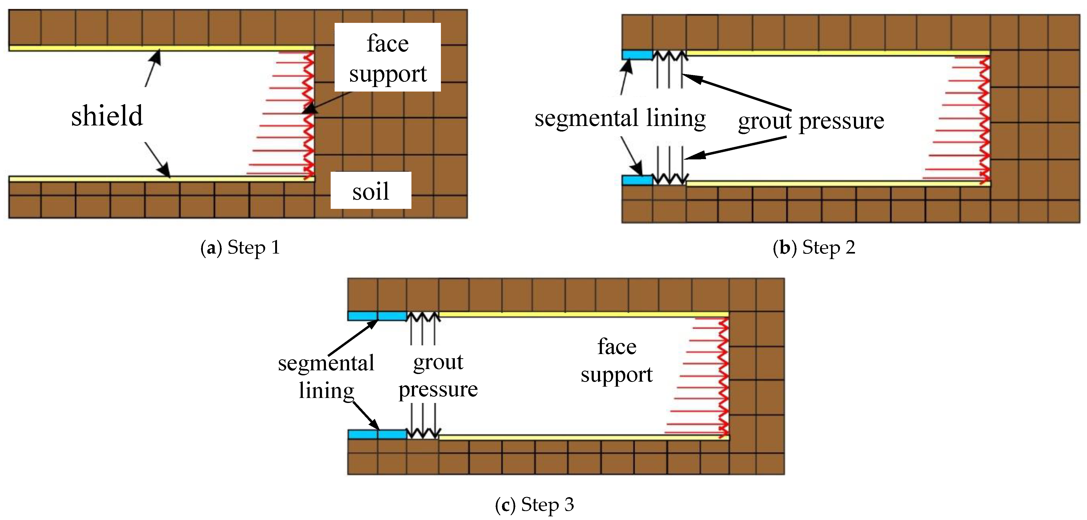
The excavation of the shield tunnel was simulated step by step, and the excavation length of every step was designed to be the width of a shield segment as
Figure 13 shows. First, in Step 1, the soil was removed. Then shield push pressure was applied at the tunnel face and the shield shell was installed to support the soil (see
Figure 13a). In order to simulate the volume loss caused by excavation, a contraction of 0.5% was applied to the shield. Second, in Step 2, the pressure and the shield were unloaded, and the segmental lining was installed with the application of grouting pressure (see
Figure 13b). And Step 3 is to repeat steps one and two until the tunnel was completed (see
Figure 13c). The deformations of the ground and soil around the tunnel at each step were calculated.
It is known that the value of shield push pressure is related to the lateral static earth pressure. Considering such a large-diameter shield tunnel, a trapezoidal tunnel face support pressure was applied during the simulation, as
Figure 14 shows. The support pressure at the tunnel crown was set as the lateral static earth pressure of this position, i.e., P
ft = 216.7 kPa, and the support pressure was increased with tunnel face depth at the rate of 26.3 kP/m. Thus, the support pressure at tunnel invert P
fb was about 624.35 kPa.
Generally, the grouting pressure should not be less than the water and earth pressures on the segmental lining so that the slurry can effectively fill the void at the shield tail. A reasonable grouting pressure and distribution form can effectively control the deformation of the supporting structure and minimize its deformation, thus reducing the impact on the surface settlement. The optimal state is that the grouting layer is evenly wrapped around the segments. However, in practical engineering, there is a nonuniform grouting pressure mode. Therefore, in this simulation, a nonuniform grouting pressure mode was adopted, as shown in
Figure 15, in which the grouting pressure at the tunnel crown was set to 1.5 times the lateral static earth pressure at this position, i.e., p
gt = 324 kPa, and the grouting pressure increased with tunnel depth at the rate of 10 kPa/m. Thus, the grouting pressure at tunnel invert p
gb was about 479 kPa.
5.3. Monitoring Plan
To facilitate comparison with the results of the other methods, two monitoring lines (L1 and L2) were selected, as
Figure 16 shows. The settlements along these two lines were recorded during the simulation. L1 locates at the subgrade surface along the first track, and L2 represents the cross section at the crossing point with Track1 (see
Figure 16).
5.4. Numerical Results
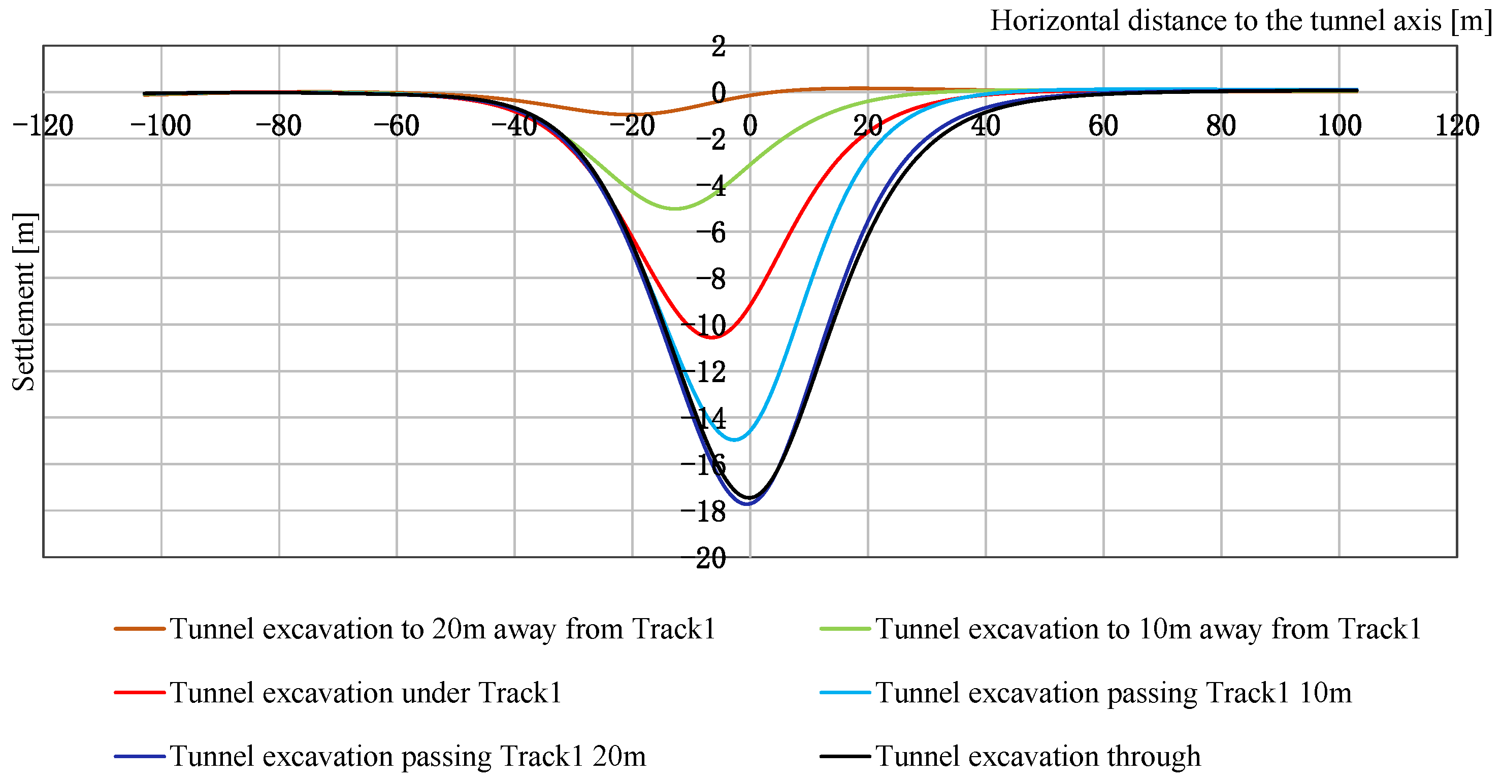
Figure 17 and
Figure 18 show the settlement patterns along L1 (Track1) and L2 (the cross section at the crossing point with Track1), respectively, during tunnel excavation. It can be seen that the maximum settlement along the railway subgrade due to tunnel excavation is about 18 mm. As
Figure 17 shows, the settlement along L1 shows apparent asymmetry, while the asymmetry gradually weakens and eventually disappears with tunnel excavation passing the railway subgrade. It can be also seen that the differential settlement of the railway subgrade increases with the advance of the shield machine. The differential settlement of the railway subgrade would exceed the differential settlement allowed by the China National Code for Design of Railway Subgrade (5 mm/10 m) [
32] when the tunnel is excavated passing Track1 (see
Figure 16) by 10 m. The maximum differential settlement of the railway subgrade is about 7 mm/10 m. This indicates that some mitigation measures should be adopted to reduce the effect of tunnel excavation on the railway subgrade.
6. Comparisons and Discussions
In order to compare the results obtained from the three analysis methods, the cross section at the crossing point with the subgrade was selected, where the depth of overburden is smallest.
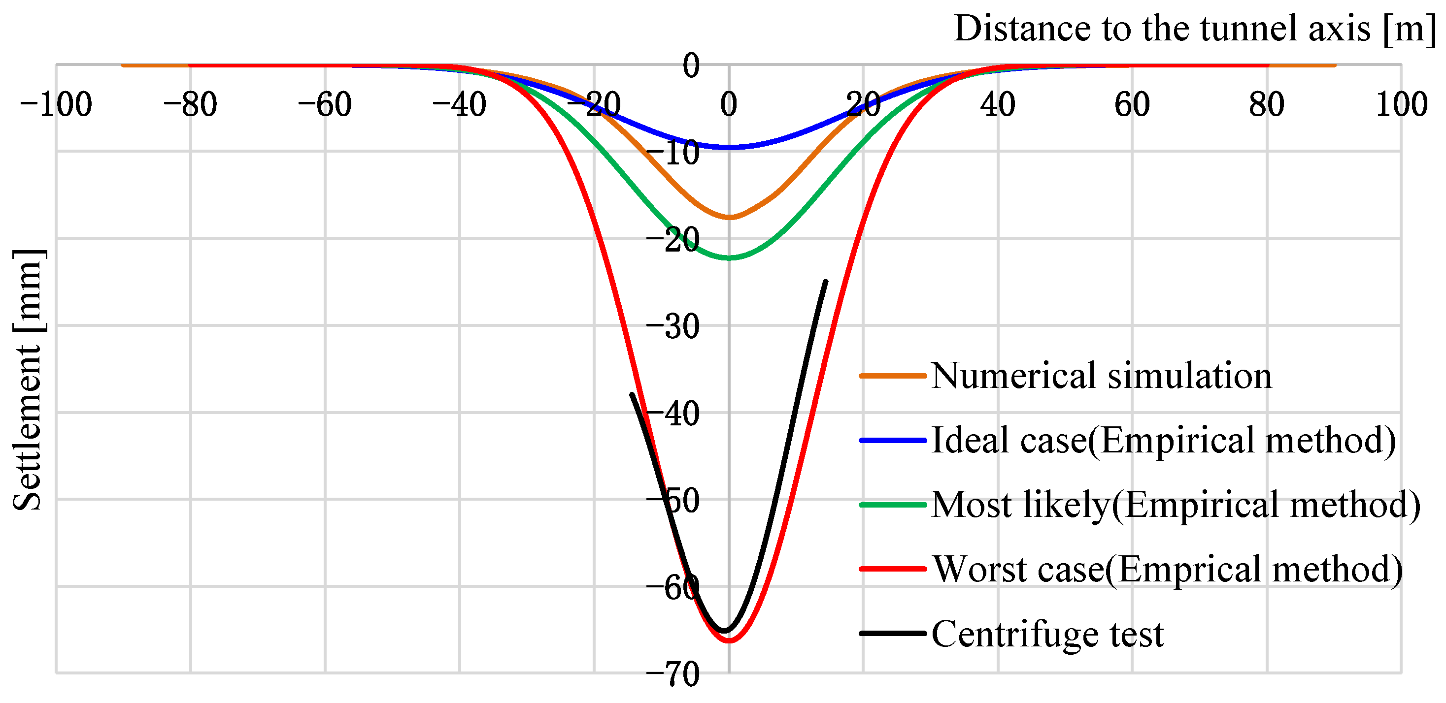
Figure 19 shows a comparison of the ground settlement results perpendicular to the tunnel axis obtained from the empirical method, centrifuge test, and numerical simulations.
It can be seen from
Figure 19 that the results obtained from the centrifuge test (black line) match well with the results calculated by the empirical method under the worst conditions (red line). As described in
Section 4, the most unfavorable stratum conditions and traffic loads were considered in the centrifuge model. Therefore, it could be concluded that the maximum subgrade settlement under the most unfavorable conditions due to tunneling could reach 65 mm.
In comparing the results obtained from the numerical simulations with those calculated by the empirical method for the most likely case, they are quite close, which indicates that the maximum settlement of the subgrade due to tunnel excavation under probable geological and construction conditions could be about 20 mm. The numerical results of settlement along the subgrade show that the maximum differential settlement of the railway subgrade during tunnel excavation under probable geological and construction conditions would exceed the requirements of the China National Code for Design of Railway Subgrade. Moreover, it should be noted that the traffic load was not considered in the numerical simulations. The settlement of the railway subgrade due to the construction of the shield tunnel could be larger if the traffic load was considered since it is required that the construction of the shield tunnel should not affect the operation of the railway. Thus, corresponding measures for reducing the influence on the railway subgrade due to the construction of the shield tunnel must be considered, and it is suggested that the shield machine should underpass the railway subgrade during the skylight period of railway operation.
7. Conclusions
Based on the study of the influence of an ultralarge-diameter shield tunnel crossing under intercity railway subgrade using an empirical method, numerical simulations, and centrifuge model test, the following conclusions were drawn:
First, the empirical method is still a very easy and quick method for predicting ground settlement caused by the construction of a shield tunnel. The empirical method can estimate the approximate range of the influence of shield construction, however, it cannot reflect the shield construction process, so it is unable to analyze the impact of the shield construction process on the intercity railway underpass subgrade.
Second, compared with the empirical method, the numerical simulation method and the centrifuge model test method can reflect the influence of the shield construction process. Both the numerical simulation method and the geotechnical centrifuge model test method showed that the deformation of the railway subgrade increases gradually with tunneling, while the asymmetry of its settlement curve decreases gradually.
Third, for tunnel excavation under probable geological and construction conditions, the results obtained by the numerical simulation method are close to those obtained by the empirical method, however, they are obviously different from those obtained by the centrifuge model test. This is because, in the centrifuge model test, the stratum set in the model was simplified to represent the most unfavorable stratum conditions where the shield underpasses the intercity railway. This can be proved by the good agreement between the settlement value obtained from the centrifuge experiment and the result obtained from the commonly used empirical formula method for the worst-case scenario.
Fourth, all the results obtained from these three methods indicate that corresponding measures to reduce the impact of shield construction on the intercity railway subgrade should be taken, for either the worst-case scenario or the most likely scenario. The numerical results show that differential settlement of the subgrade would increase gradually with tunnel advancement and exceed the differential settlement allowed by the China National Code for Design of Railway Subgrade (5 mm/10 m) when the tunnel is excavated passing Track1 (see
Figure 16) by 10 m. Therefore, it is suggested that control measures should be taken, especially when the shield tunnel machine is about to pass under the railway subgrade. The shield machine should pass under the railway subgrade during the skylight period of railway operation.
Author Contributions
Conceptualization, M.S. and J.L.; writing—original draft preparation, M.S., X.W. and H.L.; writing—review and editing, X.W. and X.L.; funding acquisition, X.L. All authors have read and agreed to the published version of the manuscript.
Funding
This research was funded by the National Natural Science Foundation of China (No. 51938008).
Data Availability Statement
Not applicable.
Acknowledgments
The authors are deeply thankful to the reviewers for their valuable suggestions to improve the quality of the paper.
Conflicts of Interest
The authors declare no conflict of interest.
References
- Sun, H.; Feng, Y. Statistics on global super-large diameter tunnel boring machines. Tunn. Constr. 2020, 40, 925. [Google Scholar]
- Mohammed, Y.F.; Kais, T.S.; Nahla, M.S. Predication of settlement trough induced by tunneling in cohesive ground. Acta Geotech. 2013, 8, 167–179. [Google Scholar]
- Peck, R.B. Deep Excavations and Tunneling in Soft Ground. State of the Art Report. In Proceedings of the 7th International Conference on Soil Mechanics and Foundation Engineering, Mexico City, Mexico, 25–26 August 1969; pp. 225–290. [Google Scholar]
- Attewell, P.B.; Farmer, I.W. Ground deformations resulting from tunnelling in London Clay. Can. Geotech. J. 1974, 11, 380–395. [Google Scholar] [CrossRef]
- O’Reilly, M.P.; New, B.M. Settlements above tunnels in the United Kingdom their magnitude and Prediction. In Proceedings of the Tunnelling 82, 3rd International Symposium, Brighton, UK, 7–11 June 1982; IMM: London, UK, 1982; pp. 173–181. [Google Scholar]
- Mair, R.J.; Taylor, R.N.; Bracegirdle, A. Subsurface settlement profiles above tunnels in clay. Géotechnique 1993, 43, 315–320. [Google Scholar] [CrossRef]
- Harris, D.I.; Franzius, J.N. Settlement assessment of running tunnels—A generic approach. In Geotechnical Aspects of Underground Construction in Soft Ground; Balkema: Rotterdam, The Netherlands, 2006; pp. 225–230. [Google Scholar]
- Wei, G. Study on Calculation for Width Parameters of Surface Settlement Trough Induced by Shield Tunnel. Ind. Constr. 2009, 39, 74–79. [Google Scholar]
- Fu, D.M.; Zhou, W.B. Development of Engineering Technology of super-large diameter shield tunnel. Underground Transportation Projects and Work Safety. In Proceedings of the 5th China International Symposium on Tunnel Engineering, Shanghai, China, 10–12 November 2011; p. 9. [Google Scholar]
- Wang, M.T.; Wu, B.; Zhang, P.H. Calculation method of width parameters of railway subgrade settlement trough caused by shield tunnel construction. J. Fujian Inst. Technol. 2016, 14, 212–217. [Google Scholar]
- Lin, Q.; Tian, Y.; Lu, D.; Gong, Q.; Du, X.; Gao, Z. A prediction method of ground volume loss variation with depth induced by tunnel excavation. Acta Geotech. 2021, 16, 3689–3707. [Google Scholar] [CrossRef]
- Li, Y.; Lin, J.; Yan, S.; Du, J. Modification of the Peck Formula for a Double-Track Shield Tunnel under Expressway Subgrade. Symmetry 2022, 14, 1904. [Google Scholar] [CrossRef]
- Sun, J.; Liu, H.Z. 3-D Numerical Simulation of Ground Surface Settlement under Overlapped Shield Tunnelling. J. Tongji Univ. (Nat. Sci.) 2002, 30, 379–385. [Google Scholar]
- Zhang, H.B.; Yin, Z.Z.; Zhu, J.G. 3D Finite Element Simulation on Deformation of Soil Mass during Shield Tunneling. Chin. J. Rock Mech. Eng. 2005, 24, 755–760. [Google Scholar]
- Sharifzadeh, M.; Kolivand, F.; Ghorbani, M.; Yasrobi, S. Design of sequential excavation method for large span urban tunnels in soft ground—Niayesh tunnel. Tunn. Undergr. Space Technol. 2013, 35, 178–188. [Google Scholar] [CrossRef]
- Liu, X.; Fang, Q.; Zhou, Q.; Liu, Y. Predicting Ground Settlement Due to Symmetrical Tunneling trough an Energy Conservation Method. Symmetry 2018, 10, 186. [Google Scholar] [CrossRef]
- Zhao, M.; Cheng, Y.; Song, Z.; Wang, T.; Zhang, Y.; Gong, Y.; Song, Y. Stability Analysis of TBM Tunnel Undercrossing Existing High-Speed Railway Tunnel: A Case Study from Yangtaishan Tunnel of Shenzhen Metro Line 6. Adv. Civ. Eng. 2021, 2021, 6674862. [Google Scholar] [CrossRef]
- Lakirouhani, A.; Jafari, R.; Hasanzadehshooiili, H. Three-Dimensional Finite Difference Analysis on the Ground-Sequential Tunneling-Superstructure Interaction. Adv. Civ. Eng. 2021, 2021, 9464225. [Google Scholar] [CrossRef]
- Yang, Q.; Wang, B.; Guo, W. Effects of Large-Diameter Shield Tunneling on the Pile Foundations of High-Speed Railway Bridge and Soil Reinforcement Schemes. Symmetry 2022, 14, 1913. [Google Scholar] [CrossRef]
- Fu, J.; Zhao, N.; Qu, Y.; Yang, J.; Wang, S. Effects of twin tunnel undercrossing excavation on the operational high speed railway tunnel with ballastless track. Tunn. Undergr. Space Technol. 2022, 124, 104470. [Google Scholar] [CrossRef]
- Verruijt, A.; Booker, J.R. Surface settlements due to deformation of a tunnel in an elastic half plane. Geotechnique 1996, 6, 753–756. [Google Scholar] [CrossRef]
- Sagaseta, C. Analysis of undrained soil deformation due to ground loss. Geotechnique 1998, 37, 301–320. [Google Scholar] [CrossRef]
- Bobet, A. Analytical Solutions for Shallow Tunnels in Saturated Ground. J. Eng. Mech. 2001, 127, 1258–1266. [Google Scholar] [CrossRef]
- Lu, H.L.; Zhao, Z.M.; Fang, P.; Jiang, X.L. Analytical method of image theory used to calculate shield tunneling induced soil displacements and stresses. Rock Soil Mech. 2007, 28, 45–50. [Google Scholar]
- Cheng, H.Z.; Chen, J.; Chen, G.L. Analysis of ground surface settlement induced by a large EPB shield tunnelling: A case study in Beijing. China. Environ. Earth Sci. 2019, 78, 605. [Google Scholar] [CrossRef]
- Chen, R.P.; Song, X.; Meng, F.Y.; Wu, H.N.; Lin, X.T. Analytical approach to predict tunneling-induced subsurface settlement in sand considering soil arching effect. Comput. Geotech. 2022, 141, 104492. [Google Scholar] [CrossRef]
- Imamura, S.; Hagiwara, T.; Mito, K.; Nomoto, T.; Kusakabe, O. Settlement through above a model shield observed in a centrifuge. Centrifuge 1998, 2, 713–719. [Google Scholar]
- Zhou, X.W.; Pu, J.L. Centrifuge model test study of the earth pressure and deformation of tunnel lining. J. Tsinghua Univ. 2001, 41, 110–113. [Google Scholar]
- Fang, Y.; He, C.; Jiang, C.Y. Model Test of Ground Strain Disturbance Induced by Earth-pressure-balanced Shield Driving. J. China Railw. Soc. 2013, 35, 85–89. [Google Scholar]
- Weng, X.; Sun, Y.; Yan, B.; Niu, H.; Lin, R.; Zhou, S. Centrifuge testing and numerical modeling of tunnel face stability considering longitudinal slope angle and steady state seepage in soft clay. Tunn. Undergr. Space Technol. 2020, 101, 103406. [Google Scholar] [CrossRef]
- Meng, F.-Y.; Chen, R.-P.; Liu, S.-L.; Wu, H.-N. Centrifuge Modeling of Ground and Tunnel Response to Nearby Excavation in Soft Clay. J. Geotech. Geoenviron. Eng. 2021, 147, 04020178. [Google Scholar] [CrossRef]
- TB 10001-2016; China National Code for Design of Railway Subgrade. Ministry of Railways: Beijing, China, 2016.
- Clough, G.W.; Schmidt, B. The design and performance of excavation and tunnels in soft clay. In Development in Geotechnical Engineering; Elsevier: Amsterdam, The Netherlands, 1981; Volume 20, pp. 567–634. [Google Scholar]
- Mair, R.J.; Taylor, R.N.; Burland, J.B. Prediction of ground movements and assessment of risk of building damage due to bored tunnelling. In Geotechnical Aspects of Underground Construction in Soft Ground; Balkema: Rotterdam, The Netherlands, 1997; pp. 713–718. [Google Scholar]
- Attewell, P.B.; Yeates, J.; Selby, A.R. Soil Movements Induced by Tunnelling and Their Effects on Pipelines and Structures; Blackie, Chapman and Hall: New York, NY, USA, 1986. [Google Scholar]
- Wei, G. Selection and distribution of ground loss ratio induced by shield tunnel construction. Chin. J. Geotech. Eng. 2010, 32, 1345–1361. [Google Scholar]
- Wu, C.S.; Zhu, Z.Y. Statistical analysis of ground loss ratio caused by different tunnel construction methods in China. J. Zhejiang Univ. (Eng. Sci.) 2019, 53, 19–30. [Google Scholar]
- Burland, J.B. Assessment methods used in design. In Building Response to Tunnelling: Case Studies from Construction of the Jubilee Line Extension; Burland, J.B., Standing, J.R., Jardine, F.M., Eds.; Telford: London, UK, 2001. [Google Scholar]
- Chiriotti, E.; Grasso, P. Porto light metro system, lines C., S and J. Compendium to the Methodology Report on Building Risk Assessment Related to Tunnel Construction, Normetro—Transmetro, Intermal Technical Report (in English and Potuguese). 2001. [Google Scholar]
- Yang, L.S.; Liu, J.G.; Shu, H. Centrifugal Model Test on Construction Process of a Super Large Diameter Shield Tunnel Passing under Existing Railway. Mod. Tunn. Technol. 2021, 58, 170–177. [Google Scholar]
Figure 1.
The site of the Lianghu Tunnel project.
Figure 1.
The site of the Lianghu Tunnel project.
Figure 2.
Vertical position relationship at the selected section.
Figure 2.
Vertical position relationship at the selected section.
Figure 3.
Plan view of the shield tunnel and railway.
Figure 3.
Plan view of the shield tunnel and railway.
Figure 4.
Geological profile.
Figure 4.
Geological profile.
Figure 5.
Dimension of the intercity railway subgrade.
Figure 5.
Dimension of the intercity railway subgrade.
Figure 6.
Ground settlement curves estimated by the empirical method.
Figure 6.
Ground settlement curves estimated by the empirical method.
Figure 7.
Centrifuge model box.
Figure 7.
Centrifuge model box.
Figure 8.
Configuration of the centrifuge model (unit: mm): (a) Side view; (b) Top view.
Figure 8.
Configuration of the centrifuge model (unit: mm): (a) Side view; (b) Top view.
Figure 9.
Layout of monitoring points (unit: mm).
Figure 9.
Layout of monitoring points (unit: mm).
Figure 10.
Ground settlement along the subgrade.
Figure 10.
Ground settlement along the subgrade.
Figure 11.
Ground settlement along the cross section at the crossing point during tunnel excavation.
Figure 11.
Ground settlement along the cross section at the crossing point during tunnel excavation.
Figure 12.
Numerical model.
Figure 12.
Numerical model.
Figure 13.
Numerical simulation progress of tunnel excavation.
Figure 13.
Numerical simulation progress of tunnel excavation.
Figure 14.
Schematic diagram of the tunnel face support pressure.
Figure 14.
Schematic diagram of the tunnel face support pressure.
Figure 15.
Schematic diagram of the grouting pressure.
Figure 15.
Schematic diagram of the grouting pressure.
Figure 16.
Schematic of the monitoring plan.
Figure 16.
Schematic of the monitoring plan.
Figure 17.
Ground settlement along L1 during tunnel excavation.
Figure 17.
Ground settlement along L1 during tunnel excavation.
Figure 18.
Ground settlement along L2 during tunnel excavation.
Figure 18.
Ground settlement along L2 during tunnel excavation.
Figure 19.
Comparison of ground settlement perpendicular to the tunnel axis obtained from three methods.
Figure 19.
Comparison of ground settlement perpendicular to the tunnel axis obtained from three methods.
Table 1.
Proposed settlement parameters for the Lianghu tunnel.
Table 1.
Proposed settlement parameters for the Lianghu tunnel.
| Parameters | Ideal-Case Scenario | Most Likely Scenario | Worst-Case Scenario |
|---|
| VL | 0.2% | 0.5% | 1% |
| K | 0.7 | 0.6 | 0.5 |
Table 2.
Summary of scale parameters in the centrifugal model test (acceleration = 60).
Table 2.
Summary of scale parameters in the centrifugal model test (acceleration = 60).
| Parameter | Scale Factor (Model/Prototype) |
|---|
| Geometry CL | 202 |
| Elastic modulus CE | 4 |
| Density Cρ | 1.18 |
| Strain Cε | 1 |
| Stress Cσ | 4 |
| Displacement Cd | 202 |
Table 3.
Physical and mechanical parameters of each soil layer.
Table 3.
Physical and mechanical parameters of each soil layer.
| Parameter | Plain Fill | Gravel Soil | Quartz Sandstone | Mudstone with Sandstone |
|---|
| Weight density γ (kN/m3) | 19.2 | 19.5 | 25.7 | 25.6 |
| Young’s modulus E (MPa) | 5 | 25 | 900 | 90 |
| Friction angle Ø (°) | 10 | 27 | 35 | 29 |
| Cohesion c (kN/m2) | 13 | 10 | 18,400 | 200 |
| Poisson’s ratio ν | 0.2 | 0.29 | 0.23 | 0.35 |
| Lateral pressure coefficient | 0.65 | 0.40 | 0.50 | 0.50 |
Table 4.
Physical and mechanical parameters of railway subgrade.
Table 4.
Physical and mechanical parameters of railway subgrade.
| Parameter | Ballast Layer | Surface Layer | Bottom Layer | Foundation Base |
|---|
| Weight density γ (kN/m3) | 18 | 22 | 21 | 20 |
| Young’s modulus E (MPa) | 120 | 170 | 120 | 80 |
| Friction angle Ø (°) | - | 25 | 20 | 25 |
| Cohesion c (kN/m2) | - | 20 | 27 | 28 |
| Poisson’s ratio ν | 0.25 | 0.3 | 0.3 | 0.3 |
| Disclaimer/Publisher’s Note: The statements, opinions and data contained in all publications are solely those of the individual author(s) and contributor(s) and not of MDPI and/or the editor(s). MDPI and/or the editor(s) disclaim responsibility for any injury to people or property resulting from any ideas, methods, instructions or products referred to in the content. |
© 2022 by the authors. Licensee MDPI, Basel, Switzerland. This article is an open access article distributed under the terms and conditions of the Creative Commons Attribution (CC BY) license (https://creativecommons.org/licenses/by/4.0/).


