

Performance Analysis on the Small-Scale Reusable Launch Vehicle


Abstract
:1. Introduction
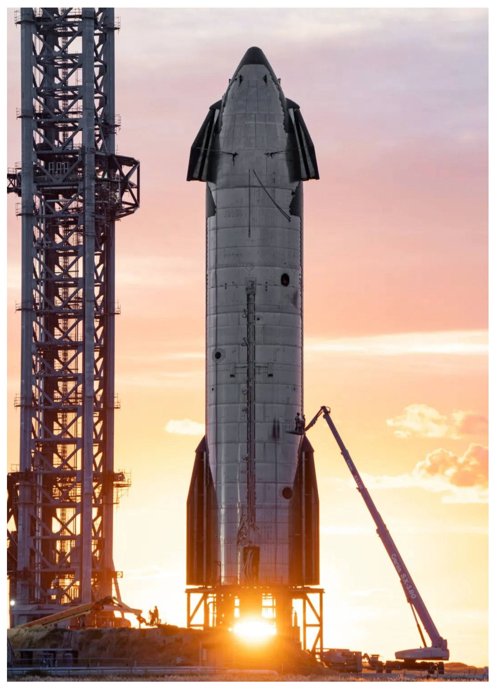
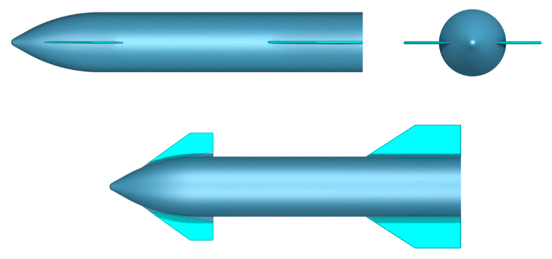
2. Aerodynamic Configuration of Starships
3. Performance Analysis
3.1. Analysis of Static Force and Moment Coefficients
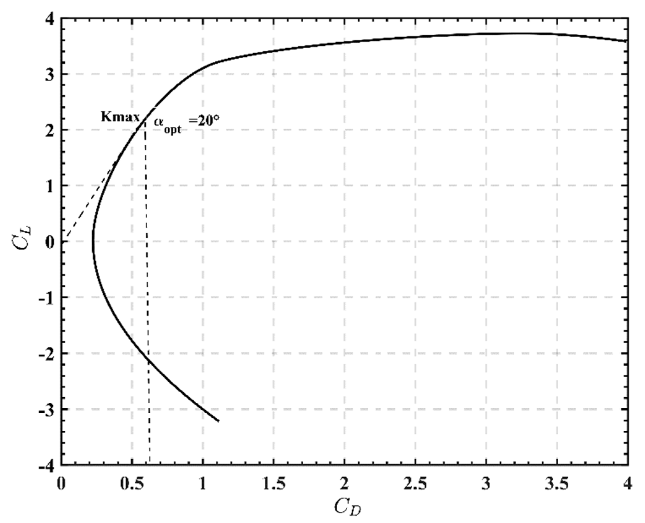
3.1.1. Analysis of Polar Curve and Lift-Drag Ratio
3.1.2. Analysis of Longitudinal Forces and Moments
- (1)
- The lift coefficient increases with the increase in the angle of attack when , and decreases with the increase in the angle of attack when . is the critical angle of attack.
- (2)
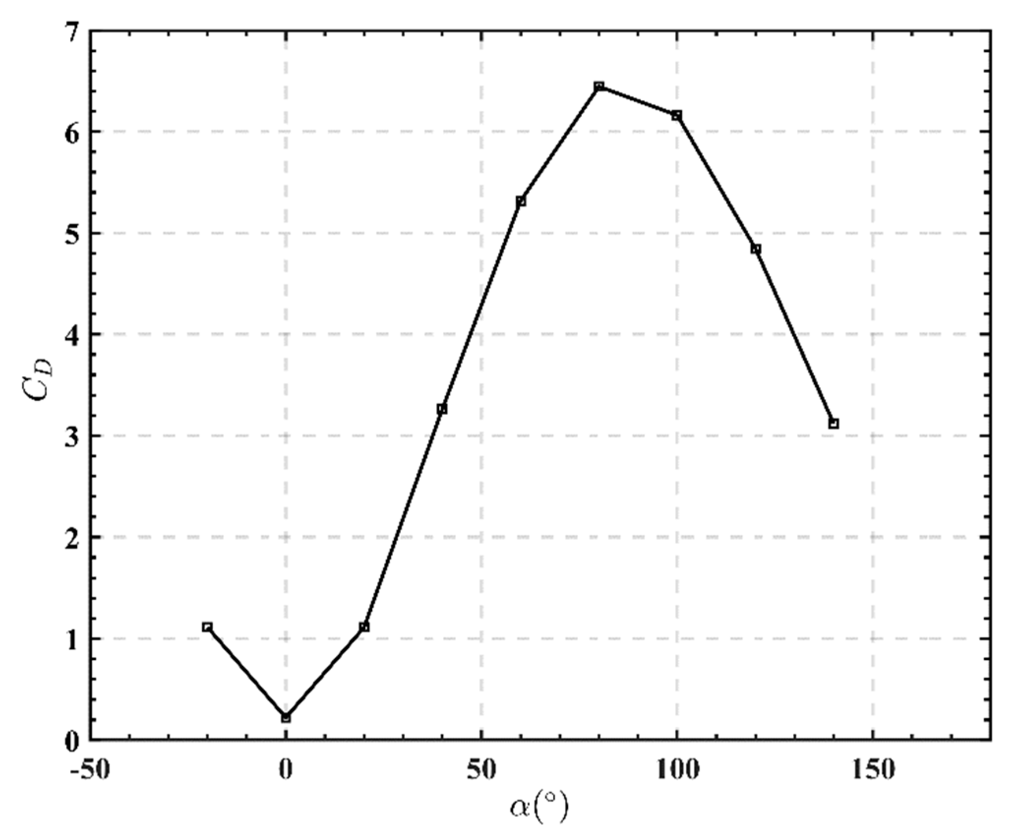
- When , the drag coefficient increases with the increase in the angle of attack; at and , the drag coefficient decreases with the increase in the angle of attack. When the angle of attack is 0, the drag coefficient is the minimum; when the angle of attack is 80°, the drag coefficient is the maximum. So when the starship returns, choose a horizontal descent to minimize the speed of descent with maximum resistance.
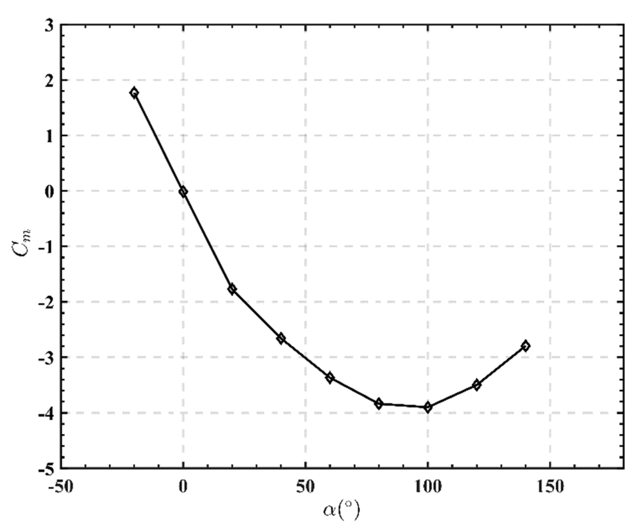
- (3)
- When , , a positive pitching moment is generated to make the starship raise its nose to reduce the angle of attack. Within the range of angle of attack , , a negative pitching moment is generated to make the starship bow its nose to reduce the angle of attack.
3.1.3. Lateral-Directional Force and Moment Analysis
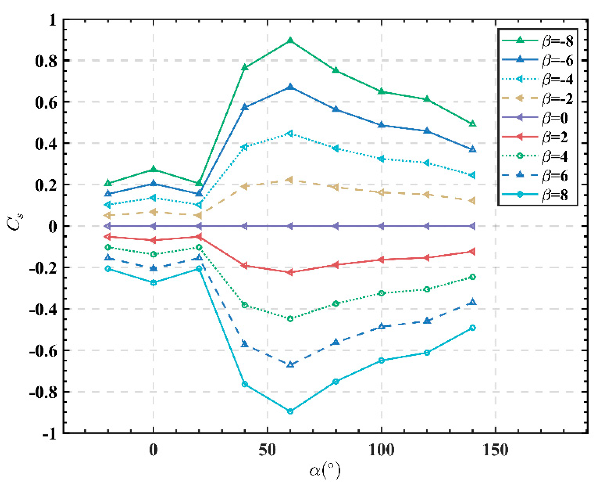
- (1)
- The variation of static lateral force coefficient with angle of attack is as follows: negative lateral force is generated if the side slip is positive, while if negative sideslip occurs, positive lateral force occurs.
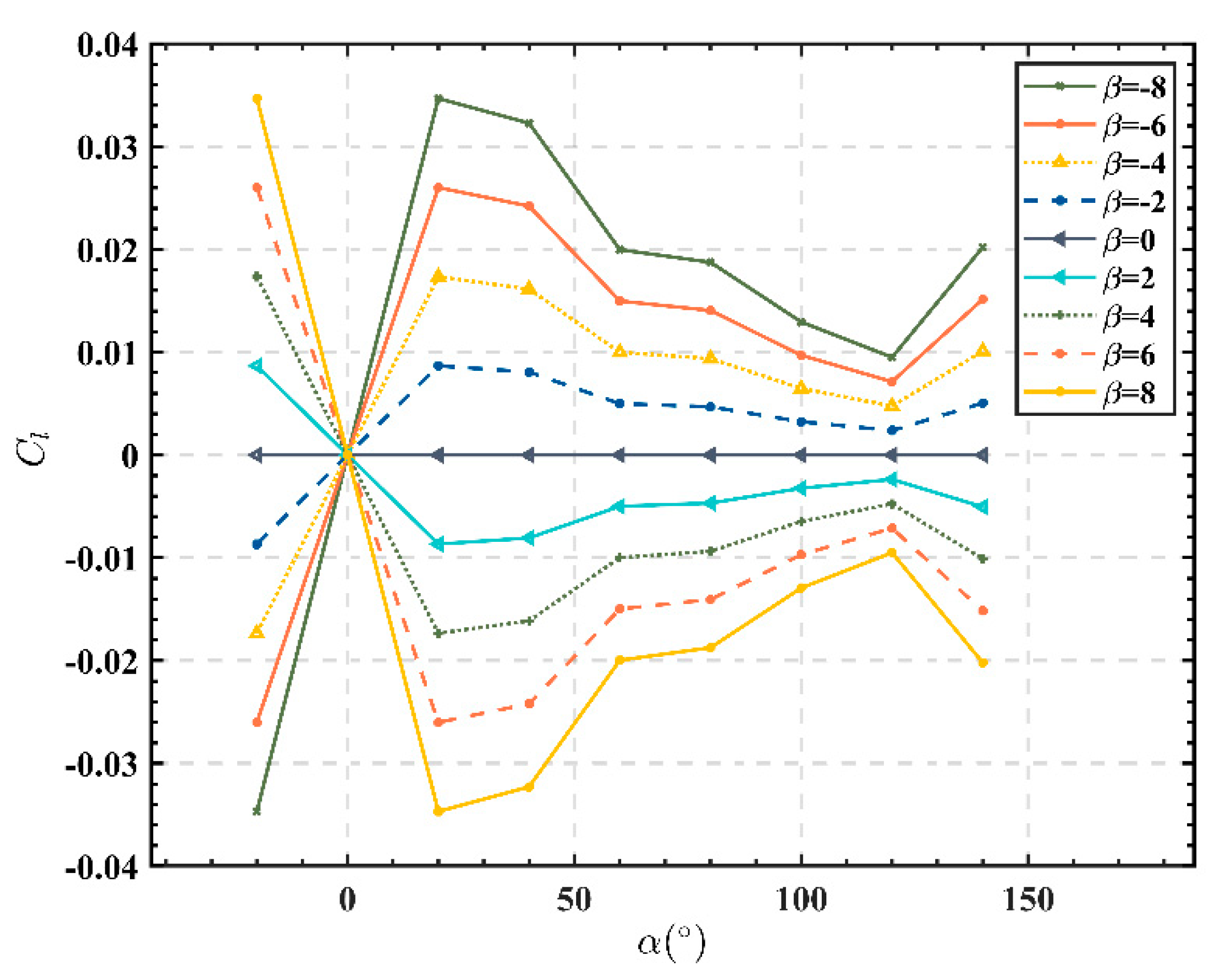
- (2)
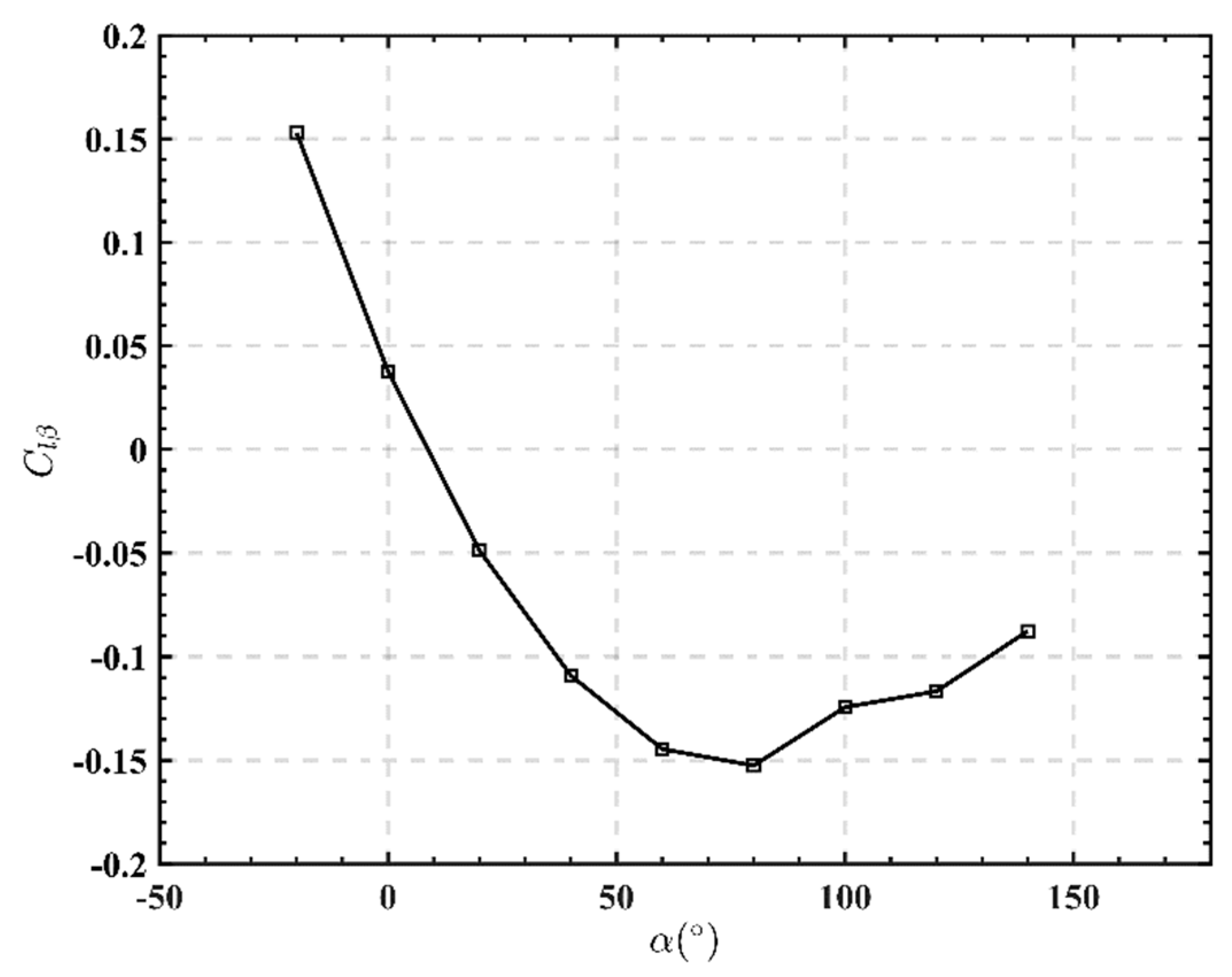
- When the positive side slip occurs, negative side force is generated, and then negative roll moment is generated, so the roll moment coefficient is negative; when negative sideslipping occurs, positive sideslipping force is generated, and then positive rolling moment is generated, so the rolling moment coefficient is positive.
- (3)
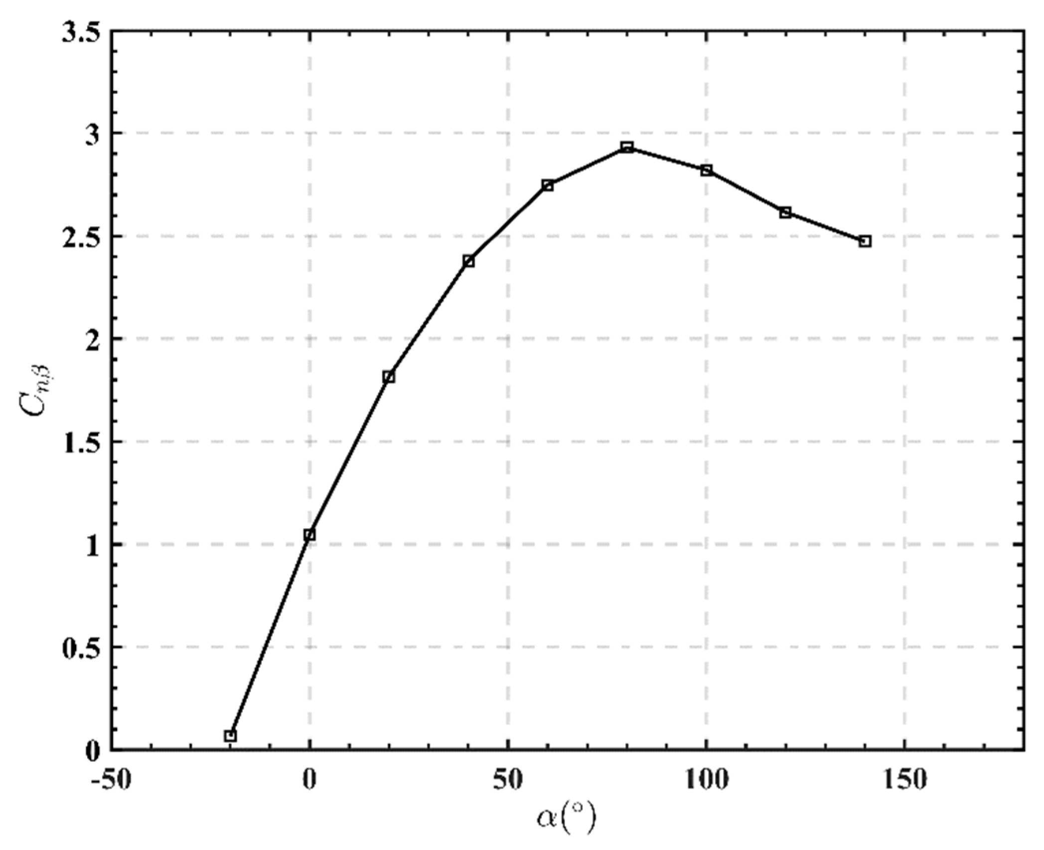
- When positive sideslip occurs, yaw moment coefficient is positive; when negative sideslip occurs, yaw moment coefficient is negative.
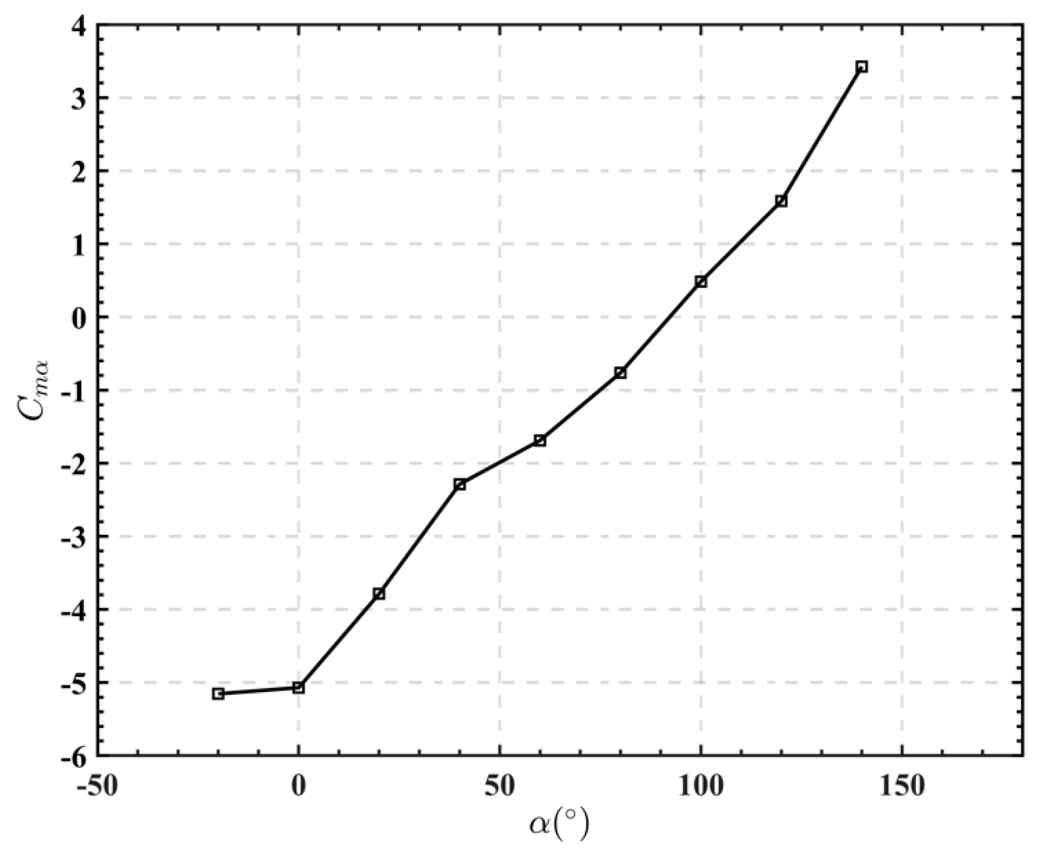
3.1.4. Static Stability Analysis
4. Analysis of Dynamic Characteristics
4.1. Analysis of Dynamic Derivatives
- (1)
- When a starship raises its head and generates a positive pitch angular rate, , a starship will also generate a negative pitch moment to prevent it from rotating upwards. Therefore, in Figure 13, within the angle of attack , the pitch damping derivatives are all negative, preventing the starship from rotating. When , the pitching damping is positive. This is because under a large angle of attack, because the air flow is in chaos, the polarity of the roll moment changes. As a result, during the horizontal descent in the returning stage, the largest angle of attack of the starships is 90° according to the analysis of its movement mode and path, so within its range of angle of attack during its movement process, its pitch damping derivative is negative all the time, which conforms to the actual flight characteristics.
- (2)
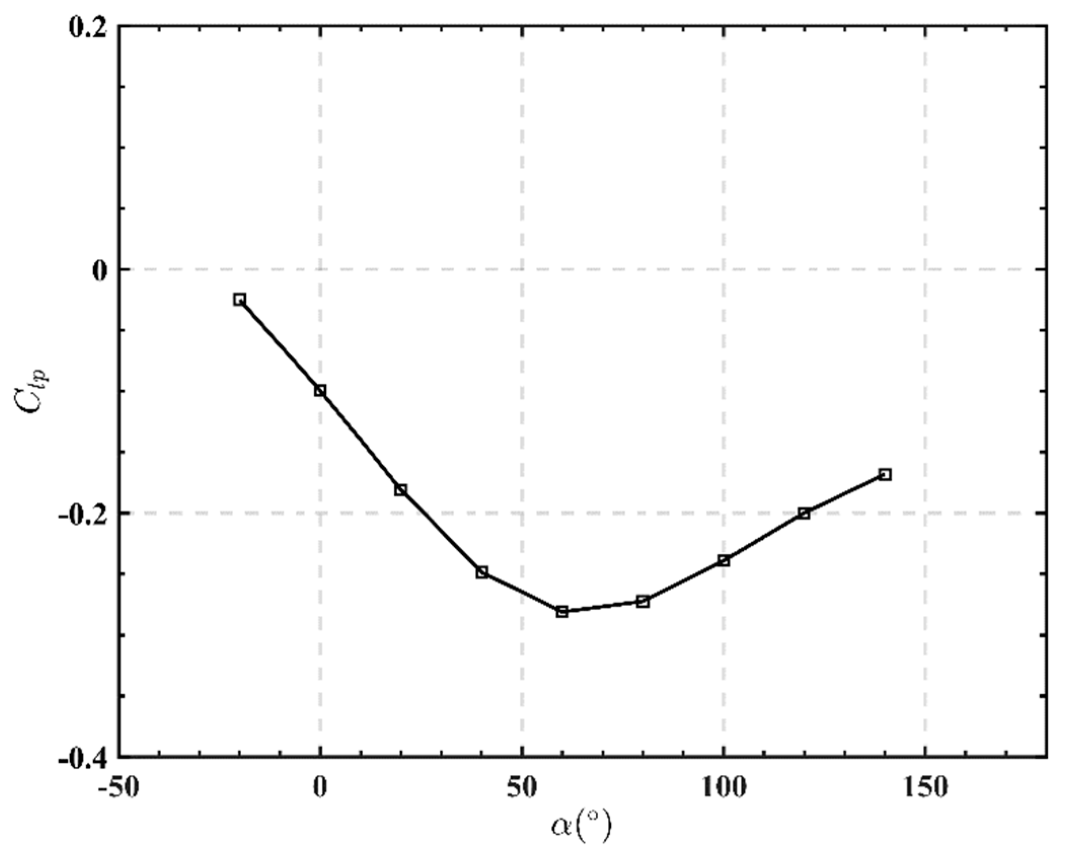
- If the starship rolls to the right, , the left and right rear wings are asymmetrically deflecting at this time, and a negative roll moment will be generated, which will hinder the roll. Within the whole range of angle of attack, the negative roll moment derivative is exactly caused by the roll angular rate, so the roll damping derivative is consistent with the actual flight characteristics.
- (3)
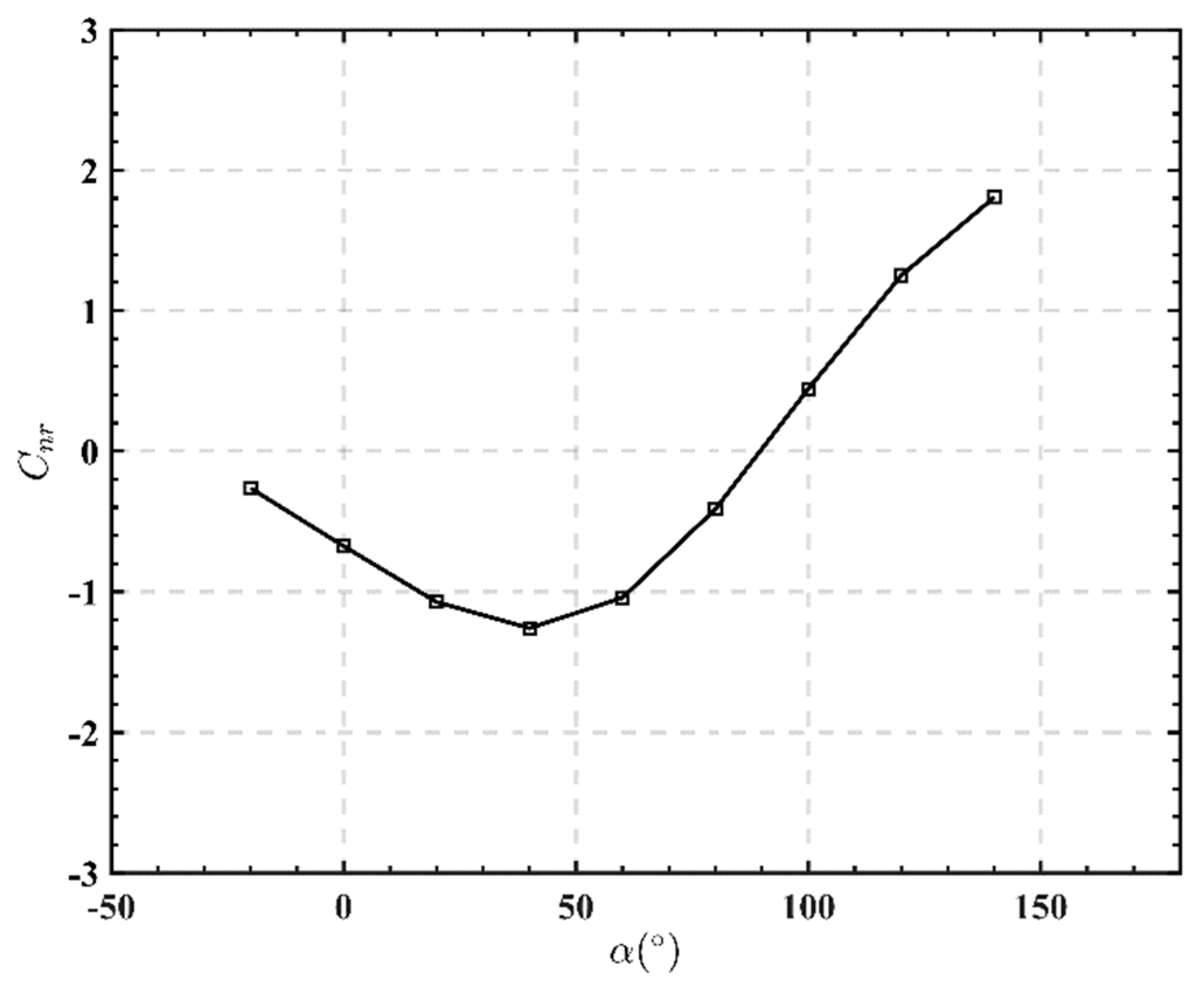
- The yaw damping derivative is negative in the range of angle of attack , but positive in the range of , which promotes the yaw of the starship. Therefore, this phenomenon is easy to cause the risk of excessive yaw in the recovery stage. According to the analysis, the yaw damping derivative conforms to the actual flight characteristics in the range of a small angle of attack, but in the process of a large angle of attack, it is underdamped.
4.2. Analysis of Manipulativeness Derivative
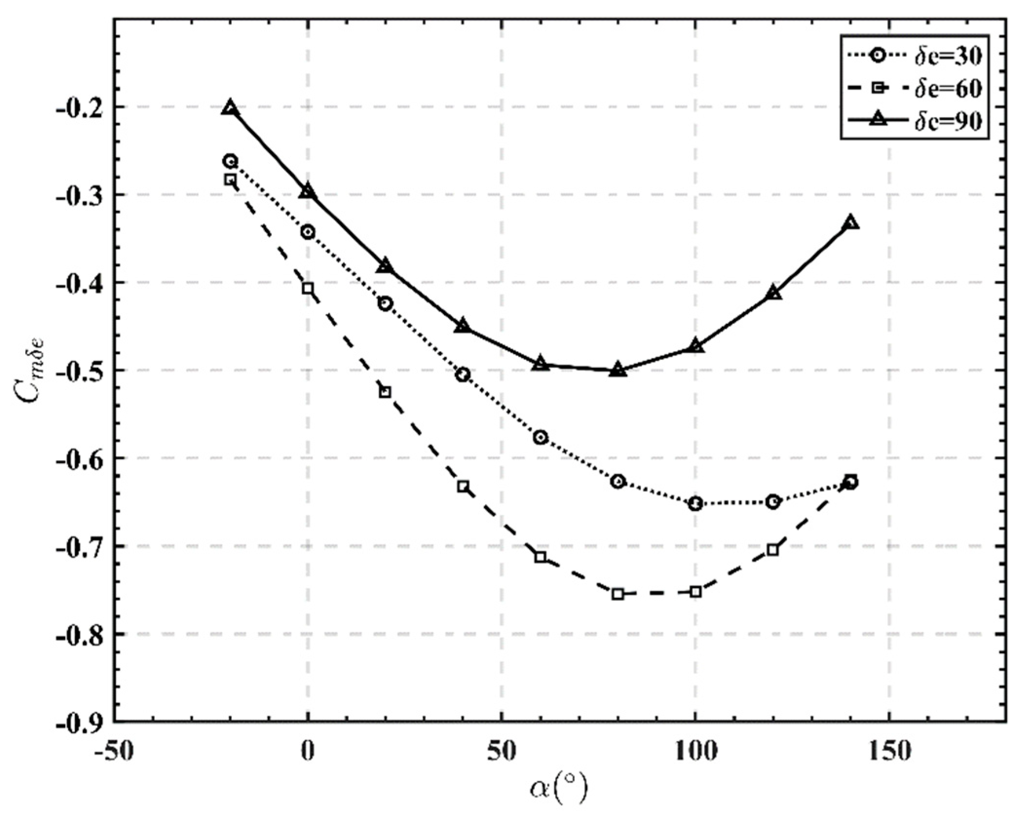
4.2.1. Pitching Manipulativeness Derivative
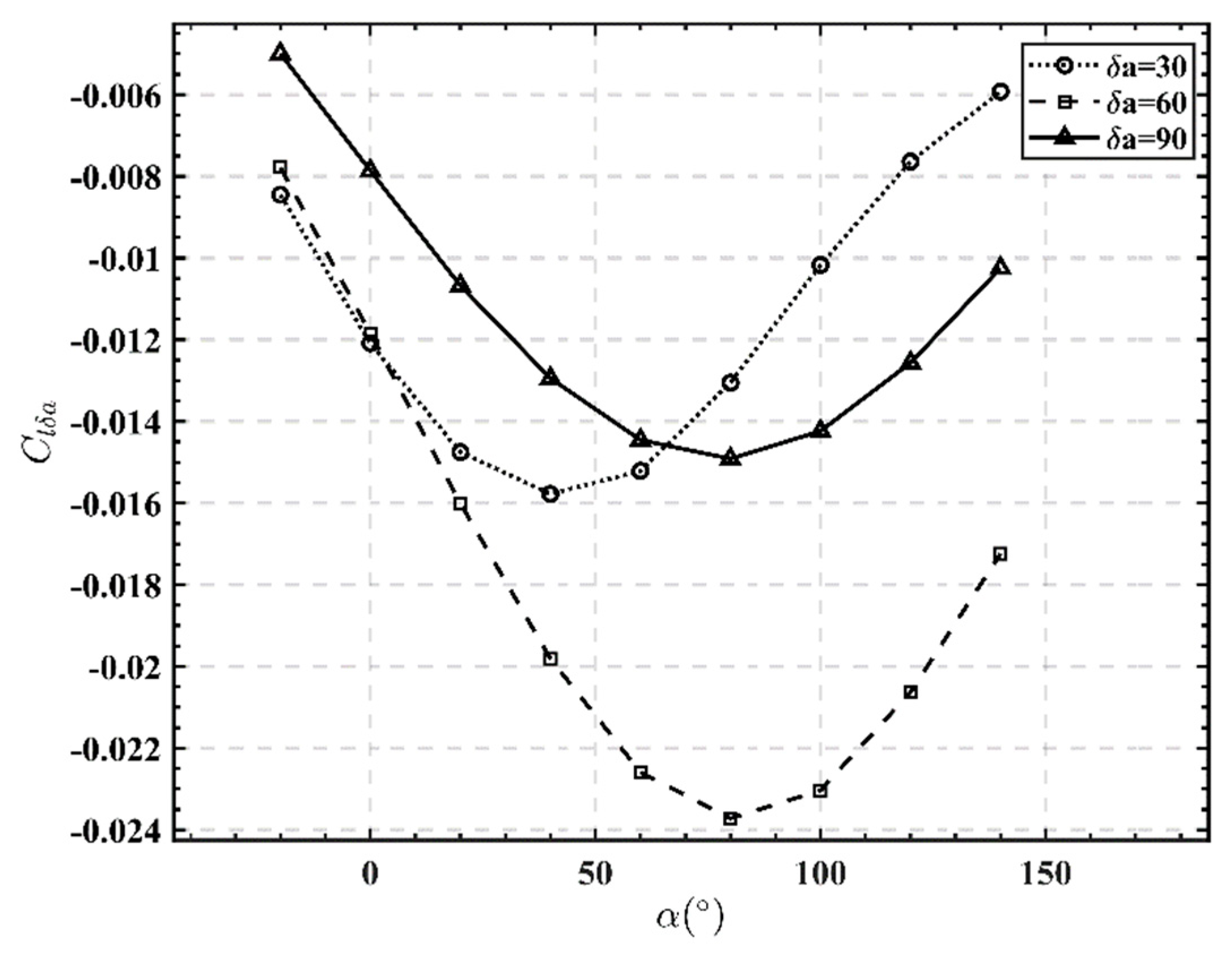
4.2.2. Rolling Manipulativeness Derivative
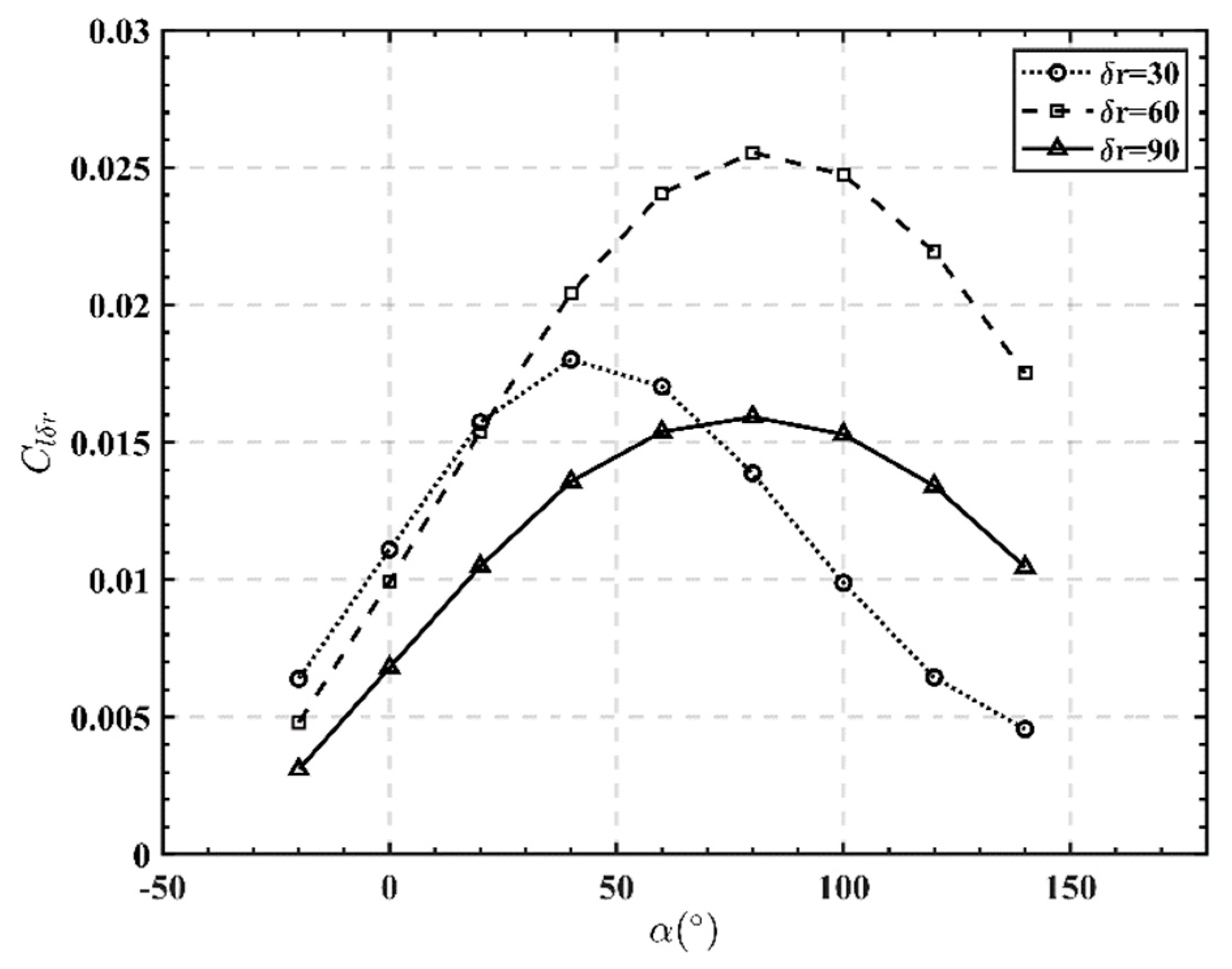
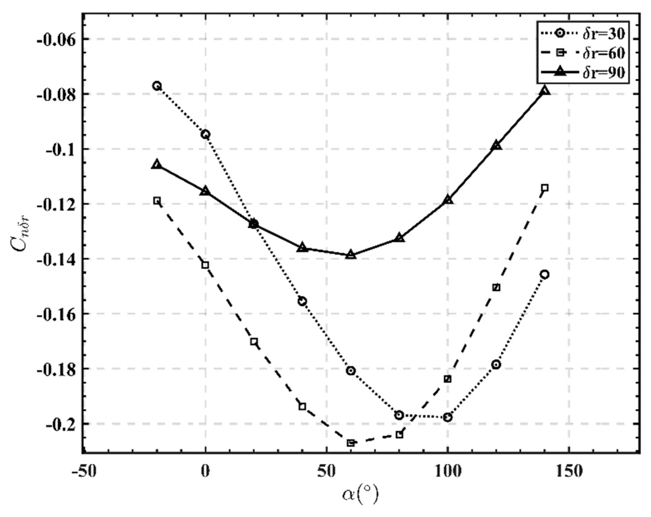
4.2.3. Yawing Manipulativeness Derivative
4.3. Analysis of Modal Characteristics and Flight Quality
4.3.1. Longitudinal Analysis
4.3.2. Lateral-Directional Analysis
4.4. Characteristics Analysis of the Ratio between Roll and Swing
5. Analysis Based on the Principle of Criteria
5.1. Criteria of the Margin of Longitudinal Static Stability
5.2. Criteria of Comprehensive Analysis of Lateral Direction
5.3. Analysis Criteria of Coordinated Control Deviation of Rudder-like and Aileron-like
5.4. Weissman Graph Criteria
6. Simulation Results of Nonlinear Open Loop
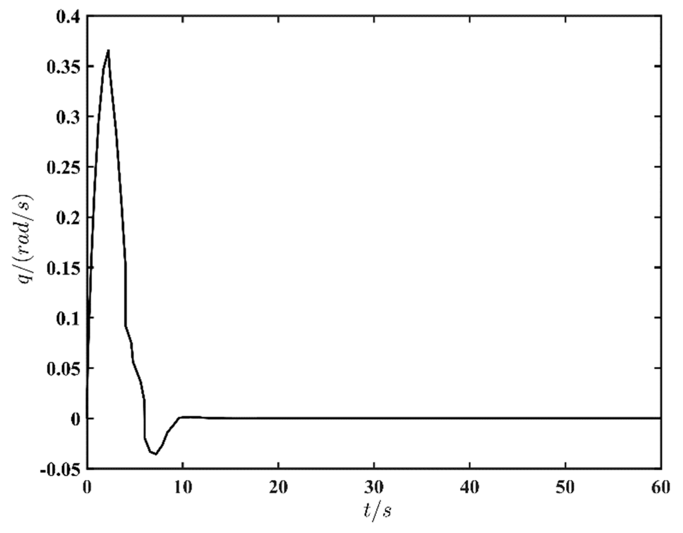
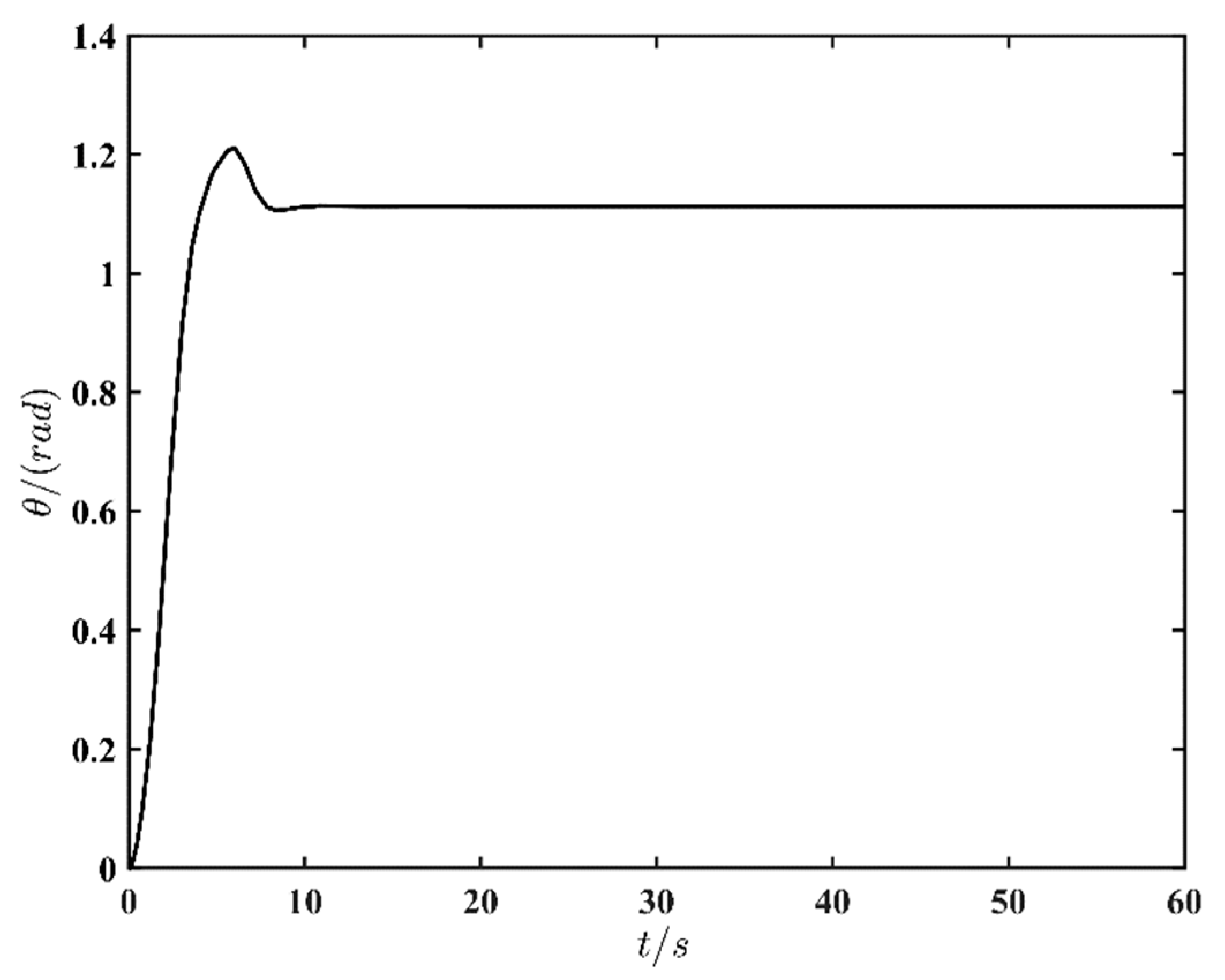
6.1. Longitudinal Simulation Results
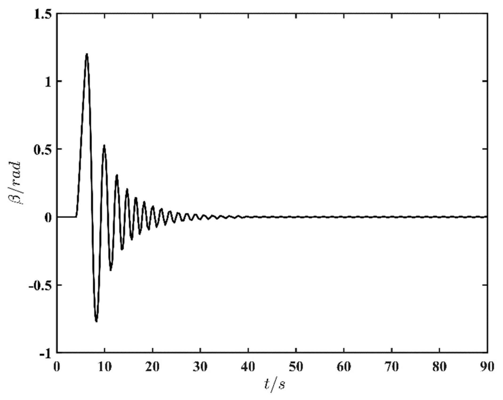
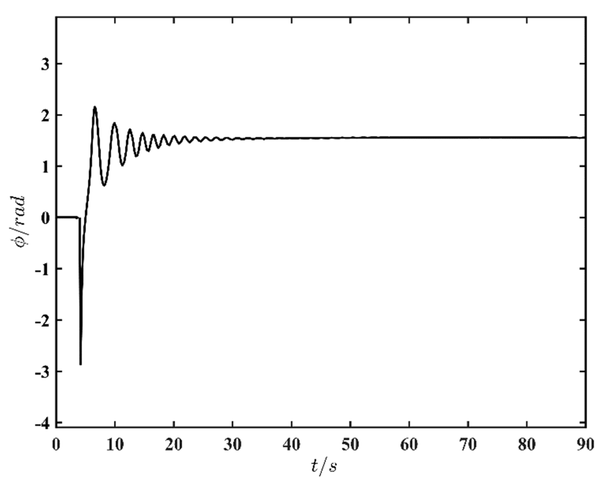
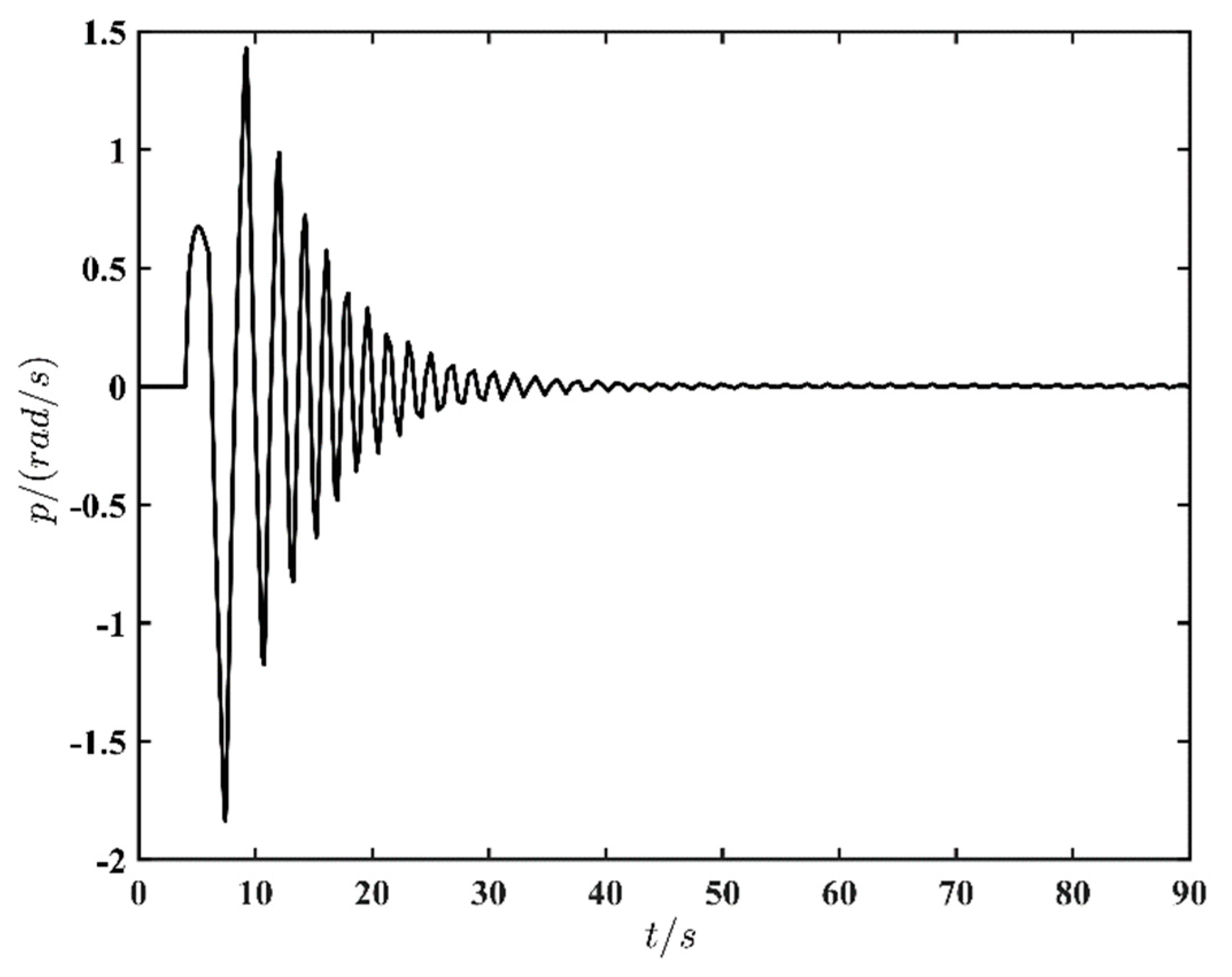
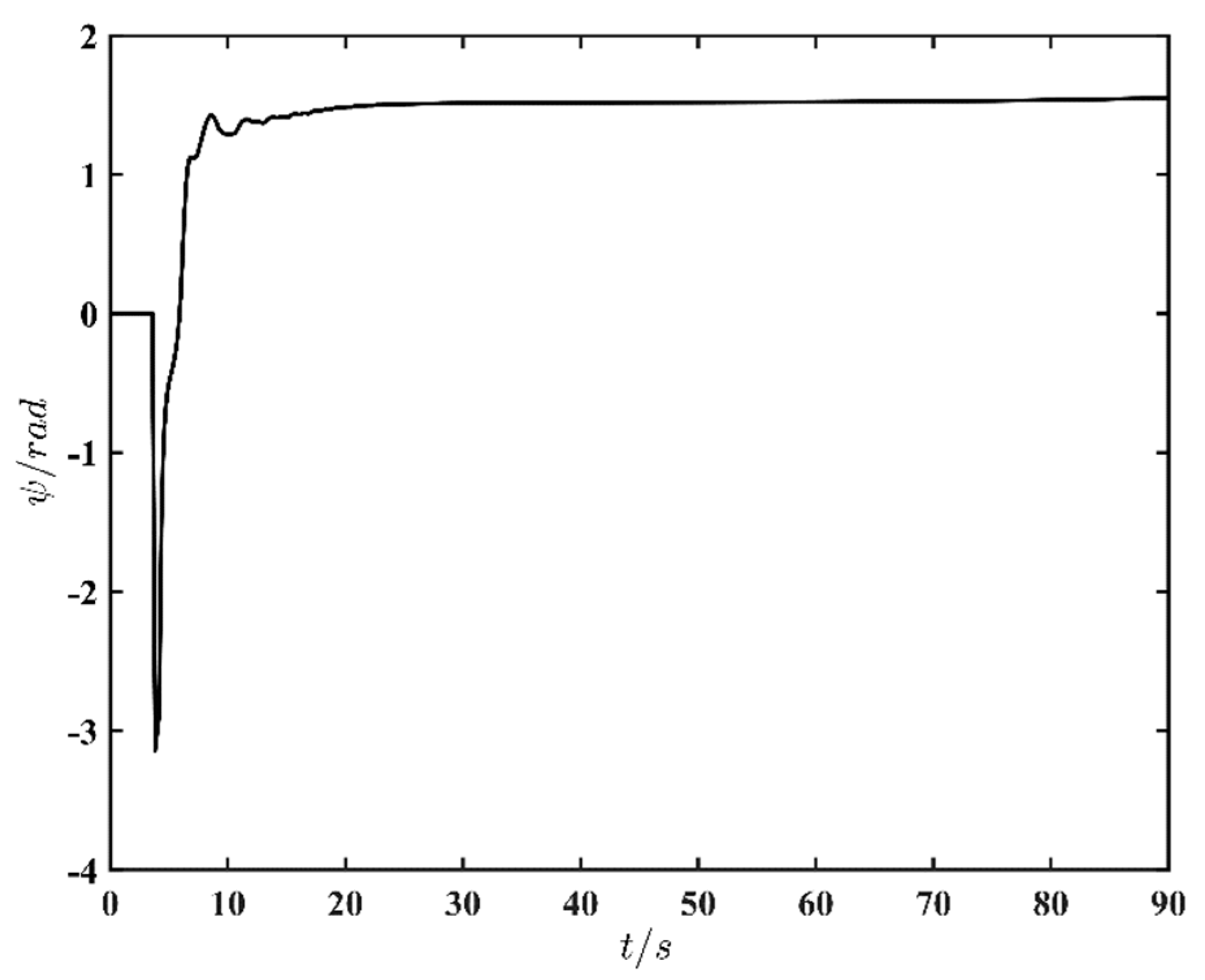
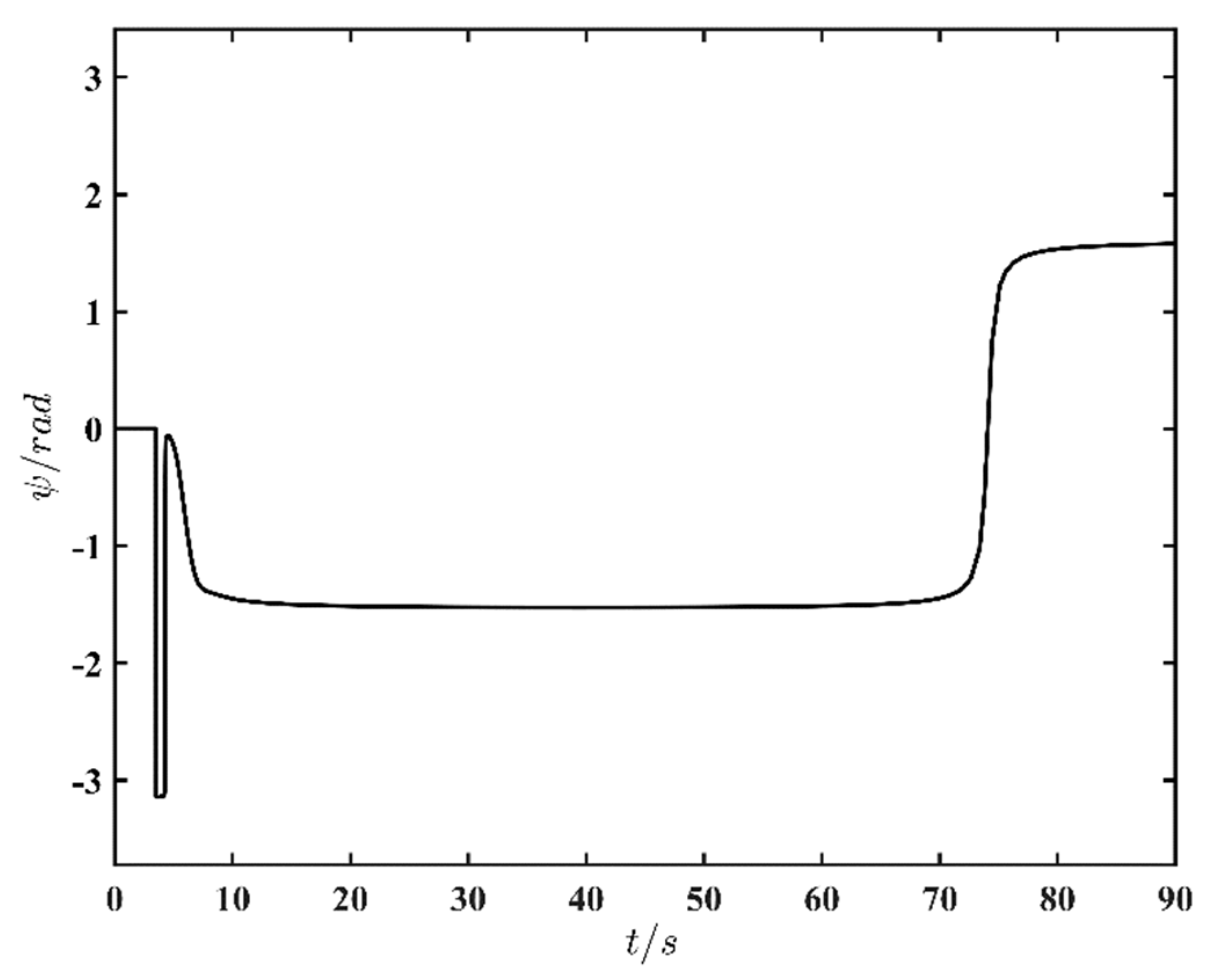
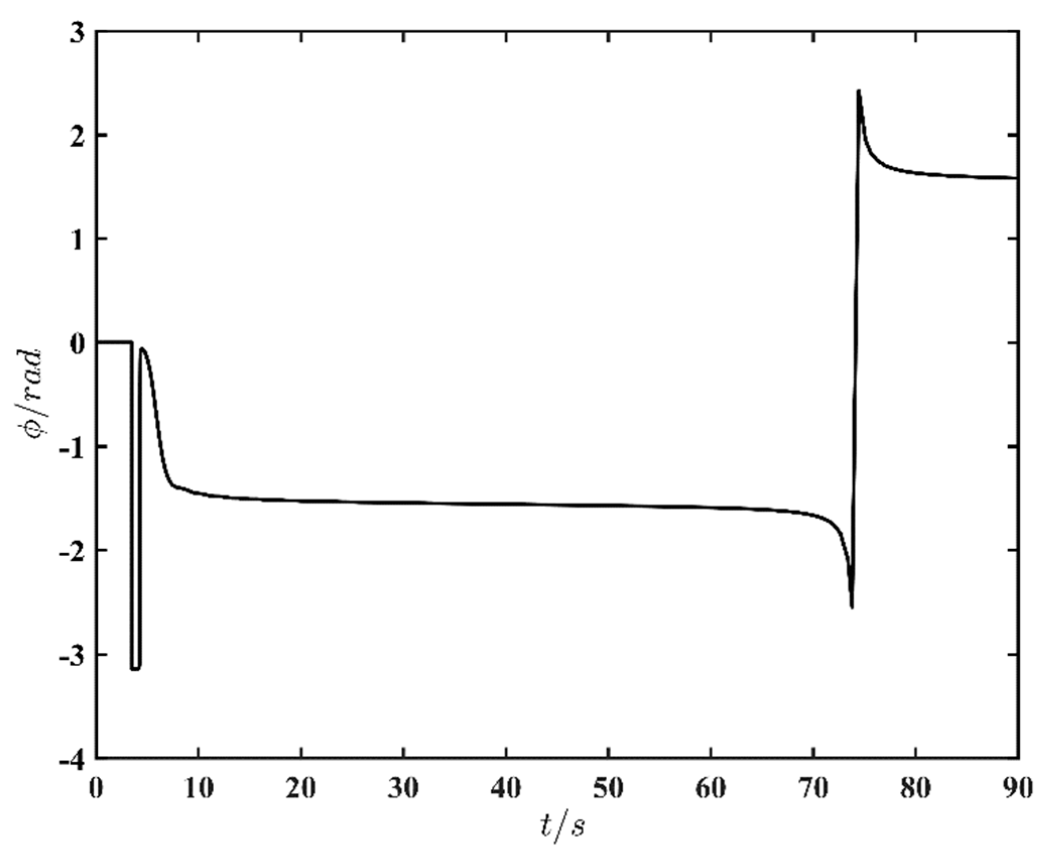
6.2. Lateral-Directional Simulation Results
7. Conclusions
Author Contributions
Funding
Institutional Review Board Statement
Informed Consent Statement
Data Availability Statement
Conflicts of Interest
Abbreviations
| RLV | Reusable Launch Vehicle |
| CFD | Computational Fluid Dynamics |
| LCDP | Lateral Control Departure Parameter |
| AoA | Angle of Attack |
References
- Britt, R.T.; Arthurs, T.D.; Jacobson, S.B. Aeroservoelastic analysis of the B-2 bomber. J. Aircr. 2000, 37, 745–752. [Google Scholar] [CrossRef]
- Jacobson, S.; Britt, R.; Freim, D.; Kelly, P. Residual pitch oscillation (rpo) flight test and analysis on the b-2 bomber. Ices J. Mar. Sci. 2003, 67, 1260–1271. [Google Scholar]
- Su, W.; Gao, Z.; Xia, L. Multiobjective optimization design of aerodynamic configuration constrained by stealth performance. Acta Aerodyn. Sin. 2006, 24, 137–140. [Google Scholar]
- Johnson, J.; Colbo, H. Space Shuttle main engine progress through the first flight. In Proceedings of the 17th Joint Propulsion Conference, Colorado Springs, CO, USA, 27–29 July 1981. [Google Scholar]
- Klotz, I. SpaceX Aims for Starship Crew Flights By 2023. Aerosp. Dly. Def. Rep. 2020, 272, 3. [Google Scholar]
- SpaceX Starship SN8 Takes Flight, 2020. Available online: https://www.spacex.com/updates/starship-sn8-takes-flight/index.html (accessed on 10 June 2022).
- SpaceX. Starship SN9 High-Altitude Flight Test, 2021. Available online: https://www.spacex.com/updates/starship-sn9-flight-test/index.html (accessed on 10 June 2022).
- SpaceX. Starship SN10 High-Altitude Flight Test, 2021. Available online: https://www.spacex.com/updates/starship-sn10-flight-test/index.html (accessed on 10 June 2022).
- SpaceX. Starship SN11 High-Altitude Flight Test, 2021. Available online: https://www.spacex.com/updates/starship-sn11-flight-test/index.html (accessed on 10 June 2022).
- SpaceX. StarShip SN15, 2021. Available online: https://www.spacex.com/updates/starship-sn15-flight-test/index.html (accessed on 10 June 2022).
- Klotz, I. Starship Hop on Hold Pending Demo-2. Aerosp. Dly. Def. Rep. 2020, 272, 2. [Google Scholar]
- Norris, G. SpaceX Plans Pacific Splashdown for First Starship Orbital Test. Aerosp. Dly. Def. Rep. 2021, 276, 6. [Google Scholar]
- Goman, M.G.; Khramtsovsky, A.V.; Kolesnikov, E.N. Evaluation of Aircraft Performance and Maneuverability by Computation of Attainable Equilibrium Sets. J. Guid. Control Dyn. 2008, 31, 329–339. [Google Scholar] [CrossRef]
- Klotz, I. Starship Lands, Then Bursts into Fireball. Aviat. Week Space Technol. 2021, 183, 30. [Google Scholar]
- Klotz, I. SpaceX Starship Prototype Passes Static Test Fire. Aerosp. Dly. Def. Rep. 2020, 272, 4. [Google Scholar]
- Palmer, C. SpaceX Starship Lands on Earth, but Manned Missions to Mars will Require More. Engineering 2021, 7, 1345–1347. [Google Scholar] [CrossRef]
- Owen, D.B. The starship. Commun. Stat.-Simul. Comput. 1988, 17, 315–323. [Google Scholar] [CrossRef]
- Klotz, I. Third Starship Prototype Lost During Cryogenic Tanking Test. Aerosp. Dly. Def. Rep. 2020, 272, 2. [Google Scholar]
- Norris, G. SpaceX Sticks Starship Landing After High-Altitude Flight Test. Aerosp. Dly. Def. Rep. 2021, 276, 1–2. [Google Scholar]
- Weiss, D. Creating Materials for the Starship. J. Br. Interplanet. Soc. (JBIS) 2015, 68, 211–213. [Google Scholar]
- Galea, P. Machine Learning and the Starship—A Match Made in Heaven. J. Br. Interplanet. Soc. (JBIS) 2012, 65, 278–282. [Google Scholar]
- Norris, G. SpaceX’s Star Hopper Verifies Raptor Performance for Starship. Aviat. Week Space Technol. 2019, 181, 28. [Google Scholar]
- Klotz, I. SpaceX Starship Crashes after High-Altitude Flight Test. Aerosp. Dly. Def. Rep. 2020, 274, 3. [Google Scholar]
- Seedhouse, E. Starship. In SpaceX; Springer: Cham, Switzerland, 2022; pp. 171–188. [Google Scholar]
- Klotz, I. SpaceX Prototype Starship Survives Low-Altitude Hop. Aerosp. Dly. Def. Rep. 2020, 273, 3. [Google Scholar]
- Hayes, C.; Starship Troopers. ACM SIGGRAPH 98 Conference Abstracts and Applications. 1998. p. 311. Available online: https://dl.acm.org/doi/pdf/10.1145/280953.282447 (accessed on 10 June 2022).
- Wang, Z.; Mao, S.; Gong, Z. Energy Efficiency Enhanced Landing Strategy for Manned eVTOLs Using L1 Adaptive Control. Symmetry 2021, 13, 2125. [Google Scholar] [CrossRef]
- Zhang, Y.J.; Zuo, G. Numerical simulation on aerodynamic characteristics of new type control surface of Starship. Acta Aeronaut. Astronaut. Sin. 2021, 42, 624058. (In Chinese) [Google Scholar]
- Parsons, D.G.; Levin, D.E.; Panteny, D.J.; Wilson, P.N.; Rask, M.R.; Morris, B.L. F-35 STOVL Performance Requirements Verification. In The F-35 Lightning II: From Concept to Cockpit; American Institute of Aeronautics and Astronautics: Reston, VA, USA, 2022; pp. 641–680. [Google Scholar]
- Walker, G.; Allen, D. X-35B STOVL Flight Control Law Design and Flying Qualities. In Proceedings of the 2002 Biennial International Powered Lift 641 Conference and Exhibit, Williamsburg, VA, USA, 5–7 November 2002; pp. 1–13. [Google Scholar]
- Osder, S.; Caldwell, D. Design and robustness issues for highly augmented helicopter controls. J. Guid. Control Dyn. 1992, 15, 1375–1380. [Google Scholar] [CrossRef]
- Carter, J.; Stoliker, P. Flying quality analysis of a JAS 39 Gripen ministick controller in an F/A-18 aircraft. In Proceedings of the AIAA Guidance, Navigation, and Control Conference and Exhibit, Dever, CO, USA, 14–17 August 2000; pp. 1–20. [Google Scholar]
- Yang, X.; Fan, Y.; Zhu, J. Transition Flight Control of Two Vertical/Short Takeoff and Landing Aircraft. J. Guid. Control Dyn. 2008, 31, 371–385. [Google Scholar]
- Gerontakos, P.; Lee, T. Trailing-edge flap control of dynamic pitching moment. AIAA J. 2007, 45, 1688–1694. [Google Scholar] [CrossRef]
- Andrews, J.; Andrews, D. Designing reusable launch vehicles for future space markets. In Proceedings of the AIAA Space 2001 Conference and Exposition, Albuquerque, NM, USA, 28–30 August 2001; p. 4544. [Google Scholar]
- Zhong, Y.; Liu, D.; Wang, C. Research progress of key technologies for typical reusable launcher vehicles. In IOP Conference Series: Materials Science and Engineering; IOP Publishing: Bristol, UK, 2018; Volume 449, p. 012008. [Google Scholar]


| B747 | Flying Aircraft | Starship |
|---|---|---|
| −0.4650 + 1.2456i | −1.6 | −1.05 + 1.99i |
| −0.4650–1.2456i | 0.7 | −1.05–1.99i |
| −0.0097 + 0.0445i | −0.01 + 0.12i | −5.98 × 10⁻¹³ |
| −0.0097–0.0445i | −0.01–0.12i | −0.0185 |
| Mode | |||||
|---|---|---|---|---|---|
| Third mode | 37.46 | ---- | 0 | 1 | 0.0185 |
| Short mode | 0.66 | 3.157 | 0.209 | 0.4667 | 2.25 |
| Estimation long-period | 11.55 | 25.671 | 0.4499 | 0.2381 | 0.252 |
| Mode | Level of Flight Quality | Type of Aircraft | Maximum of | Minimum of |
|---|---|---|---|---|
| Short mode | 1 | C | 1.30 | 0.35 |
| 2 | 2.00 | 0.25 | ||
| 3 | ----- | 0.15 | ||
| Long mode | 1 | C | ||
| 2 | ||||
| 3 | ||||
| B747 | Flying Aircraft | Starship |
|---|---|---|
| −0.1507 + 0.9431i | 0.025 + 0.35i | 0.175 + 0.195i |
| −0.1507–0.9431i | 0.025–0.35i | 0.175–0.195i |
| −0.3725 | −2.0000 | −0.336 |
| 0.0058 | 0.0006 | −0.00444 |
| Parameters | Rolling Time Constant | Spiral Amplitude Doubling Time | Natural Frequency of Dutch Roll | Damping Ratio of Dutch Roll | |
|---|---|---|---|---|---|
| Value | 2.98 | 225 | 0.669 | 0.261 | 0.175 |
| Parameters | Standards of Flight Quality | Type of Flight Stage | Type of Aircraft | Maximum of | Minimum of | Minimum of | Minimum of | Minimum of |
|---|---|---|---|---|---|---|---|---|
| Value | I | C | II III | 1.4 | 20 | 0.4 | 0.08 | 0.15 |
| II | 3.0 | 12 | 0.4 | 0.02 | 0.05 | |||
| III | 10 | 4 | 0.4 | 0.02 | --- |
Publisher’s Note: MDPI stays neutral with regard to jurisdictional claims in published maps and institutional affiliations. |
© 2022 by the authors. Licensee MDPI, Basel, Switzerland. This article is an open access article distributed under the terms and conditions of the Creative Commons Attribution (CC BY) license (https://creativecommons.org/licenses/by/4.0/).
Share and Cite
Gong, Z.; Wang, Z.; Yang, C.; Li, Z.; Dai, M.; Zhang, C. Performance Analysis on the Small-Scale Reusable Launch Vehicle. Symmetry 2022, 14, 1862. https://doi.org/10.3390/sym14091862
Gong Z, Wang Z, Yang C, Li Z, Dai M, Zhang C. Performance Analysis on the Small-Scale Reusable Launch Vehicle. Symmetry. 2022; 14(9):1862. https://doi.org/10.3390/sym14091862
Chicago/Turabian StyleGong, Zheng, Zian Wang, Chengchuan Yang, Zhengxue Li, Mingzhe Dai, and Chengxi Zhang. 2022. "Performance Analysis on the Small-Scale Reusable Launch Vehicle" Symmetry 14, no. 9: 1862. https://doi.org/10.3390/sym14091862
APA StyleGong, Z., Wang, Z., Yang, C., Li, Z., Dai, M., & Zhang, C. (2022). Performance Analysis on the Small-Scale Reusable Launch Vehicle. Symmetry, 14(9), 1862. https://doi.org/10.3390/sym14091862