1. Introduction
With the rapid development of computer networks and multimedia technology, digital information is transmitted on the network environment more conveniently. However, such digital information faces many risks related to security issues. To solve these issues, many cryptography techniques i.e., DES, AES and RSA [
1], have been proposed. Cryptography techniques encrypt the digital information from plaintext to cipher text, leading to an increase in attention from attackers. Another promising solution is data-hiding techniques that conceal the confidential data into cover data, i.e., text, images, audio.... In the data-hiding schemes, imperceptibility must be considered. This means that the attacker cannot detect the secret information in the marked data. The data-hiding schemes can be classified into two different categories, i.e., irreversible and reversible data-hiding schemes. For an irreversible data-hiding scheme, only secret data can be extracted, while the restoration of the cover data is unavailable. In contrast, a reversible data-hiding (RDH) scheme can extract the secret data and recover the original cover images in the extracting process. In recent years, RDH schemes have received much attention from the research community [
2,
3,
4,
5]. RDH schemes are suitable in some sensitive scenarios, such as military, medical and forensic fields, where any permanent distortion is unacceptable, and the exact recovery of the original cover data is required. RDH schemes for digital images can be classified into three different domains, including: frequency, compression, and spatial domains [
6,
7,
8,
9,
10,
11,
12,
13,
14,
15,
16,
17,
18].
In the frequency domain [
6,
7,
8,
9], the cover image is first transformed into frequency coefficients via various transform functions, i.e., discrete Fourier transform (DFT), discrete cosine transform (DCT), and discrete wavelet transform (DWT). In 2018, Vo et al. [
6] proposed a 2D HS-based RDH scheme. In their scheme, the suitable quantized DCT (QDCT) coefficients are determined for embedding the secret data. As a result, their embedding capacity and image quality are improved further. Later on, Vo et al. proposed another algorithm [
7] in the frequency domain. In [
7], they applied both DCT and singular-value decomposition (SVD) mechanisms to embed watermarks for digital image copyright. Compared with RDH schemes in the spatial domain, RDH schemes in the frequency domain are more complex in terms of the execution. However, the RDH schemes in the frequency domain maintain greater robustness against various malicious attacks. In the compression domain, the cover images are compressed to preserve the room for containing the secret data. Many RDH solutions for compressed images have been proposed in [
10,
11,
12,
13]. These schemes obtained a high embedding capacity. However, they offered an increase in file size when containing the secret data.
In the spatial domain, the RDH schemes can be divided into two categories: histogram-shifting (HS) based and difference-expansion (DE) based. In the HS-based category, in 2006, Ni et al. proposed a HS-based RDH scheme [
15]. Ni et al.’s scheme embedded the secret bits by modifying the pairs of peak point and zero point. In the HS-based RDH technique, the embedding capacity depends on the height of the peak point bin of the histogram. Therefore, in order to increase the embedding capacity, many algorithms [
16,
17,
18] have tried to generate a sharper histogram. The HS-based RDH techniques obtained a high embedding capacity for smooth images. However, they suffered a low embedding capacity for texture images. In the DE-based category, the attention of several researchers was attracted [
14,
19,
20,
21,
22,
23,
24,
25,
26,
27,
28]. In 2003, Tian [
14] proposed the first DE-based scheme. In [
14], two adjacent pixels in the cover image are grouped into a pair. Then, the difference in pixels in the pair is computed and expanded to carry one secret bit. Therefore, the maximum embedding capacity in [
14] can be obtained up to 0.5 bpp. To increase the embedding capacity, Alattar [
19] proposed a new DE-based RDH scheme. Instead of using two adjacent pixels as was done in [
14], in Alattar’s scheme the cover image is divided into non-overlapping blocks with a size of 2 × 2 pixels. With four pixels in each block, up to three difference values are determined and expanded for embedding three secret bits. As a result, the higher embedding capacity is obtained in Alattar’s scheme, up to 0.75 bpp. However, by doing so, the original pixels will be twice changed for containing the secret data, causing much distortion in the stego-images. To overcome this shortcoming, several improved solutions were proposed in [
20,
21,
22,
23,
24,
25]. To further improve the performance of Alattar’s scheme, Liu et al. [
20] proposed a novel DE-based RDH scheme by using a reduced difference expansion (RDE) algorithm. In their scheme, to minimum the modification, the difference value between pixels of the pair is reduced before embedding the secret bits. Liu et al.’s scheme obtained the better quality of stego-images. Later on, to improve embedding capacity further, a hybrid RDH scheme based on DE and HS techniques was proposed by Kukreja et al. [
25]. In Kukreja et al.’s scheme, the cover image is divided into non-overlapping blocks with the size of a × b pixels. In each block, a × (b−1) difference values are calculated from a × b pixels of the block. Then, the histogram of these difference values is constructed for embedding the secret data by HS technique. According to the properties of 2 × 2 blocks, several RDE-based RDH schemes are proposed in [
21,
22,
23,
24]. In such schemes, different techniques are used to determine the suitable difference values for embedding data. The image blocks are divided into three different groups, i.e., (1) expandable, (2) changeable, and (3) unchangeable groups. To avoid overflow/underflow problems, only expandable and changeable groups are modified to carry secret bits. For the blocks belonging to the expandable group, the difference values, larger than one, are reduced to embed the secret data by using the RDE technique. For the blocks belonging to the changeable group, the original difference values are directly modified to embed secret data by the DE algorithm. By applying the RDE technique, these RDE-based RDH schemes [
20,
21,
22,
23,
24,
25,
26,
27,
28] achieved the better image quality of stego-images. However, they offered a low embedding capacity, because each pair of pixels is used to carry only one secret bit.
In the DE-based and RDE-based RDH schemes, only one secret bit is embedded into the difference of the pixel pair. In this paper, to improve the embedding capacity while maintaining the good image quality, a novel RDH scheme is proposed by using the ERDE technique. In the proposed scheme, two determined thresholds are used to classify difference values and to determine how these difference values are to be processed to maintain the image quality. Then, more secret bits are embedded into small difference values. For other difference values, they are reduced. Further, to increase the embedding capacity, small, reduced difference values are used to conceal the secret bits while the others are kept unchanged to guarantee the good image quality of the stego-images.
The rest of the paper is organized as follows; we briefly introduce previous related works in
Section 2. Then,
Section 3 elaborates the proposed scheme. To evaluate the performance of the proposed scheme, experimental results are given in
Section 4. Our conclusions are drawn in
Section 5.
3. Proposed Algorithm
In this section, our DE-based RDH algorithm is presented in detail. To improve the embedding capacity and the image quality, the two following techniques are applied in the proposed scheme.
- (1)
Secret message encoding: For fair comparison, the generated secret data, based on the symmetry concept, means the secret bits should be random and the distribution of the secret data remains uniform. Then, two adjacent bits of the secret data are converted into decimal form.
- (2)
The ERDE technique: Each original difference value of the pixel pair is reduced before expanding for data embedding.
In the proposed scheme, the cover image is divided into 2 × 2 non-overlapping blocks. In each of these blocks, the smallest pixel is used as a base point to compute the difference values (DV). Next, the determined threshold
is used to classify which DV values are to be embedded or to be reduced. If the DV values are larger than
, the ERDE technique is used to narrow the DV value for embedding data. Moreover, to maintain the tradeoff between the embedding capacity and the image quality in the data-embedding process, the second threshold
is used. If DVs of a block after reducing are smaller than
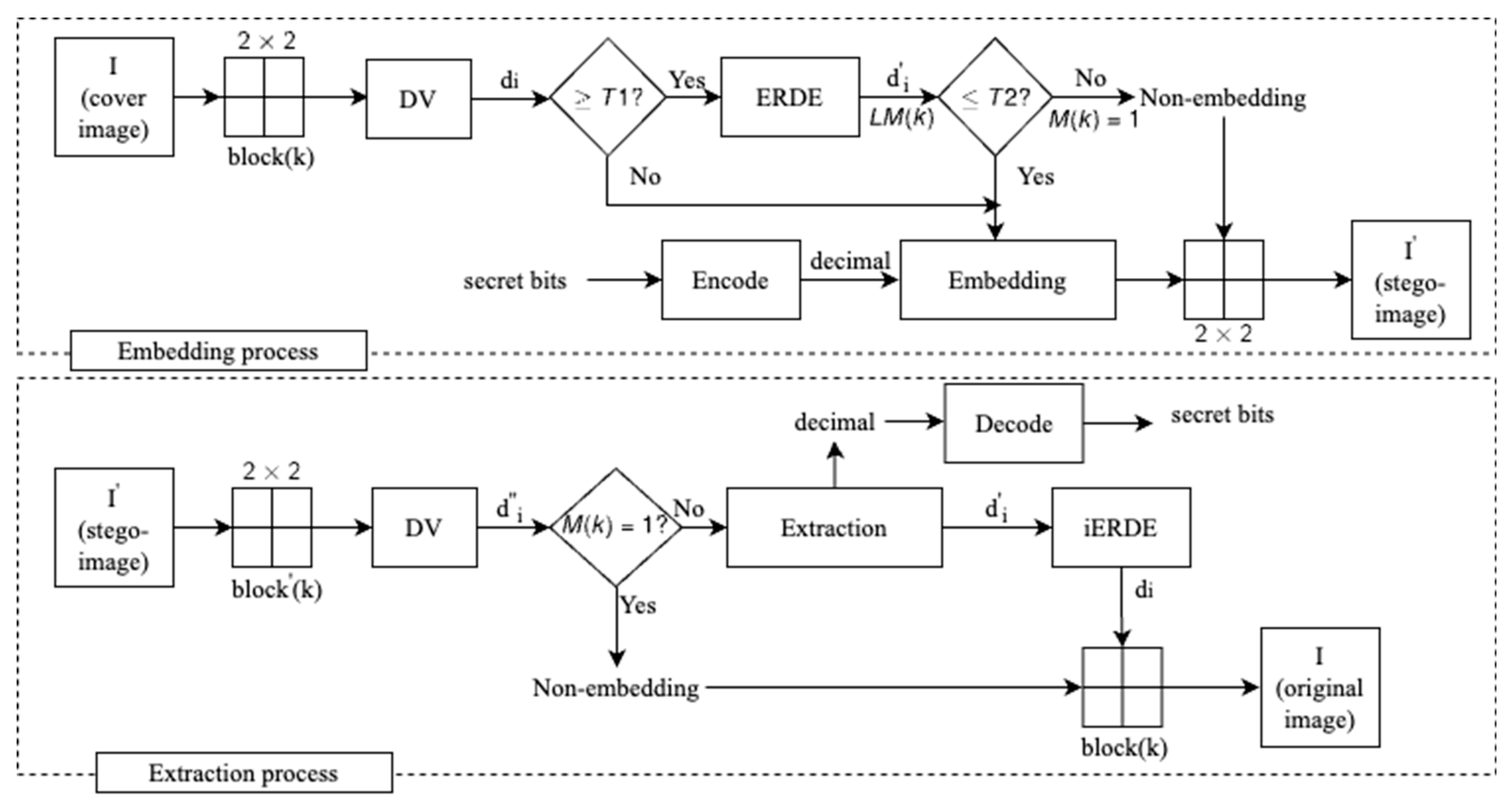
, they are used for embedding secret bits. Otherwise, they are kept unchanged. The flowchart of our proposed scheme is presented in
Figure 1.
The data embedding and extraction procedure are described in detail as follows:
3.1. The Data Embedding Procedure
To embed the message into the cover image , the eight following steps are used in the data-embedding algorithm:
Step 1. Encode the message into an integer sequence B with elements, . Two adjacent bits in S is converted into the integer value ; therefore, .
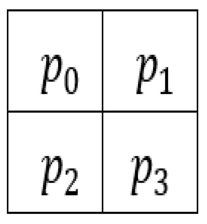
Step 2. Divide the cover image
into quad blocks of the size of 2 × 2 as shown in
Figure 2. Each block is then converted into a vector, which is given as
.
Step 3. Determine the minimum value by sorting the vector in assending order. Obtain the vector , with
Step 4. Compute the difference value
by using Equation (5).
where
and
are four pixels of the quad block, and
is the difference between two pixels.
Step 5. Enhance the reduced difference value: A threshold
is given to determine whether
should be reduced or not. In the proposed scheme, if the difference is less than a given threshold
, we use the original difference for data embedding without reduction. Otherwise, if
, this difference value
is reduced by using the ERDE technique according to Equation (6). Otherwise, this original difference value is unchanged and moves to Step 6.
where
and
are the original and reduced difference values of two pixels, respectively, and
.
To effectively extract data and restore the original image, the location map
is constructed according to Equation (7).
where
is the original difference value of two pixels, and
.
Step 6. Data embedding: A threshold is given to determine whether the reduced difference is suitable to embed the secret data or not.
If
,
is expanded to embed the secret value
according to Equation (8). Otherwise,
is non-embeddable and the coordinate of this block is recorded into the vector
by setting
, where
is the
block.
where
is the result of the difference value after te embedding process, and
is the secret data, and
Step 7. The new vector
is updated by using Equation (9).
where
,
,
and
are four stego-pixels after data embedding.
After updating according to Equation (9), if the value of is less than 0 or greater than 255, overflow/underflow problems have occurred. In this case, this block is also not suitable for data embedding. Then, the block should be unchanged, and the coordinate of the block is recorded in the vector in the same way as in Step 6. Otherwise, the new vector is converted into the corresponding positions of 2 × 2 blocks.
Step 8. Repeat the above steps until the whole secret bits are embedded. Then, the stego-image is obtained. Subsequently, the extra information is compressed and sent to the receiver via a secure channel.
3.2. The Data Extraction Procedure
The extraction procedure on the contrary does simply the reverse of the embedding procedure. First, the extra information , which is received from the sender, is used for extracting. The extraction and recovery process is present in the steps below.
Step 1. Divide the stego-image into quad blocks with the size of 2 × 2. Each block is converted into the vector as Steps 2 and 3 in the embedding procedure. Then, compute the difference value of the pixel pairs by using Equation (5).
Step 2. Extract the data
B: The integer value
is extracted by using Equation (10).
where
is the function to return the remainder after a number is divided by a divisor.
Step 3. Restore the difference value
in Equation (11).
where
is the reconstructed difference value.
Step 4. If , the block is a non-embeddable block. Otherwise, the secret data is extracted, and this block is reconstructed as below.
According to the location map
, the difference value
is recovered by using the iERDE technique in Equation (12); otherwise,
is equal to
.
where
, and
is the difference after restoration to the original difference.
Step 5. Restore the original vector
by using Equation (13).
where
and
are four restored pixels of the quad block.
Then, the vector is converted into the corresponding positions in the current block.
Step 6. Repeat the above steps until the whole blocks are processed completely. The original image is obtained. Then, each extracted value is converted into two secret bits. The message is conducted by concatenating two bits into the original string.
3.3. Example of the Proposed Scheme
3.3.1. An Example of the Embedding Process
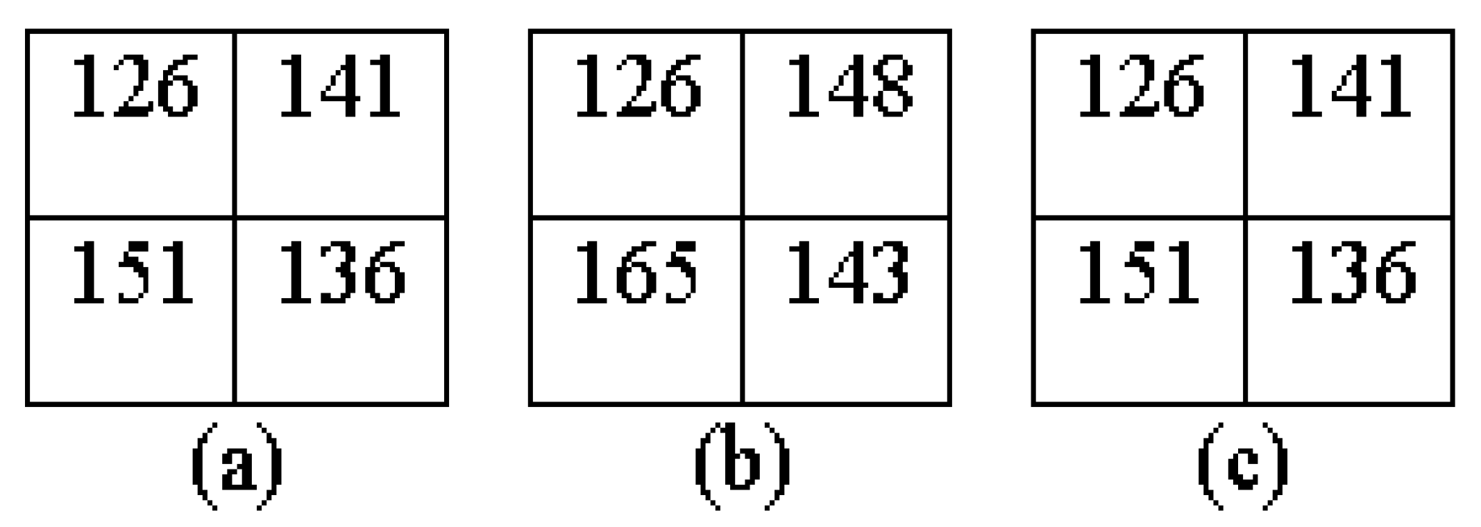
Assume that the quad block of the grayscale image
I is shown in
Figure 3a. Allow two thresholds, T1 = 2 and T2 = 10; the example of the embedding process is presented as follows:
Step 1. Encode the message: Assume that the binary secret bits, , is embedded. Then, it is encoded into the integer values
Step 2. Transform the block into the vector
Step 3. Sort the vector in an ascending order to obtain vector
Step 4. Compute the difference values
by using Equation (5).
Step 5. The given threshold
, so
. Then, reduce the difference value
by using Equation (6).
Step 6. Embed the data: If
, then
are expanded to embed the secret data by using Equation (8).
Step 7. Update the new vector
using Equation (9)
Step 8. Reverse the convert vector
into the correct corresponding positions of the stego-block as shown in
Figure 3b.
3.3.2. An Example of the Extraction Process
Step 1. First, the stego-block is transformed into the vector
. Next, sort the vector
in ascending order to obtain the vector
. Then, calculate the difference values
by using Equation (5).
Step 2. Extract the embedded data
B. The integer values
are extracted in Equation (10).
Convert a sequence of the integer values into the original secret bits
Step 3. Restore the difference values
by using Equation (11)
Step 4. Calculate the original difference values
by using Equation (12).
Step 5. Restore the original vector
using Equation (13).
Finally, convert the vector
into correctly corresponding positions of the original block as shown in
Figure 3c.
4. Experimental Results
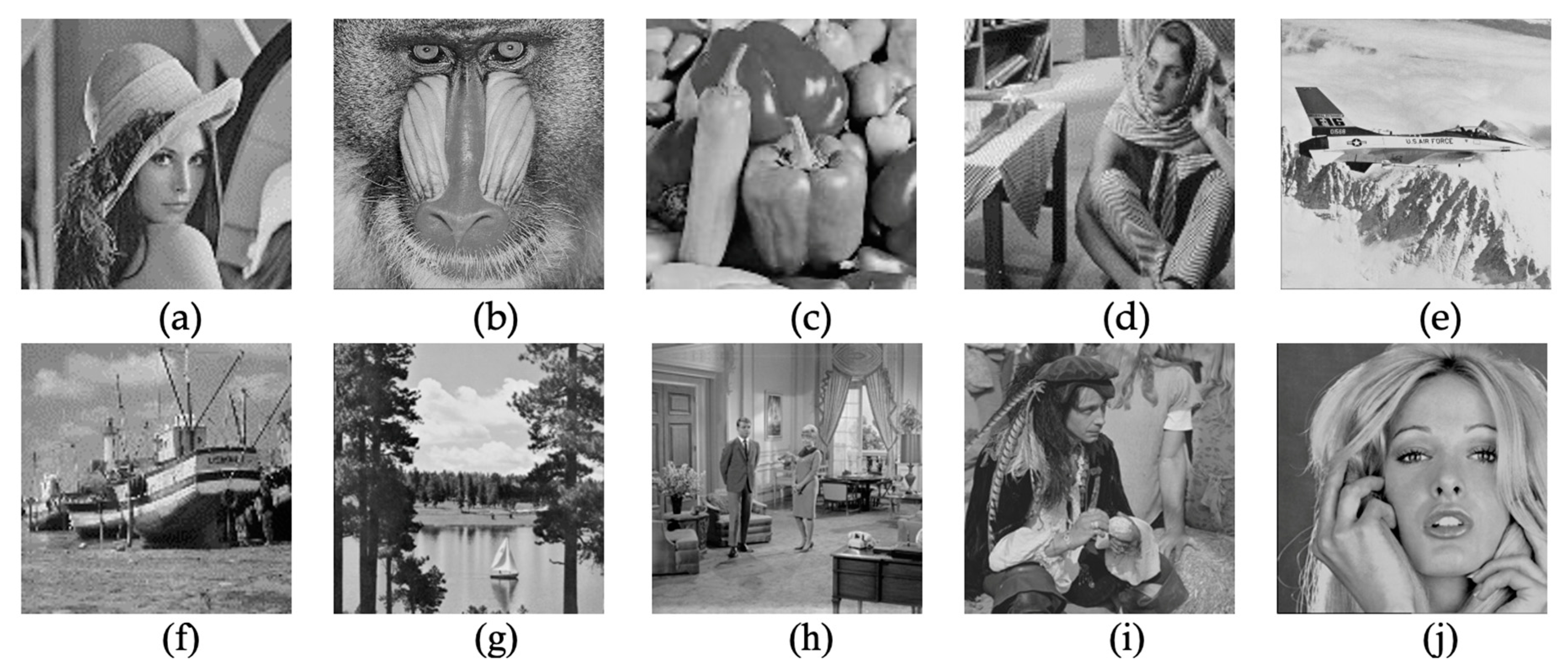
In this section, we present the experimental results of the proposed scheme. These results are experimented on ten common grayscale images. All the images are 512 × 512 with different complexity including Lena, Baboon, Peppers, Barbara, Airplane, Boat, Lake, Livingroom, Pirate and Woman, as shown in
Figure 4. The experimental environment is MATLAB R2014a running on Microsoft Windows 10 Professional 64-bits, and the processor platform is an Intel(R) Core (TM) i7-8700U CPU (12MB Cache, 3.20 GHz), 8 GB of RAM DDR4 memory.
The proposed scheme achieves high performance in terms of the embedding capacity and the visual quality. In this scheme, the message in binary form is first converted into decimal form, then one decimal is embedded into each difference value. Due to one decimal value being equal to two bits, the bit rate of the proposed scheme would certainly improve twice compared to previous schemes. This is becauese only one secret bit is embedded into the pixel pair in previous schemes. In their scheme, the expansion of difference values for embedding decimal values may lead to a negative impact on the image quality and there will also be overflow/underflow problems. To solve this problem, we proposed a new algorithm to reduce the original difference value using an improved ERDE technique. In the proposed ERDE technique, the difference value is minimum modified to embed the secret decimal value. It means the large amounts of secret bits can be embedded while maintaining good imperceptibility and avoiding the overflow/underflow problems.
To compare the image quality, the peak signal-to-noise ratio (PSNR) is used to calculate the visual similarity between a cover image and a stego-image. The PSNR is calculated as Equation (14).
where MSE is the mean squared error representing the difference between the cover image and stego-image and is calculated as Equation (15).
with
and
as the height and width of the image, respectively, and
and
refer to the pixels coordinate at the
ith row and
jth column of the cover image and stego-image, respectively.
Beside the PSNR, the embedding capacity (EC) and bit per pixel (bpp) are also common factors to evaluate the performance of the RDH schemes. The EC is the number of bits which are embedded inside the cover image. The bpp is determined based on the rate of bits which is embedded into one pixel.
To improve the PSNR value, we applied the proposed ERDE algorithm with an optimal reduced threshold
. In our experiment, with
equal to 2, the ERDE scheme achieves the best performance. In the proposed scheme, the difference values are first reduced by ERDE technique, and then two bits are encoded into decimal and embedded into one reduced value. This leads to the proposed scheme to improve the embedding capacity while maintaining a good visual image. Additionally, to prevent the overflow/underflow problems, the embedding threshold
is used to decide whether a block is embeddable or non-embeddable. The block is embeddable if the difference value of this block is smaller than or equal to
; otherwise, this block is ignored. Depending on the length of the secret data, the value of T2 is selected accordingly. A large value of
means more data to be embedded and more distortion in the cover image. Moreover, if T2 is too large, overflow/underflow problems may occur. In the experiment, we try to test several
with values of 2, 4, 6, 8, 10.
Table 1 shows overflow/underflow blocks of common images with T2 = 10 and T2 = 12.
To evaluate how the threshold
impacts on PSNR and EC, the
Figure 5 shows the embedding capacity and the image quality of the Lena image with different values of T2. We see that when T2 is increased, the number of embedded bits significantly increases. However, the quality of the stego-image Lena decreases.
To evaluate the performance of the proposed scheme, the comparison of the embedding capacity and image quality between the proposed scheme and previous schemes, including Arham et al.’s scheme [
22], Ntahobari & Ahamd’s scheme [
23] and Maniriho et al.’s scheme [
28], are shown in
Table 2. It can be seen in
Table 2, with T2 = 12, that the proposed scheme achieves higher embedding capacity than T2 = 10. However, the overflow/underflow problems will occur in some images with T2 = 12. In the proposed scheme, the best result of EC and PSNR is obtained when the value of T2 is in the range of [2, 10].
In the proposed scheme, each difference value can embed two bits after applying the ERDE technique. As a result, our average embedding capacity of all test images is up to 311,966 bits, whereas the EC of Arham et al. [
22], Ntahobari & Ahamd scheme [
23], and Maniriho et al.’s scheme [
28] is 177,924 bits, 185,284 bits and 242,146 bits, respectively. Although the EC increased by 68%, the proposed scheme also achieves a better visual image than that of Ntahobari & Ahamd’s scheme, which reached 33.43 dB and 31.95 dB, respectively. From
Table 2, the PSNR value of the proposed scheme slightly decreased compared to Arham et al.’s scheme with maximum data embedding. However, when two schemes are embedded the same embedding capacity, the PSNR value of the proposed scheme is always better than that of Arham et al.’s scheme.
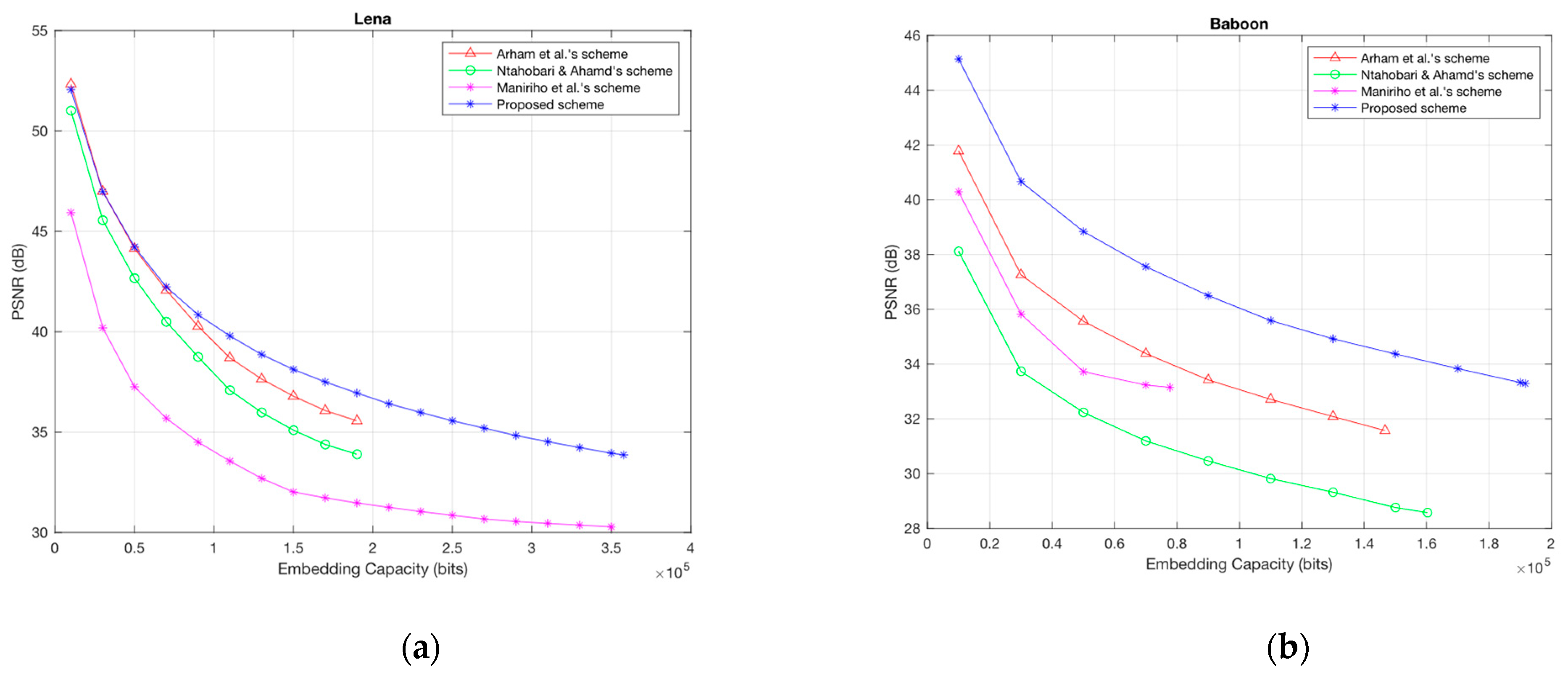
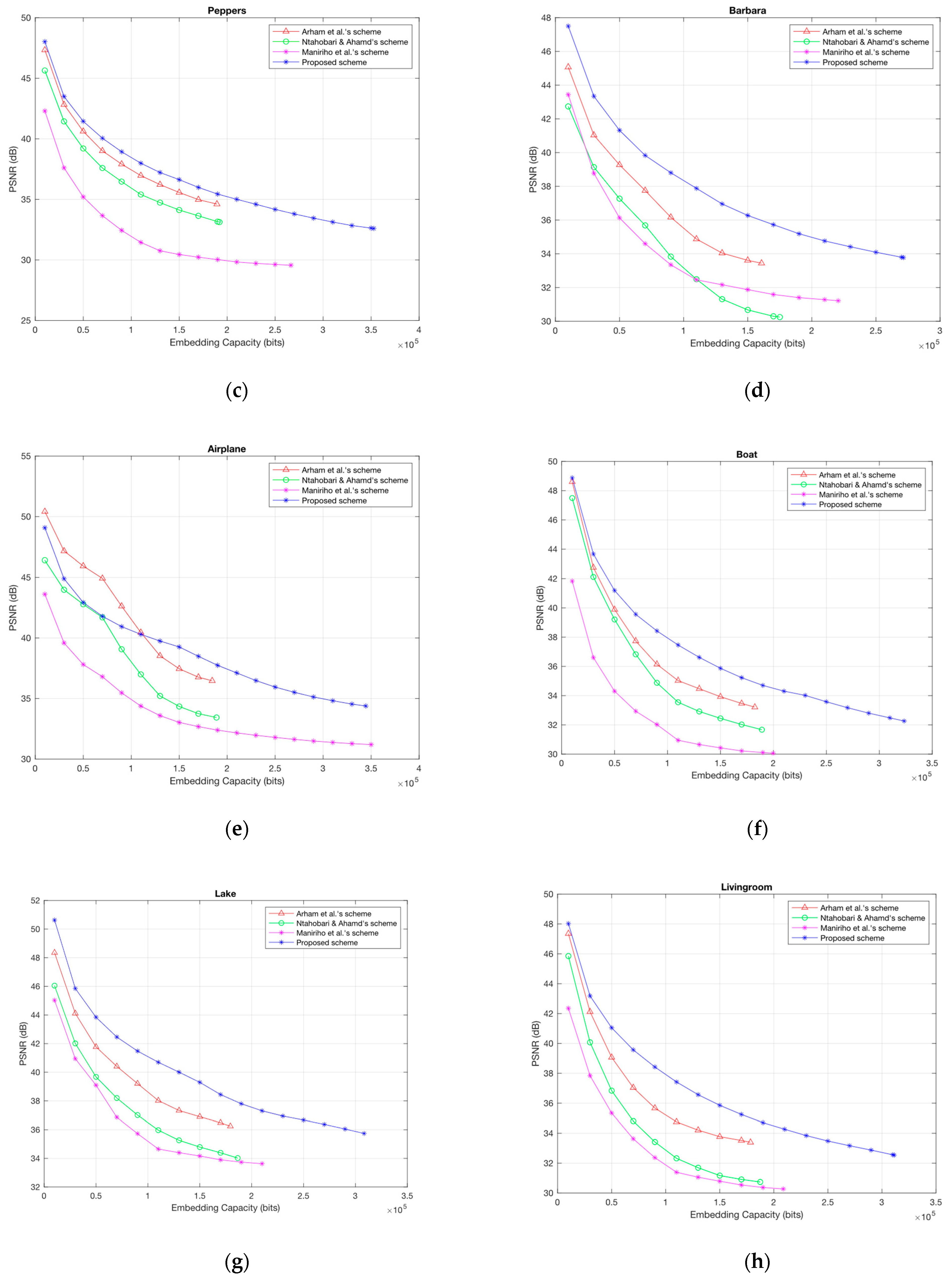
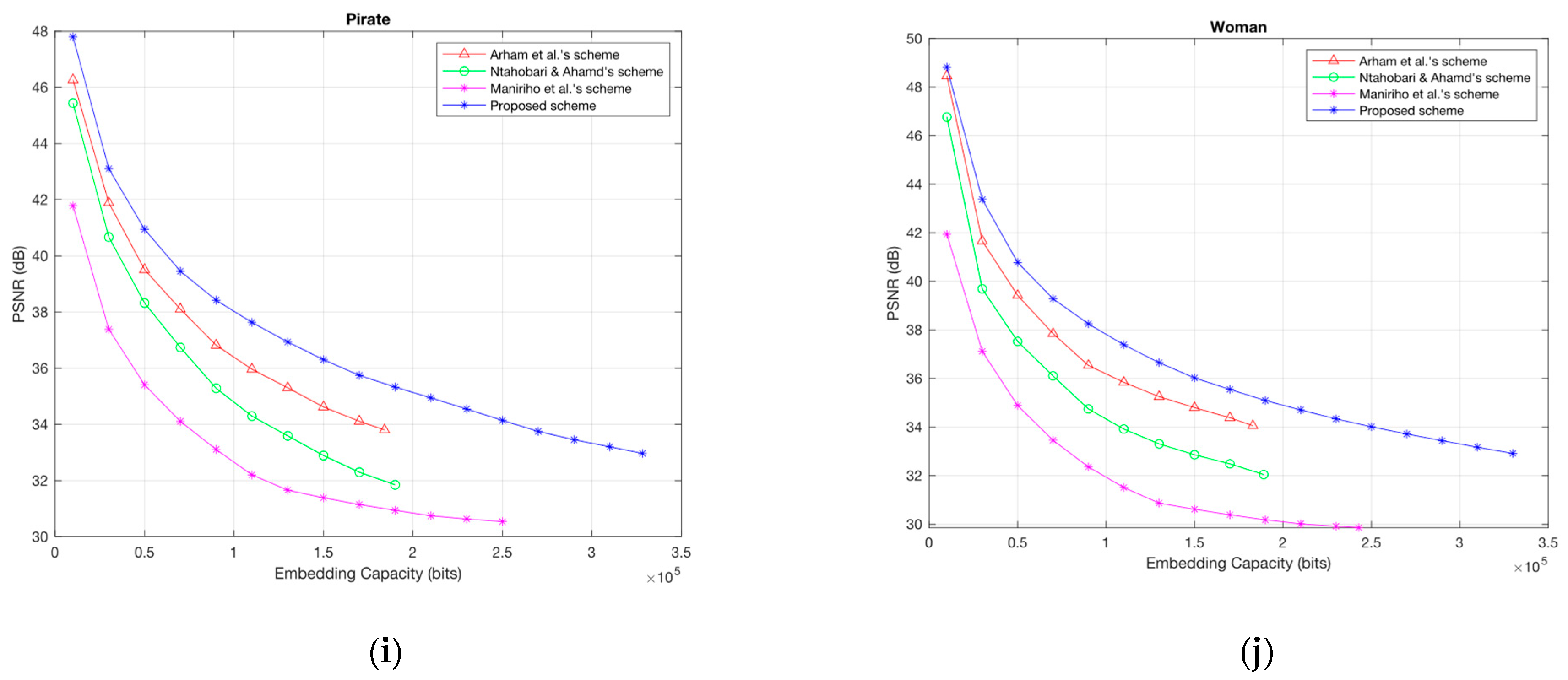
To demonstrate the outstanding effectiveness of the proposed scheme, the PSNR comparison in dB between the proposed scheme and previous schemes is shown in
Figure 6a–j. From the graph, we can see that in most cases, the proposed scheme is better than the other schemes with the same embedding capacity rate. Moreover, the proposed scheme can obtain a much higher maximum EC than previous schemes. For example, the EC of the proposed scheme for the Lena image is greater than 350,000 bits. However, for Arham et al.’s scheme [
22] and Ntahobari & Ahamd’s scheme [
23], the EC is only around 190,000 bits and 194,000 bits, respectively.


