
Comparative Study on the Influence of Different Forms of New Tubular Roof Method Construction on Railway Tracks


Abstract
:1. Introduction
2. Research Background
2.1. Characteristic of the New Tubular Roof Method
- The NTRM generally uses large-diameter steel tubes (about 2 m in diameter), while the tube diameter of the traditional tube roof method is generally less than 1 m, mostly 600~900 mm;
- The NTRM generally adopts a pre-built integrated structure. The tube roof directly forms a permanent structure with concrete filled in, and no extra lining is applied. The traditional tube roof method generally adopts a composite lining design, and the tube roof is only used for advanced support and initial support;
- The NTRM usually adopts cutting-welding and inter-tube grouting to realize the connection between the tubes, while the traditional tube roof method usually adopts the tenon connection.
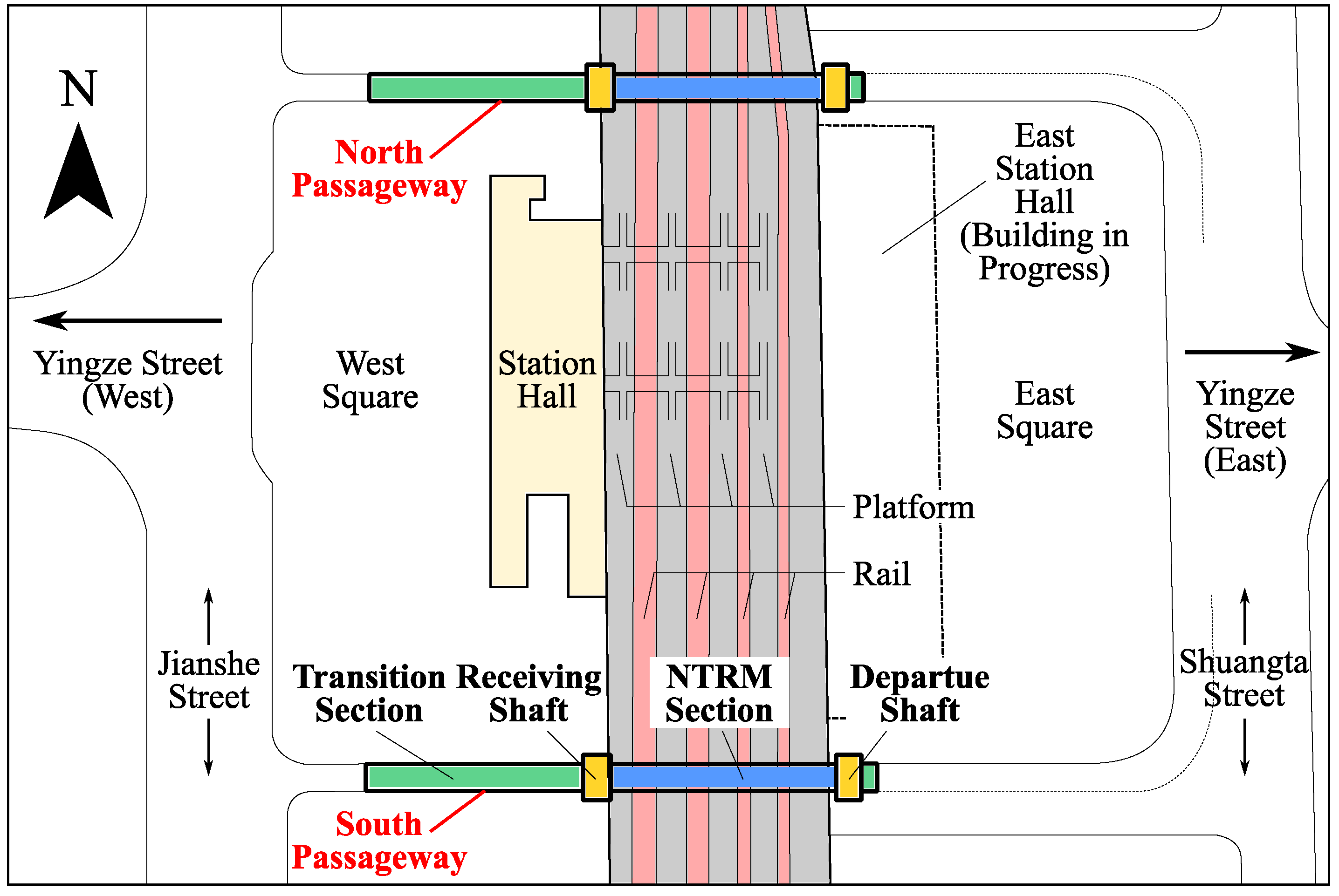
2.2. Project Overview of TYSU Project
2.2.1. General Situation of Project
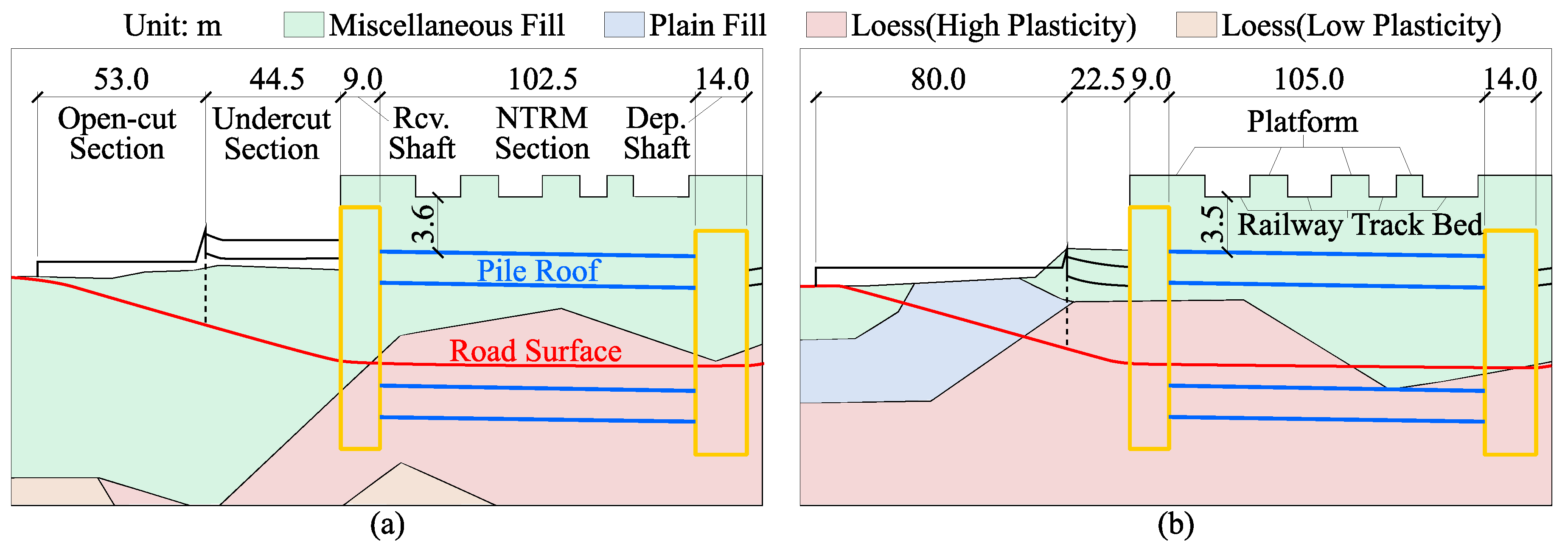
2.2.2. Strata Condition
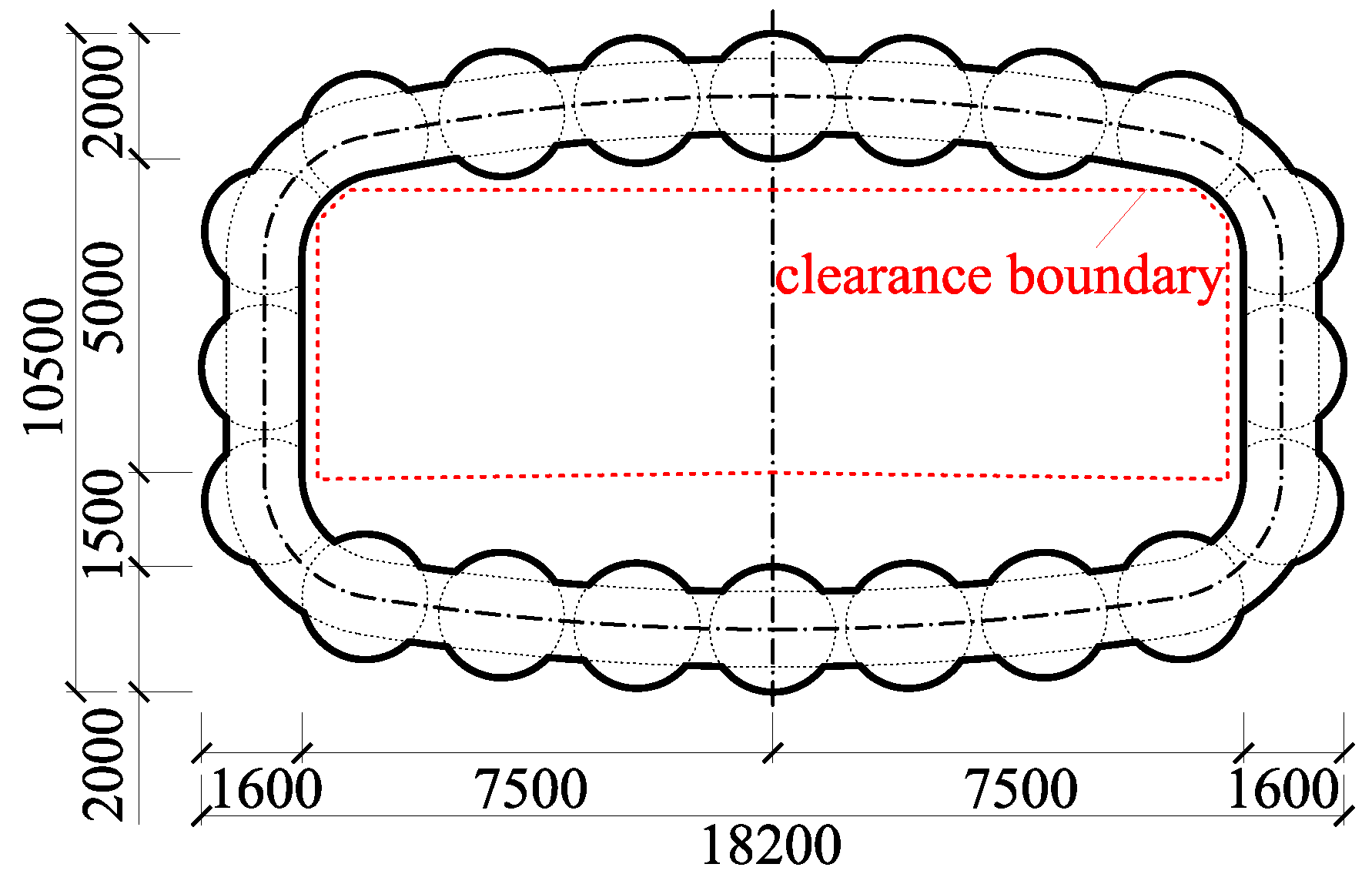
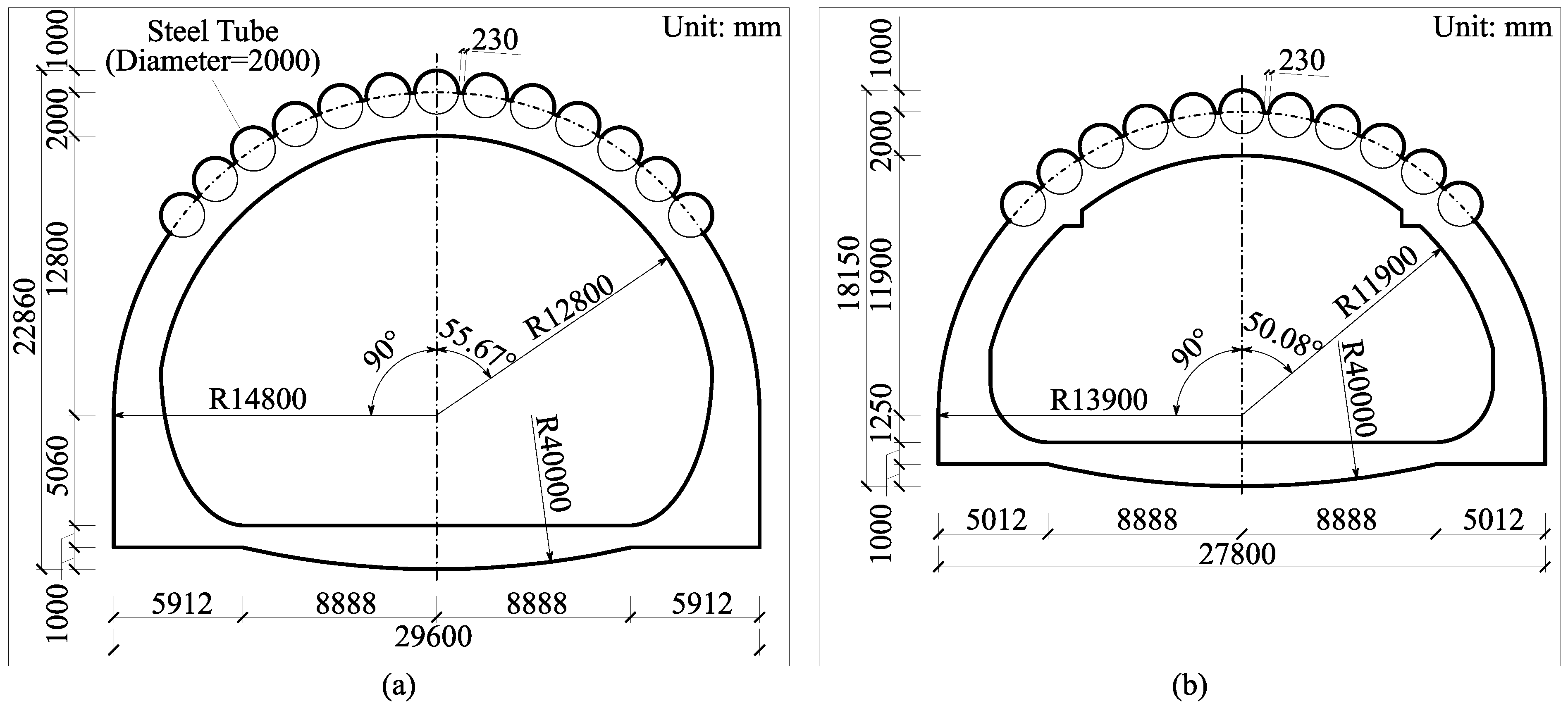
2.2.3. Cross Section and Structural Form of Passageway of TYSU Project
2.2.4. Construction Process
- Construction of working shafts:
- 2.
- Pre-supporting by the pipe shed:
- 3.
- Tube jacking:
- No. 1 jacking machine: A14, A16, A15, A18, A17, A20, A19, A2, A1, A3.
- No. 2 jacking machine: A12, A13, A10, A11, A8, A9, A6, A7, A4, A5.
- 4.
- Tube incision, connection and inner support:
- 5.
- In-tube rebar binding and concrete pouring:
- 6.
- Excavation and internal structure construction:
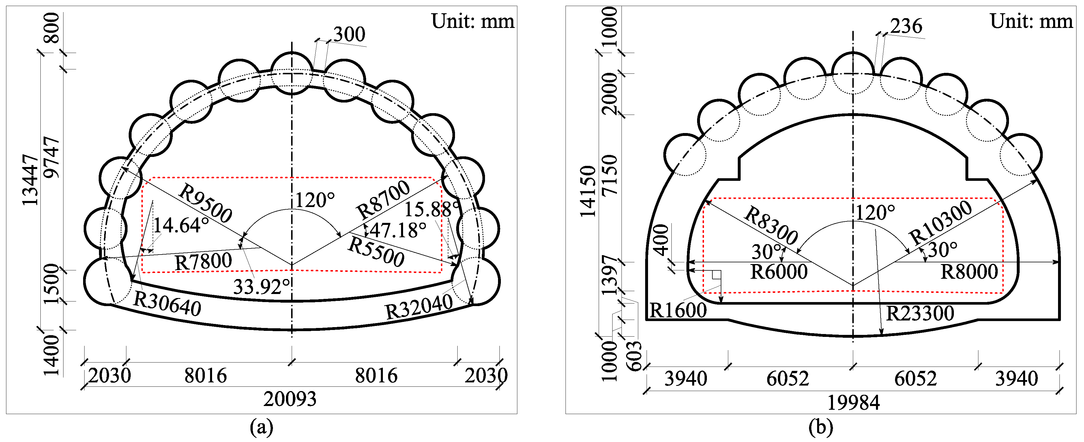
2.3. Overview of the Projects to Be Compared
2.3.1. Xinle Ruins Station of Shenyang Metro Line 2
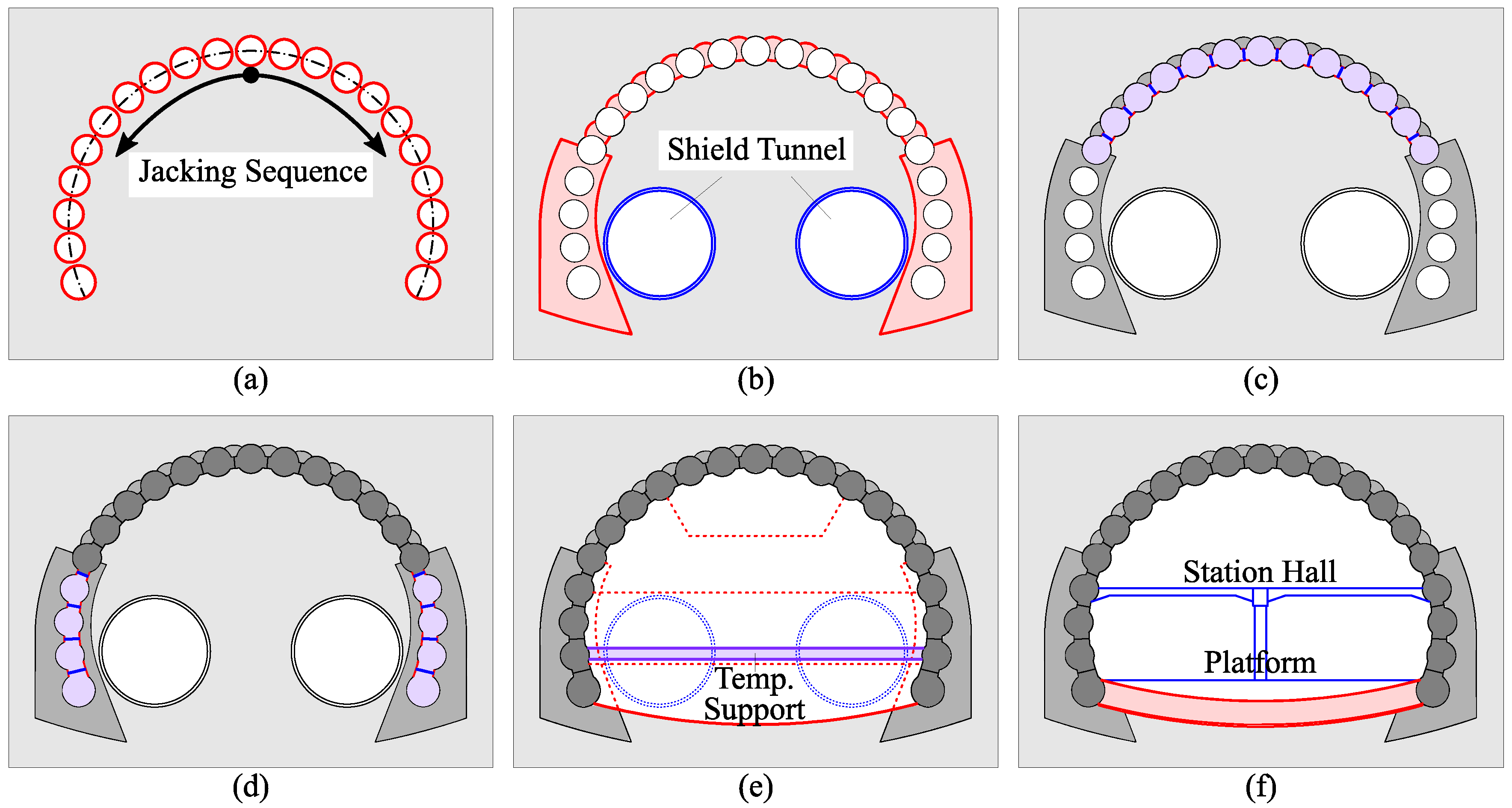
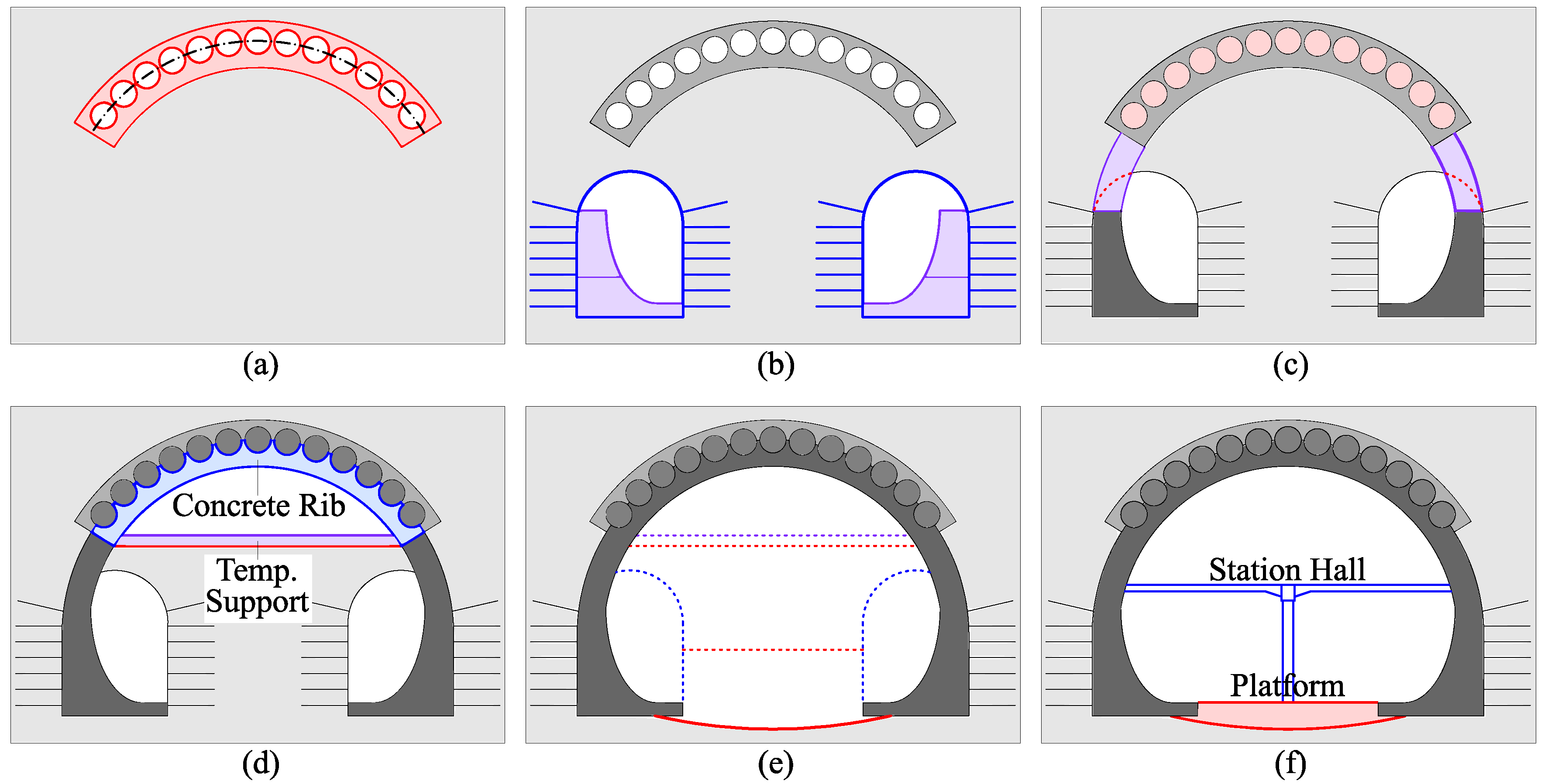
- Build the working shafts and perform tube jacking. The jacking sequence is from the top of the vault to the foot of the side wall, left and right symmetrically (Figure 8a);
- Carry out grouting reinforcement of the soil between the tubes and the arch foot area. During this period, the shield machine responsible for the construction of the section tunnel passed through the station from the platform level (Figure 8b);
- Perform the incision, connection, rebar binding and concrete pouring in the steel tubes on the station hall level (Figure 8c);
- Perform the incision, connection, rebar binding and concrete pouring in the steel tubes on the platform level (Figure 8d);
- After the concrete reaches the expected strength, the internal soil is excavated in layers. During this process, the shield segments are removed, and temporary steel supports are arranged at the lower part of the side wall (Figure 8e);
- Construct the inverted arch, and then complete the internal structure from bottom to top (Figure 8f).
2.3.2. Lot 923 Station of Seoul Metro Line 9
- Since the site does not have the conditions for building a working shaft, several long steel tubes with a diameter of 2.5 m and short steel tubes with a diameter of 1.5 m are used to build a rectangular tunnel for the tube jacking. Then, the steel tubes of the station mainframe are jacked in. The stratum near the tubes is grouted for reinforcement (Figure 10a);
- Excavate two pilot tunnels on the left and right sides under the tube roof, then construct the side walls of the station inside the pilot tunnel (Figure 10b);
- The side walls are extended upwards and connected to the tube roof, and concrete is poured in the tube (Figure 10c);
- The soil above the arch line of the tube roof is excavated. Then, the transverse ribs and temporary supports are applied (Figure 10d);
- The remaining soil is excavated downward in layers to the bottom of the structure. During this, the support of the pilot tunnel is removed, and the inverted arch is poured. Finally, the internal structure of the station is completed.
2.4. Research Plan
- Case 1: Closed-type, inner-connecting, near-rectangular tubular roof structure, completely supported first and then excavated. Case 1 is called “Taiyuan method”, taking the TYSU Project as the prototype;
- Case 2: Open-type, inner-connecting, arch-shaped tubular roof structure. Excavation takes place after the tube roof is formed. The inverted arch is applied lastly to form a complete structure. Case 2 is called “Shenyang method”, taking Xinle Ruins Station as the prototype;
- Case 3: Open-type, external-connecting, half-arch-shaped tubular roof structure. The lower section of the structure is constructed through the pilot tunnel, and the inverted arch is constructed with the excavation. Case 3 is called “Seoul method”, taking Lot 923 Station as the prototype.
3. Numerical Model
3.1. Basic Assumptions
- The strata are assumed as continuous homogeneous isotropic medium, distributed in horizontal layers, no relative displacement between layers;
- Steel tubes, concrete and structures such as pipe sheds, bolts, and inner support of the tube roof are assumed to be working in an elastic state during construction, their materials are assumed to be isotropic linear elastic media;
- Since the longitudinal axes of the three prototype project are all straight lines, the cross-sectional forms are symmetrical, and the construction steps are basically symmetrical, the symmetry problem can be considered;
- Since the natural water level of groundwater in the TYSU Project, which is the benchmark project, is lower than the structural floor, the effect of groundwater is not considered;
- The effect of tunnel underpass construction on each railway track is the same and independent of each other, so only one track is selected for research.
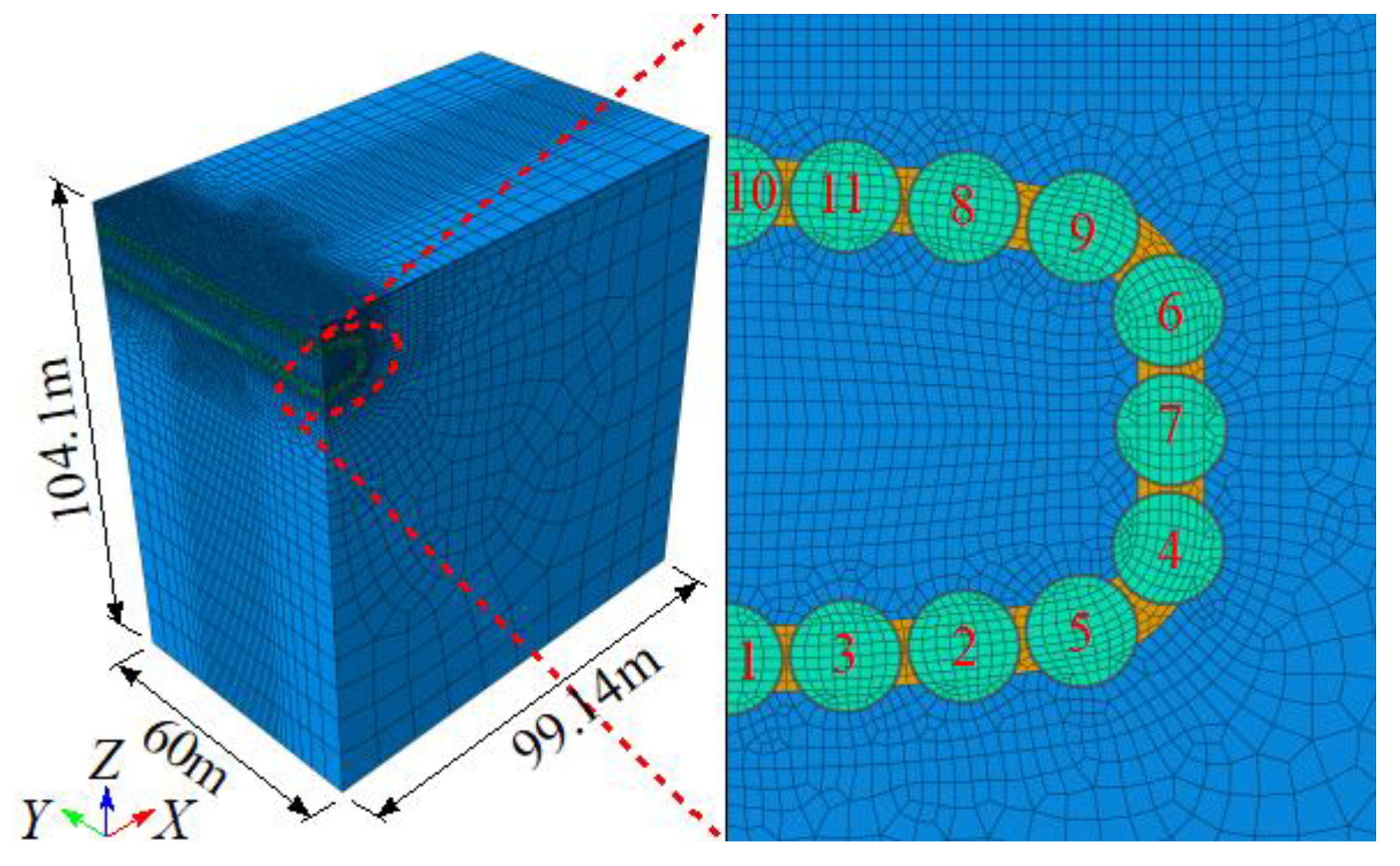
3.2. Model Geometry and Meshing
3.2.1. Model of Case 1
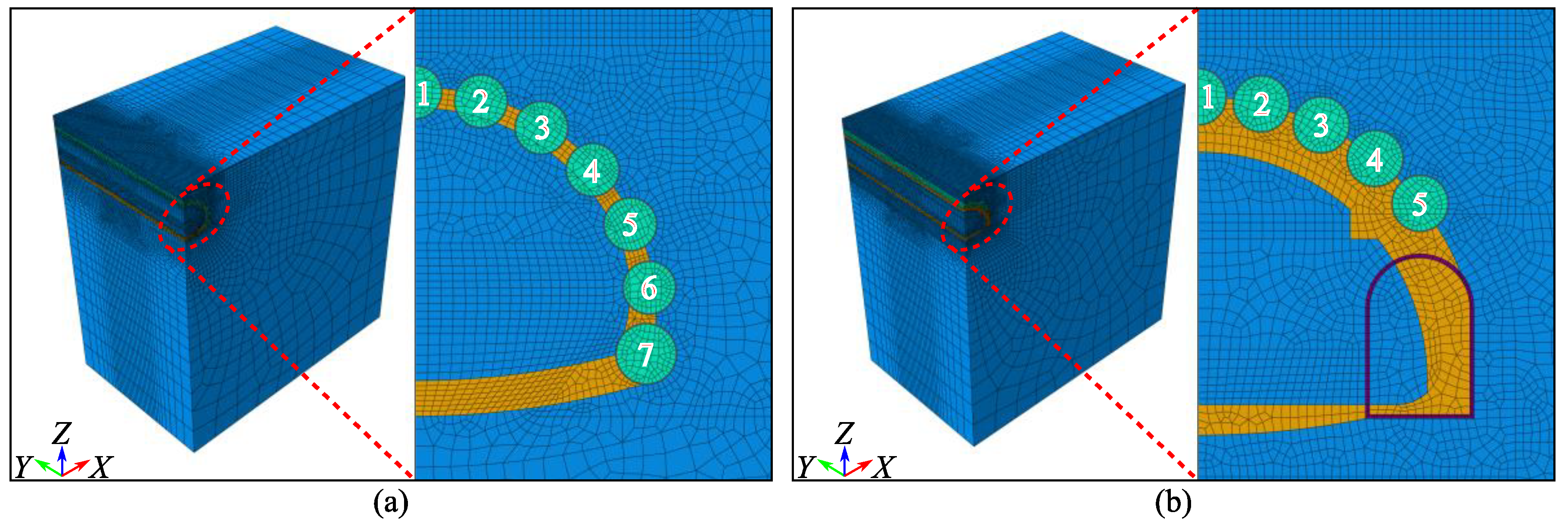
- The cross-sectional plane: 0.2 m;
- The axial direction, middle area of the model: 0.5 m;
- The axial direction, near the model boundary: 1.0 m.
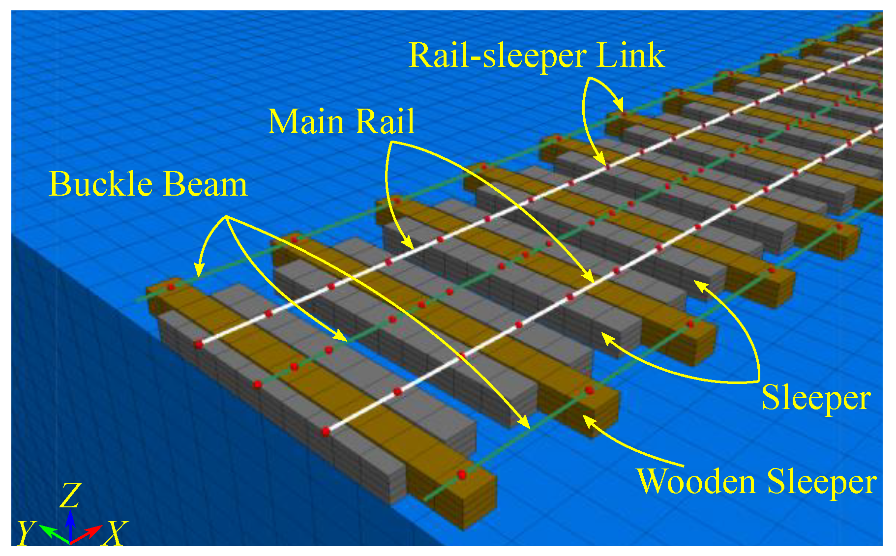
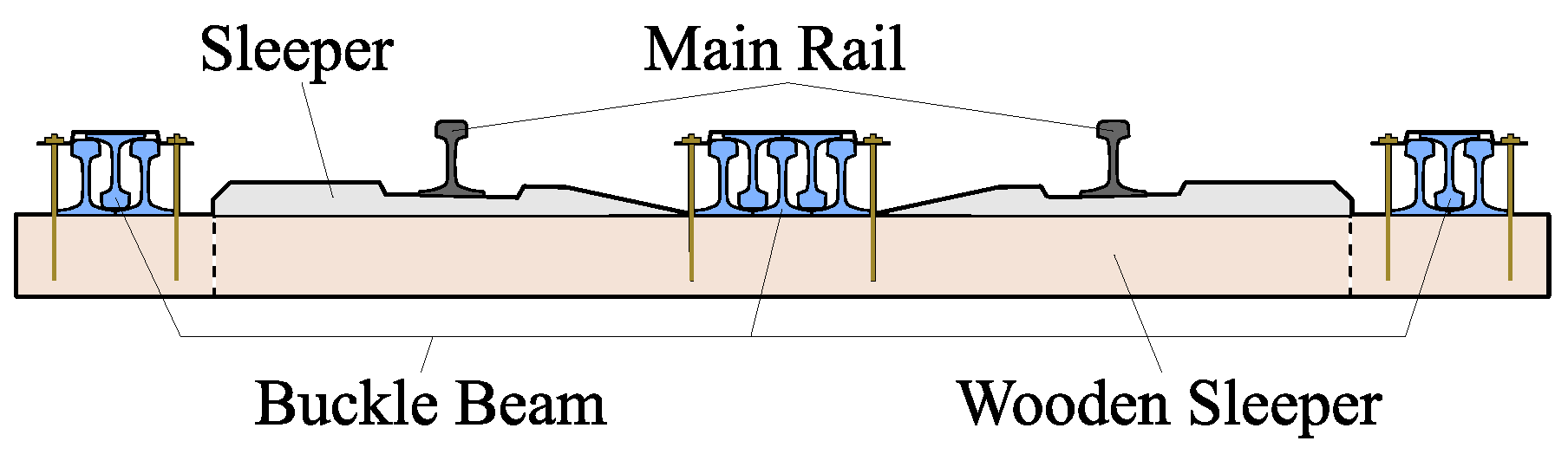
- Every other sleeper, insert a 3.5 m long wooden sleeper as a beam;
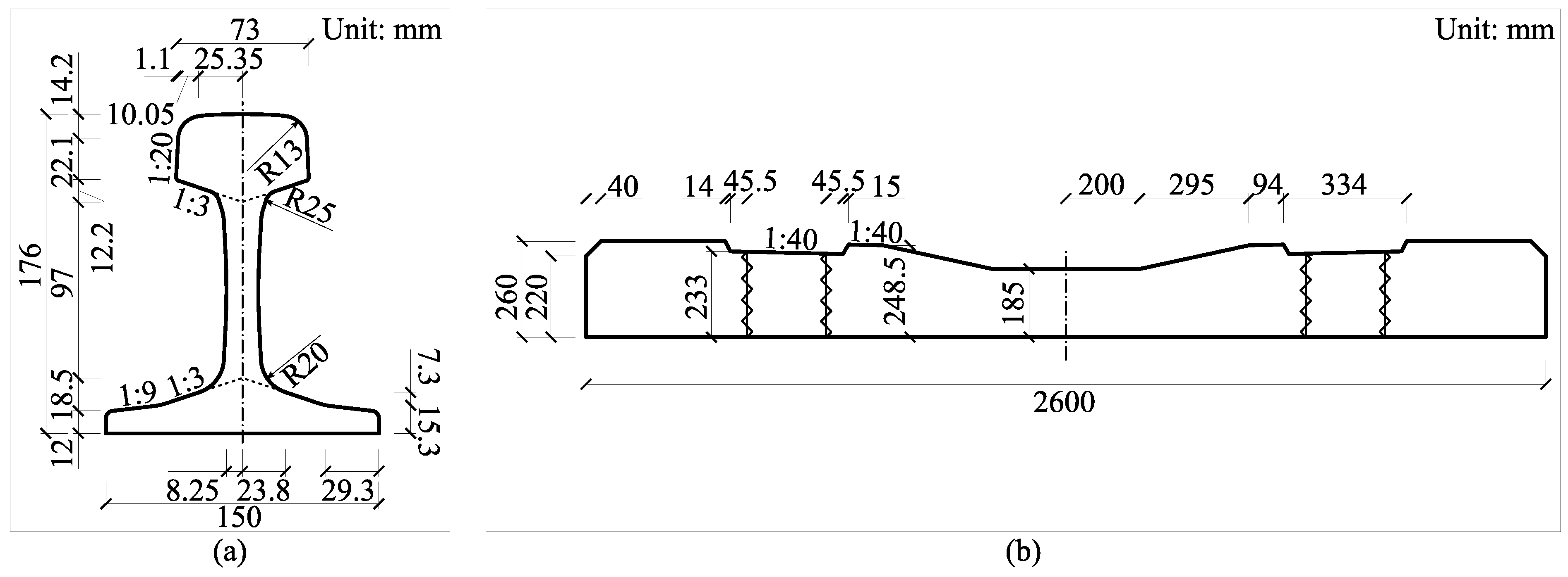
- Several steel rails (the size is slightly smaller than the main line rail) are spliced together to form a buckle beam and placed on the wooden sleeper. There are 3 buckle beams in total. The buckle beams on two sides of the track are assembled with 3 rails, and the buckle beam in the middle of the track is assembled with 5 rails. The cross-sectional diagram is shown in Figure 14;
- After adjusting the position of the buckle beam, use the buckle plate and bolts to connect the buckle beam to the sleeper;
- After the underpass construction is completed, remove the fasteners, buckle beams and wooden sleepers in sequence, then add ballast and tamping, and adjust the shape of the rail.
3.2.2. Model of Case 2 and Case 3
3.3. Constitutive Model and Material Parameters
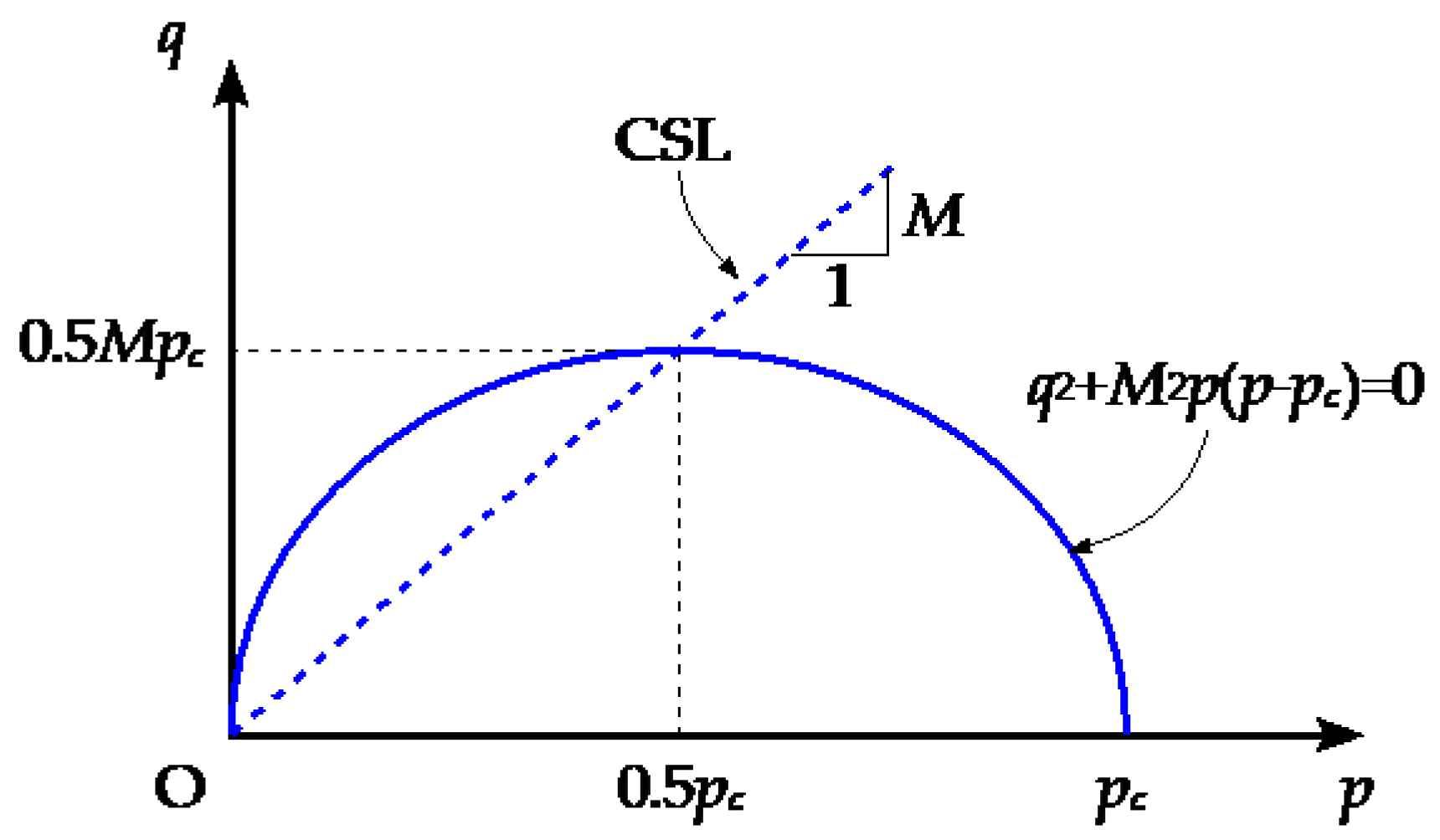
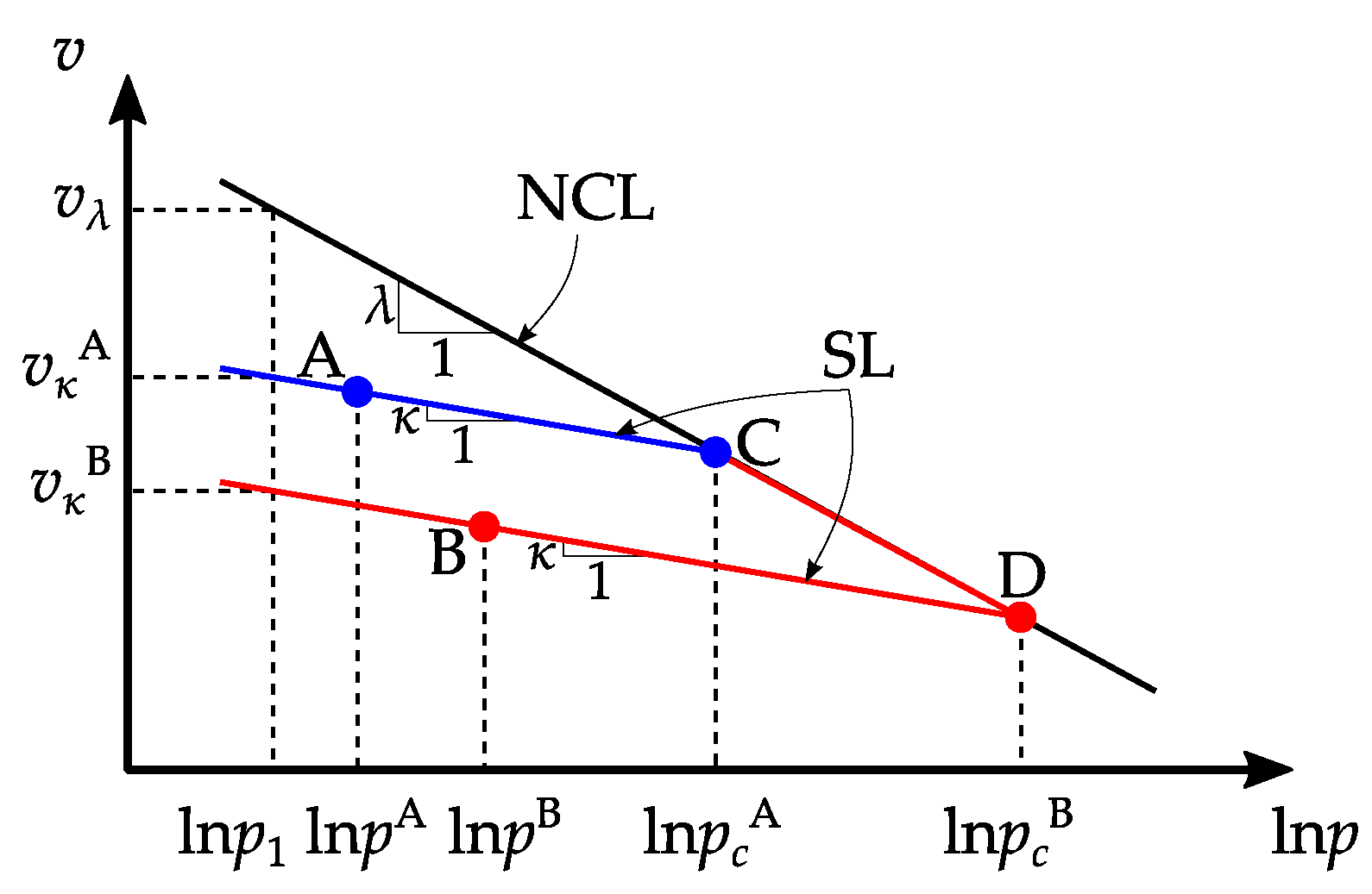
3.3.1. Strata
- The elastic stress–strain relationship of the material obeys Hooke’s law;
- The yielding of the material is only related to the first stress invariant and the second stress invariant, not the third stress invariant;
- Adopts isotropic hardening, and the size of yield envelope is related to the plastic volume compression of the material;
- The associative plastic flow rule is used;
- The plastic work of the material is assumed to be
- Material constants: M, λ, κ.
- Elastic parameters: Poisson’s ratio ν or shear modulus G.
- The coordinates of the reference point on the NCL.
- Initial stress field and normal consolidation pressure field of soil.
3.3.2. Building Materials
3.3.3. Special Element Parameters
3.4. Boundary Conditions
3.5. Initial Conditions and Simulation Flow
- 1.
- Primary geo-stress balance:
- 2.
- Secondary geo-stress balance:
- 3.
- Tube jacking:
- 4.
- Incision, connection, inner supporting and concreting of tube roof:
- 5.
- Soil excavation and permanent structure construction:
- 6.
- Final stress balance:
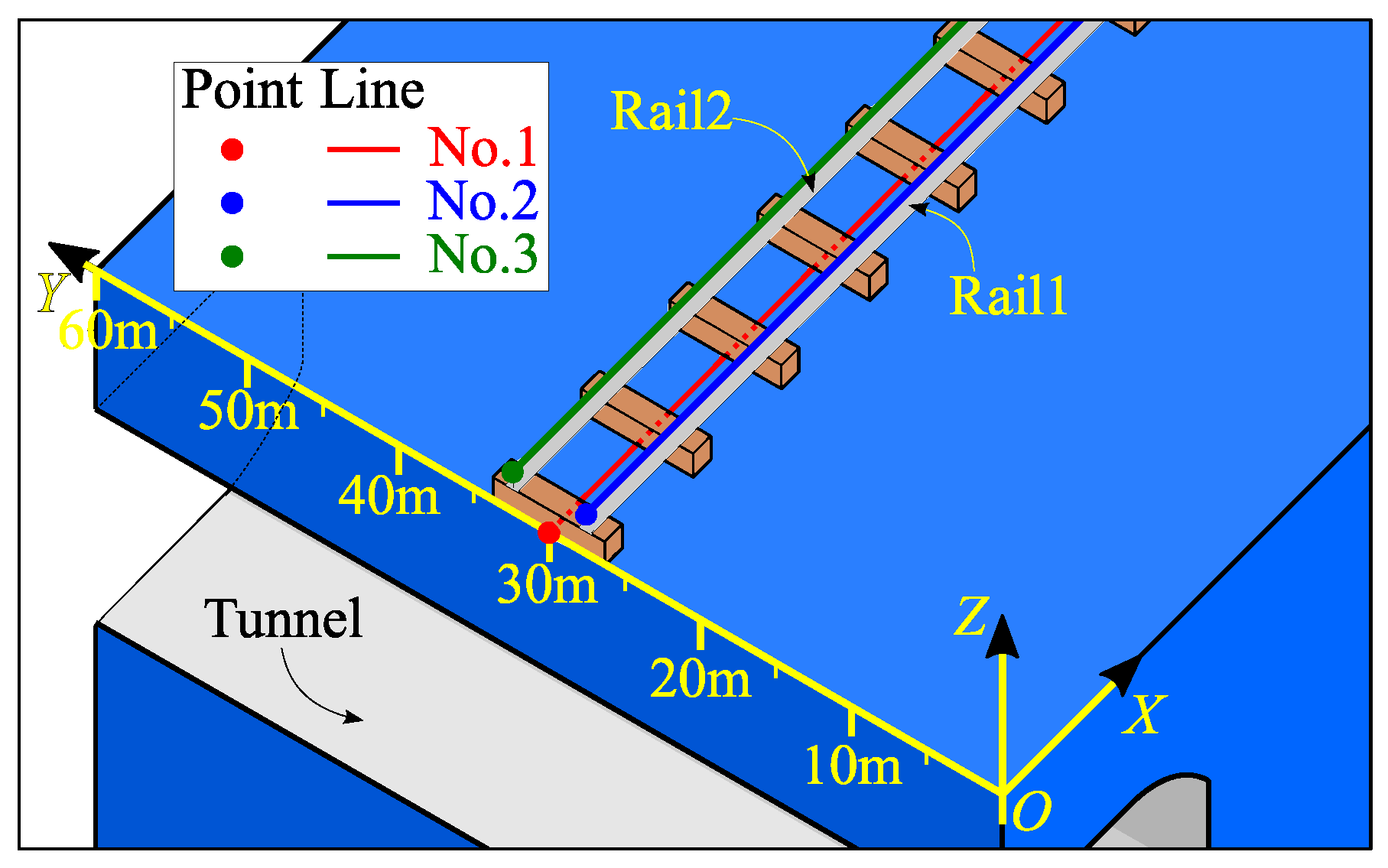
3.6. Measuring Point Layout
4. Calculation Results and Analysis
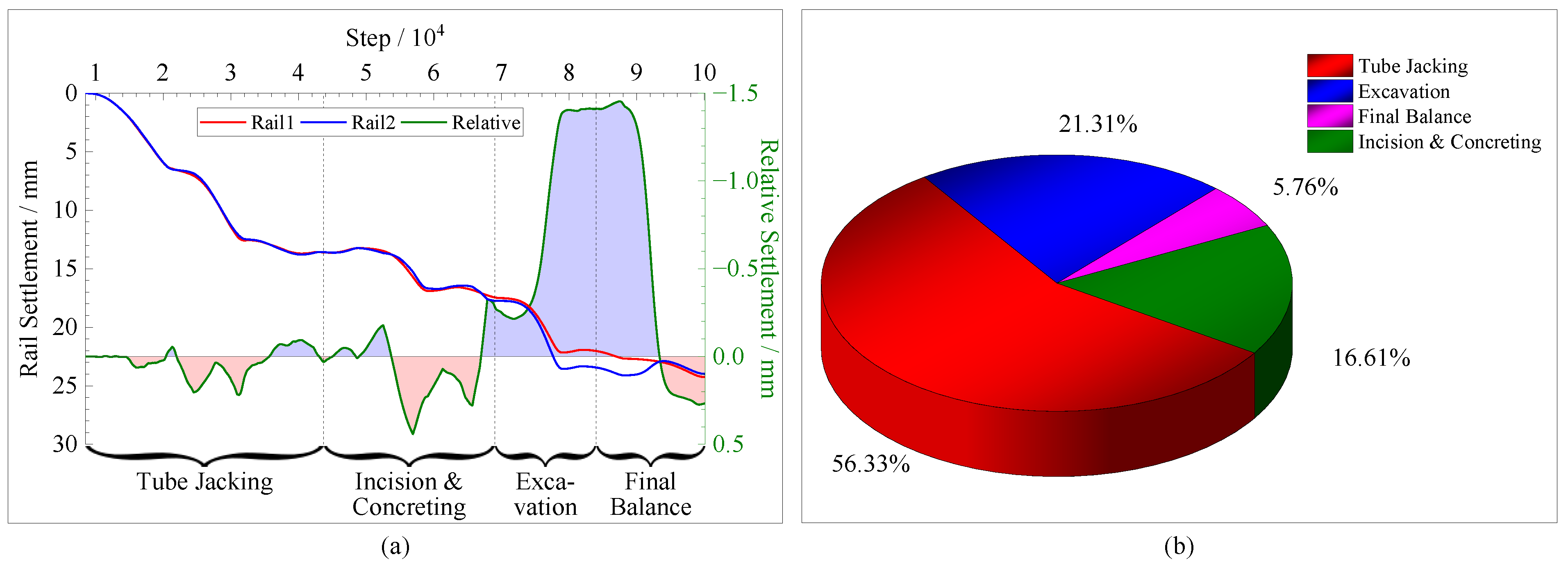
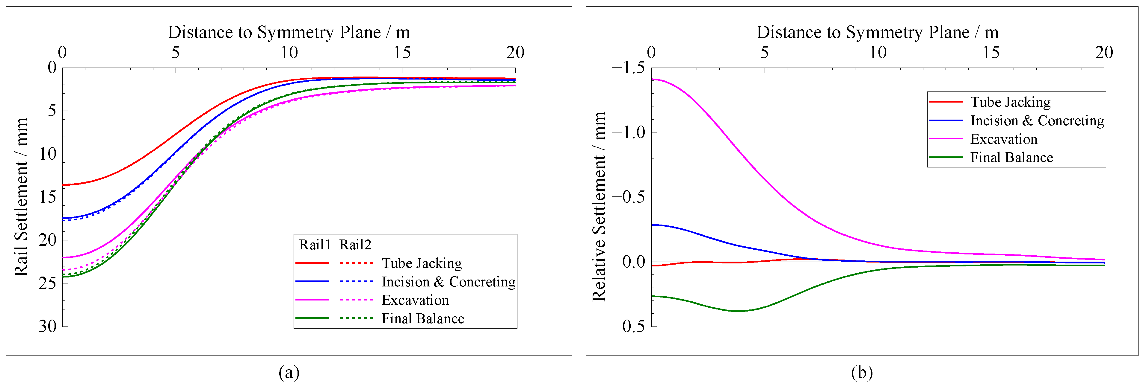
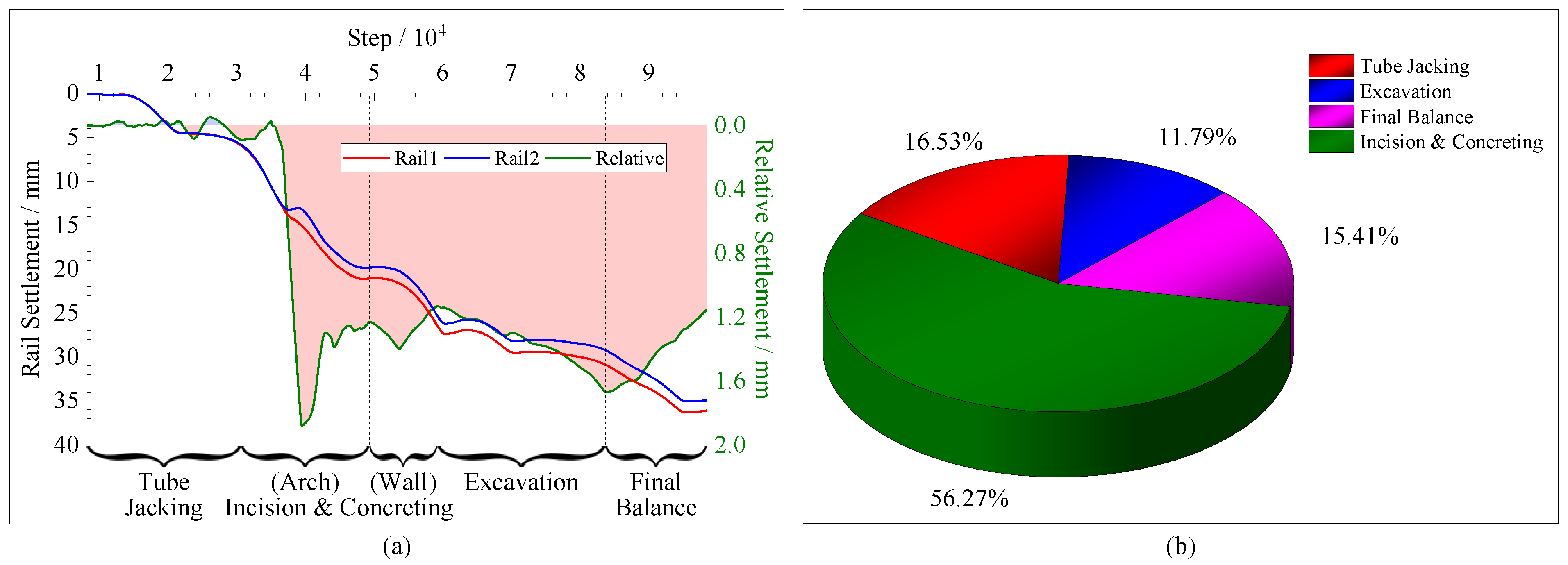
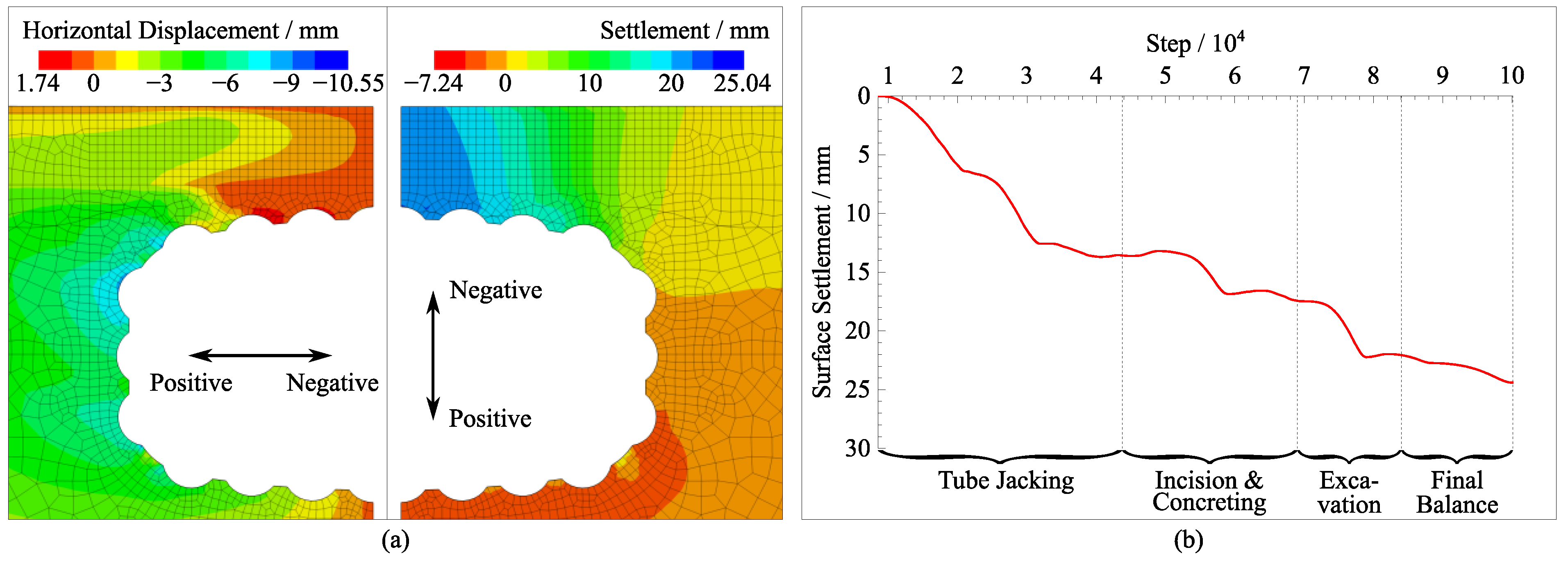
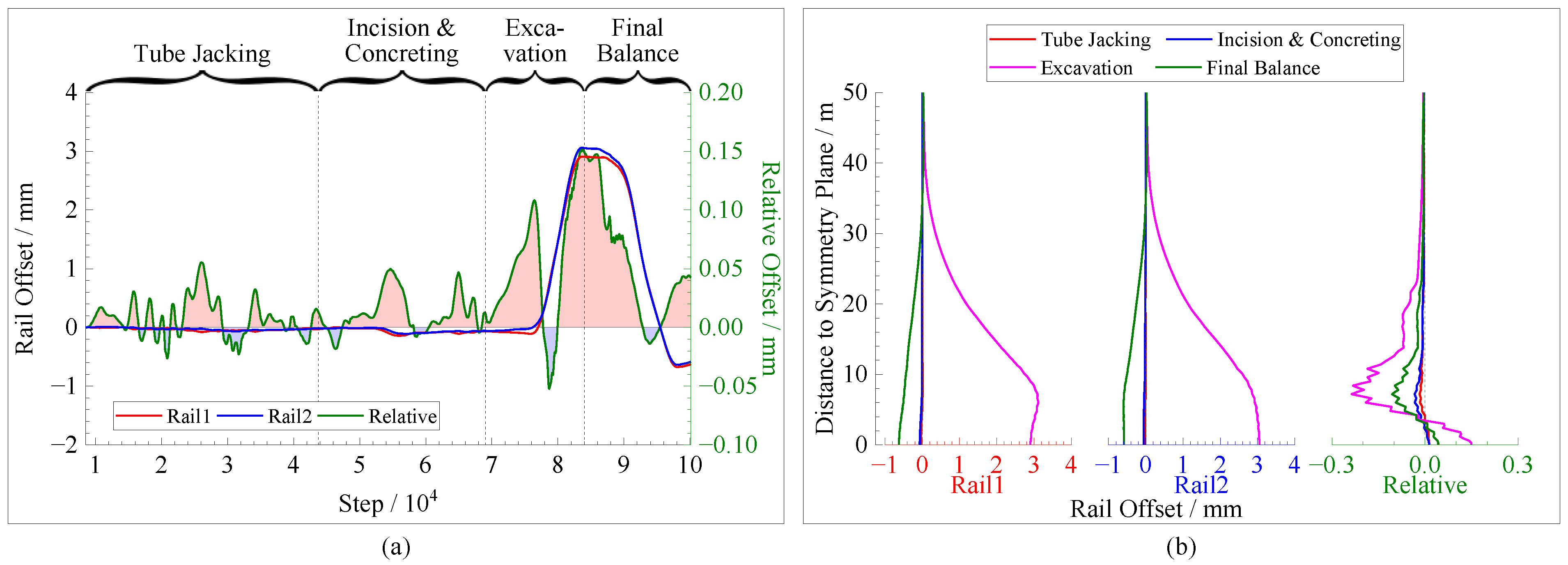
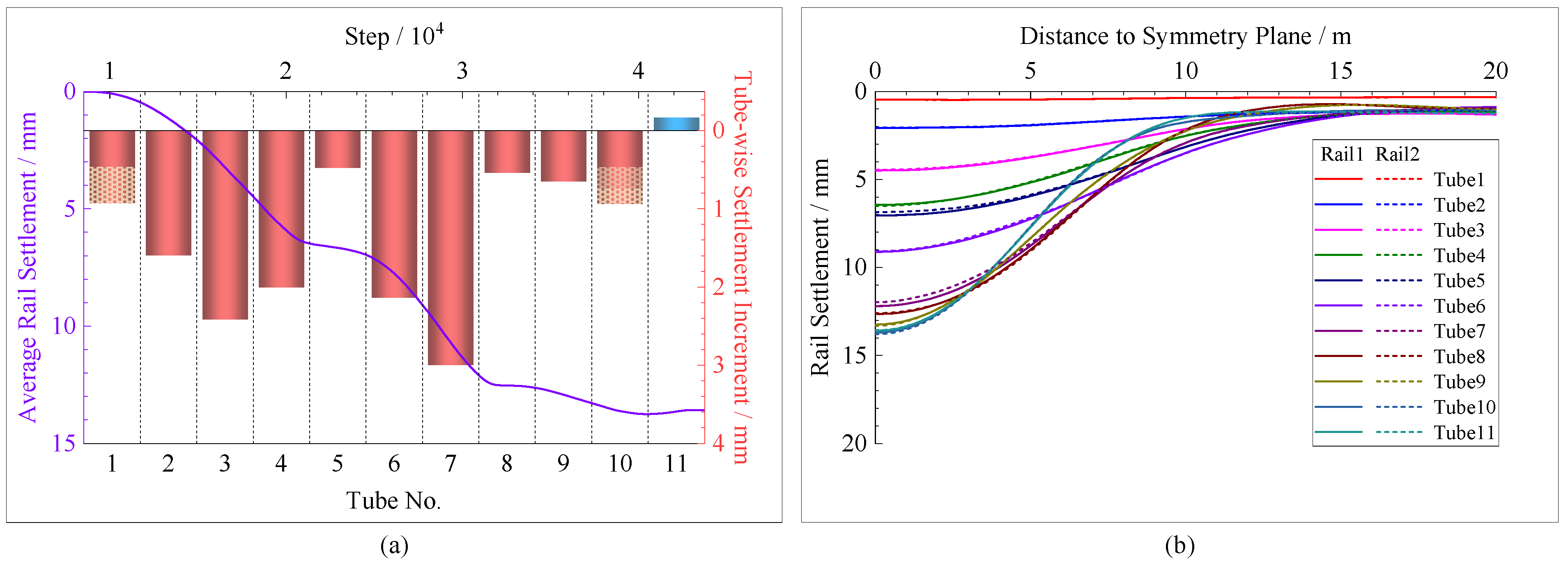
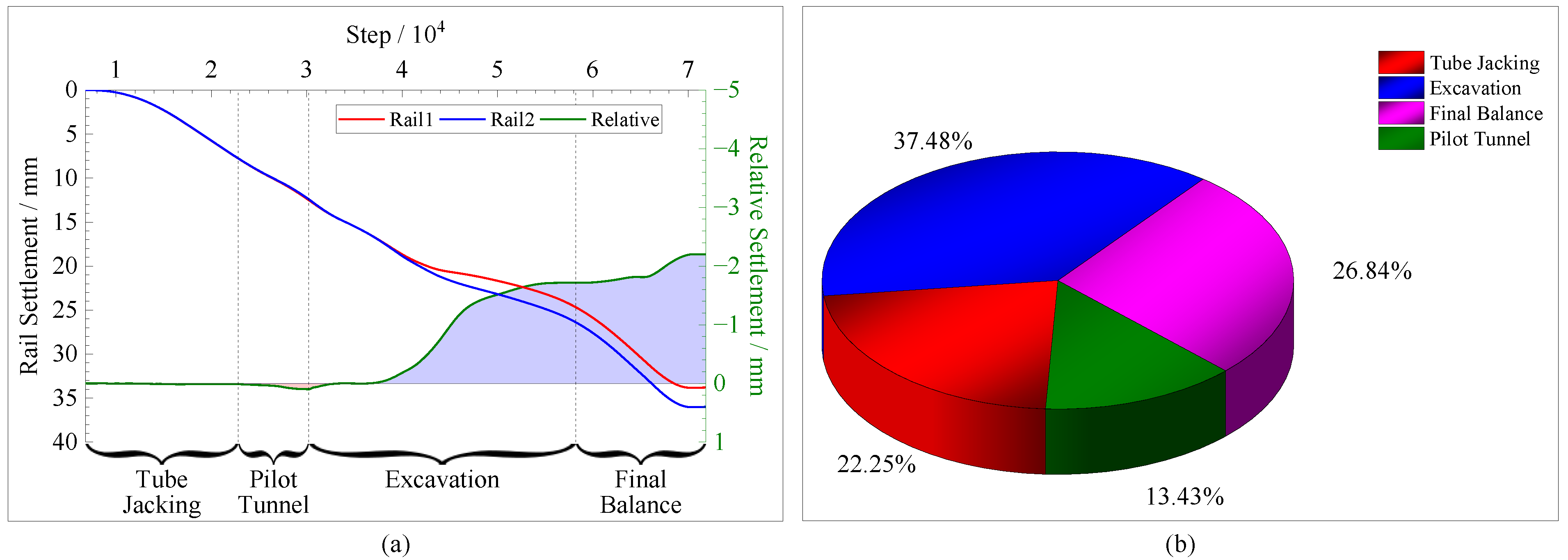
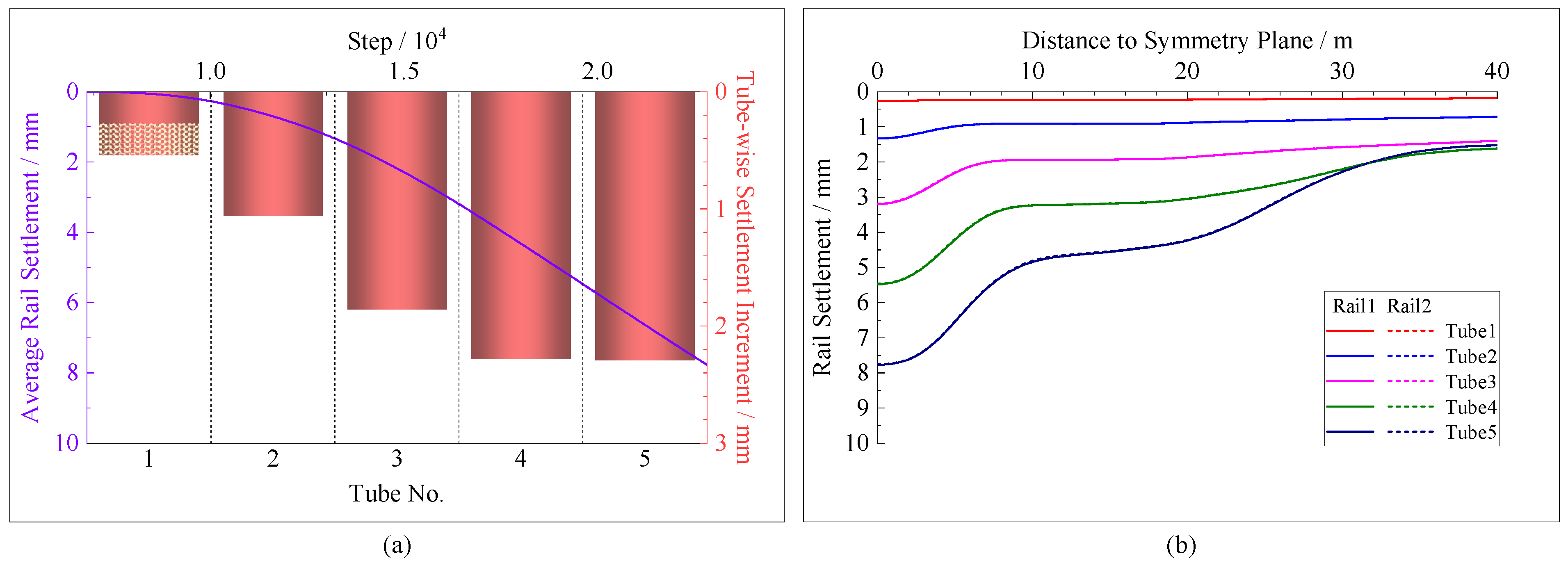
4.1. Case 1
4.2. Case 2
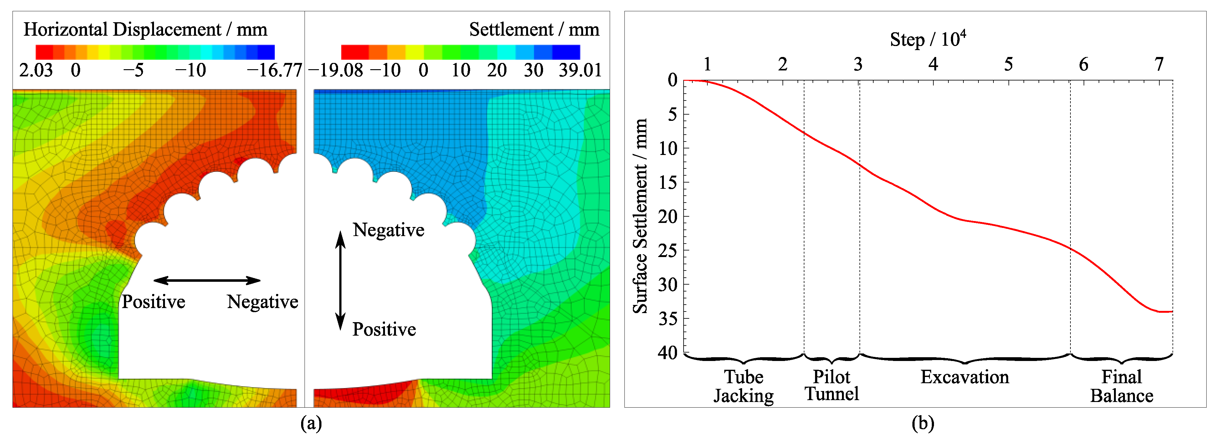
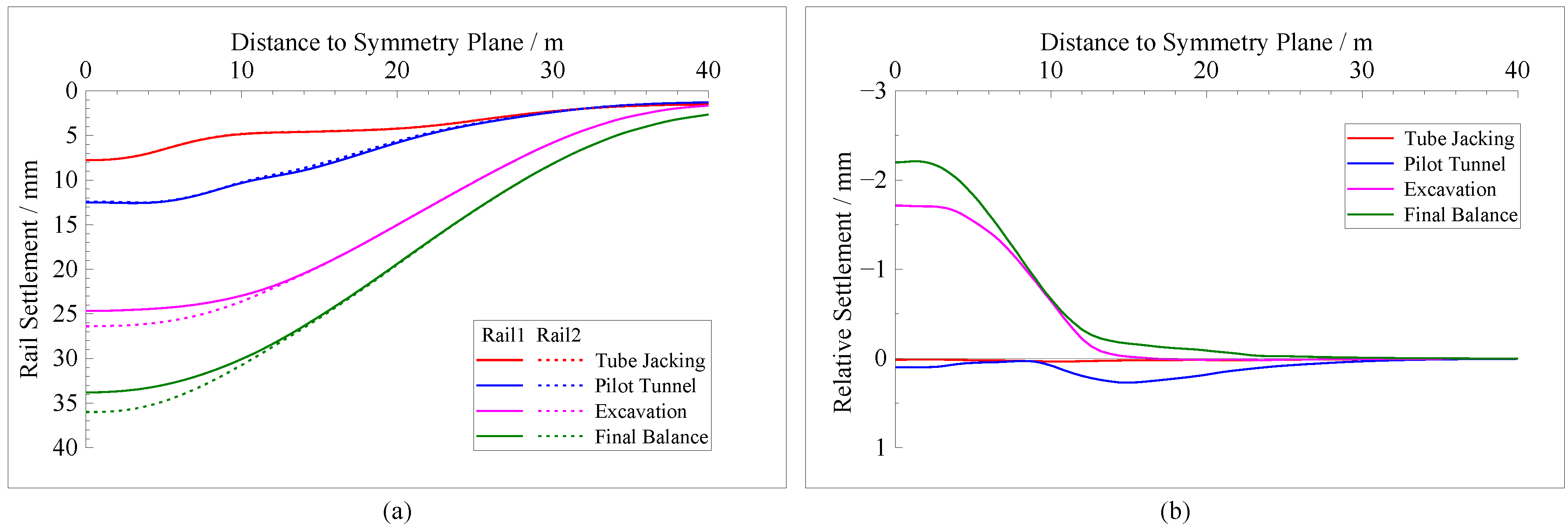
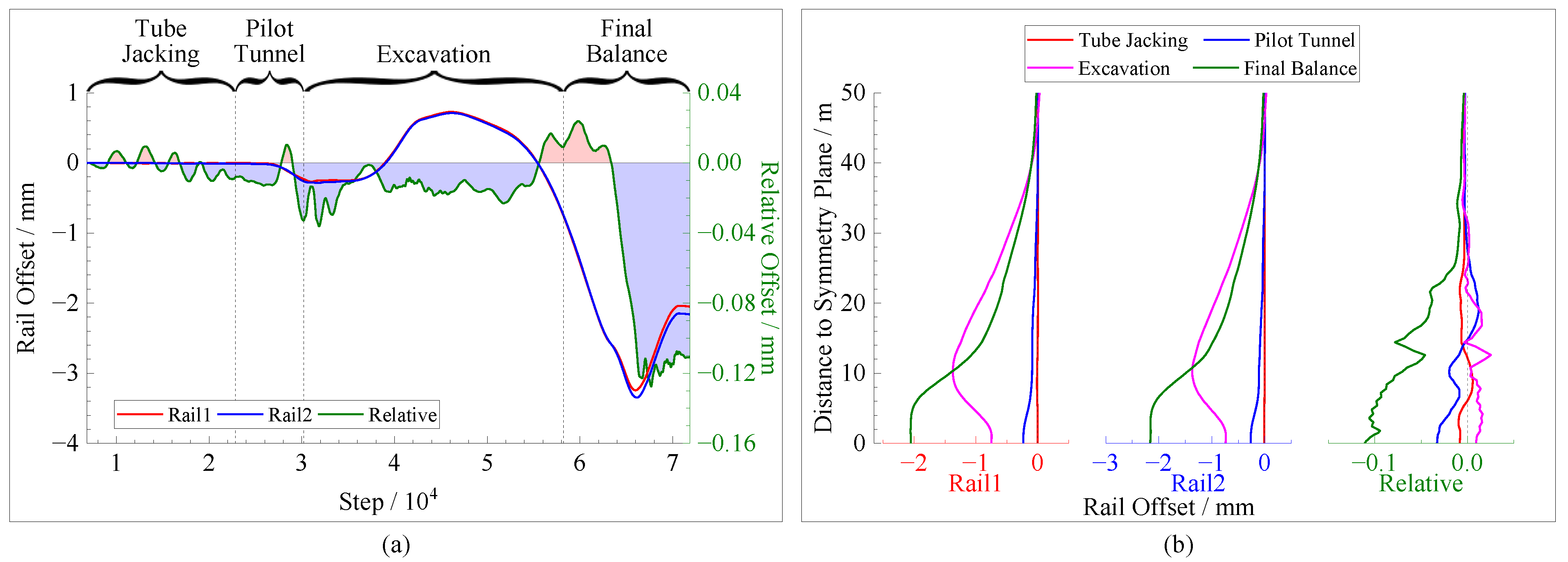
4.3. Case 3
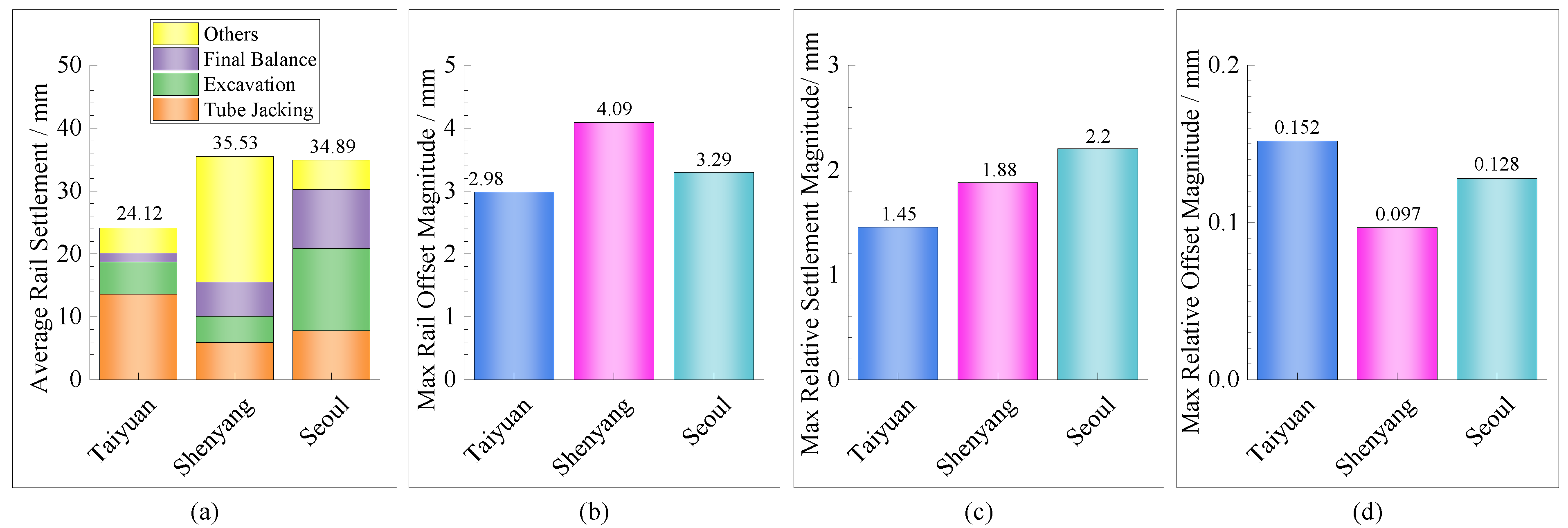
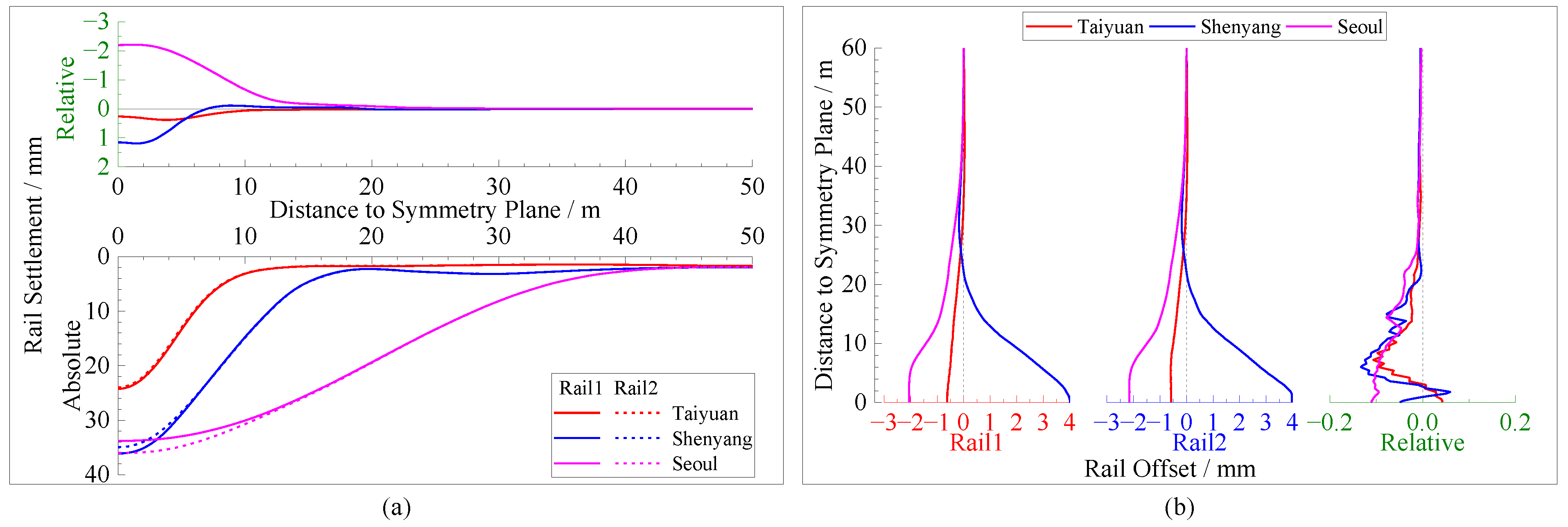
4.4. Comparison of Research Cases
5. Discussion
Author Contributions
Funding
Institutional Review Board Statement
Informed Consent Statement
Data Availability Statement
Acknowledgments
Conflicts of Interest
References
- Sze, Y.S.E.; Yee, T.C.J.; Kim, I.H.; Osborne, N.H.; Chang, K.B.; Siew, R. Tunnelling undercrossing existing live MRT tunnels. Tunn. Undergr. Space Technol. 2016, 57, 241–256. [Google Scholar]
- Zheng, G.; Fan, Q.; Zhang, T.Q. Multistage regulation strategy as a tool to control the vertical displacement of railway tracks placed over the building site of two overlapped shield tunnels. Tunn. Undergr. Space Technol. 2019, 83, 282–290. [Google Scholar] [CrossRef]
- Tonon, F. Sequential excavation, NATM and ADECO: What they have in common and how they differ. Tunn. Undergr. Space Technol. 2010, 25, 245–265. [Google Scholar] [CrossRef]
- Pelizza, S.; Daniele, P. Soil and rock reinforcements in tunnelling. Tunn. Undergr. Space Technol. 1993, 8, 357–372. [Google Scholar] [CrossRef]
- Bougard, J.F. The mechanical pre-cutting method. Tunn. Undergr. Space Technol. 1988, 3, 163–167. [Google Scholar] [CrossRef]
- Yu, L.; Zhang, D.L.; Fang, Q. Surface settlement of subway station construction using pile-beam-arch approach. Tunn. Undergr. Space Technol. 2019, 90, 340–356. [Google Scholar] [CrossRef]
- Sysyn, M.; Przybylowicz, M.; Nabochenko, O. Mechanism of Sleeper–Ballast Dynamic Impact and Residual Settlements Accumulation in Zones with Unsupported Sleepers. Sustainability 2021, 13, 7740. [Google Scholar] [CrossRef]
- Sysyn, M.; Przybylowicz, M.; Nabochenko, O. Identification of Sleeper Support Conditions Using Mechanical Model Supported Data-Driven Approach. Sensors 2021, 21, 3609. [Google Scholar] [CrossRef]
- Musso, G. Jacked pipe provides roof for underground construction in busy urban area. Civ. Eng. 1979, 49, 79–82. [Google Scholar]
- Lunardi, P. The cellular arch method: Technical solution for the construction of the Milan railway’s venezia station. Tunn. Undergr. Space Technol. 1990, 5, 351–356. [Google Scholar] [CrossRef]
- Lee, Y.B.; Kim, J.Y.; Park, I.J. A study on the applicability of underground structure using steel tubular roof in Korean geotechnical condition. J. Korean Tunn. Undergr. Space Assn. 2003, 5, 401–409. [Google Scholar]
- Jeon, H.T.; Kim, Y.H.; Kim, S.K. The construction of Lot 923 subway station using the trenchless TRCM (Tubular Roof Construction Method). Harmon. Nat. Civiliz. 2007, 55, 39–47. [Google Scholar]
- Yang, X.; Li, Y.S. Research of surface settlement for a single arch long-span subway station using the Pipe-roof Pre-construction Method. Tunn. Undergr. Space Technol. 2018, 72, 210–217. [Google Scholar] [CrossRef]
- Ba, F.; Chen, J.; Shi, H.Q. Performance of new tubular roof construction method—A 3D numerical investigation. In Proceedings of the 2018 International Conference on Engineering Simulation and Intelligent Control (ESAIC), Hunan, China, 10–11 August 2018. [Google Scholar]
- Lei, S.X.; Ding, Z.Q.; Li, X.D. Simulation analysis of influences of tunnel construction using new tubular roof method. J. Nanjing Inst. Technol. (Nat. Sci. Ed.) 2021, 19, 24–28. [Google Scholar]
- Xiao, D.D. Study on the Tunnel Structural Design and Construction Mechanics Effect of the New Tubular Roof Method on the TaiYuan Railway Station. Master’s Thesis, Shijiazhuang Tiedao University, Shijiazhuang, China, 2022. [Google Scholar]
- Liu, W.Y. Research on Influencing Factors of Surface Subsidence and Control Technology in Construction of New Tubular Roof Method. Master’s Thesis, Shandong University of Science and Technology, Qingdao, China, 2020. [Google Scholar]
- Ren, G.F.; Yang, X.C.; Zhang, C.R. On the ground subsidence monitoring in the construction of the currently existing rail-lines under the new tube curtain method. J. Saf. Envir. 2021, 21, 163–171. [Google Scholar]
- TB 10082-2017; Code for Design of Railway Track. China Railway Publishing House Co., Ltd.: Beijing, China, 2017.
- Roscoe, K.H.; Burland, J.B. On the Generalised Stress-Strain Behavior of ‘Wet Clay’. In Engineering Plasticity; Heyman, J., Leckie, F.A., Eds.; Cambridge University Press: Cambridge, UK, 1968; pp. 535–609. [Google Scholar]
- Mei, Y.; Hu, C.M.; Yuan, Y.L. Experimental study on deformation and strength property of compacted loess. Geomech. Eng. 2016, 11, 161–175. [Google Scholar] [CrossRef]
- Wen, B.P.; Yan, Y.J. Influence of structure on shear characteristics of the unsaturated loess in Lanzhou, China. Eng. Geol. 2014, 168, 46–58. [Google Scholar] [CrossRef]
- Shi, J.K.; Zhang, W.Y.; Feng, Y.Z. Triaxial test and numerical simulation of undisturbed loess in Xining area. J. Qinghai Univ. 2020, 38, 66–71. [Google Scholar]
- Yang, X.Q.; Gao, Z.Y.; Sui, J. Consolidated undrained shear tests of Qingyang unsaturated undisturbed loess soil samples. Soil Eng. Found. 2021, 35, 787–791. [Google Scholar]
- Zhang, Y.; Sui, J.; Lin, C.X. Consolidation, dilation and yield characteristics of unsaturated undisturbed loess in Qingyang. Rock Soil Mech. 2020, 41, 1–10. [Google Scholar]
- Lou, G.C. Study on the Settlement and Controlling Criteria of Existing Embankment during Railway Tunnel Construction Underpassing by Conventional Method. Ph.D. Thesis, Beijing Jiaotong University, Beijing, China, 2012. [Google Scholar]
- TB/T 3276-2011; Rails for High Speed Railway. China Railway Publishing House Co., Ltd.: Beijing, China, 2011.


| Geochronology | No. | Type | Color | Status | Composition | Layer Thickness/m |
|---|---|---|---|---|---|---|
| Q4 ml | 1-1 | Miscellaneous fill | Grey | Loose~ Slightly dense | Construction waste, gravel, loess clay | 1.5~15.4 |
| 1-2 | Plain fill | Tan | Loose~ Slightly dense | Gravel, loess clay | 4.0~9.6 | |
| Q4 al + pl | 2-1 | Loess | Tan | High plasticity | Loess clay, ginger stone, a small amount of white mycelium | 3.5~15.9 |
| 2-2 | Loess | Tan | Low plasticity | Loess clay, ginger stone, a small amount of white mycelium | 29.9(Not explored to the bottom) |
| Parameter | Description/Unit | Value | |||
|---|---|---|---|---|---|
| Subgrade | Fill Stratum | Loess (2-1) | Loess (2-2) | ||
| t | Thickness of layer/m | 2.4 | 6.05 | 8.25 | 87 |
| ρ | Density/kg·m−3 | 1900 | 1600 | 1700 | 1780 |
| ν | Poisson’s ratio | 0.3 | 0.38 | 0.38 | 0.3 |
| φ | Friction angle/° | 20 | 15 | 18.03 | 16.32 |
| cu | Undrained shear strength/kPa | 35 * | 13.03 | 42.26 | 48.49 |
| Cc | Compression index | 0.09 * | 0.18 * | 0.138 | 0.115 |
| Cs | Swelling index | 0.01 * | 0.009 * | 0.0069 | 0.0053 |
| e0 | Natural void ratio | 0.75 * | 0.93 | 0.63 | 0.63 |
| OCR | Over consolidation ratio | 1.5 * | 1 * | 1 * | 1 * |
| p1 | Reference pressure/MPa | 0.1 | |||
| Parameter | Description/Unit | Value | ||
|---|---|---|---|---|
| Steel | Concrete | Grouted Soil | ||
| ρ | Density/kg·m−3 | 7850 | 2300 | 2000 |
| E | Young’s modulus/GPa | 206 | 34.5 | 10 |
| ν | Poisson’s ratio | 0.3 | 0.2 | 0.2 |
| Parameter | Description/Unit | Value | |||||
|---|---|---|---|---|---|---|---|
| Main Rail | Buckle Rail (Middle) | Buckle Rail (Side) | Pile Shed | Inner Support | Bolt | ||
| A | Cross-sectional area/cm2 | 77.45 | 329 | 197.4 | 254.5 | 15.48 | 4.9 |
| Iy | Moment of inertia alone the main bending direction/cm4 | 3217 | 10,185 | 6111 | 7490 | 232.4 | / |
| Iz | Moment of inertia perpendicular to the main bending direction/m4 | 524 | 29,039 | 6109 | 7490 | 232.4 | / |
| Iρ | Polar moment of inertia/m4 | 3741 | 39,224 | 12,220 | 14,980 | 464.8 | / |
| Boundary Direction | Boundary Type | Degree of Freedom | |||||
|---|---|---|---|---|---|---|---|
| X | Y | Z | XR | YR | ZR | ||
| X-Positive | Infinity field boundary | fix | - | - | - | - | - |
| X-Negative | Symmetry plane | fix | - | - | - | fix | fix |
| Y-Positive | Semi-rigid wall | Fix * | fix | fix * | - | - | - |
| Y-Negative | Semi-rigid wall | Fix * | fix | fix * | - | - | - |
| Z-Positive | Free surface | - | - | - | - | - | - |
| Z-Negative | Infinity field boundary | fix | fix | fix | - | - | - |
| Method | Advantages | Disadvantages |
|---|---|---|
| “Taiyuan method” |
|
|
| “Shenyang method” |
|
|
| “Seoul method” |
|
|
Publisher’s Note: MDPI stays neutral with regard to jurisdictional claims in published maps and institutional affiliations. |
© 2022 by the authors. Licensee MDPI, Basel, Switzerland. This article is an open access article distributed under the terms and conditions of the Creative Commons Attribution (CC BY) license (https://creativecommons.org/licenses/by/4.0/).
Share and Cite
Li, X.; Tan, Z.; Wang, X.; Lei, K. Comparative Study on the Influence of Different Forms of New Tubular Roof Method Construction on Railway Tracks. Symmetry 2022, 14, 1361. https://doi.org/10.3390/sym14071361
Li X, Tan Z, Wang X, Lei K. Comparative Study on the Influence of Different Forms of New Tubular Roof Method Construction on Railway Tracks. Symmetry. 2022; 14(7):1361. https://doi.org/10.3390/sym14071361
Chicago/Turabian StyleLi, Xiaoxue, Zhongsheng Tan, Xiuying Wang, and Ke Lei. 2022. "Comparative Study on the Influence of Different Forms of New Tubular Roof Method Construction on Railway Tracks" Symmetry 14, no. 7: 1361. https://doi.org/10.3390/sym14071361
APA StyleLi, X., Tan, Z., Wang, X., & Lei, K. (2022). Comparative Study on the Influence of Different Forms of New Tubular Roof Method Construction on Railway Tracks. Symmetry, 14(7), 1361. https://doi.org/10.3390/sym14071361