
Inductance Analysis of Two-Phase Winding Segmented Permanent Magnet Linear Synchronous Motor


Abstract
:1. Introduction
- The WS-PMLSM has an offset pulsating magnetic field [8] due to the adjacent segment cores, which will cause the magnetic field at the yoke near the energized segment to saturate easily and the inductance of the motor will be unbalanced, which will make the inductance and position in the -based algorithm not decoupled and a sinusoidal function will appear in the equation [9].
- During motor operation, when the mover overlaps with parts of two or three stator segments, the inductance variation of the stator contains multiple harmonics, this will produce a position-dependent inverse electric potential (EMF) constant [10].
- The current in the transition section must have the same amplitude and phase [11].
- The current of the transition section should adopt the “master-slave” follow mode [12].
- Transitional inductance should be solved by a look-up table method [13].
- Thrust fluctuation adopts feedforward or online identification iteration, disturbance observer [3].
- Optimal control with consistent energy consumption and thrusts [14].
2. Motor Model
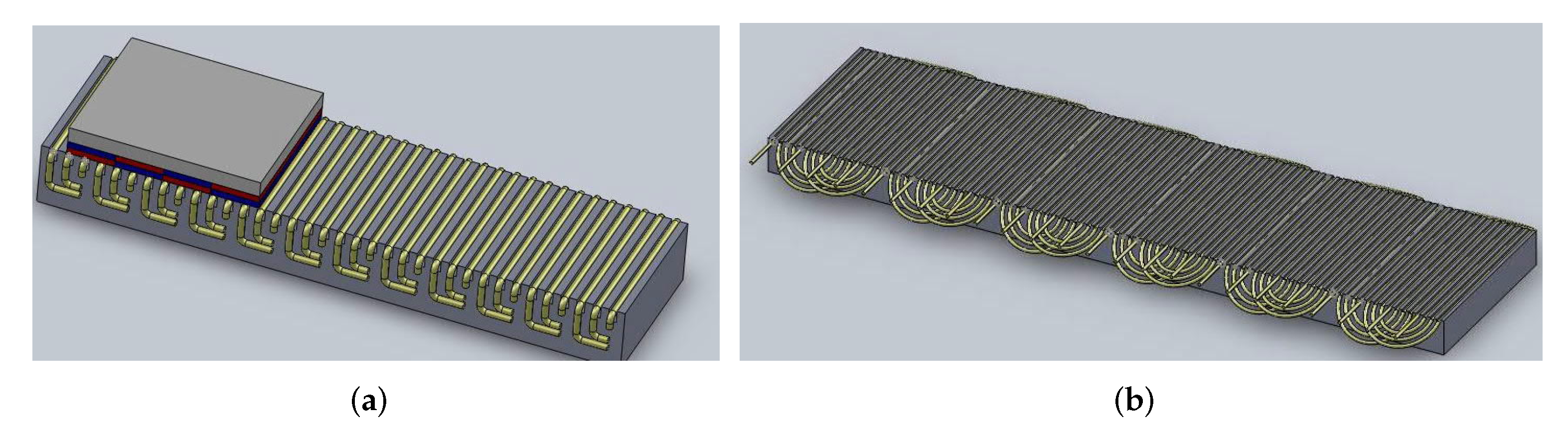
- The two-phase motor is phase-balanced because the magnetic circuit is the same in each phase. Therefore, it eliminates the phase asymmetry problem caused by half-filled slots, which is common in three-phase linear motors.
- Although motors with two-phase windings are not advantageous in the design of rotary motors, the advantages of two-phase windings are obvious in linear motors, the span of the winding is smaller than that of the three-phase, the two windings are spatially perpendicular to each other, there are no Clark and anti-Clark transformations, the speed of vector control implementation is accelerated, and the general embedded system can meet the requirements.
- The two-phase winding can be easily made into a single layer winding, and since only one winding is embedded in each stator slot along the active side of the coil, the inductance is basically physically balanced, which also makes the process simple, the full slot rate high, and the windings can be made in concentric mode to achieve the physical structure of a sinusoidal winding and reduce harmonics.
3. Inductance and WS-PMLSM Control
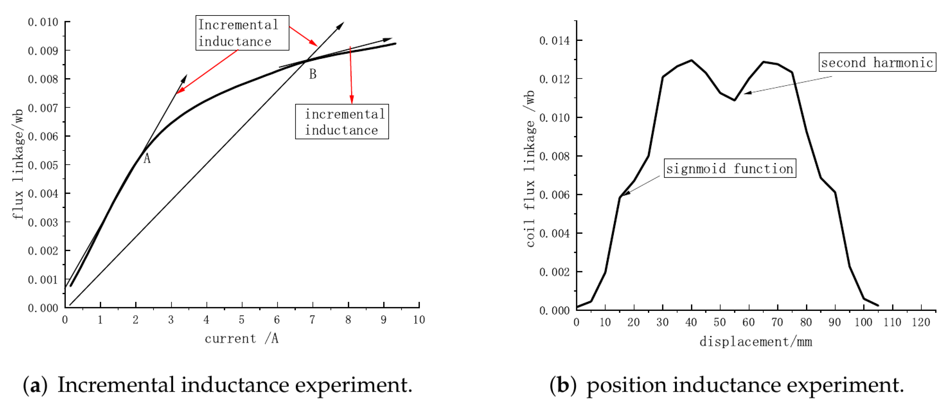
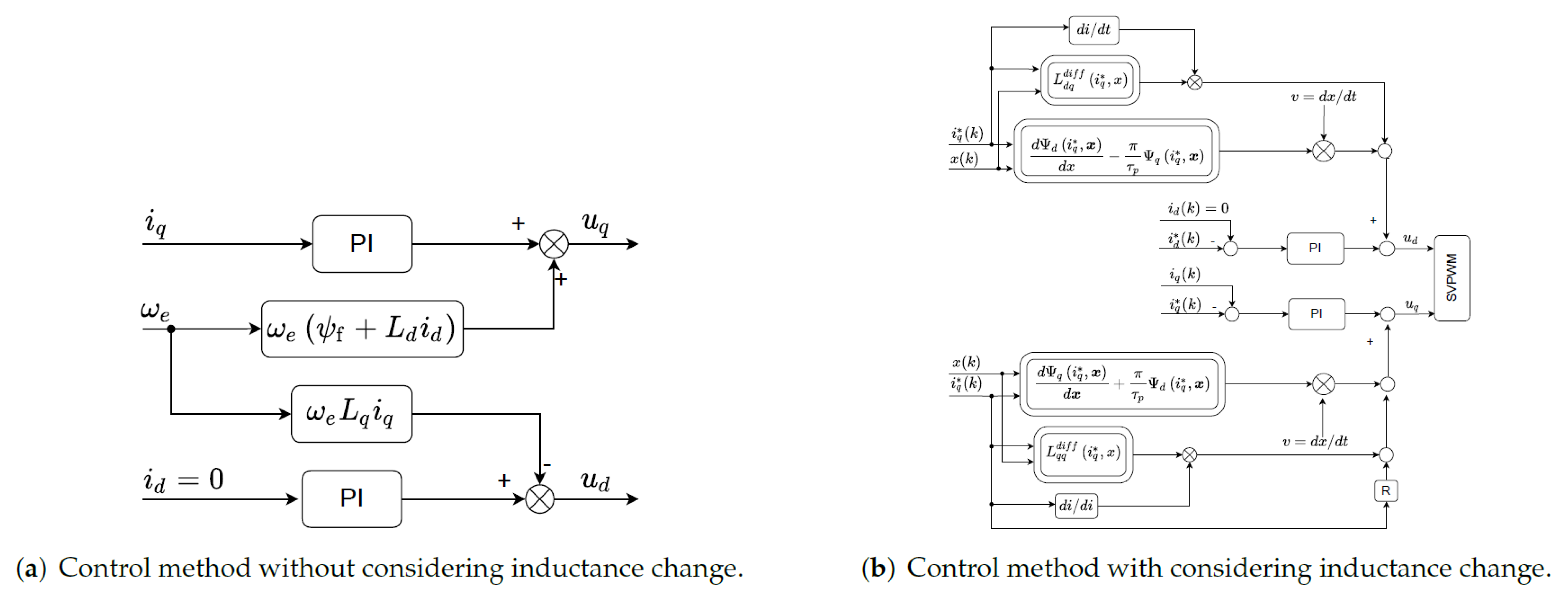
- The inductance becomes an inductance matrix-, also known as the differential inductance array, which consists of apparent inductance and incremental inductance.
- The apparent inductance-, is a constant in conventional motor, but in the WS-PMLSM, it is a function of position and current.
- In Equation (13), the differential inductance minus the apparent inductance is the incremental inductance, which can be ignored in the linear motor
- indicates the variation of inductance with position, which can generally be obtained by curve fitting.
4. Apparent Inductance of Motor
4.1. Motor Winding
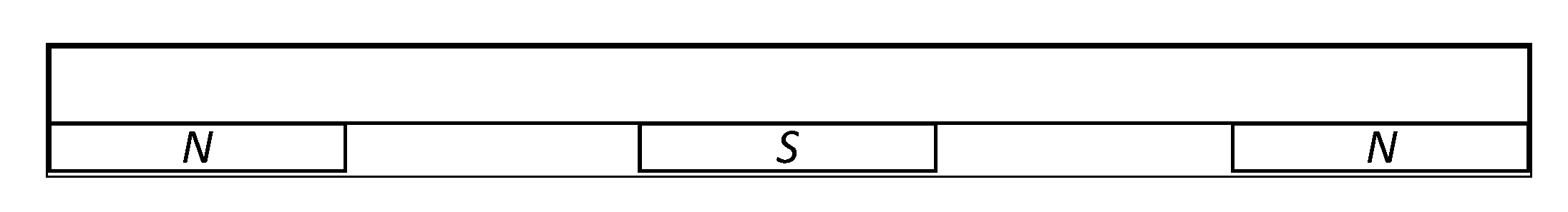
4.2. Motor Magnets
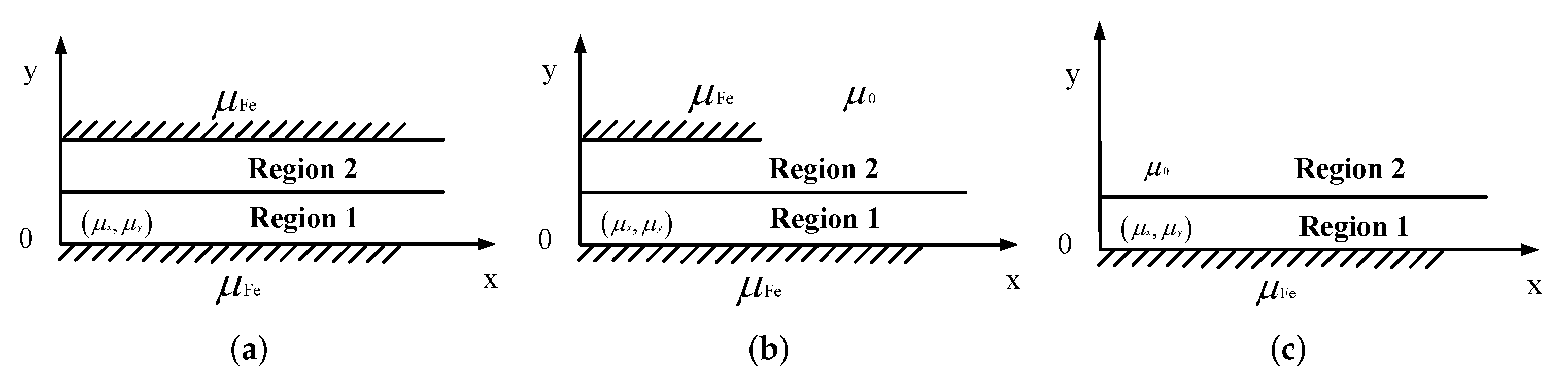
4.3. Flux Analysis
4.3.1. Dynamic Processes
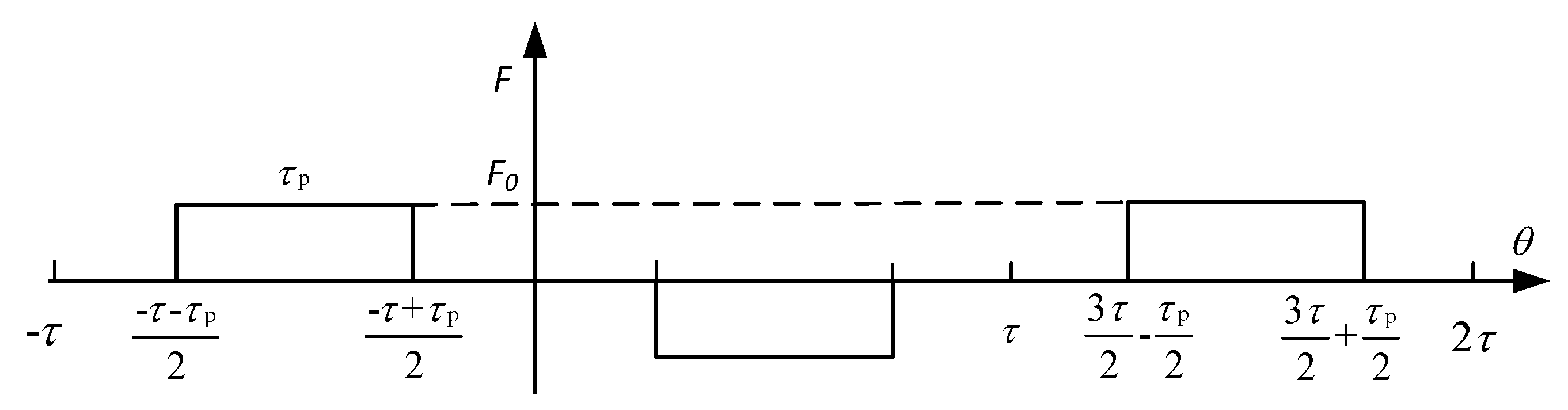
4.3.2. Analysis of Air Gap Permeability Coefficient
4.3.3. Inductance of Motor
5. Incremental Inductance Analysis of WS-PMLSM
6. Experimental Analysis
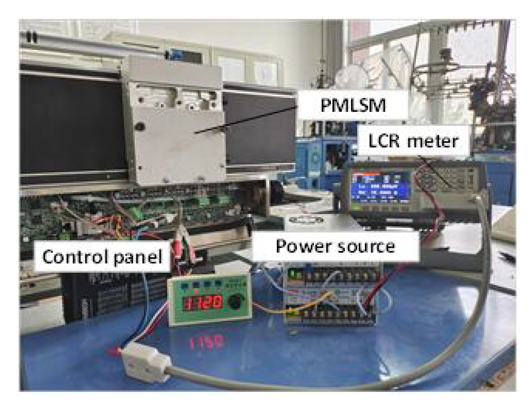
6.1. Experimental Methods and Equipment
- (1)
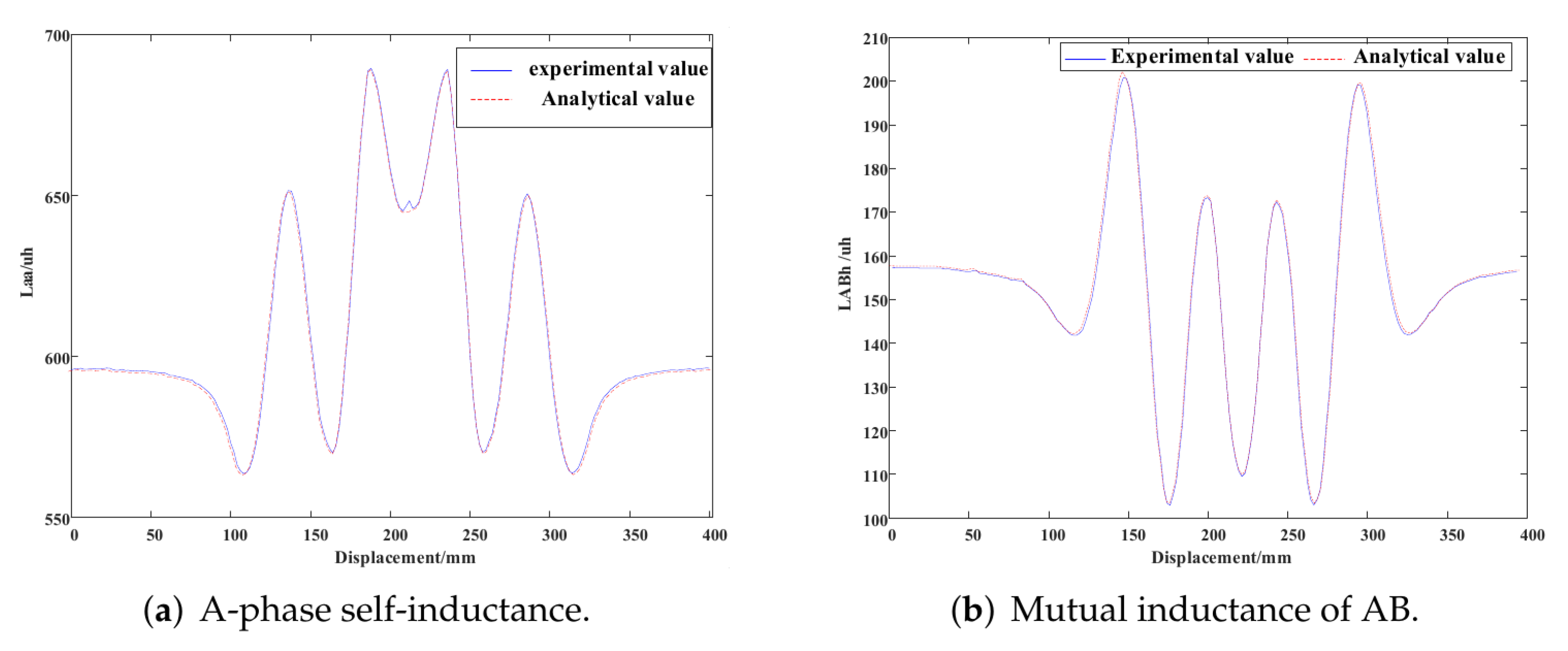
- The apparent inductance is measured using the conventional method of direct measurement of the self-inductance of the A and B phase windings using the LCR digital bridge.
- (2)
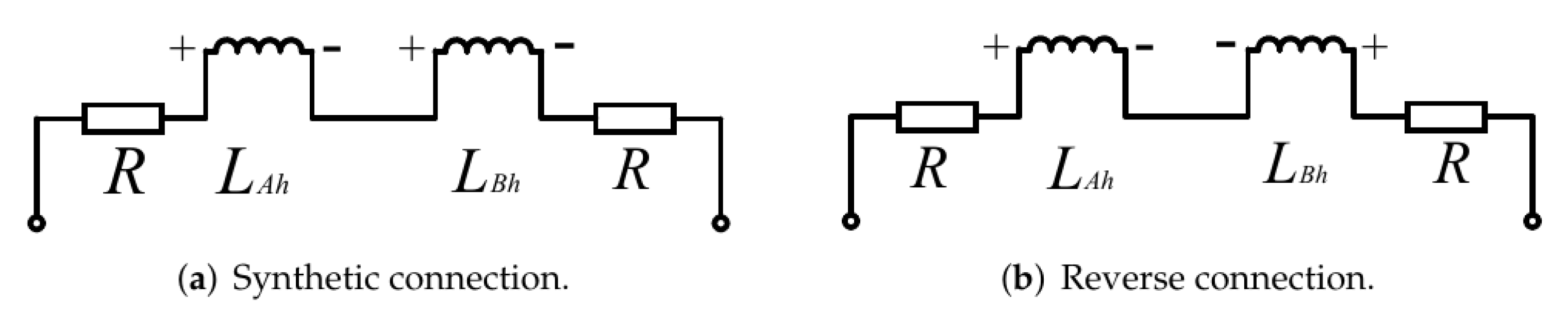
- The mutual inductance of the A and B phase windings of the apparent inductor is accomplished by changing the circuit, i.e., when measuring the mutual inductance, the connection of the A and B phase windings needs to be changed, as shown in Figure 10, when the two windings are connected in the same direction, the equivalent inductance expression is , when the two windings are connected in reverse, the equivalent inductance expression is: , so, the mutual inductance of AB two-phase winding can be obtained by combining .Since the operation of LCR is relatively simple, we will not expand the description here, but we should pay attention to the selection of test frequency during the test. If the frequency is selected too high, the capacitive characteristics of the motor coil will be prominent and affect the inductance measurement results. In this paper, the test frequency is selected as 120 Hz.
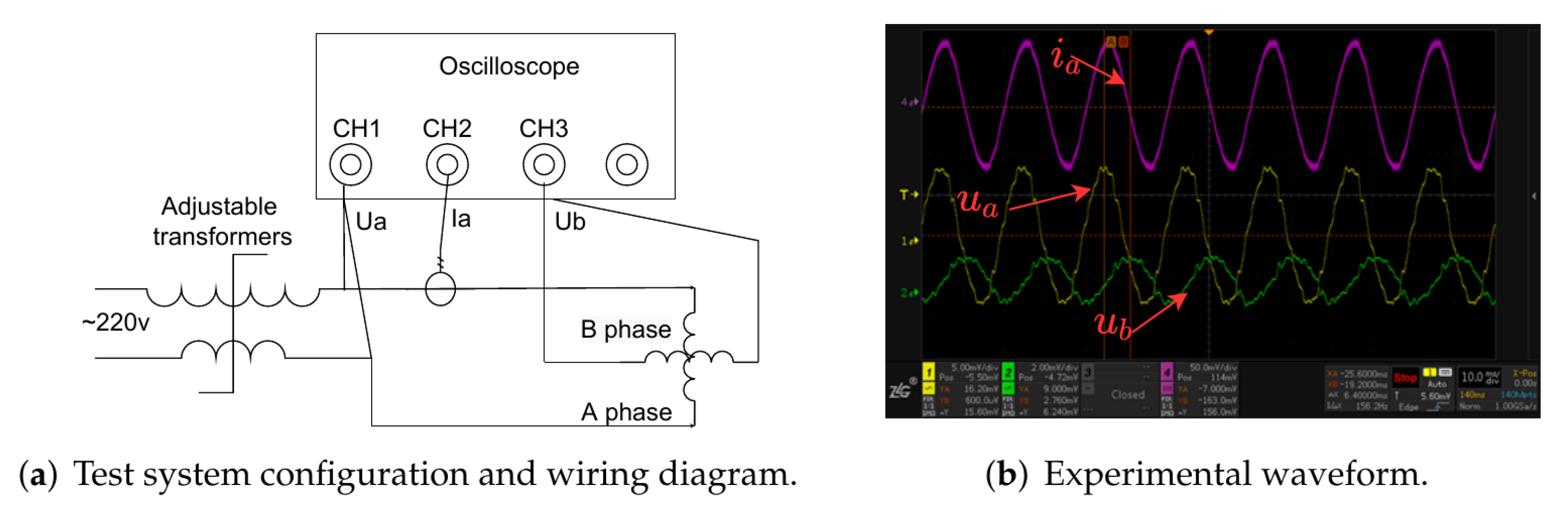
- (3)
- The incremental inductance is measured by the current differentiation method (). The segmented motor studied in this paper uses a surface-mounted permanent magnet structure, and the conductivity of the permanent magnet material is so small that the B phase can be open-circuited when the A phase is in the test state, so the measurement conditions are met, and vice versa.
6.2. Experimental Results
7. Conclusions
- (1)
- The second harmonic of the self-inductance of the two-phase winding designed in this paper is very small, and the higher harmonics are even less.
- (2)
- In the fully coupled state, the amplitude ratio of the DC components of mutual inductance and self-inductance of the A and B phase windings is unchanged, and the mutual inductance is one-third of the self-inductance, and the mutual inductance under the -axis is basically zero, and the vector control with general feedforward can be used for occasions with low requirements.
- (3)
- In the full travel range, the DC components of the self and mutual inductance of the A and B phase windings with the second harmonic amplitude decrease as the motor coupling length decreases, which is basically linear, unlike the motor with three-phase winding.
- (4)
- Inductance is available in two cases viz: and , consisting of apparent inductance and incremental inductance, in the linear region, they are equal, but in the saturation region, they are not equal, so it is necessary to take a reasonable way in high acceleration and deceleration control, is basically a constant.
- (5)
- The role of inductance in different controls is different, so pay attention to the trade-offs.
Author Contributions
Funding
Institutional Review Board Statement
Informed Consent Statement
Data Availability Statement
Conflicts of Interest
References
- Rassudov, L.; Tolstikh, O.; Tiapkin, M.; Paskalov, N.; Korunets, A.; Osipov, D. Digital Twin Implementation for Accelerating the Development of Flexible Transportation System Control Software. In Proceedings of the 2021 IEEE 62nd International Scientific Conference on Power and Electrical Engineering of Riga Technical University (RTUCON), Riga, Latvia, 15 November 2021; pp. 1–4. [Google Scholar] [CrossRef]
- Zhang, T.; Du, X.; Mei, X. Modelling and Analysis of Two-Phase Winding Segmented Permanent Magnet Linear Synchronous Motor. In Proceedings of the 2021 13th International Symposium on Linear Drives for Industry Applications (LDIA), Wuhan, China, 1–3 July 2021; pp. 1–6. [Google Scholar] [CrossRef]
- Benavides, R.; Mutschler, P. Detent force compensation in segmented long stator permanent magnet linear drives using Finite Element Models. In Proceedings of the 2007 European Conference on Power Electronics and Applications, Aalborg, Denmark, 2–5 September 2007; pp. 1–10. [Google Scholar]
- Mutschler, P. Comparison of topologies for linear drives in industrial material handling and processing applications. In Proceedings of the 2007 7th Internatonal Conference on Power Electronics, Aalborg, Denmark, 2–5 September 2007; pp. 1027–1032. [Google Scholar]
- Rovers, J.; Jansen, J.; Lomonova, E. Novel force ripple eduction method for a moving-magnet linear synchronous motor with a segmented stator. In Proceedings of the 2008 International Conference on Electrical Machines and Systems, Wuhan, China, 17–20 October 2008; pp. 2942–2947. [Google Scholar]
- Benavides Oswald, R. Investigation of Control Methods for Segmented Long Stator Linear Drives. Ph.D. Thesis, Technische Universität, Darmstadt, Germany, 2008. [Google Scholar]
- Hall, D.; Kapinski, J.; Krefta, M.; Christianson, O. Transient electromechanical modeling for short secondary linear induction machines. IEEE Trans. Energy Convers. 2008, 23, 789–795. [Google Scholar] [CrossRef]
- Tan, Q.; Wang, M.; Li, L.; Li, J. Pulsating magnetic field of permanent magnet linear synchronous motor and its influence on detent force. IEEE Trans. Energy Convers. 2020, 36, 703–712. [Google Scholar] [CrossRef]
- Lu, Q.; Wu, B.; Yao, Y.; Shen, Y.; Jiang, Q. Analytical model of permanent magnet linear synchronous machines considering end effect and slotting effect. IEEE Trans. Energy Convers. 2019, 35, 139–148. [Google Scholar] [CrossRef]
- Cui, L.; Zhang, H.; Jiang, D. Research on High Efficiency V/f Control of Segment Winding Permanent Magnet Linear Synchronous Motor. IEEE Access 2019, 7, 138904–138914. [Google Scholar] [CrossRef]
- Wang, M.; Kang, K.; Zhang, C.; Li, L. A Driver and Control Method for Primary Stator Discontinuous Segmented-PMLSM. Symmetry 2021, 13, 2216. [Google Scholar] [CrossRef]
- Junjie, H.; Donghua, P.; Zhijian, Z. Comparison of the two current predictive-control methods for a segment-winding permanent-magnet linear synchronous motor. IEEE Trans. Plasma Sci. 2013, 41, 1167–1173. [Google Scholar]
- Queval, L.; Ohsaki, H. Nonlinear abc-model for electrical machines using N-D lookup tables. IEEE Trans. Energy Convers. 2014, 30, 316–322. [Google Scholar] [CrossRef]
- Perreault, B.M. Optimizing operation of segmented stator linear synchronous motors. Proc. IEEE 2009, 97, 1777–1785. [Google Scholar] [CrossRef]
- Molano, J.C.C.; Capelli, L.; Rubini, R.; Borghi, D.; Cocconcelli, M. A bearing fault model for Independent Cart Conveyor System and its validation. Appl. Acoust. 2020, 159, 107069. [Google Scholar] [CrossRef]
- Zhu, Z.; Howe, D.; Mitchell, J. Magnetic field analysis and inductances of brushless DC machines with surface-mounted magnets and non-overlapping stator windings. IEEE Trans. Magn. 1995, 31, 2115–2118. [Google Scholar] [CrossRef]
- Wang, J.; Jewell, G.W.; Howe, D. A general framework for the analysis and design of tubular linear permanent magnet machines. IEEE Trans. Magn. 1999, 35, 1986–2000. [Google Scholar] [CrossRef] [Green Version]
- Chiba, A.; Nakamura, F.; Fukao, T.; Rahman, M.A. Inductances of cageless reluctance-synchronous machines having nonsinusoidal space distributions. IEEE Trans. Ind. Appl. 1991, 27, 44–51. [Google Scholar] [CrossRef]
- Dutta, R.; Rahman, M.; Chong, L. Winding inductances of an interior permanent magnet (IPM) machine with fractional slot concentrated winding. IEEE Trans. Magn. 2012, 48, 4842–4849. [Google Scholar] [CrossRef]
- Liu, C.; Wang, H.; Zhang, Z.; Shen, X. Research on thrust characteristics in permanent magnet linear synchronous motor based on analysis of nonlinear inductance. Proc. CSEE 2011, 30, 69–76. [Google Scholar]
- Jikun, Y.; Liyi, L.; Jiangpeng, Z. Analytical calculation of air-gap relative permeance in slotted permanent magnet synchronous motor. Trans. China Electrotech. Soc. 2016, 31, 45–52. [Google Scholar]
- Liyi, L.; Mingna, M.; Jiaxi, L.; Chan, C. Inductance analysis in pass-through section for multi-segmented permanent magnet linear motors based on magnetic energy perturbation. Trans. China Electrotech. Soc. 2013, 28, 46–55. [Google Scholar]
- Zhang, H.; Chen, G.; Zhang, K. Analytical calculation of Permanent Magnet Flux Linkage and Winding Inductance of Mover Permanent Magnet Double Salient Reluctance Linear Machines. In Proceedings of the 2021 IEEE 4th Student Conference on Electric Machines and Systems (SCEMS), Hangzhou, China, 1–3 December 2021; pp. 1–7. [Google Scholar]
- Shujun, M.; Jianyun, C.; Xudong, S.; Shanming, W. Analysis and Restrain of Mutual Inductance Asymmetry in the Sectionally Powered AC Linear Motor. Trans. China Electro Tech. Soc. 2015, 30, 81–88. [Google Scholar]
- Ma, M.; Li, L.; Zhang, J.; Yu, J.; Zhang, H. Investigation of cross-coupling inductances for long-stator PM linear motor arranged in multiple segments. IEEE Trans. Magn. 2015, 51, 1–4. [Google Scholar]


| Description | Symbol | Value | Unit |
|---|---|---|---|
| Length of segmented stator | 2 | 100 | |
| Pitch of permanent magnet | 50 | ||
| Pitch of coil | 50 | ||
| Turn of coil | n | 10 | |
| Resistance of coil | 2.55 | ||
| Inductance of coil | 16.9 | ||
| Number of poles | 2.3 | any combination | |
| Connection pattern | star/tri | any combination | |
| Stator materials | 35JN470 | ||
| Magnet materials | 35SH | ||
| Magnet residual magnetic | 1.15 | T | |
| Magnet coercive force | 1672 | KA/m | |
| Mover yoke materials | 35JN470 |
| Mover Position | ||
|---|---|---|
| Mover Position | ||
|---|---|---|
Publisher’s Note: MDPI stays neutral with regard to jurisdictional claims in published maps and institutional affiliations. |
© 2022 by the authors. Licensee MDPI, Basel, Switzerland. This article is an open access article distributed under the terms and conditions of the Creative Commons Attribution (CC BY) license (https://creativecommons.org/licenses/by/4.0/).
Share and Cite
Zhang, T.; Mei, X. Inductance Analysis of Two-Phase Winding Segmented Permanent Magnet Linear Synchronous Motor. Symmetry 2022, 14, 1180. https://doi.org/10.3390/sym14061180
Zhang T, Mei X. Inductance Analysis of Two-Phase Winding Segmented Permanent Magnet Linear Synchronous Motor. Symmetry. 2022; 14(6):1180. https://doi.org/10.3390/sym14061180
Chicago/Turabian StyleZhang, Tuanshan, and Xuesong Mei. 2022. "Inductance Analysis of Two-Phase Winding Segmented Permanent Magnet Linear Synchronous Motor" Symmetry 14, no. 6: 1180. https://doi.org/10.3390/sym14061180
APA StyleZhang, T., & Mei, X. (2022). Inductance Analysis of Two-Phase Winding Segmented Permanent Magnet Linear Synchronous Motor. Symmetry, 14(6), 1180. https://doi.org/10.3390/sym14061180