Article

Joint Security and Energy-Efficient Cooperative Architecture for 5G Underlaying Cellular Networks

1
School of Computer Science and Engineering, Northeastern University, Shenyang 110819, China
2
School of Software, Northeastern University, Shenyang 110819, China
3
Department of Electronic and Information Engineering, The Hong Kong Polytechnic University, Hong Kong 999077, China
*
Author to whom correspondence should be addressed.
Symmetry 2022, 14(6), 1160; https://doi.org/10.3390/sym14061160
Submission received: 26 April 2022 / Revised: 28 May 2022 / Accepted: 31 May 2022 / Published: 4 June 2022
(This article belongs to the Section Computer)

Abstract

:
Device-to-device (D2D) communication is a promising technology which can improve the spectrum efficiency of cellular networks. Despite abundant research on resource allocation and interference cancellation for D2D communication, few works discuss how D2D is realized within cellular communication. In this paper, we propose a symmetric cooperative communication architecture combining security and energy efficiency, in which the users in 5G cellular networks can adaptively select the communication mode among cellular, direct D2D, and relay-assisted D2D communication according to the energy-consumption requirement. Considering the security aspect, we propose a novel relay selection strategy based on the asymmetry of social networks for the architecture. Firstly, we reduce the number of candidate relay devices based on energy consumption, the devices’ battery status, and the devices’ state. Then, an appropriate relay device is selected according to the proposed criteria, combining energy consumption, wireless channel quality, proximity prestige, and spreading ability. Simulation results reveal that, compared with conventional cellular communication and D2D communication, the proposed architecture can increase the number of users accessing the cellular networks simultaneously, improving the throughput and the security of data transmission. It can also significantly reduce the energy consumption as well as outage probability.

1. Introduction

With the streaming of high-resolution video and the increasing market penetration of intelligent mobile terminal equipment, the data traffic carried by the mobile communication network has been explosively increasing in recent years. According to a forecast in [1], global mobile data traffic will increase sevenfold between 2016 and 2021 and the number of devices connected to Internet Protocol (IP) networks will reach tens of billions. The remarkable growth momentum promotes the development of the next generation of mobile communication (5G) [2,3,4,5]. However, the huge mobile data traffic has posed great challenges to the system and architecture of existing communication networks. The problem between the explosive growth of mobile traffic and the shortage of spectrum resources has become increasingly apparent. Researchers try to mitigate the issue by redistributing the spectrum resources [6,7,8], although this cannot fundamentally solve the problem. Therefore, a new communication strategy which can improve the user experience is urgently needed for 5G. Device-to-device (D2D) communication [9,10,11,12,13,14,15], one of the key technologies of 5G, has been included in the development framework of 5G by the 3rd Generation Partnership Project (3GPP).
D2D is defined as a direct communication between two mobiles without the aid of a typical cellular base station (BS) and was originally proposed in [16]. In [16], Lin and Hsu presented a new architecture called Multihop Cellular Network (MCN) for wireless communications. It can be regarded as the origin of D2D technology. Through the research on D2D in recent few years, the advantages of D2D technology are more readily apparent [17,18,19,20]. D2D can greatly improve spectrum efficiency, typical user speed, capacity per unit area, coverage area of wireless signals, power efficiency, and transmission delay. It is also conducive to low-delay communication through local communication links in adjacent areas. D2D is an indispensable technology for real-time service of a 5G system because it can increase diversity gain, improve system reliability, and significantly reduce power consumption.

1.1. Related Literatures

In academia, abundant research on D2D has appeared very recently. The majority of available literature on D2D communication is dedicated to efficient D2D discovery [21,22,23], resource allocation between D2D and cellular communication [24,25,26,27], as well as the interference between D2D and cellular communication [28,29,30,31].
The device discovery process is a key enabler for D2D communication. In [21], Tang et al. proposed several neighbor discovery methods through joint neighbor detection and D2D channel estimation. In these methods, a framework of block sparse Bayesian learning is equipped to discover devices accurately. However, the methods proposed in [21] could induce high energy consumption. Therefore, in order to save energy, an efficient D2D discovery mechanism where the users activate their D2D capabilities only when there is a high probability to be involved in the proximity of other users was investigated in [22].
In practice, D2D can be divided into inband D2D and outband D2D. To improve the spectrum efficiency of cellular networks, the majority of research on D2D is dedicated to inband D2D, especially D2D communication underlaying cellular networks, in which D2D and cellular communications share the same spectrum resources. Resource allocation and interference cancellation are the two most important issues in underlaying D2D communications. To solve this problem, Feng et al. [24] proposed a three-step resource-allocation scheme to maximize the overall network throughput. At the same time, the QoS requirements for D2D users and cellular users would also be guaranteed. Different from the target in [24], an energy-efficient stable matching algorithm for the resource allocation problem in D2D communication was described in [26]. Similarly, Dun et al. [27] proposed a FD relaying scheme for D2D communication in which the optimal transmit power and power split factor is derived in a closed form to fulfill the rate requirement of the cellular user and to maximize the achievable rates for D2D link simultaneously.
An excellent interference management algorithm can improve the throughput of the cellular networks. For instance, in [28], two interference avoidance mechanisms were proposed to help the D2D communication to reuse resources intelligently. One is to mitigate the interference caused by cellular communication using an interference tracing approach, and the other is to reduce the interference caused by D2D using a tolerable interference broadcasting approach. Different from [28], another two strategies to handle the interference were introduced in [30]: interference nulling and interference constraining. In [31], a unified treatment of improving spatial reuse and controlling the interference between cellular users and D2D users is presented.
In addition to the aforementioned research, relay-assisted D2D communication [32,33,34] is another research focus which can improve the network service quality. For instance, in [34], Gui et al. analyzed the challenges of relay-aided underlay D2D communication in details, and proposed a scheme which can be divided into relaying channel preallocation, transmit power adjustment, and data receiving mode selection to improve cellular coverage quality. As a major feature of D2D communication, cooperative communication needs to balance various performance of the network. Energy consumption, security [19,35,36] and reliability are the key problems that should be considered. Consequently, we develop a joint security and energy-efficient cooperative architecture for 5G networks.

1.2. Contributions and Paper Organization

In this paper, we focus on the cooperative D2D communication for 5G underlaying cellular networks. Taking energy consumption, security, and outage probability into consideration, we propose a symmetric cooperative communication architecture combining security and energy efficiency. Moreover, a social network-based relay selection scheme for the relay-assisted D2D communication is considered. Our contributions are listed as follows.
  • “Low Battery” is a major factor affecting the user’s experience and the energy consumption should be controlled. As a consequence, we design an adaptive cooperative communication architecture for 5G underlaying cellular networks where users in the network can adaptively select a mode among “cellular communication, direct D2D communication and relay-assisted D2D communication” according to its energy consumption requirement.
  • Considering the asymmetry of the real social network, the proximity prestige and spreading ability are taken into consideration to improve the security of data transmission.
  • A relay selection scheme combing energy consumption, wireless channel quality of the wireless channel between two devices, and security is proposed for relay-assisted D2D communication. Moreover, a quality-of-service (QoS) region can be obtained for the relay selection scheme according to energy consumption, devices’ battery statuses, and the devices’ states.
The remainder of the paper is organized as follows. Following the introduction, the system model of the proposed cooperative architecture for 5G cellular network is presented in Section 2. The details of the proposed architecture are discussed in Section 3, including the algorithm design and performance analysis. Simulation results are provided in Section 4, followed by some concluding remarks in Section 5.

2. System Model and Assumptions
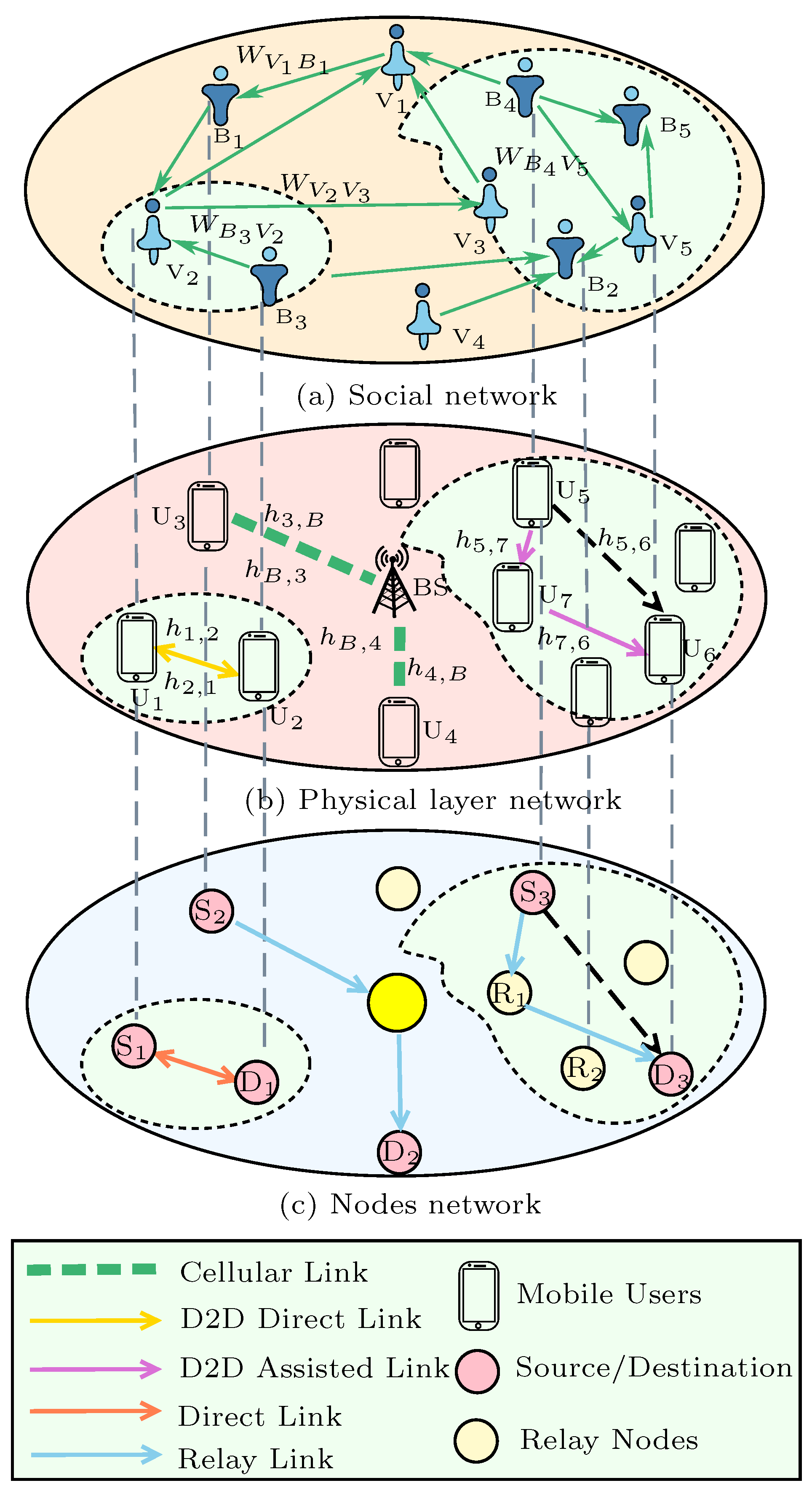
For readers’ quick reference, all the notations used in this paper are listed in Nomenclature.

2.1. System Model

Referring to Figure 1, the model can be divided into three symmetric layers consisting of a social network, a physical layer network, and a nodes network. The elements in different networks of the multi-layer network has symmetry property, i.e., the elements in each layer are in correspondence with those in the other two layers. For instance, the optimal user in the social network can correspond to the most suitable UE in the physical layer network and the optimal node in the third layer network. In this paper, the core concept of our research is utilizing the features of a social network to solve the key issue of a physical layer network in which a single-cell scenario with one BS and N users (UEs) is considered. The BS is located at the center of a cell and the UEs are randomly distributed with density λ u (users/m 2 ) following a homogeneous Poisson Point Process (PPP) [37], as shown in Figure 1b.
In this paper, we define three communication modes for the physical layer network. The UEs can adaptively select one communication mode according to the energy consumption.
  • Cellular Communication. Two UEs communicate with each other through the conventional cellular network, in which they transmit information through the BS. As shown in Figure 1b, U 3 communicates with U 4 using the cellular communication mode.
  • Direct D2D Communication. The source UE transmits information to the destination UE through the direct D2D link without the help of the BS or other UEs. In Figure 1b, U 1 and U 2 are exchanging messages utilizing the direct D2D communication mode.
  • Relay-assisted D2D Communication. Two UEs can send messages to each other directly with the assistance of a relay device selected from their neighboring UEs. Like the second mode, the transmission utilizing this mode can also be accomplished independently without the BS. For instance, U 5 is communicating with U 6 through this mode in Figure 1b.
In order to mitigate interference, all UEs in our architecture are under the control of the BS. Each UE is assumed to transmit information to the UEs in the same cell.
We consider that all channels adhere to the Rayleigh fading path-loss model. The path-loss exponent is denoted by μ , which is supposed to be the same for the whole network. Reflecting the fading severity of the channel between U i and U j , the channel coefficient h i j is used to represent the channel quality. Without loss of generality, we define the channel coefficient h i j between each two UEs as independent, identically distributed complex Gaussian random variables with h i j CN ( 0 , σ i j 2 ) . As shown in Figure 1b, we assume that h i j = h j i . Consequently, the received power P r e = a 0 · P t r a d μ · h i j , where P t r a denotes the transmit power, a 0 is a constant that depends on the transmitting and receiving antenna as well as the signal wavelength, and d is the distance between the transmitting UE and receiving UE. Considering the interference power P I and noise power P N , the signal-to-interference-plus-noise ratio (SINR) at the receiving UE is S I N R = P r e P I + P N , which can be rewritten as
S I N R = a 0 · h i j d μ · P t r a P I + P N .
When the required minimum SINR is set as S I N R 0 , we can achieve the minimum transmit power as
P t = S I N R 0 ( P I + P N ) d μ a 0 · h i j .
For simplicity of presentation, we apply a common model to evaluate the total energy consumption during one transmission. In particular, it can be formulated as
E = P t · t + E ˜ ,
where t is the transmission duration and E ˜ is the energy consumption for receiving and decoding the information at the destination. In Equation (3), P t · t can be explained as the energy consumption for information transmission at the source.
In the social network layer, each connection represents the relationship between two UEs, and the weight of the connection describes how close the relationship is. Obviously, the closer the relationship is, the higher the credibility will be. In the real world, for example, we can realize the closeness of any two people through their phone call logs or Short Messaging Service (SMS) logs. It is also easy to obtain the relationship among people according to online social network services. Considering the asymmetry of UEs in the social network, performance of UEs varies with location, so we can calculate the importance of each UE in the network using different metrics. Consequently, in our relay selection scheme, proximity prestige and spreading ability are formulated into the expression for selection criteria to improve the security of transmission in cooperative D2D communication.
As shown in Figure 1a, the edge between two UEs is a directed line segment. When node i can reach node j, the line segment will point from node i to node j, such as V 1 and B 1 in Figure 1a. Note that V 1 can reach B 1 but not vice versa. In directional networks, the in-degree of one node is the number of incoming links into this node and the number of outgoing edges is its out-degree. Compared with the out-degree, the in-degree can indicate the reliability of one service more exactly. For example, the incoming calls of “police call” and the outgoing calls of “fraudulent call” must be larger than that of other UEs. Therefore, we select the proximity prestige, which is closely related to the in-degree, as an important indicator. We assume that the social network consists of N nodes, and the proximity prestige [38] of node i is given as
P i = n i 2 ( N 1 ) j Ψ i d ˜ j i ,
where n i denotes the number of nodes that can directly or indirectly reach node i in the whole network; the set of the n i nodes is denoted by Ψ i which can be defined as the input domain of the node i; and d ˜ j i denotes the shortest path length from node j ( j Ψ i ) to node i. For example, as shown in Figure 1a, the proximity prestige of node V 1 is P V 1 = 5 2 ( 10 1 ) × ( 2 + 1 + 1 + 2 + 1 ) = 25 63 . Moreover, another feature of the social network is the spreading ability of an edge, which is calculated by
Q i j k = f i j k r = 1 N 1 f i j r ,
where f i j k denotes the number of common neighbors between nodes i and j k . In our scheme, the nodes directly connected to node i and pointed to by node i are defined as the neighbor of node i. For example, in Figure 1a, B 1 is a neighbor of V 1 , but V 1 is not included in the neighbors of B 1 . Obviously, in Equation (5), Q i j k = 0 , if f i j r = 0 . Even without common neighbors between node i and j k , the edge should be allowed to transmit information but with a low probability. With this concept, a parameter η > 0 [39] is defined and Equation (5) can be modified to
Q i j k = 1 η + f i j k 1 η ( N 1 ) + r = 1 N 1 f i j r .
As shown in Equation (6), the more common neighbors between two nodes, the stronger the spreading ability of the edge between the two nodes will be. Obviously, when the spreading ability of the edge is enhanced, the reliability between the two nodes will also increase.
The node network layer shown in Figure 1c can be regarded as a universal network model in which the nodes and edges are attached with different properties for diverse application scenarios. For instance, our proposed joint security and energy-efficient cooperative architecture can be regarded as an application of the universal network model in a 5G cellular network. In this architecture, the nodes and edges represent devices and channels, respectively. The weight of each edge denotes the “social network credibility” of the channel.

2.2. Assumptions

In order to make the system model further distinct, assumptions made in the analysis procedure are listed as follows.
  • We assume that all UEs can communicate with others, either through cellular communication or through D2D communication. When a UE is idle, it should switch to D2D mode automatically and be discovered by UEs utilizing relay-assisted D2D communication.
  • Orthogonal Frequency-Division Multiple Access (OFDMA) is considered for all UEs in this architecture. In the underlaying cellular network, the uplink (UL) spectrum resources are usually underutilized compared to the downlink (DL) [40]. Consequentially, D2D links in the proposed cooperative communication architecture can reuse the UL spectrum resources in the cellular network.
  • The cellular UL frequency spectrum provides a number of orthogonal channels with the same bandwidth. The BS allocates channels for UEs. At most, one D2D link shares one channel with a cellular link and one channel can only be reused by one D2D link at one time.
  • Each D2D UE works in full-duplex mode, which means that the UEs can transmit or receive information in the same time slot and frequency band.
  • Every UE can be selected as a relay device and it is able to discover and be discovered by other UEs. Only the idle UEs can be selected as relay devices and one D2D transmission can only be assisted by at most one relay. Moreover, the relay devices are assumed to utilize the decode-and-forward (DF) strategy to improve the reliability of a transmission.
  • We suppose that the BS is aware of all the required information, including channel coefficients, distances and devices’ battery statuses. When a UE requests one transmission, the states of all UEs in the cell will not change until the end of this communication.

3. Proposed Cooperative Architecture and Performance Analysis

In this section, first, we define several channel types and describe the proposed Channel Allocation Method (CAM). Next, our Joint Security and Energy-Efficient Cooperative Architecture (JSE-CA) is introduced in three steps. The last is performance analysis, which can mathematically evaluate the performance of the proposed JSE-CA.

3.1. Definitions

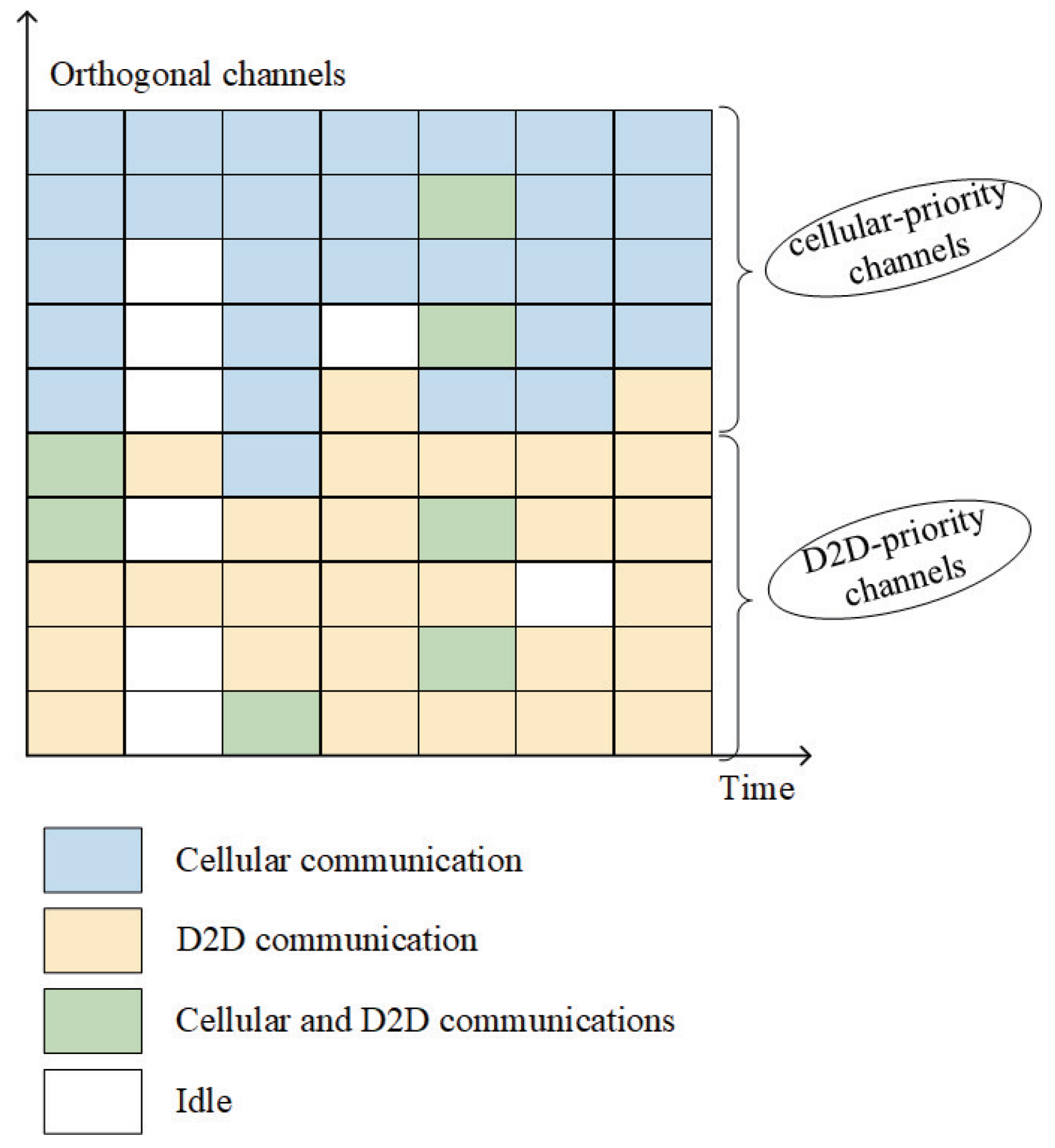
3.1.1. Channel Classification

As mentioned in Section 2.2, we consider an OFDMA-based cellular network in which the spectrum band provides M orthogonal channels and the time is equally divided into a large amount of OFDMA frames, each lasting a few milliseconds. To minimize the interference between D2D and cellular communications, we divide the orthogonal channels into two categories, which are defined as cellular-priority channels and D2D-priority channels. We consider that the cellular-priority channels are given the priority when a channel should be allocated to a cellular communication by the BS. Instead, the D2D communication has the priority of selecting D2D-priority channels. Furthermore, the cellular-priority channels are divided into four types: busy cellular-priority (BCP) channels, idle cellular-priority (ICP) channels, half-cellular-idle cellular-priority (HCICP) channels, and half-D2D-idle cellular-priority (HDICP) channels. Analogously, the D2D-priority channels can also be divided into busy D2D-priority (BDP) channels, idle D2D-priority (IDP) channels, half-cellular-idle D2D-priority (HCIDP) channels and half-D2D-idle D2D-priority (HDIDP) channels. BCP and BDP channels denote the channels that are being utilized by cellular and D2D communications simultaneously, indicated as “Cellular and D2D communications” channels in Figure 2. ICP and IDP channels can be explained as the channels not occupied by any communications, indicated as “Idle” channels in Figure 2. We define the channels used in D2D but not in cellular at some point as HCICP and HCIDP channels, which can be denoted by “D2D communication” channels in Figure 2. Moreover, the “Cellular communication” channels in Figure 2 can denote HDICP and HDIDP channels, which means that the channels are only utilized by cellular communication.
Let M D denote the number of D2D-priority channels and M C denote the number of cellular-priority channels. We assume that M D = M C = M 2 . For example in Figure 2, M D = M C = 5 . Let N D D and N D C denote the numbers of D2D-priority channels used by D2D UEs and cellular UEs, respectively, N C D and N C C denote the numbers of cellular-priority channels used by D2D UEs and cellular UEs, respectively. We define the channel utilization as the ratio of the number of busy channels to the total number of channels. It can be expressed by
ς = N D D + N D C + N C D + N C C M × 100 % ,
where ς [ 0 , 2 ] , N D D , N D C , N C D and N C C [ 0 , M 2 ] . For example, in Figure 2, M D = M C = 5 . In the first time-slot, N D D = 5 , N D C = 2 , N C D = 0 , and N C C = 5 , consequently, the channel utilization ( ς 1 ) can be obtained by Equation (7), i.e., ς 1 = N D D + N D C + N C D + N C C M × 100 % = 5 + 2 + 0 + 5 10 × 100 % = 120 % .

3.1.2. Channel Allocation Method

When the transmitter of cellular communication requests a transmission, the BS will detect the channels immediately. If there is at least one ICP channel, the BS will allocate one randomly for the transmitter; otherwise, if the number of HCICP channels is not zero, the transmitter can be allocated one randomly. Only when all M C cellular-priority channels are used will a D2D-priority channel be selected. When a D2D-priority channel is needed for the cellular communication, the IDP channels have priority over HCIDP channels. Analogously, suppose a D2D communication transmitter tries to communicate with others. If (i) at least one D2D-priority channel is idle or (ii) the number of HDIDP channels is not zero, the BS will not allocate a cellular-priority channel to the D2D transmitter. Only if all the M D D2D-priority channels are busy can the transmitter communicate through a cellular-priority channel.
In the actual transmission, if a D2D UE is allocated a channel which is also used by cellular communication, the D2D and cellular communication will interfere with each other. We define the probability that a cellular-priority or D2D-priority channel utilized by both D2D and cellular communication simultaneously as the Reuse Probability (RP). In our cooperative architecture, for different communication modes, the RP and interferences are different. Consequently, we define an equivalent interference power based on the communication mode. For example, P I D 2 D = p D 2 D R P · P I denotes the equivalent interference power of cellular communication on D2D communication, where p D 2 D R P is the RP when a channel is allocated to a D2D communication. According to the aforementioned channel allocation principle, when a D2D UE is allocated one D2D-priority channel, the RP is zero if N D D + N D C M 2 < 0 . Similarly, when a D2D is allocated one cellular-priority channel and N C D + N C C M 2 < 0 , the RP is also zero.
Define a b = a ! b ! ( a b ) ! . If a D2D communication needs to be allocated a channel, we calculate the RP, denoted by p D 2 D R P , as follows.
  • When M 2 > N D D ,
    p D 2 D R P = 0 , N D C + N D D < M 2 , N D D N D C + N D D M 2 M 2 N D C , o t h e r w i s e .
  • When M 2 = N D D ,
    p D 2 D R P = 0 , N C D + N C C < M 2 , N C D N C C + N C D M 2 M 2 N C C , o t h e r w i s e .
Moreover, if the relay-assisted D2D mode has been selected, the equivalent interference power of the first transmission phase can be calculated by P I D 2 D = p D 2 D R P · P I , Equations (8) and (9). Due to the full-duplex relaying mode, the second transmission phase cannot select the same channel with the first phase. Consequently, the number of N D D or N C D in the second transmission phase will increase. We define the equivalent interference power of the second transmission phase as P ^ I D 2 D = p ^ D 2 D R P · P I , where p ^ D 2 D R P denotes the RP in the second phase of relay-assisted D2D mode. Analyzing the RP within different situations gives the following result.
  • When M 2 N D D > 1 , a D2D-priority channel will be selected for the second phase. p ^ D 2 D R P can be calculated by
    p ^ D 2 D R P = 0 , N D D + 1 + N D C < M 2 , N D D + 1 N D D + 1 + N D C M 2 M 2 N D C , o t h e r w i s e .
  • When M 2 N D D = 1 , a cellular-priority channel will be selected and p ^ D 2 D R P is obtained by
    p ^ D 2 D R P = 0 , N C D + N C C < M 2 , N C D N C C + N C D M 2 M 2 N C C , o t h e r w i s e .
  • When M 2 N D D < 1 , p ^ D 2 D R P can be written as
    p ^ D 2 D R P = 0 , N C D + 1 + N C C < M 2 , N C D + 1 N C D + 1 + N C C M 2 M 2 N C C , o t h e r w i s e .
Analogously, the equivalent interference power of D2D communication on cellular communication is denoted by P I c e l l u l a r = p c e l l u l a r R P · P I , where p c e l l u l a r R P is the RP of allocating one channel to a cellular UE and it can be expressed as follows.
  • When M 2 > N C C ,
    p c e l l u l a r R P = 0 , N C D + N C C < M 2 , N C C N C C + N C D M 2 M 2 N C D , o t h e r w i s e .
  • When M 2 = N C C ,
    p c e l l u l a r R P = 0 , N D C + N D D < M 2 , N D C N D C + N D D M 2 M 2 N D D , o t h e r w i s e .

3.2. Joint Security and Energy-Efficient Cooperative Architecture

For the sake of energy conservation and security, we propose a symmetric cooperative architecture in which an adaptive D2D communication algorithm is designed. The algorithm can be divided into the following three phases.

3.2.1. Communication Request

We assume that all UEs are under the control of the BS, which is aware of the status about each UE. As a consequence, when a UE wants to transmit information to others, it will send the communication request, including the identity information of receiver to the BS. It then waits for the BS to allocate an appropriate channel for the transmission.

3.2.2. Mode Selection

Three optional communication modes are considered for the second phase, which is the core of the architecture: cellular communication, direct D2D communication, and relay-assisted D2D communication. According to the location information and channel quality of the two UEs, the BS will select the best one among the three modes for the current transmission, with the aim of reducing energy consumption.
To describe and compare the energy consumption of the three communication modes more clearly, we assume that the transmitting duration ( t 0 ), noise power ( P N ), signal transmitting rate ( v 0 ), as well as the energy consumption for receiving and decoding information at the destination UE ( E R D E ) are identical for all modes. Consequently, we formalize the energy consumption of the three modes based on Equation (3) as follows.
E c e l l u l a r = P t c · t S B + E R D E = S I N R 0 ( P I c e l l u l a r + P N ) a 0 · h S B · d S B μ · t 0 + E R D E = A · d S B μ ( p c e l l u l a r R P P I + P N ) h S B + E R D E ,
where A = S I N R 0 · t 0 a 0 is a constant. Likewise, we express E D 2 D as
E D 2 D = P t d · t S D + E R D E = A · d S D μ ( p D 2 D R P P I + P N ) h S D + E R D E ,
and calculate E r e l a y D 2 D by
E r e l a y D 2 D i = P t r d · t S R i + E R D E + P t R i · t R i D + E R D E = A · ( d S R i μ ( p D 2 D R P P I + P N ) h S R i + d R i D μ ( p ^ D 2 D R P P I + P N ) h R i D ) + 2 E R D E ,
where E D 2 D denotes the energy consumption of D2D communication and E r e l a y D 2 D i denotes the energy consumption of relay-assisted D2D communication with relay device i. We set the coordinates of (i) base station BS to be ( 0 , 0 ) , (ii) Source S to be l S = ( x S , y S ) , (iii) Destination D to be l D = ( x D , y D ) and (iv) relay R i to be l R i = ( x R i , y R i ) . As a consequence, the geographical distance in Equations (15)–(17) can be further written as d S B = [ ( x S ) 2 + ( y S ) 2 ] 1 2 , d S D = [ ( x S x D ) 2 + ( y S y D ) 2 ] 1 2 , d S R i = [ ( x S x R i ) 2 + ( y S y R i ) 2 ] 1 2 and d R i D = [ ( x R i x D ) 2 + ( y R i y D ) 2 ] 1 2 .
For the sake of energy conservation and the UE experience, we select an appropriate communication mode for the transmitting UE by comparing the energy consumptions. The mode selection of the adaptive cooperative communication algorithm can be formulated as
M o d e = arg min ϱ M E ϱ ,
where M = {cellular, D2D, relay-D2D}. To improve the energy efficiency of UEs, the energy consumption excludes the energy consumed at the BS.
Supposing E c e l l u l a r E D 2 D , we have E c e l l u l a r E D 2 D 0 , which can be derived as
A · ( d S B μ ( p c e l l u l a r R P P I + P N ) h S B d S D μ ( p D 2 D R P P I + P N ) h S D ) 0 .
Using the fact that A > 0 , we obtain d S B μ · P c e l l u l a r I N h S B d S D μ · P D 2 D I N h S D 0 , where P c e l l u l a r I N = p c e l l u l a r R P P I + P N , P D 2 D I N = p D 2 D R P P I + P N .
Based on the above consideration, the cellular mode will be selected and the BS will detect the M C cellular-priority channels. If there are idle cellular-priority channels, the BS will select one randomly; otherwise, if there is at least one HCICP channel, one of these channels will be selected. When all cellular-priority channels are busy, the BS can detect the M D D2D-priority channels and select one randomly from the IDP channels or HCIDP channels. In a similar way, an appropriate channel can be selected for direct D2D communication.
Moreover, if there exists i V 1 , V 1 ={i, i { 1 , 2 , , N } and i S , D }, such that E r e l a y D 2 D i < E D 2 D , then
A · ( d S R i μ · P D 2 D I N h S R i + d R i D μ · P ^ D 2 D I N h R i D d S D μ · P D 2 D I N h S D ) + E R D E < 0 ,
P D 2 D I N ( d S D μ h S D d S R i μ h S R i ) d R i D μ · P ^ D 2 D I N h R i D > E R D E A τ ,
where P ^ D 2 D I N = p ^ D 2 D R P P I + P N . Under this circumstance, the relay-assisted D2D communication mode will be selected. We can evaluate a region in which the relay-assisted D2D communication mode is the most energy efficient, with a given value of τ . When the relay-assisted D2D communication mode is selected, we have to select an appropriate relay device in addition to a channel for the D2D communication pair.
Nowadays, more and more people pay attention to data security rather than the improved transmission performance. Consequently, combining the features of social networks and physical layer networks, we propose a novel relay selection scheme consisting of two steps to select a secure and high-quality relay device for relay-assisted D2D communication. First, to reduce the complexity of the selection, we define a QoS region based on energy consumption, devices’ battery statuses and the UEs’ states. We assume that there are N ˜ relays in the QoS region where E r e l a y D 2 D i < E D 2 D , ∀ i V 2 , V 2 = { 1 , 2 , , N ˜ } . In addition, the remaining battery of all N ˜ candidate relay devices in this region is equal to or greater than ρ which is the threshold for “Low Battery”. To improve the efficiency, the QoS region excludes busy UEs which are assisting transmission as a relay at that moment, as well as the UEs whose remaining battery is less than ρ . However, if there is no device in this QoS region, the minimum threshold ρ will be reduced by κ % until the QoS region is non-empty.
In the second step, we propose a novel criterion for relay selection. In real social networks, the credibility of every person is different due to the asymmetry of the network. Furthermore, the nature of a person and the relationship between himself and others will affect the credibility of this person. As illustrated in [39], in-degree is considered as an important criterion representing the credibility of one node, and the number of common neighbors between two connected nodes determines the reliability of the corresponding edge. To indicate the credibility of a selected relay device, we combine the proximity prestige of the node and the spreading ability of the connecting edge. For social networks, we define the credibility of one node relative to others as “Combined Proximity Prestige and Spreading Ability (CPSA)”. The CPSA of node i relative to node j is expressed by W i j . As shown in Figure 1a, when UE B 1 requires using the relay device V 1 , W V 1 B 1 denotes the reliability of UE V 1 combining the proximity prestige of V 1 and the closeness between B 1 and V 1 . By normalizing P i and Q i j k , the CPSA of node i relative to node j k can be defined as
W i j k = 1 2 ( P i max 1 j N ˜ P j + Q i j k max 1 j N ˜ Q i j ) 1 .
Similarly, we calculate the equivalent energy consumption through the current transmission with relay device i as
E ˜ r e l a y D 2 D i = min 1 j N ˜ E r e l a y D 2 D j E r e l a y D 2 D i 1 .
Integrating social network and physical layer performance, the proposed criterion in our adaptive cooperative communication algorithm is defined as “Combined Energy Consumption and Security (CECS)”, which can be calculated by
W i = α E ˜ r e l a y D 2 D i + β W i S = α min 1 j N ˜ ( d S R j μ · P D 2 D I N h S R j + d R j D μ · P ^ D 2 D I N h R j D ) + 2 τ ( d S R i μ · P D 2 D I N h S R i + d R i D μ · P ^ D 2 D I N h R i D ) + 2 τ + β 2 ( P i max 1 j N ˜ P j + Q i S max 1 j N ˜ Q i j ) α + β = 1 ,
where α and β are adjustable non-negative coefficients which can be utilized to control the weights of different indexes. According to the actual situation, different relay UEs can be selected by changing the value of α and β . In this step, the UE i in the QoS region with the largest W i will be selected to cooperate with Source as a relay, i.e.,
i = arg max i V 2 W i .

3.2.3. Data Transmission

The last phase is data transmission. Utilizing the most energy-efficient mode, the transmitter will send information to receiver through the channel allocated by BS. Receiving the message successfully, the receiver will disconnect this transmission.
The above analysis process is shown in Algorithm 1 named “The adaptive D2D communication algorithm”.
Algorithm 1 The adaptive D2D communication algorithm
Input:N, τ , μ , α , β , η .
1: Construct a random network, determine Source S and Destination D.
Set V 1 ={i, i { 1 , 2 , , N } and i S , D }, calculate E c e l l u l a r , E D 2 D , E r e l a y D 2 D i and M o d e
2: if  M o d e !=relay-D2D then return M o d e
3: else
4: for i V 1  do
5: Define a QoS region, obtain N ˜ candidate relay UEs
6: end for
7: Set V 2 = { 1 , 2 , , N ˜ }
8: for i V 2  do
9: Calculate W i using Equation (24)
10: end for
11: Obtain i using Equation (25) return M o d e and i
12: end if
Output: The selected communication mode and relevant parameter values.

3.3. Performance Analysis

In this section, we evaluate the performance of the proposed channel allocation method based on reuse probability, the relay selection scheme based on social network security rate, as well as the system based on energy consumption, outage probability, and throughput.

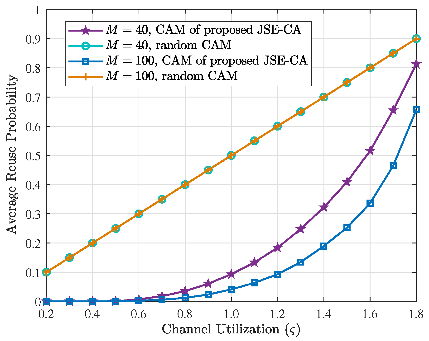
3.3.1. Reuse Probability

The Reuse Probability of the three transmission modes can be calculated by Equations (8)–(14). To compare the effectiveness of the proposed channel-allocation scheme, we also analyze a random allocation method, in which one of the available channels will be randomly allocated for the transmitting UE. For example, when a D2D communication requires a channel, one of the IDP channels or HDIDP channels will be randomly allocated to this communication. Only if the numbers of the two channel types are 0 will a cellular-priority channel be allocated using the same criterion as D2D-priority channels allocation. The RP of random allocation method can be calculated as follows. When M 2 > N D D ,
p ˜ D 2 D R P = M 2 1 N D C 1 M 2 N D C = ( M 2 1 ) ! ( N D C 1 ) ! · ( M 2 N D C ) ! ( M 2 ) ! ( N D C ) ! · ( M 2 N D C ) ! = N D C M 2 .
Likewise, p ˜ D 2 D R P = M 2 1 N C C 1 M 2 N C C = N C C M 2 , when M 2 = N D D . Consequently, when a D2D UE is allocated a channel randomly, the RP can be transformed as
p ˜ D 2 D R P = 2 N D C M , M 2 > N D D , 2 N C C M , o t h e r w i s e .
Analogously, when a cellular UE is allocated one random channel, the RP can be written as
p ˜ c e l l u l a r R P = 2 N C D M , M 2 > N C C , 2 N D D M , o t h e r w i s e .

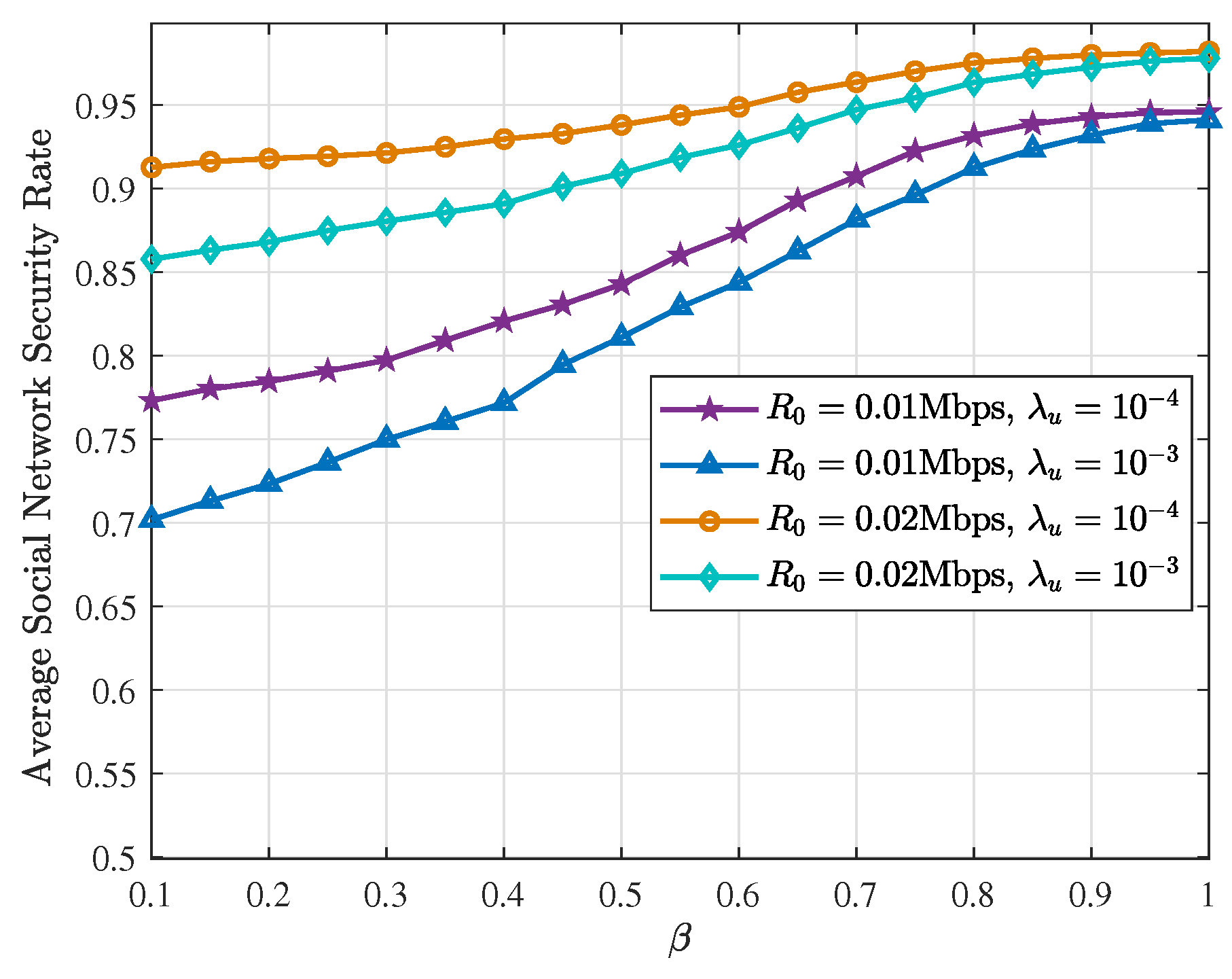
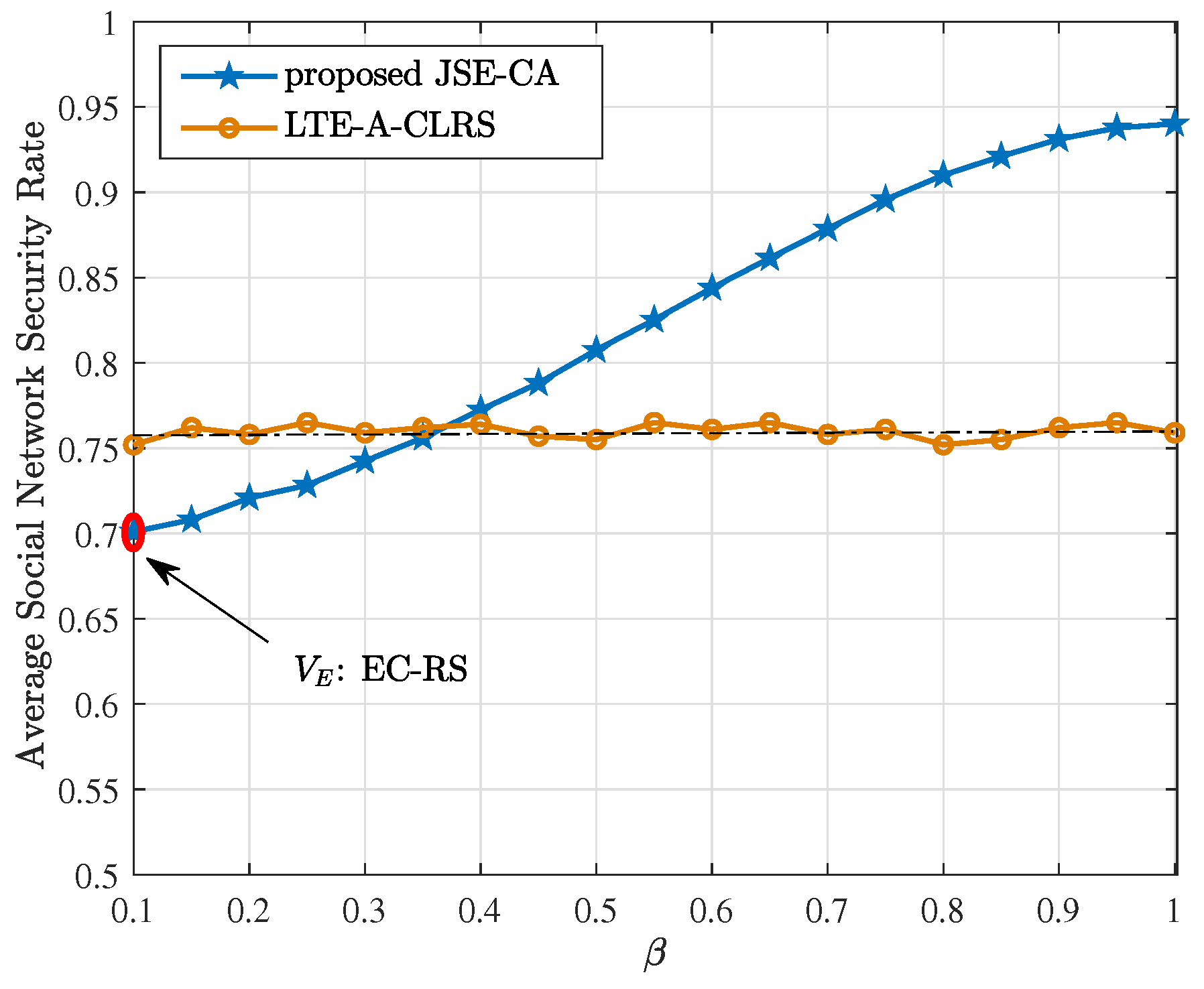
3.3.2. Social Network Security Rate

In the proposed cooperative architecture, we assume that if node i successfully decodes the information transmitted by node j, it will spread this information maliciously with a probability p M a , j i , which is assumed to be negatively related to the CPSA of node i relative to node j. Furthermore, we define p M a , j i = 1 W i j and hence 0 p M a , j i 1 . Consequently, the information transmitted by node j is not necessarily secure. We define the probability of a secure transmission as “Social Network Security Rate” (SNSR) and denote it by p R S A i j . If node i has been selected as the relay device of Source S, the SNSR of the current transmission can be calculated by
p R S A i S = 1 p M a , S i · p S u c c i S = 1 ( 1 W i S ) · p S u c c i S = 1 [ 1 1 2 ( P i max 1 j N ˜ P j + Q i S max 1 j N ˜ Q i j ) ] ( 1 p o u t i S ) ,
where p M a , S i S and p S u c c i S denote the malicious spreading probability and successful decoding probability of relay device i, respectively; p o u t i S is the outage probability of the first phase of relay-assisted D2D communication with relay device i. We suppose that the minimum transmission rate is denoted as R 0 and the variance of channel coefficient σ i j 2 = 1 . According to the Shannon’s theorem, we can obtain the outage probability p o u t i S with relay i as follows:
p o u t i S = P [ 1 2 log 2 ( 1 + S I N R S R i ) < R 0 ] = P [ 1 2 log 2 ( 1 + a 0 · P t r d · h S R i d S R i μ · P D 2 D I N ) < R 0 ] = P [ h S R i < 2 2 R 0 1 a 0 P t r d · d S R i μ · P D 2 D I N ] = 0 2 2 R 0 1 a 0 P t r d · d S R i μ · P D 2 D I N exp ( h S R i ) d h S R i = 1 exp ( 2 2 R 0 1 a 0 P t r d · d S R i μ · P D 2 D I N ) ,
where S I N R S R i denotes the SINR at relay node i. Substituting Equations (30)–(29), we have
p R S A i S = 1 [ 1 1 2 ( P i max 1 j N ˜ P j + Q i S max 1 j N ˜ Q i j ) ] · exp ( 2 2 R 0 1 a 0 P t r d · d S R i μ · P D 2 D I N ) .

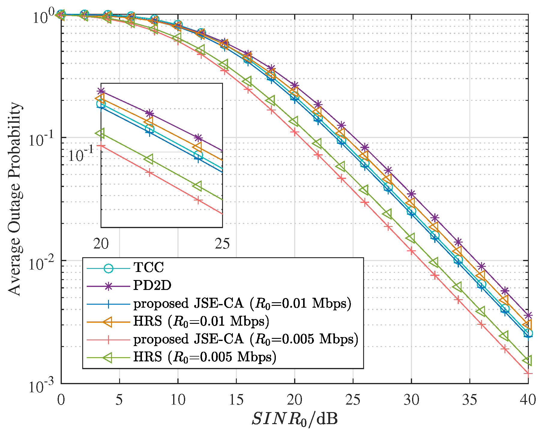
3.3.3. Outage Probability
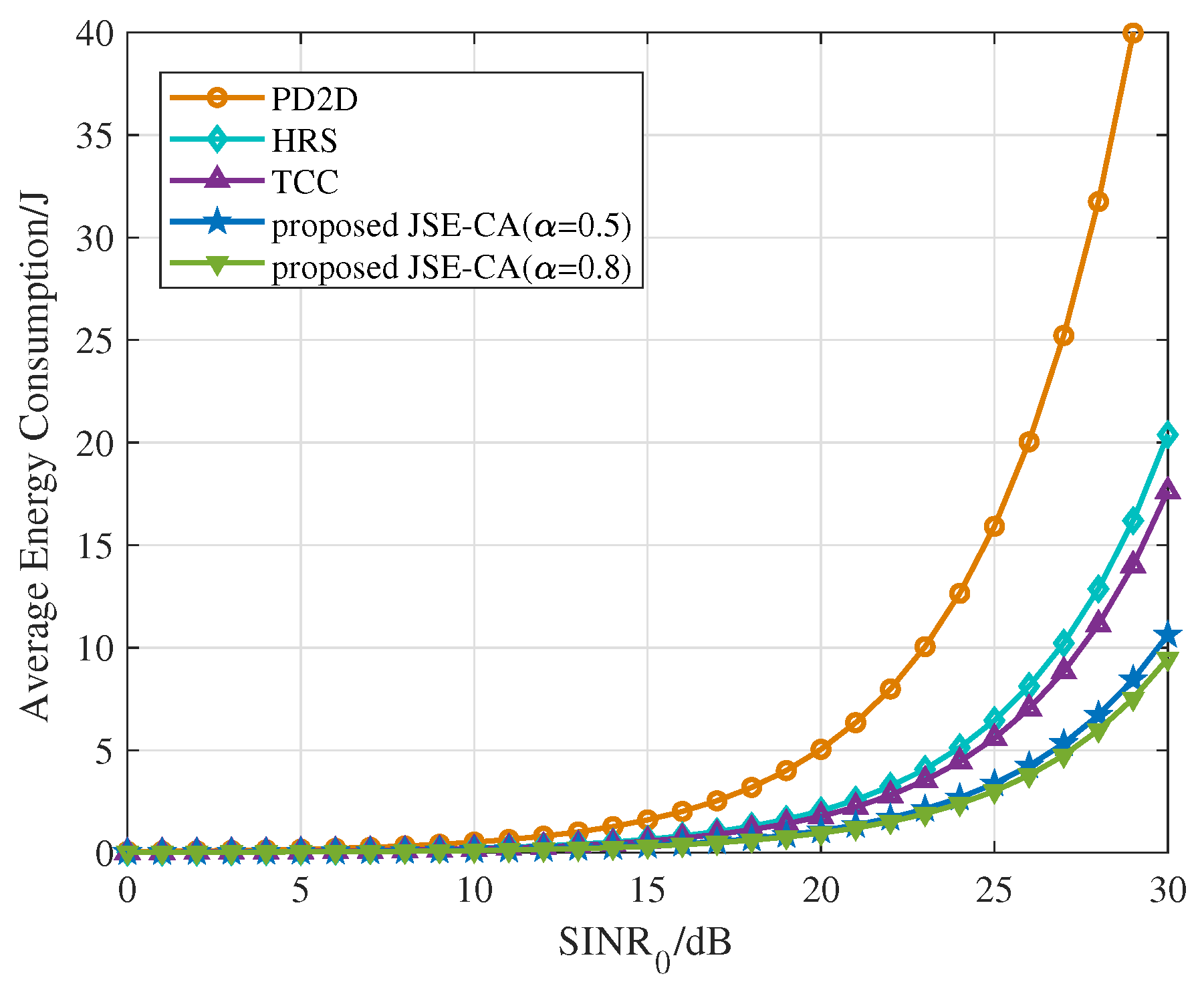
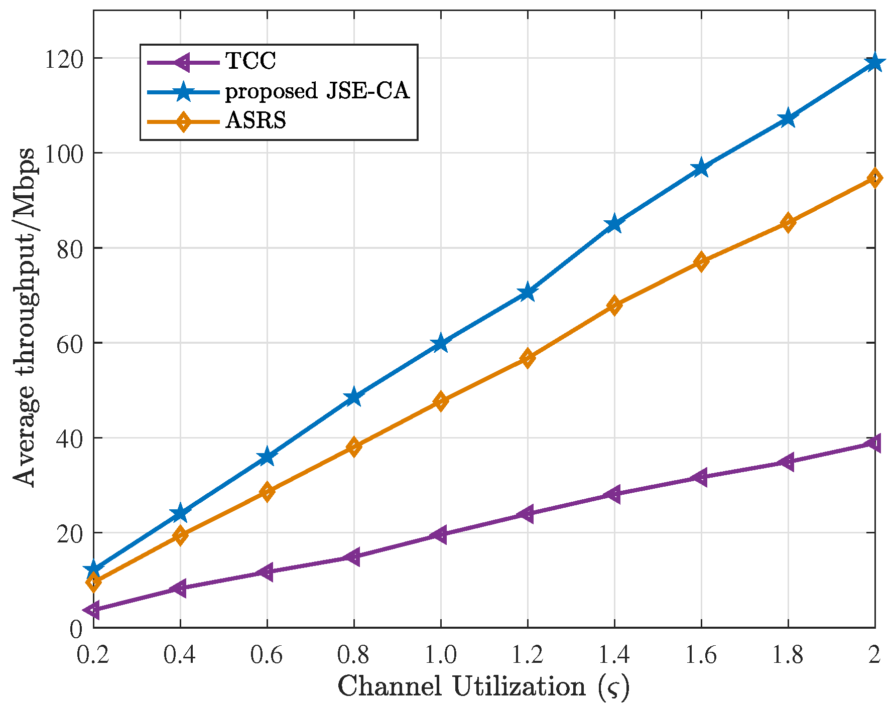
In the proposed cooperative architecture, if cellular communication mode has been employed, we consider that the BS can ensure the reliability of the second phase transmission. The outage probability depends entirely upon the first phase. Consequently, referring to Equation (30), we express the outage probability of cellular communication as
p c e l l u l a r o u t = P [ 1 2 log 2 ( 1 + a 0 · P t c · h S B d S B μ · P c e l l u l a r I N ) < R 0 ] = 1 exp ( 2 2 R 0 1 a 0 P t c · d S B μ · P c e l l u l a r I N ) .
Likewise, the outage probability of direct D2D communication can be calculated by
p D 2 D o u t = P [ 1 2 log 2 ( 1 + a 0 · P t d · h S D d S D μ · P D 2 D I N ) < R 0 ] = 1 exp ( 2 2 R 0 1 a 0 P t d · d S D μ · P D 2 D I N ) ,
where P D 2 D I N and P c e l l u l a r I N can be obtained from Equations (8)–(14), respectively.
If the relay-assisted D2D mode has been selected to transmit information, the outage probability will be affected by the transmission reliability of each phase. Hence, for relay-assisted D2D communication, we have p r e l a y D 2 D o u t = 1 ( 1 p S R i o u t ) ( 1 p R i D o u t ) , where
p S R i o u t = 1 exp ( 2 2 R 0 1 a 0 P t r d · d S R i μ · P D 2 D I N ) , p R i D o u t = 1 exp ( 2 2 R 0 1 a 0 P t R i · d R i D μ · P ^ D 2 D I N ) .

3.3.4. Throughput

The throughput of one cell at some point, denoted by T, can be defined as the throughput sum of all transmission pairs accessing the network. If there are ε transmission pairs accessing the network at τ (time slot), we denote the ith transmission pair as ξ i , i {1, 2, ⋯, ε }. The throughput of this cell at time slot τ denoted by T τ can be calculated by
T τ = T ξ 1 τ + T ξ 2 τ + + T ξ ε τ .
According to [41], in a full-duplex relaying system using decode-and-forward protocol, the throughput of the transmission pair ξ S D assisted by relay UE R i at time slot τ can be expressed as
T R i D 2 D τ = 1 2 min ( log 2 ( 1 + S I N R S R i ) , log 2 ( 1 + S I N R R i D ) ) .
For cellular communication mode, we consider that the BS can help to improve the instantaneous SINR at Destination D. The throughput of this mode all depends on the first phase and equals
T c e l l u l a r τ = 1 2 log 2 ( 1 + S I N R S B ) .
Clearly, the throughput of the direct D2D communication at time slot τ can be calculated by
T D 2 D τ = 1 2 log 2 ( 1 + S I N R S D ) .
The SINRs in Equations (36)–(38) are given by S I N R S R i = a 0 · P t r d · h S R i d S R i μ · P D 2 D I N , S I N R R i D = a 0 · P t R i · h R i D d R i D μ · P ^ D 2 D I N , S I N R S B = a 0 · P t c · h S B d S B μ · P c e l l u l a r I N and S I N R S D = a 0 · P t d · h S D d S D μ · P D 2 D I N .

4. Numerical Results

The performances of the proposed joint security and energy-efficient cooperative architecture (JSE-CA) are evaluated in this section via independent Monte Carlo simulations. The performance metrics include the average RP, SNSR, energy consumption, outage probability, and throughput. To validate the advantages of the proposed architecture, we also give some comparisons with traditional communication architecture employing various relay selection schemes, including the cross-layer relay selection scheme for a long-term evolution-advanced (LTE-A) system [42], the hybrid relay selection (HRS) combining conventional best relay selection (BRS) and max–max relay selection (MMRS) [43], as well as the autonomous sociality relay selection (ASRS) [44]. We using MATLAB R2020b to simulate the proposed cooperative architecture with a novel relay selection scheme. The simulations are performed under a common underlaying cellular network, where all UEs are uniformly and randomly distributed within a single square cell with each side of length d ˙ = 10 3 m. Other simulation parameters are as follows: a 0 = 1 m 2 , t 0 = 1 ms, P I = P N = 5 × 10 2 mW, μ = 2 , η = 10 , ρ = 20 % , κ = 2 , E R D E = 10 2 J.
We first investigate the performance of our proposed Channel Allocation Method (CAM) for different channel utilization. The average reuse probabilities of the proposed CAM in JSE-CA and random CAM for M = 40 and M = 100 are shown in Figure 3. As can be observed, the average RP is increasing in both methods as the channel utilization increases. Different numbers of orthogonal channels M result in different average RP when the CAM of JSE-CA is employed, but the average RP is constant when the random CAM is selected. This is because the RP of the random CAM is only related to the percentage of existing idle channels. In JSE-CA method, the idle channels will be allocated firstly, only if the channels are all busy can a half-D2D-idle channel or a half-cellular-idle channel be selected. Consequently, the average RP of JSE-CA is lower than that of the random CAM, as obviously observed in Figure 3. Furthermore, interference will increase as RP increases. The proposed CAM therefore outperforms the random CAM in terms of avoiding interference between D2D and cellular communication.
Figure 4 depicts the average social network security rate (SNSR) with different minimum transmission rate R 0 and user density λ u . The transmit power of each node is set to P t c = P t d = P t r d = P t R i = 10 mW. Clearly, the average SNSR is increasing in all cases as β increases, but the rate of increase decreases as β approaches one. The incremental user density can make the number of candidate relays satisfying the requirements increase, and thus can improve the successful decoding probability. Therefore, it can be observed that when we vary λ u , the average SNSR decreases for increasing UE density. However, decreasing R 0 will result in average SNSR decreasing. This is because decreasing the minimum transmission rate can also make the number of nodes in the Qos region increase and improve the successful decoding probability, which is negatively correlated with the SNSR.
In Figure 5, we provide the average SNSR performance of the LTE-A system with a cross-layer relay selection scheme (LTE-A-CLRS) [42], where end-to-end data rate, battery status of relay-capable UE and end-to-end transmission delay are considered. We also plot the average SNSR of our proposed JSE-CA. The results show that the average SNSR of our scheme outperforms that of LTE-A-CLRS when β > 0.37 and the difference between these two curves is increasing gradually as β increases. The reason is that focusing on energy consumption too much (i.e. increasing β ) will result in poor (lower) security. Inversely, increasing the weight of the social network in the relay selection criterion can obviously improve the security. Moreover, the point ( V E ) marked in Figure 5 indicates the average SNSR of the relay selection scheme (EC-RS) in which the selection criterion is mostly considering energy consumption ( β = 0.1 ). Obviously, our scheme is more efficient in terms of improving the security of transmission compared to EC-RS, especially as β approaches one.
Besides security, energy consumption evaluated by Equations (15)–(17) is another important indicator in the communication architecture. To illustrate the energy-efficiency performance of our scheme, we compare the average energy consumption (EC) of our proposed JSE-CA, the traditional cellular communication (TCC) and pure D2D communication (PD2D), as well as the scheme in [43]. Figure 6 shows the average EC of the communications utilizing the three modes (JSE-CA with different α , TCC and PD2D) and that of HRS in [43] as the SINR requirement at the receiving device ( S I N R 0 ) increases. From the figure, we can clearly observe that the proposed JSE-CA always achieves the best energy-efficiency performance among the four systems when α = 0.5 or α = 0.8 . The reason is that we take the energy consumption into selection criteria when a transmission mode needs to be determined or a relay user needs to be selected. Furthermore, the average EC decreases as α increases under different S I N R 0 . This is because increasing the weight of energy consumption ( α ) in the selection criterion can improve energy-efficiency performance effectively. Based on the results in Figure 5 and Figure 6, we select α = β = 0.5 in subsequent analysis.
Figure 7 demonstrates the transmission reliability, which is characterized by the outage probability of the proposed JSE-CA. We plot the simulated outage probability (OP) of the four communication systems (TCC, PD2D, JSE-CA, and HRS in [43]) as the SINR requirement of the receiving device increases. In our architecture, we define a QoS region containing a portion of better candidate relays for the relay selection scheme, which explains that the proposed JSE-CA can achieve the minimum outage probability compared with other schemes when R 0 = 0.01 Mbps, and the improvement slightly increases as the S I N R 0 increases. Moreover, the minimum transmission rate affects the average OP. When R 0 is lowered ( R 0 = 0.005 Mbps compared with R 0 = 0.01 Mbps, the average OP is reduced by 50 % under S I N R 0 = 40 dB), it becomes easier to achieve the minimum transmission rate. Consequently, the average OP decreases with R 0 decreasing.
Figure 8 shows the instantaneous throughput of the system at some point as channel utilization ( ς ) increases. As expected, the system utilizing our proposed JSE-CA achieves the best throughput performance among the three systems, since in our system, the number of UEs accessing the network simultaneously is the largest if there are enough channels to be selected. Note that with increased channel utilization, the throughput of the system increases gradually and the gaps extend among the curves. When ς approaches 2, compared with ASRS in [44], the throughput performance of the system utilizing our proposed JSE-CA increases by about 26 % . Thus demonstrating that our proposed JSE-CA can effectively improve the throughput performance of the system.

5. Conclusions

In this paper, we proposed a symmetric cooperative communication architecture, in which the UEs can adaptively select one communication mode aiming at energy conservation among cellular communication, direct D2D communication, and relay-assisted D2D communication. Furthermore, according to the data transmission requirements of UEs, which focus on security, high efficiency, and energy conservation, we present a novel relay selection scheme for the relay-assisted D2D communication. In this scheme, we first proposed a QoS region considering energy consumption, devices’ battery statuses and states to reduce the selection complexity. Then, we formulated selection criteria combining the social network characteristics and performance indexes of the physical layer network, such as distance, wireless channel quality between two devices, and energy consumption. The proposed joint security and energy-efficiency cooperative architecture with a novel social network-based relay selection outperforms the traditional cellular and D2D communications in terms of energy consumption, security, outage probability, and throughput. Taking S I N R 0 = 25 dB, α = β = 0.5 as an example, the energy consumption of the system utilizing our proposed JSE-CA decreased by about 76 % compared with PD2D and about 25 % compared with TCC. In addition, the average outage probability decreased by about 30 % and 6.7 % , respectively.

Author Contributions

Conceptualization, L.G. and Y.Z.; methodology, L.G. and F.C.M.L.; software, L.G.; validation, H.Y. and Y.Z.; formal analysis, L.G.; investigation, L.G.; resources, Z.Z.; data curation, L.G.; writing—original draft preparation, L.G.; writing—review and editing, F.C.M.L. and Y.Z.; visualization, L.G.; supervision, H.Y.; project administration, Z.Z.; funding acquisition, Z.Z. All authors have read and agreed to the published version of the manuscript.

Funding

This research was funded by the National Natural Science Foundation of China (Grant Nos. 61977014, 61603082, 61902056, 61902057).

Institutional Review Board Statement

Not applicable.

Informed Consent Statement

Not applicable.

Data Availability Statement

Not applicable.

Conflicts of Interest

The authors declare no conflict of interest.

Nomenclature

NNumber of users in a single cell
λ u User density
μ Path-loss exponent
h i j Channel coefficient of the channel between i and j
σ i j Constant
P r e Received power
P t r a Transmit power
a 0 Constant
dDistance between transmitting UE and receiving UE
P I Interference power
P N Noise power
S I N R The SINR at receiving UE
S I N R 0 Required minimum SINR
P t Minimum transmit power
EEnergy consumption
tTransmission duration
E ˜ Energy consumption at the receiving UE
P i Proximity prestige of node i
Ψ i Input domain of node i
n i Number of nodes in Ψ i
d ˜ j i The shortest path length from node j to i
Q i j k Spreading ability of the edge between i and j k
f i j k Number of common neighbors between i and j k
MNumber of orthogonal channels
M D Number of D2D-priority channels
M C Number of cellular-priority channels
N D D , N D C Number of D2D-priority channels used by D2D and cellular UEs
N C D , N C C Number of cellular-priority channels used by D2D and cellular UEs
ς Channel utilization
P I D 2 D Equivalent interference power of cellular on D2D communication
p D 2 D R P RP of allocating a channel to D2D UE
P I c e l l u l a r Equivalent interference power of D2D on cellular communication
p c e l l u l a r R P RP of allocating a channel to cellular UE
p ^ I D 2 D Equivalent interference power of cellular on D2D communication in the second phase
p ^ D 2 D R P RP of allocating a channel to D2D UE in the second phase
η Constant
E c e l l u l a r Energy consumption of cellular communication
E D 2 D Energy consumption of direct D2D communication
E r e l a y D 2 D i Energy consumption of relay-assisted D2D with i
P t c Transmit power of Source S in cellular communication
P t d Transmit power of Source S in direct D2D
P t r d Transmit power of Source S in relay-assisted D2D
P t R i Transmit power of relay user i
h S B Channel coefficient between Source S and BS
h S D Channel coefficient between Source S and Destination D
h S R i Channel coefficient between Source S and relay user i
h R i D Channel coefficient between relay i and Destination D
t S B Transmitting duration in Source S to BS communication
t S D Transmitting duration in Source S to Destination D communication
t S R i Transmitting duration in Source S to relay user i communication
t R i D Transmitting duration in relay user i to Destination D communication
d S B Geographical distance between Source S and BS
d S D Geographical distance between Source S and Destination D
d S R i Geographical distance between Source S and relay user i
d R i D Geographical distance between relay i and Destination D
t 0 Constant
E R D E Constant
A Constant
( x S , y S ) Location of Source S
( x D , y D ) Location of Destination D
( x R i , y R i ) Location of the relay device i
τ Constant
N ˜ Number of relay nodes in QoS region
ρ The minimum threshold of “Low Battery”
κ Constant
W i j k CPSA of node i relative to j k
W i S CPSA of node i relative to Source S
W i CECS of node i
α Weight of energy consumption
β Weight of CPSA
i The selected relay node
E ˜ r e l a y D 2 D i Equivalent energy consumption of D2D-assisted communication with relay device i
p ˜ D 2 D R P RP of randomly allocating a channel to D2D UE
p ˜ c e l l u l a r R P RP of randomly allocating a channel to cellular UE
p M a , S i Malicious spreading probability of i relative to Source S
p S u c c i S Successful decoding probability of i relative to Source S
p R S A i S Secure transmission probability of i relative to Source S
p o u t i S Outage probability of i relative to Source S
p S R i o u t Outage probability of the first phase for relay-assisted D2D communication
p R i D o u t Outage probability of the second phase for relay-assisted D2D communication
R 0 Minimum transmitting rate
p c e l l u l a r o u t Outage probability of cellular communication
p D 2 D o u t Outage probability of direct D2D communication
p r e l a y D 2 D o u t Outage probability of relay-assisted D2D communication
ξ i The ith transmission pair
T τ Throughput of one cell at τ
T R i D 2 D τ Throughput of relay-assisted D2D with R i at τ
T c e l l u l a r τ Throughput of cellular communication at τ
T D 2 D τ Throughput of direct D2D communication at τ

References

  1. Cisco Visual Networking Index: Global Mobile Data Traffic Forecast Update, 2016–2021 White Paper. Available online: https://www.reinvention.be/webhdfs/v1/docs/complete-white-paper-c11-481360.pdf (accessed on 6 June 2017).
  2. Freeman, H.; Dutta, A. 5G perspective. IEEE Commun. Mag. 2016, 54, 4–5. [Google Scholar]
  3. Gozalvez, J. 5G worldwide developments. IEEE Veh. Technol. Mag. 2017, 12, 4–11. [Google Scholar]
  4. Zhang, S.; Zhu, D.; Wang, Y. A sruvey on space-aerial-terrestrial integrated 5G network. Comput. Netw. 2020, 174, 1–18. [Google Scholar] [CrossRef]
  5. Zhang, C.J.; Ma, J.; Li, G.Y.; Kishiyama, Y.; Parkvall, S.; Liu, G.; Kim, Y.H. Key technology for 5G new radio. IEEE Commun. Mag. 2018, 56, 10–11. [Google Scholar] [CrossRef]
  6. Bao, W.; Liang, B. Structured spectrum allocation and user association in heterogeneous cellular networks. In Proceedings of the IEEE INFOCOM, Turin, Italy, 14–19 April 2013. [Google Scholar]
  7. Zhou, X.; Feng, S.; Ding, Y. Optimal spectrum allocation in the dynamic heterogeneous cellular network. IEICE Trans. Commun. 2016, 99, 240–248. [Google Scholar] [CrossRef]
  8. Cao, H.; Hu, Y.; Yang, L. Towards intelligent virtual resource allocation in UAVs-assisted 5G networks. Comput. Netw. 2021, 185, 1–11. [Google Scholar] [CrossRef]
  9. Asadi, A.; Wang, Q.; Mancuso, V. A Survey on device-to-device communication in cellular networks. IEEE Commun. Surv. Tutor. 2014, 16, 1801–1819. [Google Scholar] [CrossRef] [Green Version]
  10. Shen, X. Device-to-device communication in 5G cellular networks. IEEE Netw. 2015, 29, 2–3. [Google Scholar] [CrossRef]
  11. Zeb, J.; Hassan, A.; Nisar, M.D. Joint power and spectrum allocation for D2D communication overlaying cellular networks. Comput. Netw. 2021, 184, 1–13. [Google Scholar] [CrossRef]
  12. Adnan, M.H.; Zukarnain, Z.A. Device-To-Device communication in 5G environment: Issues, solutions, and challenges. Symmetry 2020, 12, 1762. [Google Scholar] [CrossRef]
  13. Kato, N. On Device-to-Device (D2D) communication. IEEE Netw. 2016, 30, 2. [Google Scholar]
  14. Gandotra, P.; Jha, R.K.; Jain, S. A survey on device-to-device (D2D) communication: Architecture and security issues. J. Netw. Comput. Appl. 2017, 78, 9–29. [Google Scholar] [CrossRef]
  15. Zhang, Z.; Ma, Z.; Xiao, M.; Ding, Z.; Fan, P. Full-duplex device-to-device-aided cooperative nonorthogonal multiple access. IEEE Trans. Veh. Technol. 2017, 66, 4467–4471. [Google Scholar]
  16. Lin, Y.D.; Hsu, Y.C. Multihop cellular: A new architecture for wireless communications. In Proceedings of the IEEE INFOCOM, Tel-Aviv, Israel, 26–30 March 2000. [Google Scholar]
  17. Zhang, Z.; Wang, L.; Zhang, J. Energy efficiency of D2D multi-user cooperation. Sensors 2017, 17, 697. [Google Scholar] [CrossRef]
  18. Salehi, M.; Mohammadi, A.; Haenggi, M. Analysis of D2D underlaid cellular networks: SIR meta distribution and mean local delay. IEEE Trans. Commun. 2017, 65, 2904–2916. [Google Scholar] [CrossRef]
  19. Wang, M.; Yan, Z. A survey on security in D2D communications. Mob. Netw. Appl. 2017, 22, 195–208. [Google Scholar] [CrossRef]
  20. Huang, J.; Yang, Y.; He, G.; Xiao, Y.; Liu, J. Deep reinforcement learning-based dynamic spectrum access for D2D communication underlay cellular networks. IEEE Commun. Lett. 2021, 25, 2614–2618. [Google Scholar] [CrossRef]
  21. Tang, H.; Ding, Z.; Levy, B.C. Enabling D2D communications through neighbor discovery in LTE cellular networks. IEEE Trans. Signal Process. 2014, 62, 5157–5170. [Google Scholar] [CrossRef] [Green Version]
  22. Prasad, A.; Kunz, A.; Velev, G.; Samdanis, K.; Song, J.S. Energy-efficient D2D discovery for proximity services in 3GPP LTE-advanced networks. IEEE Veh. Technol. Mag. 2014, 9, 40–50. [Google Scholar] [CrossRef]
  23. Zhang, J.; Deng, L.; Li, X.; Zhou, Y.; Liang, Y.; Liu, Y. Novel device-to-device discovery scheme based on random backoff in LTE-advanced networks. IEEE Trans. Veh. Technol. 2017, 66, 11404–11408. [Google Scholar] [CrossRef] [Green Version]
  24. Feng, D.; Lu, L.; Wu, Y.Y.; Li, G.Y.; Feng, G.; Li, S. Device-to-device communications underlaying cellular networks. IEEE Trans. Commun. 2013, 61, 3541–3551. [Google Scholar] [CrossRef]
  25. Lei, L.; Kuang, Y.; Cheng, N.; Shen, X.; Zhong, Z.; Lin, C. Delay-optimal dynamic mode selection and resource allocation in device-to-device communicationsPart II: Practical algorithm. IEEE Trans. Veh. Technol. 2016, 65, 3491–3505. [Google Scholar] [CrossRef]
  26. Zhou, Z.; Ota, K.; Dong, M.; Xu, C. Energy-efficient matching for resource allocation in D2D enabled cellular networks. IEEE Trans. Veh. Technol. 2017, 66, 5256–5268. [Google Scholar] [CrossRef] [Green Version]
  27. Dun, H.; Ye, F.; Li, Y. Transmission power adaption for full-duplex relay-aided Device-to-Device communication. Symmetry 2017, 9, 38. [Google Scholar] [CrossRef] [Green Version]
  28. Peng, T.; Lu, Q.; Wang, H.; Xu, S.; Wang, W. Interference avoidance mechanisms in the hybrid cellular and device-to-device systems. In Proceedings of the IEEE PIMRC, Tokyo, Japan, 13–16 September 2009. [Google Scholar]
  29. Ma, C.; Liu, J.; Tian, X.; Yu, H.; Cui, Y.; Wang, X. Interference exploitation in D2D-enabled cellular networks: A secrecy perspective. IEEE Trans. Commun. 2015, 63, 229–242. [Google Scholar] [CrossRef]
  30. Van, S.D.; Nguyen, V.D.; Shin, O.S. Interference-aware transmission for D2D communications in a cellular network. Wirel. Pers. Commun. 2017, 98, 1489–1503. [Google Scholar]
  31. Gorantla, B.V.R.; Mehta, N.B. Interplay between interference-aware resource allocation algorithm design, CSI, and feedback in underlay D2D networks. IEEE Trans. Wirel. Commun. 2022, 21, 3452–3463. [Google Scholar] [CrossRef]
  32. Zhou, B.; Hu, H.; Huang, S.Q.; Chen, H.H. Intracluster device-to-device relay algorithm with optimal resource utilization. IEEE Trans. Veh. Technol. 2013, 62, 2315–2326. [Google Scholar] [CrossRef]
  33. Hourani, A.A.; Kandeepan, S.; Hossain, E. Relay-assisted device-to-device communication: A stochastic analysis of energy saving. IEEE Trans. Mob. Comput. 2016, 15, 3129–3141. [Google Scholar] [CrossRef]
  34. Gui, J.; Deng, J. Multi-hop relay-aided underlay D2D communications for improving cellular coverage quality. IEEE Access 2018, 6, 14318–14338. [Google Scholar] [CrossRef]
  35. Zhang, A.; Lin, X. Security-aware and privacy-preserving D2D communications in 5G. IEEE Netw. 2017, 31, 70–77. [Google Scholar] [CrossRef]
  36. Li, Z.; Hu, H.; Hu, H.; Huang, B.; Ge, J.; Chang, V. Security and energy-aware collaborative task offloading in D2D communication. Future Gener. Comput. Syst. 2021, 1, 1–28. [Google Scholar] [CrossRef]
  37. Blaszczyszyn, B.; Karray, M.K.; Keeler, H.P. Using Poisson processes to model lattice cellular networks. In Proceedings of the IEEE INFOCOM, Turin, Italy, 14–19 April 2013. [Google Scholar]
  38. Zhao, Y.; Yu, H.; Zhang, W.; Zhang, W.; Zhu, Z. A social network model with proximity prestige property. J. Appl. Anal. Comput. 2015, 5, 177–188. [Google Scholar]
  39. Ou, C.; Jin, X.; Wang, Y.; Chen, W.; Cheng, X. The impact of heterogeneous spreading abilities of network ties on information spreading. In Proceedings of the IEEE ICCSIT, Chengdu, China, 16 November 2015. [Google Scholar]
  40. Wu, D.; Wang, J.; Hu, R.Q.; Cai, Y.; Zhou, L. Energy-efficient resource sharing for mobile device-to-device multimedia communications. IEEE Trans. Veh. Technol. 2014, 63, 2093–2103. [Google Scholar] [CrossRef]
  41. Ma, B.; Mansouri, H.S.; Wong, V.W.S. Full-duplex relaying for D2D communication in millimeter wave-based 5G networks. IEEE Trans. Wirel. Commun. 2018, 17, 4417–4431. [Google Scholar] [CrossRef]
  42. Ma, R.; Chang, Y.J.; Chen, H.H.; Chiu, C.Y. On relay selection schemes for relay-assisted D2D communication in LTE-A systems. IEEE Trans. Veh. Technol. 2017, 66, 8303–8614. [Google Scholar] [CrossRef]
  43. Ikhlef, A.; Michalopoulos, D.S.; Schober, R. Max-max relay selection for relays with buffers. IEEE Trans. Wirel. Commun. 2012, 11, 1124–1135. [Google Scholar] [CrossRef]
  44. Kumbhar, F.H.; Saxena, N.; Roy, A. Reliable relay: Autonomous social D2D paradigm for 5G LoS communications. IEEE Commun. Lett. 2017, 21, 1593–1596. [Google Scholar] [CrossRef]
Figure 1. Model of the joint security and energy-efficient cooperative architecture for 5G underlaying cellular networks.
Symmetry 14 01160 g001
Figure 2. The channel allocation in OFDMA-based cellular network.
Symmetry 14 01160 g002
Figure 3. The average reuse probability of the proposed JSE-CA and random CAM versus the channel utilization ( ς ).
Symmetry 14 01160 g003
Figure 4. The average social network security rate as a function of β . Minimum transmission rate R 0 = 0.01 Mbps and 0.02 Mbps. User density λ u = 10 3 users/m 2 and 10 4 users/m 2 .
Symmetry 14 01160 g004
Figure 5. The average social network security rate of different schemes. For the two relay selection schemes: proposed JSE-CA and LTE-A-CLRS in [42], the average SNSR versus β . The minimum transmission rate R 0 = 0.01 Mbps, user density λ u = 10 3 and transmit power of each node P t c = P t d = P t r d = P t R i = 10 mW.
Symmetry 14 01160 g005
Figure 6. The average energy consumption as a function of S I N R 0 under user density λ u = 10 4 users/m 2 , channel utilization ς = 1.2 and the number of orthogonal channels number in the cell M = 100 . The systems are the proposed JSE-CA with α = 0.5 and 0.8, TCC, PD2D and the HRS scheme in [43].
Symmetry 14 01160 g006
Figure 7. The average outage probability of different systems: TCC, PD2D, JSE-CA, and HRS in [43] versus S I N R 0 for α = β = 0.5 . User density λ u = 10 4 users/m 2 , channel utilization ς = 1.2 and the number of orthogonal channels in the cell M = 100 .
Symmetry 14 01160 g007
Figure 8. Throughput performance of various communication systems (TCC, JSE-CA and ASRS in [44]) as a function of ς . α = β = 0.5 , P t r d = 10 mW, user density λ u = 10 4 users/m 2 and the number of orthogonal channels in the cell M = 100 .
Symmetry 14 01160 g008
Publisher’s Note: MDPI stays neutral with regard to jurisdictional claims in published maps and institutional affiliations.

