1. Introduction
Two-dimensional crystals, such as graphene and metal dichalcogenides (MX
), have risen in the interest of the scientific community due to their novel technological applications. Physical properties of confined 2D crystals can also be controlled as a function of the number of their assembled monolayers, e.g., a bilayer graphene is a tunable bandgap and its charge carrier mobility can be controlled as well [
1]. The MoS
monolayer is a direct band-gap semiconductor, unlike its bulk nature at 1.2 eV [
2,
3], and, as a consequence, a remarkable increase in luminescence is experimentally measured [
4]. In contrast with the extended studies of graphene 2D sheets, metal dichalcogenides exhibit a band gap shift from indirect to direct as a function of the number of S-Mo-S slabs (N), and increasing the band gap from the bulk value up to 0.6 eV for a single MoS
layer [
2,
5].Those crystals with few layers can be stacked up directly, one on top of another, with no rotation; however, properties such as those mentioned above are affected, depending on the rotation angles [
6].In this way, interfacial phenomena and the analysis of the preferred orientations of the 2D-bilayer crystals are fundamental topics for their technological applications. Given that the electronic properties of rotated graphene bi-layers, hereafter referred to as rotational graphene bi-layers (RGBs), depend on the rotation angle, in this work we inquire about the possibility that there exist special orientations with low interfacial energies indicative of possible special structural and electronic properties. These rotation angles between bi-layers are, nowadays, referred as magic angles and are responsible to unusual insulating and superconductivity properties for lower twisting angles in graphene [
7,
8]. Recently, a complementary continuum model has been reported, where the Fermi velocities of the moiré Dirac points not only vanish, but the bands become entirely flat at a set of punctual magic angles found at a periodicity of
[
9].
In crystalline materials, short period interfaces identified by a small index number
(the ratio of the volume of the unit cell of the coincidence site lattice CSL [
10] to that of the unit cell of the parent crystals) are known to be preferred, since the now classical experiments of Chaudhari and Matthews [
11], who observed that small
interfaces occur preferentially in bi-crystals spontaneously formed during the condensation of MgO and CdO smoke. They also observed, however, that a number of bi-crystals with rotation angles lead to large values of
. The reason why these angles have preferred orientations has no generally accepted explanation to date.
In this work, we measured the relative orientation of spontaneously occurring RGBs in order to determine whether preferred orientations exist, and if so, we attempt to determine the factors that make them special in the hopes of obtaining useful information about their structure and related electronic properties.
Our results show that there are indeed preferred orientations with both small and large values of
, which, in agreement with the decades-old results of Chaudhari and Matthews, imply that the period of the interface is not a determining factor in them being preferred. Instead, special RGB orientations were characterized by a sharp decrease in the Shannon entropy [
12] of their displacement spaces, implying a reduction in the number of possible Burgers vectors of interfacial dislocations.
3. Results
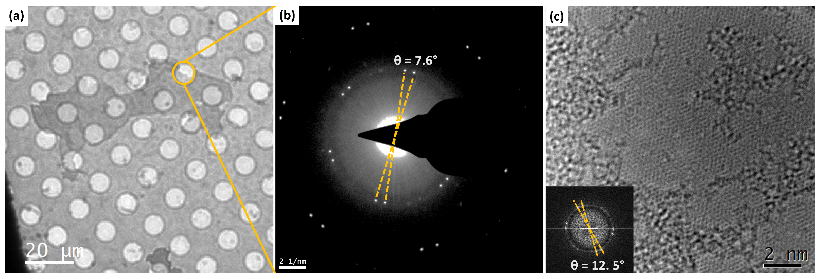
Figure 1a shows a typical SAED pattern and
Figure 1b shows a high-resolution TEM image of two bi-layers with a
rotation angle. The distribution of rotation angles was found to be spread over the whole angular range of
–
. Note that only this range needs to be considered, since the rotation angle
and its complement
yield identical interfaces, except for a trivial
rigid body rotation. The results are summarized in
Table 1 and the histogram shown in
Figure 2. Additionally, we have measured the rotation angles in HRTEM images using the fast Fourier transform (FFT) in various images, as in the example shown in
Figure 1b. In the table, the columns labeled
and
, respectively, contain the angles measured as indicated in
Figure 1 and a rational approximant
obtained from Equation (
1). Since there are an infinite number of approximants for any given experimental accuracy, the ones given in
Table 1 were calculated using continued fractions of increasingly higher orders until the difference
(shown in the third column) between measured angles and those resulting from substituting the calculated approximant in Equation (
1) was smaller than
. When the angular distance between two or more measured angles was smaller than the experimental error (
), they were grouped together; in such cases, the value of
that is given is the group’s average.
Figure 2 also shows the plot of the Shannon entropy [
12] against
of the displacement space, which is the space of all the possible Burgers vectors of interfacial dislocations [
14]. The details of this calculation are given in the next section. For now, note that the entropy plot has sharp troughs at certain discrete values of
, which are best described in terms of the parameterized rotation angle
, defined by
With x; k and n integers, it becomes clear that entropy troughs are located at angles where k is either 1 or 0, as indicated by the value of written below the most prominent troughs.
Note that all measured orientations closely match a sharp trough of the entropy curve where k is either 1 or 0. Even the angles for which , have decimal parts very close to ; we have chosen not to make this approximation, however, in order to preserve the rule of keeping the difference between measured and rationally approximated angles smaller than . The other value with at is a secondary singular value, as explained below.The entropy plot was calculated with a an accuracy of , which is an order of magnitude higher than the experimental error.
These results are also relatively close to the magic angles
reported by Tarnopolsky et. al., where their twisting angles followed a quasi-periodicity at
[
9]. in our case, these matching angles presented sharp troughs in
Figure 2, and also approximated the same periodicity. While most of the matching angles are reported in
Table 1, the angle
is included in the Shannon entropy calculation displayed in
Figure 2. These angles are listed in
Table 2.
The physical explanation of these results can be simply stated in terms of the lattice type formed by the vectors of the displacement field of each interface, as discussed in the following subsections.
3.1. Primary and Secondary Singular States
According to Bollmann [
14], there are special low energy interfaces he called “preferred states” which contain only primary dislocations, i.e., dislocations with Burgers vectors belonging to the crystal (graphene) lattices that compose the interface. Since Bollmann did not have a formal definition of a preferred state, he made the usual vague assumption that they were coincidence orientations with an unspecified small value of
. Bollmann further assumed that under small angular deviations,
form a preferred state, and the interface would try to preserve its low energy configuration by concentrating the strain field in what he called secondary dislocations.In contrast with the primary ones, secondary dislocations have smaller non crystalline Burgers vectors belonging to the DSC lattice, which is the lattice formed by a set of vectors joining the sites of the composing lattices. Bollmann showed that secondary Burgers vectors could be calculated from a different interface formed by the DSC lattice, and a copy of itself rotated by
. We shall refer to this interface, which is central to the results of this work, as the “secondary interface” or “secondary state”. The experimental observation of secondary dislocations [
15], with dislocation spacings in accordance with Bollmann’s hypotheses, confirmed the physical significance of the secondary interface. Preferred states will hereafter be referred to as singular states or singular interfaces to follow the more common usage [
10].
It has been shown [
16] that the rotation angles
resulting from the substitution of an integer
x for the rational parameter
in Equation (
1) give rise to singular interfaces containing only primary dislocations. It is interesting to note that the set of integers actually partitions the angular space into equivalence classes
whose normal mode is the singular interface at
[
17].
In view of the above, any RGB with rotation angle can be thought of as having two components or states: a singular primary state with rotation angle and a secondary state with rotation angle . It now makes sense to inquire under what circumstances the secondary state is, itself, singular.
To do this, we use Equation (
1) to parameterize
and
as
for some of the integer
x and rational
. After some trigonometry, we find that
, and in substituting
for
, we find that
, which shows that secondary states are, themselves, singular (integer
) when
or
, i.e., when
in Equation (
2) or
is an integer. This is the case of
, since (see
Table 1)
is an integer. Therefore, we conclude that the minima in the entropy plot of
Figure 2 correspond to RGBs which are either singular states or non-singular ones with a singular secondary component. In the next section, we describe the structural implications of this result.
3.2. The Displacement Space lattice
The formal framework for calculating the structure of the displacement space has been given elsewhere [
16]. For completeness, we provide a simpler geometrical description here.
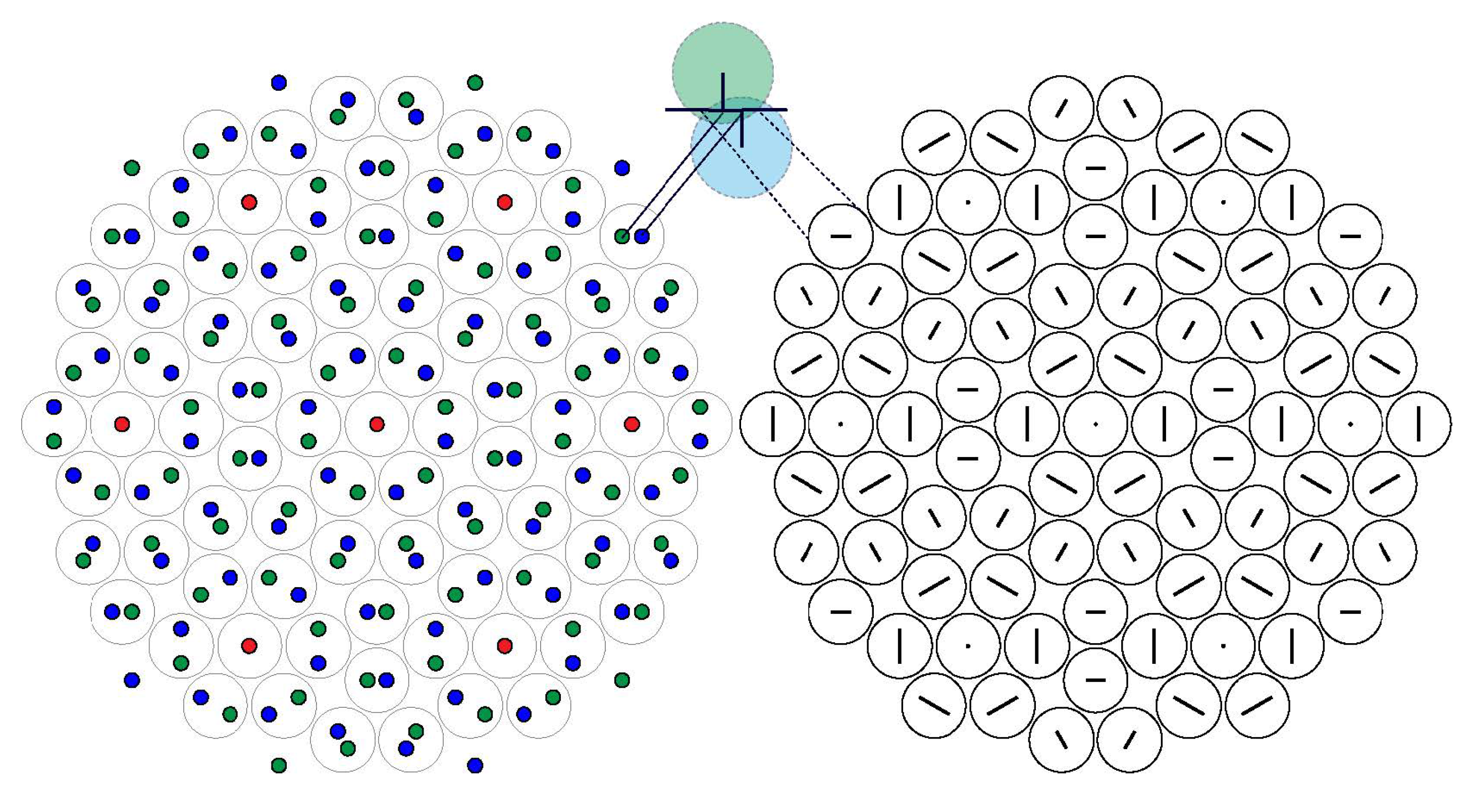
Figure 3 shows, on the left, the dichromatic complex of a graphene bi-layer, and on the right, the set of (encircled) vectors join the displacement vectors, whose size is smaller than half a lattice vector of the graphene lattice. The displacement vectors that fulfill this condition are vectors of the DSC lattice that fall within a window given by the cut-projection formalism [
16] (see
Figure 4), and the circles around each vector are the locus of points of high strain and high electronic density in the interfacial plane between the graphene layers. This pattern not only provides a simpler crystallographic description of the interface by turning the dichromatic complex into a monochromatic one, but, more importantly, it establishes a mapping between the configuration and displacement spaces. Every vector in the displacement space is linked to all the sites of the monochromatic pattern that encircle the dichromatic points separated by that vector.
If
is a rational number, which it always is given the experimental error, then both the set of displacement vectors and its associated monochromatic pattern form a lattice whose degree of complexity depends on
. The complexity of the displacement space lattice (DSL) (multiplied by one inside the window and zero outside) is what the Shannon entropy calculation, shown in
Figure 2, measures.
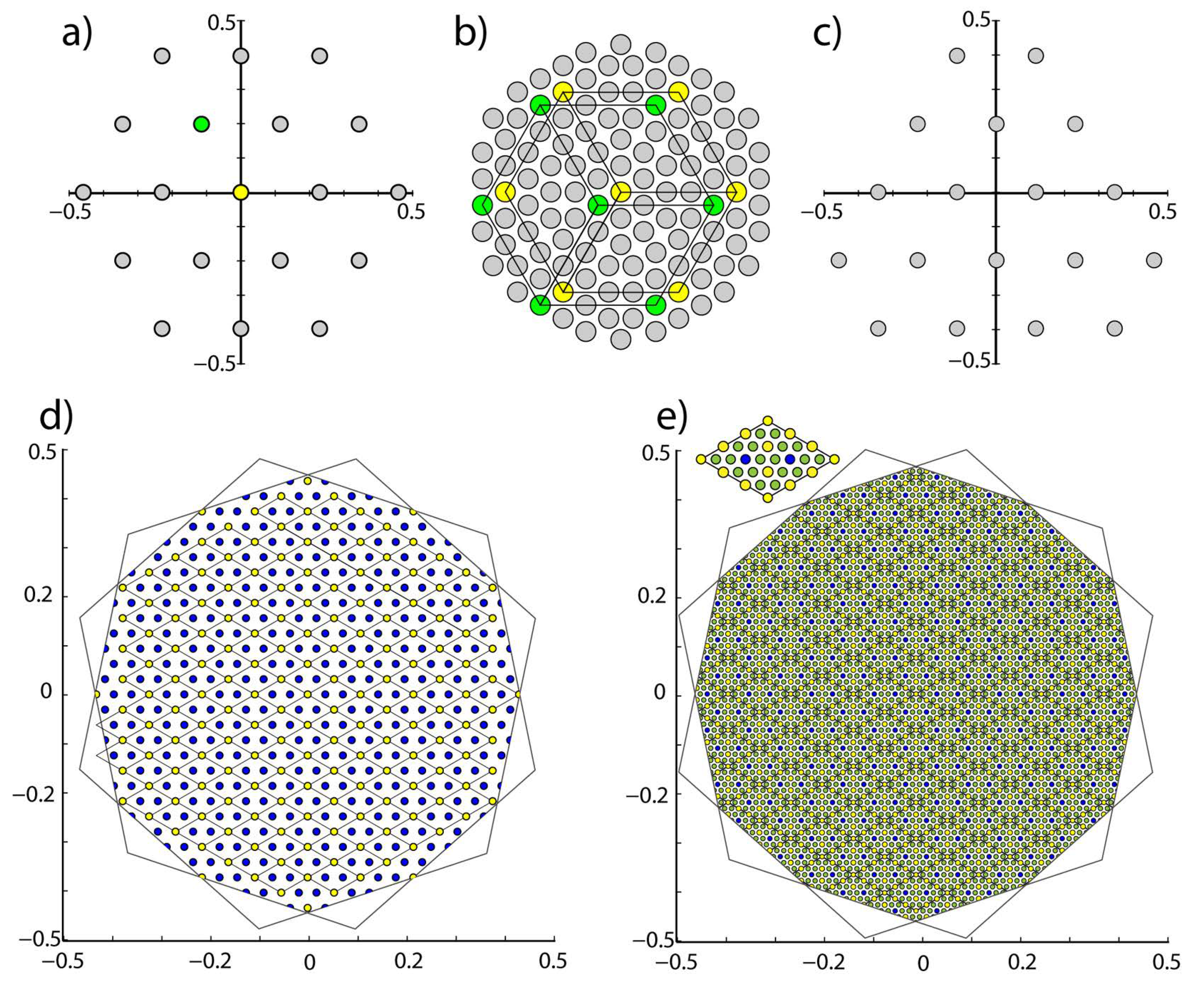
Figure 4 shows examples of DSLs of varying complexities.
The entropy plot in
Figure 2 was calculated by evaluating every
of the Shannon entropy of the distribution of bond lengths in the range [0.0–0.2] in lattice spacing units, divided into 30 intervals. Varying this range and/or the number of intervals may produce slight changes in the relative depths of the troughs, but there is always a sharp local entropy minimum when
is an integer (singular states) or when its decimal part is the inverse of an integer (secondary singular states).
4. Discussion
Given the hexagonal symmetry of the dichromatic pattern, each DSL point is associated with a subset of monochromatic sites that form a primitive hexagonal lattice (see
Figure 4). An example of this is the hexagonal sublattice of coincidence sites associated with the DSL origin.
The DSL is always a simple primitive lattice when its unit cell is built using the basis vectors of the DSC lattice [
18]. However, its degree of complexity is best described in terms of the subset of DSL points associated with hexagonal lattices, whose unit cells have the same areas as the unit cell of the CSL of the singular primary state; the physical significance of this unit cell is that its points represent Burgers vectors of primary dislocations. Using this unit cell, all primary states have a low entropy of the primitive DSL. The higher the order of the continued fraction expansion of
, the higher the contents of the unit cell.
Figure 4 illustrates three levels of complexity of the displacement space. We conclude that crystallographic distinctions between DSLs, and their effects on the number of points that fit inside the window, accounts for the sharp entropy minima of singular and secondary singular interfaces.
In order to conclusively confirm that secondary singular interfaces are preferred states, ab-initio calculations need be performed in the vicinity of secondary singular interfaces at angular intervals close to the value of used in the entropy calculation. This would entail calculations with much larger periodicities than the ones usually performed. We believe that the high computing cost of such calculations, coupled with the lack of a precise definition of singularity, have caused secondary singular interfaces to remain unnoticed.
In the meantime, although the Shannon entropy is not a measure of energy, it can be argued that since the latter depends on the distribution of interatomic distances, it is possible that interfaces with simpler distributions have lower energies. This is, after all, the role that dislocations play in reducing the elastic energy of crystalline materials.
Considering singular secondary interfaces as preferred (local energy minima) orientations not only accounts for the results obtained here for graphene, but it also explains other observations of spontaneously occurring nonsingular interfaces. For example, in the case of 001 twist interfaces in the cubic system, there are no singular orientations in the interval
, (
) to
, (
), both
interfaces. Yet, a number of interfaces in this range were observed by Chaudhari and Matthews [
11]; in particular, those seen in their histogram near
;
and
, which appear to be the secondary singular
and
. Although under the vague small
criterion,
could have been considered a preferred state by Bollmann. The fact is that its DSL is not primitive, evidencing that a small value of
does not imply singularity.
5. Conclusions
Numerous calculations [
10] have shown that singular interfaces have lower energies. This, however, does not answer the question of what happens with RGBs that start out far away from a singular orientation and do not have enough kinetic energy to rotate into a singular state. For example,
Figure 2 shows that there are no singular RGBs between
, and
so that any bi-layer starting to grow in the middle of this
interval would have to rotate more than one degree to find a singular orientation. Our results suggest that bi-layers starting out with a random rotation angle will try to rotate into a nearby secondary singular state. This appears to have been the case with the three
bi-layers observed at
.
The experimental accuracy provided by the present experimental setup is not enough to experimentally confirm that secondary singular states are indeed the preferred low energy states; to do this, an experimental accuracy equal to, or better than, the step used in the entropy calculation would be required. In spite of this, the consistent observation of RGBs near entropy minima, and the fact that secondary singular interfaces have been observed in other systems, supports this hypothesis.
Given the relevance of determining the mechanisms that control the precise orientation in designing materials with tailor-made properties, our results evidence the need to perform ab-initio calculations at, and close to, secondary singular orientations. Moreover, experiments using more accurate techniques to measure rotation angles are also needed to clarify this important point.


