Article

Two-Colour Spectrally Multimode Integrated SU(1,1) Interferometer

by
Alessandro Ferreri
1,2,* and
Polina R. Sharapova
2
1
Institute for Quantum Computing Analytics (PGI-12), Forschungszentrum Jülich, 52425 Jülich, Germany
2
Department of Physics, Paderborn University, Warburger Strasse 100, 33098 Paderborn, Germany
*
Author to whom correspondence should be addressed.
Symmetry 2022, 14(3), 552; https://doi.org/10.3390/sym14030552
Submission received: 11 February 2022 / Revised: 1 March 2022 / Accepted: 3 March 2022 / Published: 9 March 2022
(This article belongs to the Section Physics)

Abstract

:
Multimode integrated interferometers have great potential for both spectral engineering and metrological applications. However, the material dispersion of integrated platforms constitutes an obstacle that limits the performance and precision of such interferometers. At the same time, two-colour nonlinear interferometers present an important tool for metrological applications, when measurements in a certain frequency range are difficult. In this manuscript, we theoretically developed and investigated an integrated multimode two-colour SU(1,1) interferometer operating in a supersensitive mode. By ensuring the proper design of the integrated platform, we suppressed the dispersion, thereby significantly increasing the visibility of the interference pattern. The use of a continuous wave pump laser provided the symmetry between the spectral shapes of the signal and idler photons concerning half the pump frequency, despite different photon colours. We demonstrate that such an interferometer overcomes the classical phase sensitivity limit for wide parametric gain ranges, when up to 3 × 10 4 photons are generated.

1. Introduction

Quantum metrology is the subject devoted to the fabrication and optimisation of high-precision interferometers. The interest in both quantum metrology and interferometry has been growing rapidly, and currently, these subjects can be acknowledged as some of the trend topics in quantum optics of the last few decades [1,2,3,4,5]. Surely, a boost in this direction was brought about by the first detection of gravitational waves, which provided a further valuable tool to our comprehension of the universe [6].
Conveniently, interferometers can be classified into two classes, linear interferometers and nonlinear or SU(1,1) interferometers, according to the presence of passive or active components, respectively [7]. In particular, the linear interferometer is characterised by passive elements, such as beam splitters, which maintain the total number of photons throughout the entire interference process, whereas the nonlinear interferometer includes active elements, typically optical parametric amplifiers (OPAs), triggering the creation of photons. This fundamental difference affects the strategy that has to be employed to achieve optimal phase sensitivity, i.e., the precision to trace the interference pattern [8]. Indeed, on the one hand, in order to beat the classical shot noise limit (SNL), the linear interferometer requires the presence of squeezed or quantum-correlated input states [9], such as the NOON state [10], with a specific photon statistics [11,12]. On the other hand, due to the generation of the squeezed vacuum state by the OPAs, the SU(1,1) interferometer can overcome the SNL without any sort of seed, namely with the quantum vacuum as the input state [13], thereby potentially reaching the Heisenberg limit (HL), which is the limitation imposed by the time–energy uncertainty principle [14].
An excellent candidate for the source of squeezed and entangled photons in various linear and nonlinear interferometric schemes is the parametric down-conversion (PDC) process, which in the last few decades has been successfully realised in various nonlinear materials [15,16,17] and even recently in nanostructures [18,19]. Another fruitful nonlinear process is four-wave mixing (FWM), which can be implemented in waveguides, fibres [20], and even in atomic ensembles [21] to produce narrowband photon pairs with a long coherence time, which can be a great advantage in avoiding additional compensation techniques required for typical PDC-based photon sources. However, the possibility to control the frequency of both signal and idler photons by just applying a specific periodic pole makes waveguide-based PDC sources more versatile with respect to their atomic-based counterparts. Usually, photons emitted via PDC or FWM, typically called signal and idler photons, are generated in broadband spatial and spectral modes, whose role in interferometry has already been proven both theoretically and experimentally [22,23,24,25,26]. As an example, it has been demonstrated that the possibility of controlling the number of spectral modes, and therefore the amount of spectral/temporal correlations between signal and idler photons, can determine the behaviour of the quantum interference pattern in the four-photon Hong–Ou–Mandel scenarios [27].
It is therefore reasonable to believe that any specific realisation of the SU(1,1) interferometer based on realistic nonlinear photon sources should take the multimode structure of the emitted radiation into account. Thus, in [28], it was already demonstrated how a proper state engineering [29] of the photon source allows one to reduce the dispersion within the interferometer and therefore improve both the visibility of the interference pattern and the accuracy in the phase scanning. In addition, proper spectral engineering of PDC sources allows the creation of correlated photons of different colours. During the last decade, the realisation of such non-degenerate PDC sources with specific spectral features has become widespread [30,31,32,33], while their application in interference systems such as Hong–Ou–Mandel [34] and nonlinear Mach–Zehnder interferometers [33] seems to be very promising.
Finally, the interest in integrated devices has recently grown due to both their small footprint and high efficiency [35,36,37]. Such technologies are already utilised in quantum interference scenarios [38,39], in the realisation of non-degenerate PDC sources suitable for single-photon heralding [40], as well as in the generation of polarisation-entangled photons [41].
In this manuscript, we theoretically developed a spectrally multimode non-degenerate integrated SU(1,1) interferometer, whose signal and idler photons are spectrally distinguishable and orthogonally polarised. As an example, we considered potassium titanyl phosphate (KTP) waveguides; however, the concept of such an interferometer can be applied to various integrated platforms. In order to ensure the symmetry between the spectral distributions of signal and idler photons with respect to half the pump frequency, and therefore to cause strong quantum correlations between the photons, we made use of a continuous wave pump laser. We demonstrate that the presented device works in the supersensitive mode beyond the classical SNL. The spectral distinguishability of the generated photons, the miniaturised integrated design, and the compact size of the interferometer, together with the ability to operate in a highly sensitive regime, make this device a powerful tool for future research in the field of quantum optics and metrology.
The paper is organised as follow: In Section 2, we discuss the control of the spectral distinguishability of the generated photons by means of the polling period and present a theoretical model for describing integrated two-colour SU(1,1) interferometers based on non-degenerate PDC sources. In Section 3, we show how dispersion within the two-colour SU(1,1) interferometer can be suppressed by properly designing an integrated platform, and we analyse the phase sensitivity of such a two-colour interferometer and compare the obtained results with the performance of its degenerate counterpart. Finally, we conclude with Section 4 and comment on the quantum features of the presented interferometer.

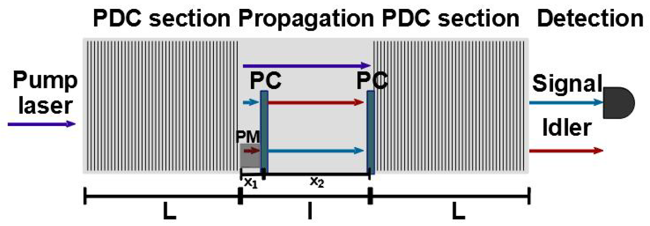
2. Theoretical Model

The integrated interferometer is sketched in Figure 1 and consists of two type-II PDC sources; in particular, two periodically poled potassium titanyl phosphate (ppKTP) waveguides, separated by a non-poled KTP section. The device is pumped by a continuous wave (CW) laser.
The Hamiltonian describing the interferometer is given by [28,42]:
H ^ = i Γ d ω s d ω i F ( ω s , ω i ) a ^ s a ^ i + h . c . ,
where Γ is the coupling constant containing the second-order susceptibility χ ( 2 ) , the pump intensity, and the length of the PDC sections L; ω s and ω i are the frequencies of signal and idler photons, respectively, while a ^ s , i are the creation operators. The function F ( ω s , ω i ) is the joint spectral amplitude (JSA), whose explicit expression is obtained in the next section. The JSA contains both the energy and the momentum conservation of the PDC process, which are expressed by the following relations:
ω p ω s 0 ω i 0 = 0 ,
k o ( ω p ) k o ( ω s 0 ) k e ( ω i 0 ) + 2 π Λ = 0 ,
where ω p , ω s 0 , ω i 0 are the central frequencies of the pump laser and signal and idler photons, respectively, while k x are their wave vectors. The indices o and e correspond to the ordinary and extraordinary polarisation. The constant Λ presents the waveguide polling period, which is required to close the phase matching condition (fulfil the momentum conservation), thereby enabling the pair production. In the following analysis, we neglected the time ordering effect; which is a fair approximation for SU(1,1) interferometers, taking into account the effective narrowing of their spectra due to the nonlinear interference [22].
The lack of degeneracy characterizing two-colour spectra, namely ω s 0 ω i 0 , is achieved by properly setting the polling period Λ of the PDC section. This concretely means that the degree of freedom given by the choice of the periodic pole allows us to determine the central frequencies of the signal and idler photons, and consequently the separation of their spectra. In order to realise the fully spectral distinguishability of signal and idler photons, we firstly estimate the full width at half maximum (FWHM) of their spectra Δ ω in the case of the degenerate PDC source with the polling period Λ d e g [28]; note that the spectra of signal and idler photons are identical in this case due to the use of the CW laser. The variation of the polling period allows signal and idler photons to be generated at different central frequencies with a proper spectral separation. To characterise the splitting of the spectra, we imposed a spectral detuning δ ω , namely a spectral distance between the degenerate frequency ω p / 2 and the central frequency of both the signal and idler photons, ω s 0 = ω p / 2 + δ ω and ω i 0 = ω p / 2 δ ω , such that δ ω Δ ω . This condition ensures the complete spectral splitting of signal and idler photons. The spectral detuning δ ω is identical for both photons in order to fulfil the energy conservation of the process. Eventually, we assumed that the spectral detunings are much smaller than the degenerate frequency ω p / 2 , so that Δ ω δ ω ω p / 2 . Then, the new value of the polling period Λ , which allows the photon pair creation at frequencies ω s 0 and ω i 0 , is calculated by means of the momentum conservation in Equation (3). In contrast to the single-colour SU(1,1) interferometer described in [28], the current device is characterised by two polarisation converters (PCs), which are required for the proper compensation of the group velocities of signal and idler photons.
The presence of two polarisation conversions along the non-poled section enables the preparation of only one periodic pole. Indeed, using a single PC, the lack of degeneracy would push us to utilise a second waveguide with a polling period Λ 2 for the second PDC section, different with respect to the polling period Λ of the first PDC section, in order to compensate the dispersion caused by the different frequencies of the signal and idler photons. The presence of the second PC solves this problem; however, the second PC must be properly arranged with respect to the first one, whose exact position will be calculated in the next section. For the sake of simplicity, we can assume the second PC to be located in front of the second PDC section. The function describing the periodic pole is given by:
g ( z ) = s q u a r e Λ ( z ) 0 < z < L 1 L < z < l + L s q u a r e Λ ( z ( L + l ) ) L + l < z < 2 L + l ,
where the periodic pole of the second PDC is not in phase with the periodic pole of the first one. This fact results in the generation of a global phase in the joint spectral amplitude (JSA).
In a general form, the phase matching function of the whole nonlinear interferometer of length 2 L + l including several poled regions can be given by the expression [43,44,45,46]:
Φ ( ω s , ω i ) = 0 2 L + l d z g ( z ) e i 0 z d ξ Δ k ( ξ ) ,
where Δ k ( ξ ) is the phase matching at the position ( ξ ) . Using Equation (4) and taking into account only the first-order terms in the Fourier decomposition of g ( z ) , the phase matching function describing the whole interferometer presented in Figure 1 with two periodically poled regions given by Equation (4) becomes:
Φ ( ω s , ω i ) = 0 L d z e i 2 π z Λ e i 0 z d ξ Δ k ( ξ ) + L + l 2 L + l d z e i 2 π ( z L l ) Λ e i 0 z d ξ Δ k ( ξ ) ,
where the phase matching Δ k ( ξ ) takes the following expressions in different regions of the interferometer:
Δ k ( ξ ) = Δ k = k o ( ω p ) k o ( ω s ) k e ( ω i ) 0 < z < L Δ k = k o ( ω p ) k o ( ω s ) k e ( ω i ) L < z < L + x 1 Δ k ¯ = k o ( ω p ) k e ( ω s ) k o ( ω i ) L + x 1 < z < L + x 1 + x 2 = L + l Δ k = k o ( ω p ) k o ( ω s ) k e ( ω i ) L + l < z < 2 L + l ,
where k e ( ω i ) = k e ( ω i ) + δ k e ( ω i ) is the modified wavevector of the idler photon in the phase modulation region. Such a change of the wavevector can be performed by applying an external voltage. Hence, introducing an average phase imparted by external voltage φ = δ k e ( ω i 0 ) x 1 with respect to the central frequency of the idler photon ω i 0 , one can define the difference of optical paths in the phase modulation region as Δ k x 1 = Δ k x 1 + δ k e ( ω i ) x 1 = Δ k x 1 + φ δ k e ( ω i ) δ k e ( ω i 0 ) Δ k x 1 + φ , since the relation δ k e ( ω i ) δ k e ( ω i 0 ) 1 holds in the vicinity of ω i 0 .
We now evaluate two integrals in Equation (6). The first integral provides the JSA of the first PDC section:
0 L d z e i 2 π z Λ e i 0 z d ξ Δ k ( ξ ) = 0 L d z e i 2 π z Λ e Δ k z L sinc Δ β L 2 e i Δ β L 2 ,
where Δ β = Δ k + 2 π Λ .
The second integral can be evaluated as follows:
L + l 2 L + l d z e i 2 π ( z L l ) Λ e i 0 z d ξ Δ k ( ξ ) = L + l 2 L + l d z e i 2 π ( z L l ) Λ e i Δ k L e i Δ k x 1 e i Δ k ¯ x 2 e i Δ k ( z x 1 x 2 L ) = L sinc Δ β L 2 e i Δ β L 2 e i 2 π ( L l ) Λ e i ( Δ k Δ k ) x 1 e i ( Δ k ¯ Δ k ) x 2 e i Δ β ( L + l ) .
Using the definition of the averaged phase introduced above and collecting Equations (6), (8) and (9), one can write the expression for the joint spectral amplitude, which under the condition of the undepleted CW pump has the form:
F ( ω s , ω i ) = C δ ( ω p ω s ω i ) sinc Δ β L 2 e i Δ β L 2 1 + e i φ e i Δ k ¯ x 2 e i Δ k ( L + x 1 ) ,
where the δ -function indicates the CW pump, while C is the normalisation constant. We noticed that the length of the PDC source within the sinc-function fashions the width of the joint spectral intensity (JSI) and, therefore, the FWHM of the spectra of both signal and idler photons. The pondered choice of L therefore plays a crucial role in the realisation of the spectral distinguishability of signal and idler photons. Neglecting time-ordering effects and performing the Schmidt decomposition of the joint spectral amplitude F ( ω s , ω i ) = n λ n u n ( ω s ) v n ( ω i ) [47], one can obtain the following expression for the spectral distribution of the signal photons [42]:
N ( ω s ) = n | u n ( ω s ) | 2 sinh 2 [ λ n G ] ,
where parameter G includes both the coupling constant Γ and the normalisation constant of the JSA. The spectral distribution of the idler photons can be obtained by replacing u n ( ω s ) with v n ( ω i ) in Equation (11). The normalised spectral distributions of the photons generated in the SU(1,1) interferometer with PDC sections of length L = 8 mm and the polling period of Λ = 133 μ m are presented in Figure 2.

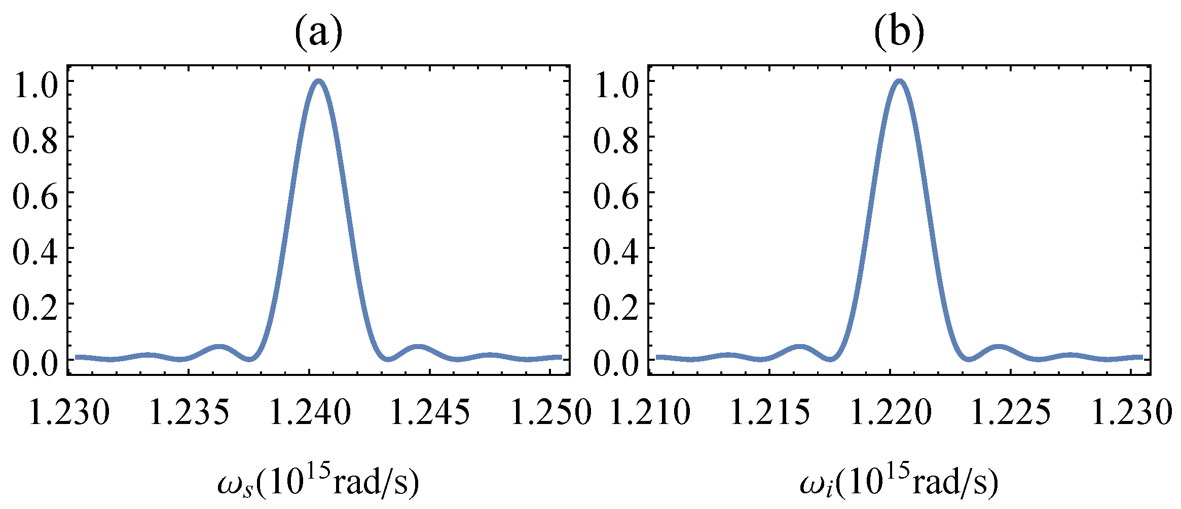
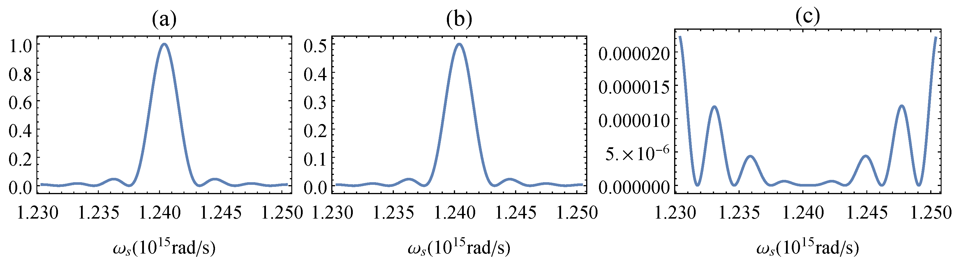
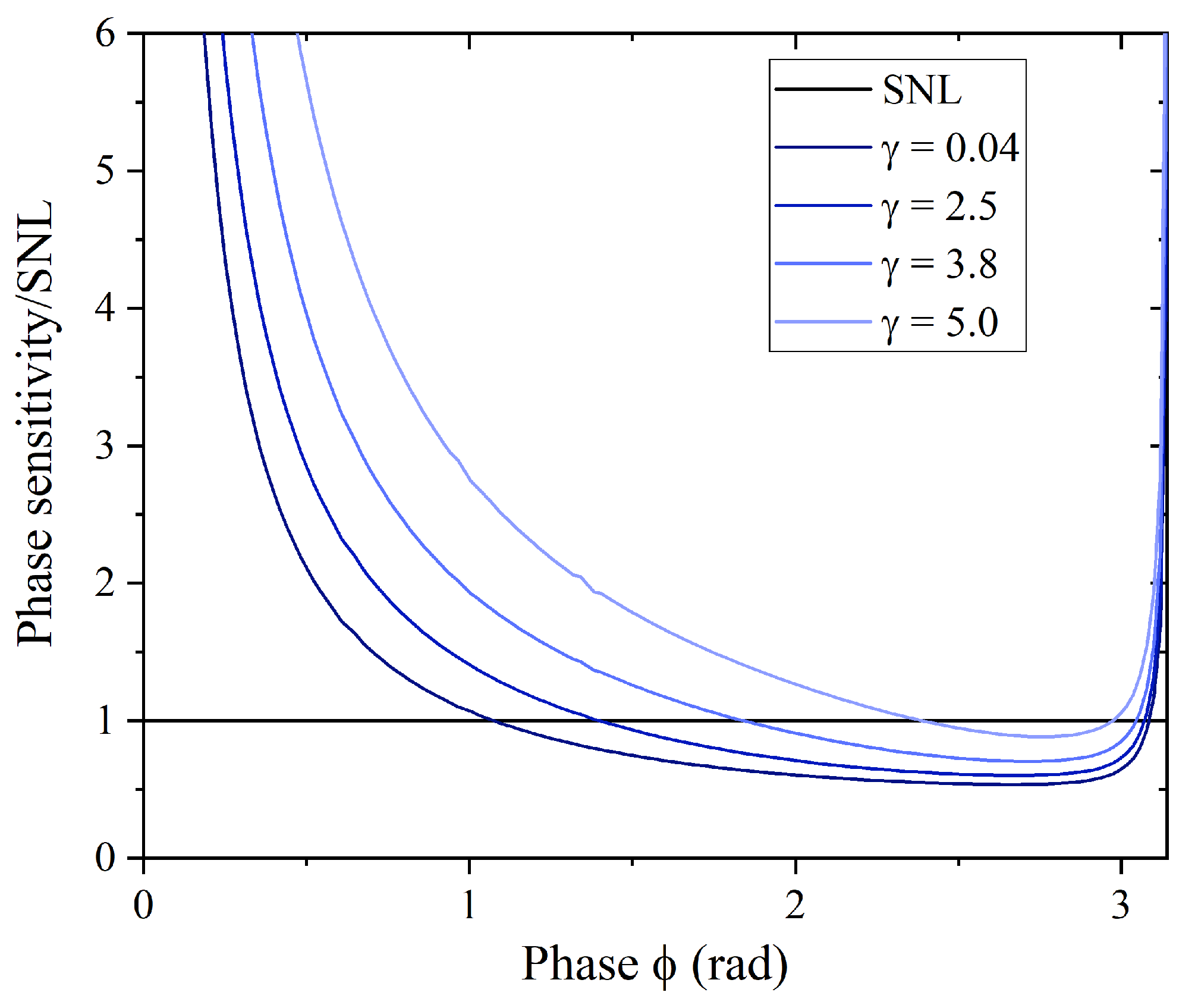
3. Dispersion Suppression and Phase Sensitivity

The regime of destructive interference is very important for reducing noise and improving phase sensitivity in SU(1,1) interferometers [8]. Analysing a degenerate multimode SU(1,1) interferometer, we already found that the shape of the JSI and the number of generated photons at different imparted phase φ are strongly conditioned by the arrangement of various components within the integrated device [28]. In this section, in order to improve the phase sensitivity of the non-degenerate two-colour SU(1,1) interferometer, we elaborate a strategy for reducing the number of generated photons in the destructive interference regime by properly placing polarisation converters.
We start by noticing that according to the last line of Equation (10), the JSA is modulated by a cosine function, whose argument depends on φ . However, the two exponential terms at the end of the second line explicitly depend on the frequencies of both signal and idler photons; this causes the dispersion, which prevents the suppression of photon generation in the destructive interference regime. Nevertheless, the use of the proper positions of polarisation converters x 1 and x 2 allowed us to compensate for the first-order dispersion terms and thereby reduce the arguments of such exponential factors to a mere additional global phase.
To find such positions, we applied the Taylor expansion to the wavevectors of the signal and idler photons around their central frequencies ω s 0 and ω i 0 , respectively. In the zeroth order, we have:
Δ k ( 0 ) ( L + x 1 ) + Δ k ¯ ( 0 ) x 2 = 2 π Λ ( L + x 1 ) + K x 2 Φ ,
where K = k o ( ω p ) k e ( ω s 0 ) k o ( ω i 0 ) . One can observe that the zeroth-order term results in a global phase Φ . In the following consideration, we shifted the value of the phase φ by the global phase Φ , in order to have the maximum of the JSA Equation (10) at the phase ϕ = φ + Φ = 0 .
In the first order, one can write the following system of equations:
Δ k ( 1 ) ( L + x 1 ) + Δ k ¯ ( 1 ) x 2 = 0 ,
x 1 + x 2 = l .
By exploiting the presence of strong frequency correlations between signal and idler photons caused by the use of the CW pump laser, ω i = ω p ω s , Equation (13) becomes:
Ω v o , b + Ω v e , r ( L + x 1 ) + Ω v e , b + Ω v o , r x 2 = 0 ,
where Ω = ω s ω p / 2 δ ω is the frequency detuning and v = ( k / ω ) 1 are the group velocities calculated with respect to the central frequencies of the photons. Here, we determined the central frequencies of photons by the indices r and b, namely r corresponds to the “red” idler photon ω r ω i 0 = ω p / 2 δ ω , while b to the “blue” signal photon ω b ω s 0 = ω p / 2 + δ ω . The indices e and o refer to the extraordinary and ordinary polarisation of photons. The solution of the coupled Equations (14) and (15) allowed us to find the proper positions of both polarisation converters in order to suppress the first-order dispersion terms and obtain quasi-perfect interference at the output of the two-colour SU(1,1) interferometer:
x 1 = v e , r v o , b ( v e , b v o , r ) l + v e , b v o , r ( v o , b v e , r ) L v e , b v e , r v o , b + v e , b v e , r v o , r v e , b v o , b v o , r v e , r v o , b v o , r ,
x 2 = v o , r v e , b ( v e , r v o , b ) ( l + L ) v e , b v e , r v o , b + v e , b v e , r v o , r v e , b v o , b v o , r v e , r v o , b v o , r .
Figure 3 presents the signal spectra normalised to the maximum intensity for three different phases corresponding to the regimes of constructive ϕ = 0 (Figure 3a) and destructive ϕ = π (Figure 3c) interference, as well as to the intermediate regime with the phase ϕ = π / 2 (Figure 3b). As can be observed in Figure 3c, the intensity of the signal photon in the destructive interference case is drastically reduced with respect to the constructive interference regime, although a noise at large frequency detunings | Ω | > 0 is present. The presence of this noise is caused by the fact that our technique for compensating the group velocities of signal and idler photons succeeds in the proximity of the central frequencies (namely, where the main peaks of the intensity spectra are expected), whereas it fails for frequencies far from ω s 0 and ω i 0 , resulting in the emergence of residual photons. The same issue was already observed in the degenerate SU(1,1) interferometer [28]. In both degenerate and two-colour frameworks, the presence of this residual radiation hinders the perfect interference and, therefore, affects the precision of the interferometer, which can be estimated by means of the phase sensitivity [14]:
| Δ ϕ | = Δ N N / ϕ ,
where Δ N is the standard deviation of the number of photons, while N is the mean number of photons.
Figure 4 shows the trend of the phase sensitivity calculated with respect to the signal photons and normalised to the shot noise limit (SNL) when varying the internal phase of the interferometer. The shot noise limit, which determines the classical phase sensitivity bound, is calculated relative to the number of photons inside the interferometer N i n [13]:
| Δ ϕ S N L | = 1 N i n .
Since the phase sensitivity is a symmetrical function with respect to the point ϕ = π , we only report the range [ 0 , π ] . As already experienced in [28], the normalised phase sensitivity diverges in the proximity of both ϕ = 0 and ϕ = π . The presence of these divergences can be mathematically clarified by looking at Equation (18): At ϕ = 0 , both the number of photons and its variance reach the maximum value, whereas the derivative is identically equal to zero; at ϕ = π , the presence of residual photons prevents the variance of the photon number from dropping to zero, whereas the derivative of N is identically equal to zero, being at the point of minimum intensity.
As can be seen from Figure 4, the presented interferometer can perform the phase scan in a supersensitive mode, where the phase sensitivity overcomes the classical limit set by the SNL. One can observe that the normalised phase sensitivity dramatically depends on the parametric gain, which is defined by γ = G ( ϕ = 0 ) λ 1 ( ϕ = 0 ) , where G ( ϕ = 0 ) includes both the coupling constant of the PDC process and the normalisation factor of the JSA, and λ 1 ( ϕ = 0 ) is the first eigenvalue of the spectral Schmidt mode decomposition of JSA [47]. To estimate the gain, both the parameter G ( ϕ ) and the first Schmidt eigenvalue λ 1 ( ϕ ) are evaluated at the maximum of intensity when ϕ = 0 [28]. We stress that by varying the gain opportunely, we can let the number of photons vary from N ( ϕ = 0 ) 0.12 for γ 0.04 to N ( ϕ = 0 ) 10 9 for γ 10.0 .
The dependence of the minimum values of the normalised phase sensitivity on the gain is underlined in Figure 5. It can be seen that the two-colour SU(1,1) interferometer operates in the supersensitive regime for the same gain region as the degenerate (single-colour) SU(1,1) interferometer [28]. Moreover, the phase sensitivity of both interferometers behaves in the same way, and its degradation is observed with an increase in the gain. We attributed the worsening of the performance at higher gains to the high-order dispersion terms, which cause the emergence of the central peak at ϕ = π in Figure 4 and prevent the improvement of the phase sensitivity with increasing gain, in contrast to the single-plane-wave mode scenarios [48,49,50,51], where the worsening of the phase sensitivity is associated only with the presence of internal losses (Since the primary interest of this work was to develop a multimode description of two-colour integrated SU(1,1) interferometers, we decided to avoid the consideration of losses and focused our investigation on the role of dispersion in the phase estimation problem. Accounting for losses, whose influence on the phase sensitivity is already well known in the literature, would require a considerable extension of the existing theory.) [52,53,54,55]. An improvement of the phase sensitivity in the multimode scenario can be performed by using narrowband spectral filters, which select a spectral range around the central frequency of the measured signal photons [28]. Nevertheless, despite deterioration in phase sensitivity at high gains, we noticed that the presence of a supersensitivity range was maintained at gain values of about four, namely when the interferometer produces about 3 × 10 4 photons.
In addition, we would like to point out that a high-quality conversion of polarisation is very important for the interferometer’s performance. Indeed, the unconverted signal and idler photons will not enter the second crystal at the same time and, therefore, will not participate in the interference process. This will lead to residual intensity at the point of destructive interference and deterioration of the phase sensitivity. However, thanks to longitudinal walk-off, such unconverted photons have a time delay different from that of fully converted photons and can be eliminated in the post-selection process. Moreover, when considering broadband light, it is important that all the frequencies that form the photon spectra are correctly converted. Therefore, the conversion window of both polarisation converters must be greater than the bandwidth of the generated photons. In an integrated design, the conversion window depends on the polling period and the length of polarisation converters [38]; therefore, their size and structure must be properly designed for a fruitful experimental realisation. In addition to polarisation converters, for a successful experimental implementation of the reported device, effective integrated non-degenerate PDC sources [40,41] together with integrated detectors [56,57], which have recently been realised in different integrated platforms, are strongly required. Finally, an electro-optic circuit that combines the generation, routing, and manipulation of photons on a compact integrated chip was recently demonstrated in [58], paving the way for the experimental realisation of various linear and nonlinear interferometric circuits on a single chip.

4. Conclusions

In this paper, we modelled a high-performance integrated SU(1,1) interferometer whose output photons are characterised by frequency distinguishability. The spectral separation of signal and idler photons was achieved by the correct choice of the periodic pole of both PDC sources composing the interferometer. At the same time, a compensation of the group velocities of photons was preformed by using two polarisation converters placed at the appropriate positions inside the interferometer, which results in a suppression of dispersion and, consequently, leads to an improvement in the accuracy of the interferometer. We demonstrated that the phase sensitivity of the presented multimode non-degenerate interferometer overcomes the classical limit and reaches the same magnitudes as in the case of a degenerate SU(1,1) interferometer.
Our results showed that the possibility of fully controlling the intensity of the output radiation, the spectral characteristics, and distinguishability of signal and idler photons offers a high degree of manipulation and makes this device a useful photon source for a large variety of optical scenarios. Moreover, the discussed interferometer benefits from its reduced footprint due to the integrated design, as well as from its outstanding performance in the phase scanning. The latter was confirmed by the fact that the phase sensitivity of the interferometer can overcome the shot noise limit, while the interferometer can still generate a considerable amount of photons. This specific feature of the presented interferometer originates from a combination of two factors: the use of a CW laser and the proper location of two polarisation converters, which allowed us to reduce the dispersion, drastically decrease the number of photons in the destructive interference regime, and thereby, maximise the visibility of the interference pattern.
The presented design of the two-colour SU(1,1) interferometer can be realised on various integrated platforms and can be of wide interest for metrological applications where the measurement over one of the photons is challenging. The efficiency of this interferometer can be further tested by making use of different seeding strategies. Furthermore, we leave the realisation of the high-performance two-colour SU(1,1) interferometer, whose emitted photons preserve both frequency and polarisation entanglement, for future work. A more detailed analysis can be accomplished by including the effects of time ordering to describe the PDC state [59,60]. Accounting for these effects can slightly modify the output photon number distribution in the high-gain regime and affect the phase sensitivity. Finally, this model will soon be upgraded by accounting for internal losses, which typically further erode the efficiency of interferometers.

Author Contributions

Conceptualization, A.F. and P.R.S.; methodology, A.F. and P.R.S.; software, A.F.; validation, A.F.; formal analysis, A.F.; investigation, A.F. and P.R.S.; data curation, P.R.S.; writing—original draft preparation, A.F.; writing—review and editing, P.R.S.; visualization, A.F.; supervision, P.R.S.; funding acquisition, P.R.S. All authors have read and agreed to the published version of the manuscript.

Funding

The work was supported by the Deutsche Forschungsgemeinschaft (DFG) via TRR 142/2, Project C02, and TRR 142/3, Project C10, and via Project SH 1228/3-1, as well as the Forschungszentrum Jülich.

Institutional Review Board Statement

Not applicable.

Informed Consent Statement

Not applicable.

Data Availability Statement

The datasets created and analyzed during the current study are available from the corresponding author upon reasonable request.

Acknowledgments

We acknowledge the financial support of the Deutsche Forschungsgemeinschaft (DFG) via TRR 142/2, Project C02, and TRR 142/3, Project C10, and via Project SH 1228/3-1. We also thank the PC 2 (Paderborn Center for Parallel Computing) for providing the computing time.

Conflicts of Interest

The authors declare no conflict of interest.

References

  1. Giovannetti, V.; Lloyd, S.; Maccone, L. Quantum Metrology. Phys. Rev. Lett. 2006, 96, 010401. [Google Scholar] [CrossRef] [PubMed] [Green Version]
  2. Polino, E.; Valeri, M.; Spagnolo, N.; Sciarrino, F. Photonic quantum metrology. AVS Quantum Sci. 2020, 2, 024703. [Google Scholar] [CrossRef]
  3. Tóth, G.; Apellaniz, I. Quantum metrology from a quantum information science perspective. J. Phys. A Math. Theor. 2014, 47, 424006. [Google Scholar] [CrossRef] [Green Version]
  4. Giovannetti, V.; Lloyd, S.; Maccone, L. Advances in quantum metrology. Nat. Photonics 2011, 5, 222–229. [Google Scholar] [CrossRef]
  5. Řehaček, J.; Hradil, Z.; Stoklasa, B.; Paúr, M.; Grover, J.; Krzic, A.; Sánchez-Soto, L.L. Multiparameter quantum metrology of incoherent point sources: Towards realistic superresolution. Phys. Rev. A 2017, 96, 062107. [Google Scholar] [CrossRef] [Green Version]
  6. Abbott, B.P. Observation of Gravitational Waves from a Binary Black Hole Merger. Phys. Rev. Lett. 2016, 116, 061102. [Google Scholar] [CrossRef]
  7. Luo, K.H.; Santandrea, M.; Stefszky, M.; Sperling, J.; Massaro, M.; Ferreri, A.; Sharapova, P.R.; Herrmann, H.; Silberhorn, C. Quantum optical coherence: From linear to nonlinear interferometers. arXiv 2021, arXiv:2104.02641. [Google Scholar]
  8. Chekhova, M.V.; Ou, Z.Y. Nonlinear interferometers in quantum optics. Adv. Opt. Photonics 2016, 8, 104–155. [Google Scholar] [CrossRef]
  9. Giovannetti, V.; Lloyd, S.; Maccone, L. Quantum-Enhanced Measurements: Beating the Standard Quantum Limit. Science 2004, 306, 1330–1336. [Google Scholar] [CrossRef] [Green Version]
  10. Dowling, J.P. Quantum optical metrology—the lowdown on high-N00N states. Contemp. Phys. 2008, 49, 125–143. [Google Scholar] [CrossRef]
  11. Slussarenko, S.; Weston, M.M.; Chrzanowski, H.M.; Shalm, L.K.; Verma, V.B.; Nam, S.W.; Pryde, G.J. Unconditional violation of the shot-noise limit in photonic quantum metrology. Nat. Photonics 2017, 11, 700. [Google Scholar] [CrossRef] [Green Version]
  12. Demkowicz-Dobrzański, R.; Jarzyna, M.; Kołodyński, J. Chapter Four—Quantum Limits in Optical Interferometry. In Progress in Optics; Wolf, E., Ed.; Elsevier: Amsterdam, The Netherlands, 2015; Volume 60, pp. 345–435. [Google Scholar]
  13. Yurke, B.; McCall, S.L.; Klauder, J.R. SU(2) and SU(1,1) interferometers. Phys. Rev. A 1986, 33, 4033–4054. [Google Scholar] [CrossRef] [PubMed]
  14. Ou, Z.Y. Fundamental quantum limit in precision phase measurement. Phys. Rev. A 1997, 55, 2598–2609. [Google Scholar] [CrossRef]
  15. Shih, Y.H.; Sergienko, A.V.; Rubin, M.H.; Kiess, T.E.; Alley, C.O. Two-photon entanglement in type-II parametric down-conversion. Phys. Rev. A 1994, 50, 23–28. [Google Scholar] [CrossRef] [PubMed]
  16. Rubin, M.H.; Klyshko, D.N.; Shih, Y.H.; Sergienko, A.V. Theory of two-photon entanglement in type-II optical parametric down-conversion. Phys. Rev. A 1994, 50, 5122–5133. [Google Scholar] [CrossRef]
  17. Keller, T.E.; Rubin, M.H. Theory of two-photon entanglement for spontaneous parametric down-conversion driven by a narrow pump pulse. Phys. Rev. A 1997, 56, 1534–1541. [Google Scholar] [CrossRef]
  18. Marino, G.; Solntsev, A.S.; Xu, L.; Gili, V.F.; Carletti, L.; Poddubny, A.N.; Rahmani, M.; Smirnova, D.A.; Chen, H.; Lemaître, A.; et al. Spontaneous photon-pair generation from a dielectric nanoantenna. Optica 2019, 6, 1416–1422. [Google Scholar] [CrossRef] [Green Version]
  19. Santiago-Cruz, T.; Fedotova, A.; Sultanov, V.; Weissflog, M.A.; Arslan, D.; Younesi, M.; Pertsch, T.; Staude, I.; Setzpfandt, F.; Chekhova, M. Photon Pairs from Resonant Metasurfaces. Nano Lett. 2021, 21, 4423–4429. [Google Scholar] [CrossRef]
  20. Alibart, O.; Fulconis, J.; Wong, G.K.L.; Murdoch, S.G.; Wadsworth, W.J.; Rarity, J.G. Photon pair generation using four-wave mixing in a microstructured fibre: Theory versus experiment. New J. Phys. 2006, 8, 67. [Google Scholar] [CrossRef]
  21. Zhang, D.; Ahmed, I.; Hao, L.; Cai, Y.; Li, C.; Zhang, Y.; Zhang, Y. Temporally Correlated Narrowband Biphoton Interference Based on Mach-Zehnder Interferometer. Ann. Der Phys. 2019, 531, 1900300. [Google Scholar] [CrossRef]
  22. Lemieux, S.; Manceau, M.; Sharapova, P.R.; Tikhonova, O.V.; Boyd, R.W.; Leuchs, G.; Chekhova, M.V. Engineering the Frequency Spectrum of Bright Squeezed Vacuum via Group Velocity Dispersion in an SU(1,1) Interferometer. Phys. Rev. Lett. 2016, 117, 183601. [Google Scholar] [CrossRef] [Green Version]
  23. Triginer, G.; Vidrighin, M.D.; Quesada, N.; Eckstein, A.; Moore, M.; Kolthammer, W.S.; Sipe, J.E.; Walmsley, I.A. Understanding High-Gain Twin-Beam Sources Using Cascaded Stimulated Emission. Phys. Rev. X 2020, 10, 031063. [Google Scholar] [CrossRef]
  24. Roux, F.S. Stimulated parametric down-conversion for spatiotemporal metrology. Phys. Rev. A 2021, 104, 043514. [Google Scholar] [CrossRef]
  25. Ou, Z.Y.; Li, X. Quantum SU(1,1) interferometers: Basic principles and applications. APL Photonics 2020, 5, 080902. [Google Scholar] [CrossRef]
  26. Frascella, G.; Mikhailov, E.E.; Takanashi, N.; Zakharov, R.V.; Tikhonova, O.V.; Chekhova, M.V. Wide-field SU(1,1) interferometer. Optica 2019, 6, 1233–1236. [Google Scholar] [CrossRef] [Green Version]
  27. Ferreri, A.; Ansari, V.; Silberhorn, C.; Sharapova, P.R. Temporally multimode four-photon Hong–Ou–Mandel interference. Phys. Rev. A 2019, 100, 053829. [Google Scholar] [CrossRef] [Green Version]
  28. Ferreri, A.; Santandrea, M.; Stefszky, M.; Luo, K.H.; Herrmann, H.; Silberhorn, C.; Sharapova, P.R. Spectrally multimode integrated SU(1,1) interferometer. Quantum 2021, 5, 461. [Google Scholar] [CrossRef]
  29. Paterova, A.V.; Krivitsky, L.A. Nonlinear interference in crystal superlattices. Light. Sci. Appl. 2020, 9, 82. [Google Scholar] [CrossRef]
  30. Kitaeva, G.K.; Kornienko, V.V.; Leontyev, A.A.; Shepelev, A.V. Generation of optical signal and terahertz idler photons by spontaneous parametric down-conversion. Phys. Rev. A 2018, 98, 063844. [Google Scholar] [CrossRef]
  31. Dvernik, L.S.; Prudkovskii, P.A. Azimuthal eigenmodes at strongly non-degenerate parametric down-conversion. Appl. Phys. B 2021, 127, 1–10. [Google Scholar] [CrossRef]
  32. Luo, K.H.; Herrmann, H.; Krapick, S.; Brecht, B.; Ricken, R.; Quiring, V.; Suche, H.; Sohler, W.; Silberhorn, C. Direct generation of genuine single-longitudinal-mode narrowband photon pairs. New J. Phys. 2015, 17, 073039. [Google Scholar] [CrossRef]
  33. Kuznetsov, K.A.; Malkova, E.I.; Zakharov, R.V.; Tikhonova, O.V.; Kitaeva, G.K. Nonlinear interference in the strongly nondegenerate regime and Schmidt mode analysis. Phys. Rev. A 2020, 101, 053843. [Google Scholar] [CrossRef]
  34. Riedmatten, H.d.; Marcikic, I.; Tittel, W.; Zbinden, H.; Gisin, N. Quantum interference with photon pairs created in spatially separated sources. Phys. Rev. A 2003, 67, 022301. [Google Scholar] [CrossRef] [Green Version]
  35. Tanzilli, S.; Martin, A.; Kaiser, F.; De Micheli, M.; Alibart, O.; Ostrowsky, D. On the genesis and evolution of Integrated Quantum Optics. Laser Photonics Rev. 2012, 6, 115–143. [Google Scholar] [CrossRef] [Green Version]
  36. Caspani, L.; Xiong, C.; Eggleton, B.J.; Bajoni, D.; Liscidini, M.; Galli, M.; Morandotti, R.; Moss, D.J. Integrated sources of photon quantum states based on nonlinear optics. Light. Sci. Appl. 2017, 6, e17100. [Google Scholar] [CrossRef]
  37. O’Brien, J.; Patton, B.; Sasaki, M.; Vučković, J. Focus on integrated quantum optics. New J. Phys. 2013, 15, 035016. [Google Scholar] [CrossRef] [Green Version]
  38. Sharapova, P.R.; Luo, K.H.; Herrmann, H.; Reichelt, M.; Meier, T.; Silberhorn, C. Toolbox for the design of LiNbO3-based passive and active integrated quantum circuits. New J. Phys. 2017, 19, 123009. [Google Scholar] [CrossRef]
  39. Ono, T.; Sinclair, G.F.; Bonneau, D.; Thompson, M.G.; Matthews, J.C.F.; Rarity, J.G. Observation of nonlinear interference on a silicon photonic chip. Opt. Lett. 2019, 44, 1277–1280. [Google Scholar] [CrossRef]
  40. Krapick, S.; Herrmann, H.; Quiring, V.; Brecht, B.; Suche, H.; Silberhorn, C. An efficient integrated two-color source for heralded single photons. New J. Phys. 2013, 15, 033010. [Google Scholar] [CrossRef] [Green Version]
  41. Herrmann, H.; Yang, X.; Thomas, A.; Poppe, A.; Sohler, W.; Silberhorn, C. Post-selection free, integrated optical source of non-degenerate, polarization entangled photon pairs. Opt. Express 2013, 21, 27981–27991. [Google Scholar] [CrossRef] [Green Version]
  42. Sharapova, P.R.; Tikhonova, O.V.; Lemieux, S.; Boyd, R.W.; Chekhova, M.V. Bright squeezed vacuum in a nonlinear interferometer: Frequency and temporal Schmidt-mode description. Phys. Rev. A 2018, 97, 053827. [Google Scholar] [CrossRef] [Green Version]
  43. Klyshko, D. Ramsey interference in two-photon parametric scattering. J. Exp. Theor. Phys. 1993, 104, 2676–2684. [Google Scholar]
  44. Klyshko, D. Parametric generation of two-photon light in anisotropic layered media. J. Exp. Theor. Phys. 1994, 105, 1574–1582. [Google Scholar]
  45. Santandrea, M.; Stefszky, M.; Ansari, V.; Silberhorn, C. Fabrication limits of waveguides in nonlinear crystals and their impact on quantum optics applications. New J. Phys. 2019, 21, 033038. [Google Scholar] [CrossRef]
  46. Helmfrid, S.; Arvidsson, G.; Webjörn, J. Influence of various imperfections on the conversion efficiency of second-harmonic generation in quasi-phase-matching lithium niobate waveguides. J. Opt. Soc. Am. B 1993, 10, 222–229. [Google Scholar] [CrossRef]
  47. Law, C.K.; Walmsley, I.A.; Eberly, J.H. Continuous Frequency Entanglement: Effective Finite Hilbert Space and Entropy Control. Phys. Rev. Lett. 2000, 84, 5304–5307. [Google Scholar] [CrossRef]
  48. Manceau, M.; Khalili, F.; Chekhova, M. Improving the phase super-sensitivity of squeezing-assisted interferometers by squeeze factor unbalancing. New J. Phys. 2017, 19, 013014. [Google Scholar] [CrossRef]
  49. Anderson, B.E.; Schmittberger, B.L.; Gupta, P.; Jones, K.M.; Lett, P.D. Optimal phase measurements with bright- and vacuum-seeded SU(1,1) interferometers. Phys. Rev. A 2017, 95, 063843. [Google Scholar] [CrossRef] [Green Version]
  50. Li, D.; Yuan, C.H.; Ou, Z.Y.; Zhang, W. The phase sensitivity of an SU(1,1) interferometer with coherent and squeezed-vacuum light. New J. Phys. 2014, 16, 073020. [Google Scholar] [CrossRef]
  51. Plick, W.N.; Dowling, J.P.; Agarwal, G.S. Coherent-light-boosted, sub-shot noise, quantum interferometry. New J. Phys. 2010, 12, 083014. [Google Scholar] [CrossRef]
  52. Li, D.; Yuan, C.H.; Yao, Y.; Jiang, W.; Li, M.; Zhang, W. Effects of loss on the phase sensitivity with parity detection in an SU(1,1) interferometer. J. Opt. Soc. Am. B 2018, 35, 1080–1092. [Google Scholar] [CrossRef] [Green Version]
  53. Marino, A.M.; Corzo Trejo, N.V.; Lett, P.D. Effect of losses on the performance of an SU(1,1) interferometer. Phys. Rev. A 2012, 86, 023844. [Google Scholar] [CrossRef]
  54. Xin, J.; Wang, H.; Jing, J. The effect of losses on the quantum-noise cancellation in the SU(1,1) interferometer. Appl. Phys. Lett. 2016, 109, 051107. [Google Scholar] [CrossRef]
  55. Hu, X.L.; Li, D.; Chen, L.Q.; Zhang, K.; Zhang, W.; Yuan, C.H. Phase estimation for an SU(1,1) interferometer in the presence of phase diffusion and photon losses. Phys. Rev. A 2018, 98, 023803. [Google Scholar] [CrossRef] [Green Version]
  56. Tiedau, J.; Schapeler, T.; Anant, V.; Fedder, H.; Silberhorn, C.; Bartley, T.J. Single-channel electronic readout of a multipixel superconducting nanowire single photon detector. Opt. Express 2020, 28, 5528–5537. [Google Scholar] [CrossRef]
  57. Ferrari, S.; Kahl, O.; Kovalyuk, V.; Goltsman, G.N.; Korneev, A.; Pernice, W.H.P. Waveguide-integrated single- and multi-photon detection at telecom wavelengths using superconducting nanowires. Appl. Phys. Lett. 2015, 106, 151101. [Google Scholar] [CrossRef]
  58. Luo, K.H.; Brauner, S.; Eigner, C.; Sharapova, P.R.; Ricken, R.; Meier, T.; Herrmann, H.; Silberhorn, C. Nonlinear integrated quantum electro-optic circuits. Sci. Adv. 2019, 5, eaat1451. [Google Scholar] [CrossRef] [Green Version]
  59. Quesada, N.; Sipe, J.E. Effects of time ordering in quantum nonlinear optics. Phys. Rev. A 2014, 90, 063840. [Google Scholar] [CrossRef] [Green Version]
  60. Christ, A.; Brecht, B.; Mauerer, W.; Silberhorn, C. Theory of quantum frequency conversion and type-II parametric down-conversion in the high-gain regime. New J. Phys. 2013, 15, 053038. [Google Scholar] [CrossRef] [Green Version]
Figure 1. Schematic model of the two-colour SU(1,1) interferometer. To produce spectrally non-degenerate and orthogonally polarised photons, the pump laser interacts with two PDC sections consisting of periodically poled KTP waveguides of length L. Different polarisations are depicted by the red and blue colours. The PDC sections are separated by the non-poled KTP section of length l. Two polarisation converters, located at the x 1 and x 2 positions, switch the polarisations of signal and idler photons in order to ensure a proper compensation of their group velocities when coming to the second PDC section. An additional phase for the idler photon is provided and controlled by the phase modulator PM. The signal photon is finally detected.
Symmetry 14 00552 g001
Figure 2. Normalised spectra of (a) signal and (b) idler photons. The FWHM of both is Δ ω = 2 × 10 12 rad/s, and the spectral detuning of both is δ ω = 10 × 10 12 rad/s. The following parameters were used for the calculations: L = 8 mm, x 1 1.038 mm, x 2 8.962 mm, Λ = 133 μ m, pump wavelength λ p = 766 nm, ϕ = φ + Φ = 0 ; see the discussion around Equation (12) for more details.
Symmetry 14 00552 g002
Figure 3. Normalised spectra of signal photons at (a) ϕ = 0 , (b) ϕ = π / 2 , and (c) ϕ = π . The normalisation is performed with respect to the maximum intensity in the constructive interference case, when ϕ = 0 . The following parameters were chosen and fixed for all further calculations: λ p = 766 nm, L = 8 mm, x 1 1.038 mm, x 2 8.962 mm, Λ = 133 μ m. The choice of δ ω = 10 13 rad/s ensures the fully spectral distinguishability of signal and idler photons.
Symmetry 14 00552 g003
Figure 4. The phase sensitivity normalised to the SNL versus the phase at different gains. The SNL is shown by the black line.
Symmetry 14 00552 g004
Figure 5. The minimum values of the normalised phase sensitivity presented in Figure 4 versus gain γ in comparison with the degenerate case reported in [28]. The higher the gain is, the faster the phase sensitivity grows. The SNL is plotted by the black line.
Symmetry 14 00552 g005
Publisher’s Note: MDPI stays neutral with regard to jurisdictional claims in published maps and institutional affiliations.

