
The Opto-Mechanical–Thermal Coupling Analysis and Verification of an All-Aluminum Freeform Imaging Telescope

Abstract
:1. Introduction
2. Design of All-Aluminum Freeform Imaging Telescope
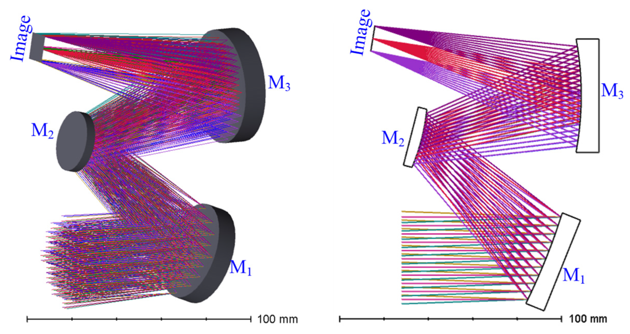
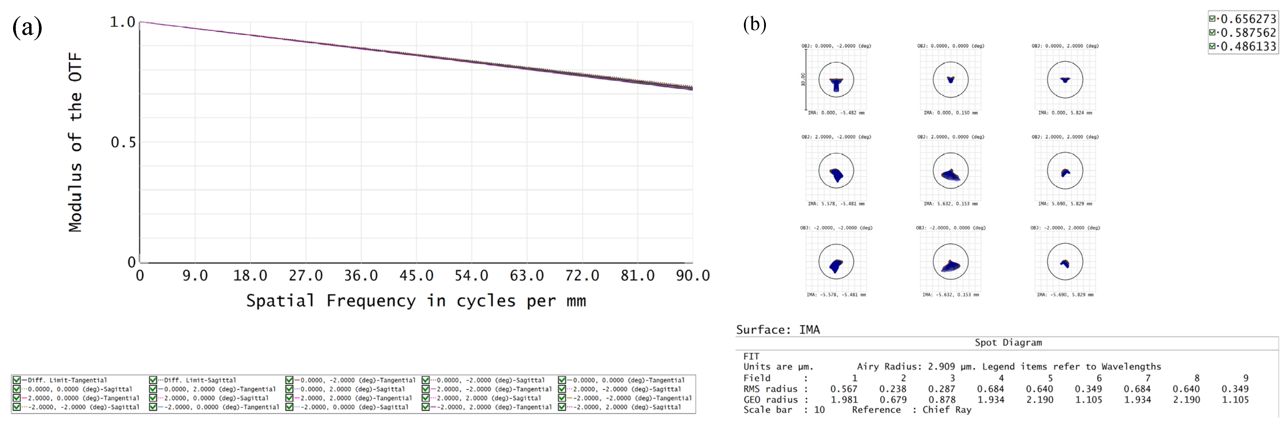
2.1. Optical Design
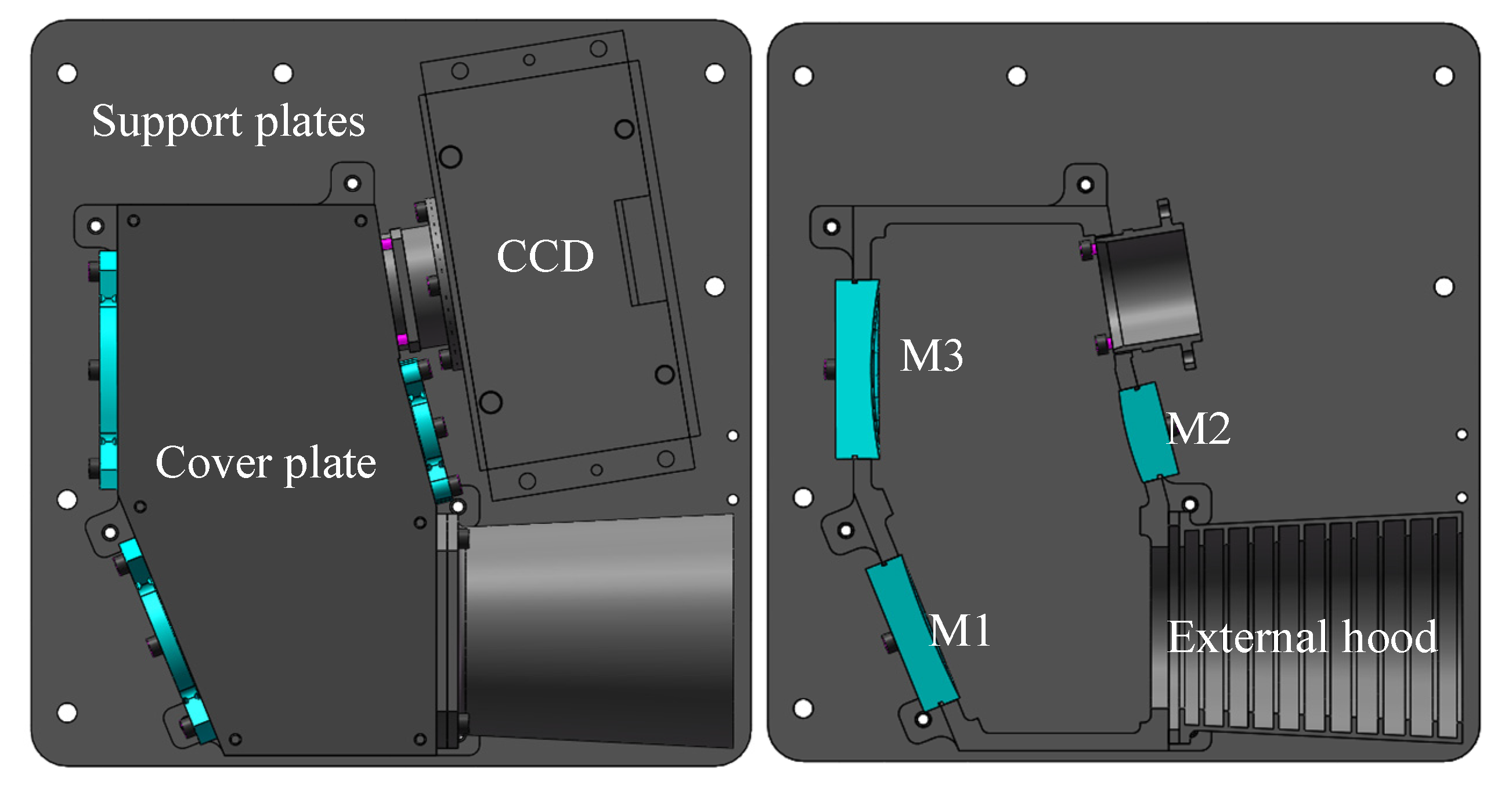
2.2. Structural Design
3. Opto-Mechanical–Thermal Coupling Analysis
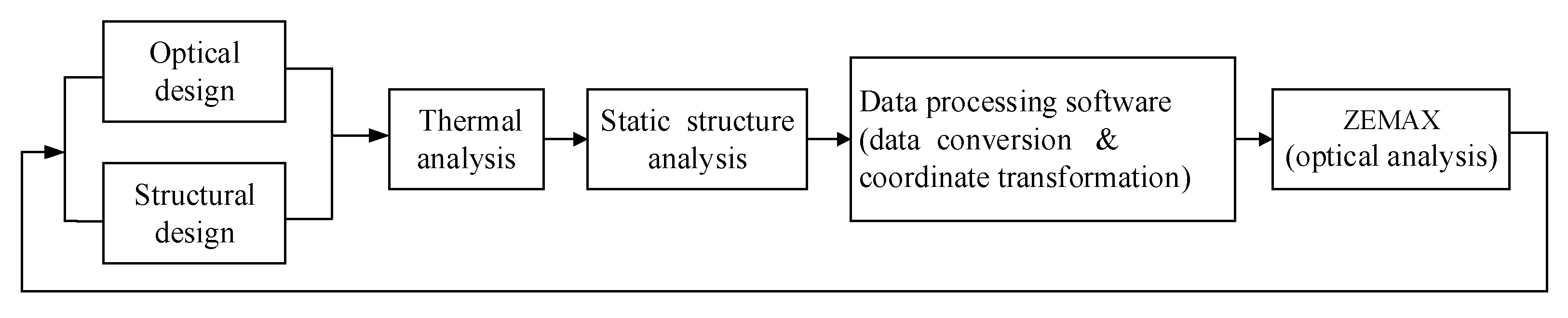
3.1. Principles of Opto-Mechanical–Thermal Coupling Analysis
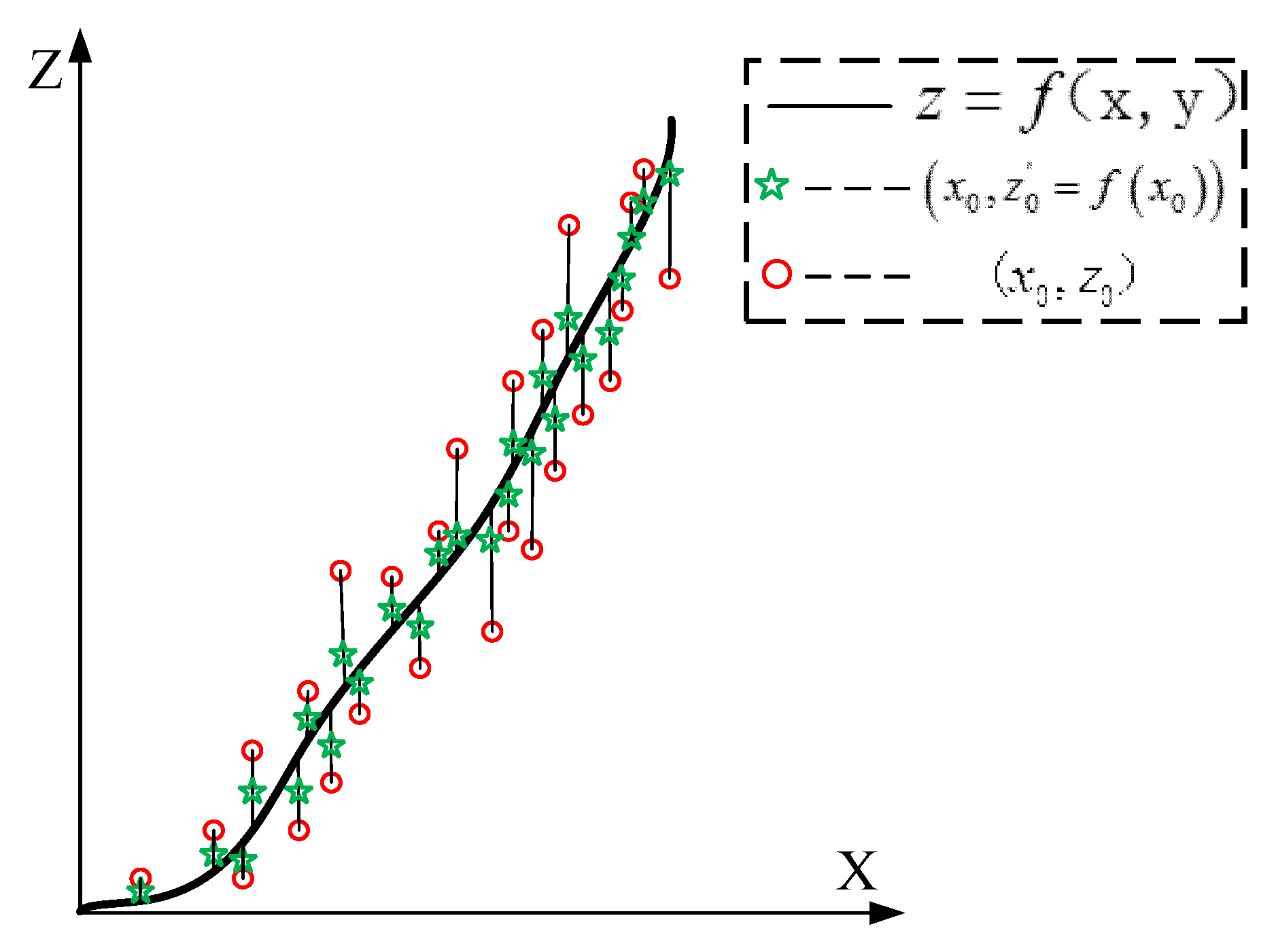
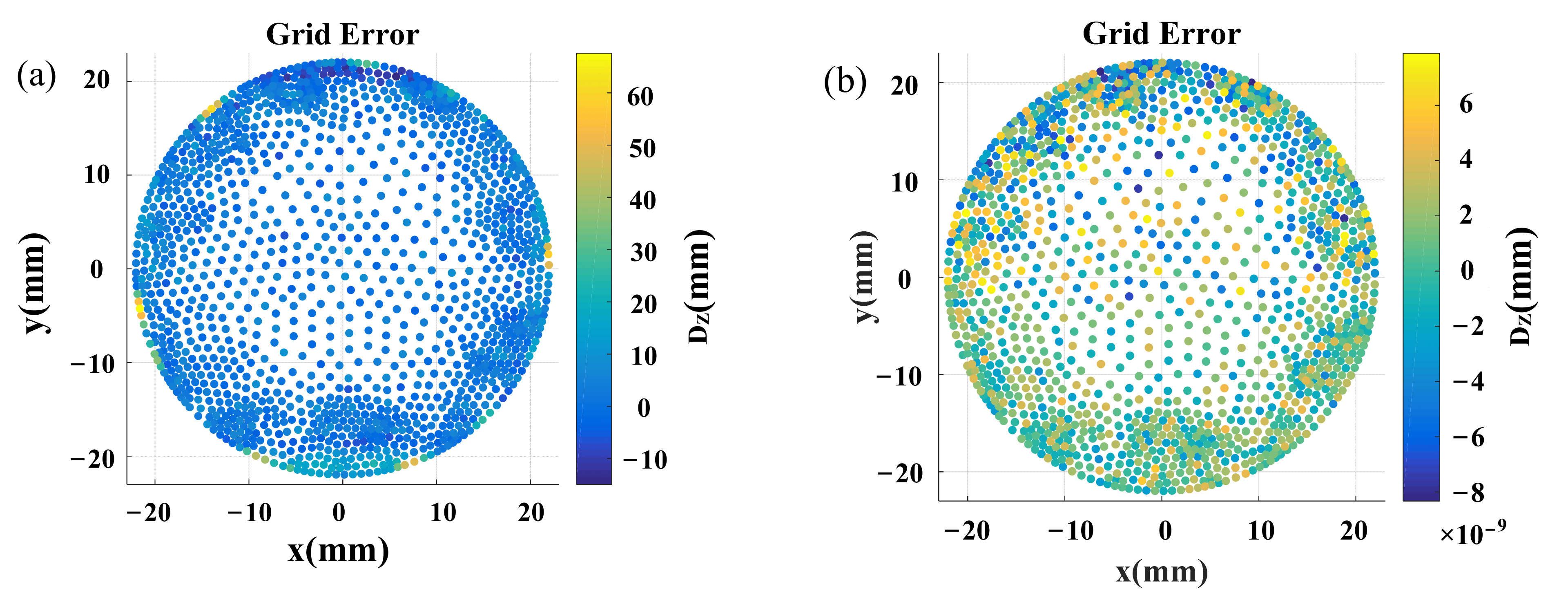
3.2. Data Correction
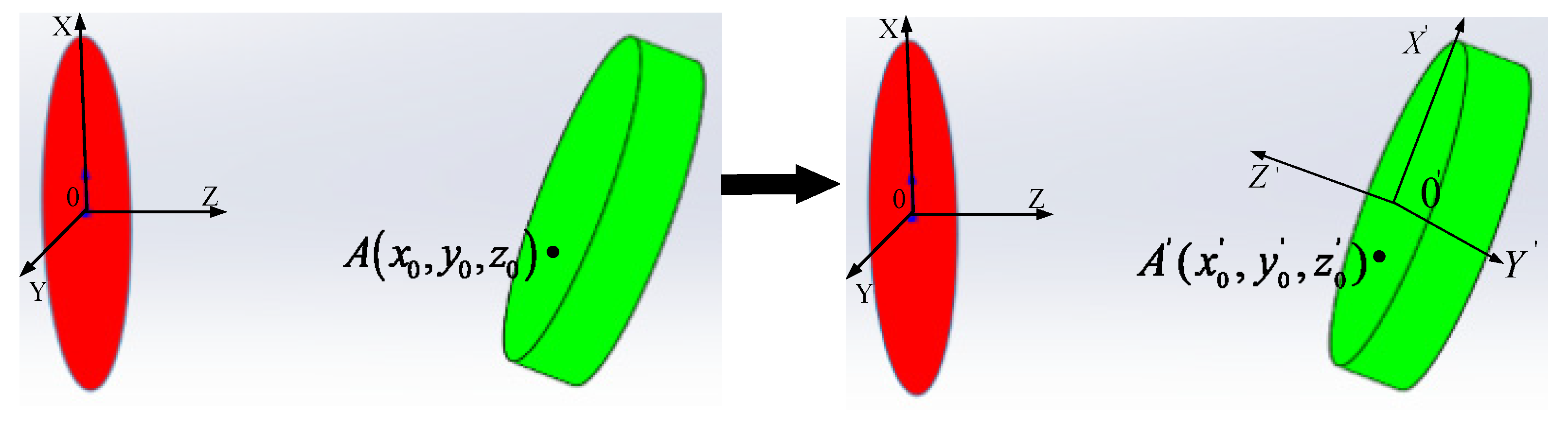
3.3. Coordinate Transformation
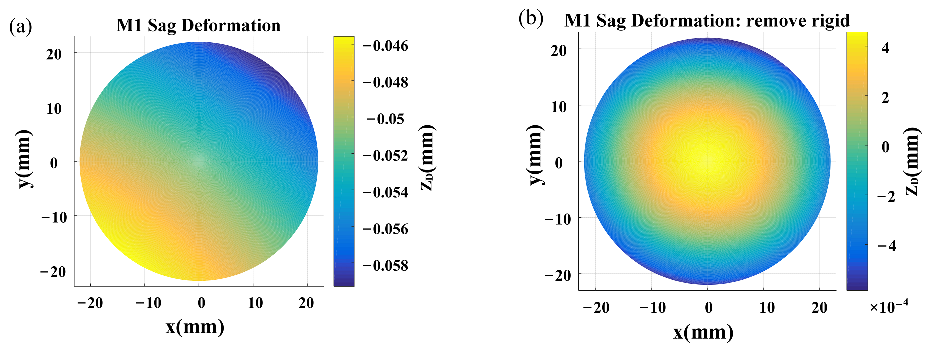
3.4. Opto-Mechanical–Thermal Coupling Analysis
4. Thermal and Optical Testing
5. Conclusions
Author Contributions
Funding
Institutional Review Board Statement
Informed Consent Statement
Data Availability Statement
Acknowledgments
Conflicts of Interest
References
- Bao, Q.H.; Sha, W.; Chen, C.Z.; Ren, J.Y. Lightweight and optimization design of rectangular reflective mirror supported in centre. Infrared Laser Eng. 2017, 46, 718003. [Google Scholar]
- González-Acuña, R.G. Analytical equations for a nonconfocal stigmatic three-freeform-mirror system. Appl. Opt. 2022, 61, 8317–8322. [Google Scholar] [CrossRef] [PubMed]
- RafaGonzález-Acuña, R.G. Set of all possible stigmatic pairs of mirrors. Appl. Opt. 2022, 61, 2513–2517. [Google Scholar] [CrossRef] [PubMed]
- Xie, Y.J.; Mao, X.L.; Li, J.P.; Wang, F.B.; Wang, P.; Gao, R.; Li, X.; Ren, S.J.; Xu, Z.C.; Dong, R.G. The optical design and fabrication of an all-aluminium unobscured two-mirror freeform image telescope. Appl. Opt. 2020, 59, 833–840. [Google Scholar] [CrossRef] [PubMed]
- Yu, B.J.; Dong, Q.Q.; Gu, Y.; Zhao, C.M. Technology of Freeform Surface by Using Slow Tool Servo. Mach. Des. Manuf. 2021, 11, 119–121. [Google Scholar]
- Zhang, J.Z.; Zhang, X.; Tan, S.L. Design and manufacture of an off-axis Aluminium Mirror for Visible-light Imaging. Curr. Opt. Photonics 2017, 1, 364–371. [Google Scholar]
- Zhang, D.G.; Fu, Y.T. Development and Application of Aluminum Mirrors in Optical System. Infrared Technol. 2015, 37, 814–823. [Google Scholar]
- Tan, S.L.; Wang, L.J.; Zhang, X.; Zhang, J.Z.; Xie, X.L. Snap Together Design and Analysis of Visible Quality Aluminum Mirror. J. Chang. Univ. Sci. Technol. (Nat. Sci. Ed.) 2017, 40, 5–8. [Google Scholar]
- Wang, J.P. The Opto-Mechanical Design of Aluminum Optical System and Analysis of Its Thermal Characteristics. Master’s Thesis, National University of Defense Technology, Changsha, China, 2018. [Google Scholar]
- Wang, S. Optical and Mechanical Structure Design and Analysis of All Aluminum Alloy Space Camera. Master’s Thesis, Changchun Institute of Optics, Fine Mechanics and Physics, Changchun, China, 2021. [Google Scholar]
- Beier, M.; Hartung, J.; Peschel, T.; Damm, C.; Gebhardt, A.; Scheiding, S.; Stumpf, D.; Zeitner, U.D.; Risse, S.; Eberhardt, R.; et al. Development, fabrication, and testing of an anamorphic imaging snap-together freeform telescope. Appl. Opt. 2015, 54, 3530–3542. [Google Scholar] [CrossRef]
- Risse, S.; Gebhardt, A.; Damm, C.; Peschel, T.; Stöckl, W.; Feigl, T.; Kirschstein, S.; Eberhardt, R.; Kaiser, N.; Tünnermann, A. Novel TMA telescope based on ultra precise metal mirrors. In Proceedings of the Space Telescopes and Instrumentation 2008: Optical, Infrared, and Millimeter, Marseille, France, 23–28 June 2008; p. 701016. [Google Scholar]
- Zhang, J.C.; Luo, H.Y.; Hu, G.X.; Li, Z.W.; Fang, X.J.; Xiong, W. Thermal/structural/optical integrated analysis on spatial heterodyne Raman spectrometer imaging lens. J. Appl. Opt. 2018, 39, 332–338. [Google Scholar]
- Du, W.F.; Liu, Y.Z.; Gao, W.J.; Hu, X.C. Thermal structure optical integrated analysis of zoom lens for airborne tracking platform. Laser Infrared 2020, 50, 615–622. [Google Scholar]
- Wu, W.; Bai, Y.; Chen, C. Application of optical, mechanical and thermal integration in infrared system. Infrared Laser Eng. 2019, 48, 618002. [Google Scholar] [CrossRef]
- Shi, Y.; Zhang, Y.; Huang, P.; Jia, Y.C.; Li, M.Z. The influence of infrared lens surface change on imaging quality in thermal environment. Opt. Tech. 2018, 44, 365–370. [Google Scholar]
- Yang, T.; Duan, Y.; Cheng, D.W.; Wang, Y.T. Freeform Imaging Optical System Design Theories Development and Applications. Acta Opt. Sin. 2021, 41, 1–29. [Google Scholar]
- Song, X. Integrated Research on Opto-Thermal Analysis and Imaging Analysis. Ph.D. Thesis, Beijing Institute of Technology, BeiJing, China, 2015. [Google Scholar]


| F# | Field of View | Entrance Pupil Diameter (mm) | Wavelength (nm) | Pixel Size (μm2) |
|---|---|---|---|---|
| 4 | 4° × 4° | 40 | 400–700 | 5.5 × 5.5 |
| Density (kg/m3) | Thermal Expansion Coefficient (K−1) | Elastic Modulus (N/m2) | Poisson’s Ratio | Thermal Conductivity (W/(m·K)) |
|---|---|---|---|---|
| 2710 | 2.4 × 10⁻⁵ | 6.9 × 10¹⁰ | 0.33 | 154 |
| Term | M1 | M2 | M3 | Term | M1 | M2 | M3 | Term | M1 | M2 | M3 |
|---|---|---|---|---|---|---|---|---|---|---|---|
| X1Y0 | −3.46 × 10⁻⁵ | −8.14 × 10⁻⁵ | −1.53 × 10⁻³ | X1Y3 | −6.34 × 10⁻¹¹ | 3.15 × 10⁻¹¹ | 9.04 × 10⁻⁶ | X2Y4 | −1.86 × 10⁻¹² | −7.60 × 10⁻¹² | −7.45 × 10⁻⁴ |
| X0Y1 | 1.70 × 10⁻⁴ | 1.46 × 10⁻⁴ | −1.72 × 10⁻³ | X0Y4 | 2.51 × 10⁻⁹ | −1.22 × 10⁻⁷ | −1.02 × 10⁻² | X1Y5 | 1.29 × 10⁻¹³ | 5.60 × 10⁻¹⁴ | −8.28 × 10⁻⁶ |
| X2Y0 | −1.99 × 10⁻⁴ | −7.69 × 10⁻⁴ | −8.37 × 10⁻² | X5Y0 | 1.01 × 10⁻¹¹ | 5.39 × 10⁻¹⁴ | 7.87 × 10⁻⁶ | X0Y6 | −2.29 × 10⁻¹³ | −9.92 × 10⁻¹² | −3.58 × 10⁻⁴ |
| X1Y1 | −3.5 × 10⁻⁸ | 1.84 × 10⁻⁸ | 1.09 × 10⁻⁵ | X4Y1 | 2.70 × 10⁻¹¹ | 1.58 × 10⁻⁹ | 1.00 × 10⁻³ | X7Y0 | 5.62 × 10⁻¹⁵ | 1.23 × 10⁻¹⁶ | 1.87 × 10⁻⁵ |
| X0Y2 | −2.80 × 10⁻⁴ | −2.11 × 10⁻³ | −3.17 × 10⁻¹ | X3Y2 | −2.12 × 10⁻¹¹ | 4.12 × 10⁻¹³ | −4.65 × 10⁻⁵ | X6Y1 | −1.34 × 10⁻¹⁴ | −2.05 × 10⁻¹² | −7.75 × 10⁻⁴ |
| X3Y0 | −4.11 × 10⁻⁹ | −1.44 × 10⁻¹¹ | −3.90 × 10⁻⁵ | X2Y3 | 1.40 × 10⁻¹¹ | 1.83 × 10⁻⁹ | 1.88 × 10⁻⁴ | X5Y2 | −5.11 × 10⁻¹⁵ | −1.15 × 10⁻¹⁶ | −1.07 × 10⁻⁵ |
| X2Y1 | −1.79 × 10⁻⁶ | 2.73 × 10⁻⁷ | 7.67 × 10⁻³ | X1Y4 | −3.12 × 10⁻¹¹ | −2.86 × 10⁻¹³ | −5.29 × 10⁻⁵ | X4Y3 | 1.12 × 10⁻¹⁴ | 2.25 × 10⁻¹² | 7.54 × 10⁻⁴ |
| X1Y2 | 1.26 × 10⁻⁸ | −2.30 × 10⁻⁹ | 4.06 × 10⁻⁵ | X0Y5 | 3.95 × 10⁻¹² | 5.58 × 10⁻¹⁰ | −2.41 × 10⁻⁴ | X3Y4 | −2.48 × 10⁻¹⁴ | −2.00 × 10⁻¹⁵ | −7.52 × 10⁻⁵ |
| X0Y3 | −2.21 × 10⁻⁶ | −8.57 × 10⁻⁶ | −2.20 × 10⁻² | X6Y0 | −3.29 × 10⁻¹³ | 3.54 × 10⁻¹³ | −1.34 × 10⁻⁴ | X2Y5 | 1.79 × 10⁻¹⁴ | 2.29 × 10⁻¹² | 3.42 × 10⁻⁴ |
| X4Y0 | 8.39 × 10⁻⁹ | 4.85 × 10⁻⁸ | −2.67 × 10⁻³ | X5Y1 | −1.92 × 10⁻¹⁴ | −1.12 × 10⁻¹³ | 6.05 × 10⁻⁶ | X1Y6 | −1.64 × 10⁻¹⁴ | 9.19 × 10⁻¹⁶ | −4.55 × 10⁻⁵ |
| X3Y1 | −3.23 × 10⁻¹² | 5.80 × 10⁻¹¹ | −6.95 × 10⁻⁶ | X4Y2 | 5.80 × 10⁻¹³ | 9.22 × 10⁻¹² | −3.64 × 10⁻⁴ | X0Y7 | 2.78 × 10⁻¹⁵ | −3.78 × 10⁻¹³ | −1.27 × 10⁻⁴ |
| X2Y2 | 1.03 × 10⁻⁸ | −3.73 × 10⁻⁸ | −1.07 × 10⁻² | X3Y3 | 1.90 × 10⁻¹³ | 9.70 × 10⁻¹⁴ | −1.13 × 10⁻⁵ |
| Temperature | −55°C | 0°C |
| MTF | 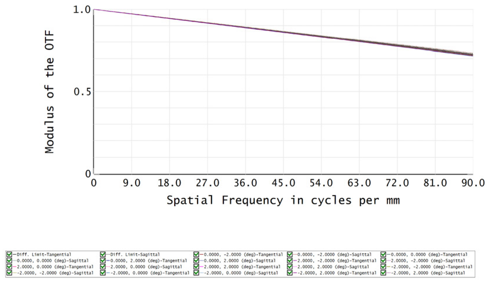 | 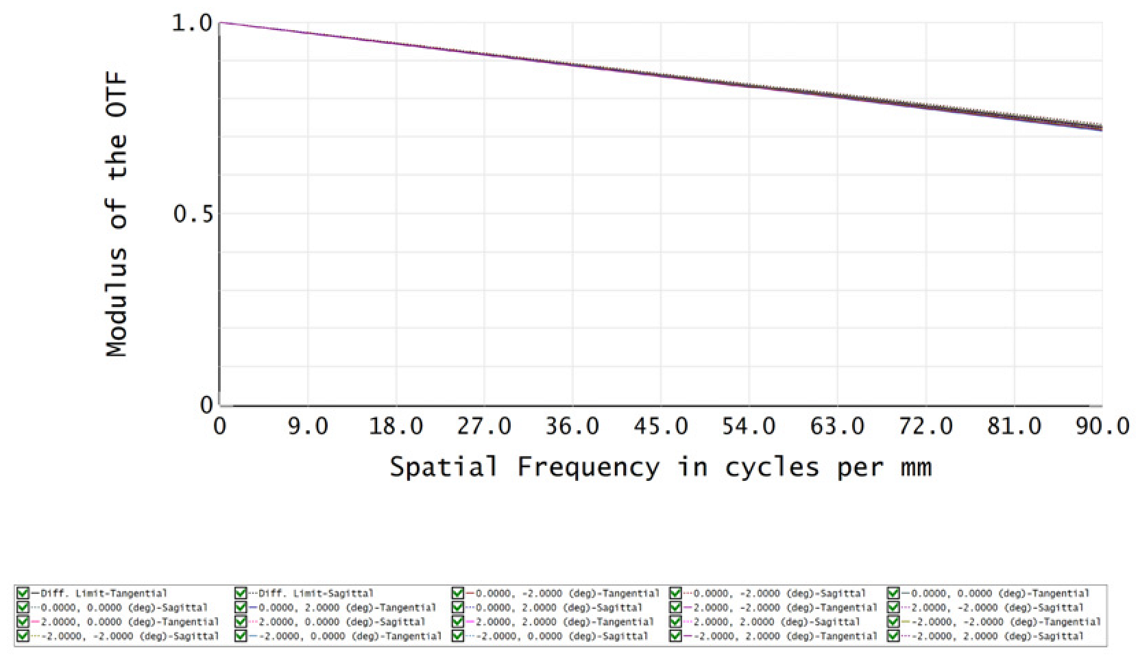 |
| Temperature | 20°C | 70°C |
| MTF | 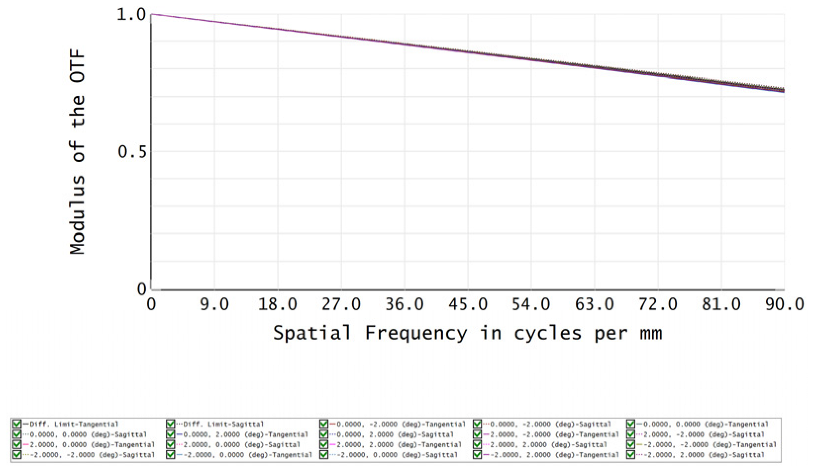 |  |
Publisher’s Note: MDPI stays neutral with regard to jurisdictional claims in published maps and institutional affiliations. |
© 2022 by the authors. Licensee MDPI, Basel, Switzerland. This article is an open access article distributed under the terms and conditions of the Creative Commons Attribution (CC BY) license (https://creativecommons.org/licenses/by/4.0/).
Share and Cite
Gao, R.; Li, J.; Wang, P.; Yu, J.; Xie, Y.; Mao, X. The Opto-Mechanical–Thermal Coupling Analysis and Verification of an All-Aluminum Freeform Imaging Telescope. Symmetry 2022, 14, 2391. https://doi.org/10.3390/sym14112391
Gao R, Li J, Wang P, Yu J, Xie Y, Mao X. The Opto-Mechanical–Thermal Coupling Analysis and Verification of an All-Aluminum Freeform Imaging Telescope. Symmetry. 2022; 14(11):2391. https://doi.org/10.3390/sym14112391
Chicago/Turabian StyleGao, Rong, Jinpeng Li, Peng Wang, Jiadong Yu, Yongjun Xie, and Xianglong Mao. 2022. "The Opto-Mechanical–Thermal Coupling Analysis and Verification of an All-Aluminum Freeform Imaging Telescope" Symmetry 14, no. 11: 2391. https://doi.org/10.3390/sym14112391
APA StyleGao, R., Li, J., Wang, P., Yu, J., Xie, Y., & Mao, X. (2022). The Opto-Mechanical–Thermal Coupling Analysis and Verification of an All-Aluminum Freeform Imaging Telescope. Symmetry, 14(11), 2391. https://doi.org/10.3390/sym14112391